WO2022091806A1 - ホワイトボードフィルム、ホワイトボードおよび覗き見防止システム - Google Patents
ホワイトボードフィルム、ホワイトボードおよび覗き見防止システム Download PDFInfo
- Publication number
- WO2022091806A1 WO2022091806A1 PCT/JP2021/038133 JP2021038133W WO2022091806A1 WO 2022091806 A1 WO2022091806 A1 WO 2022091806A1 JP 2021038133 W JP2021038133 W JP 2021038133W WO 2022091806 A1 WO2022091806 A1 WO 2022091806A1
- Authority
- WO
- WIPO (PCT)
- Prior art keywords
- layer
- whiteboard
- refractive index
- film
- polarizing layer
- Prior art date
- Legal status (The legal status is an assumption and is not a legal conclusion. Google has not performed a legal analysis and makes no representation as to the accuracy of the status listed.)
- Ceased
Links
Images




Classifications
-
- G—PHYSICS
- G03—PHOTOGRAPHY; CINEMATOGRAPHY; ANALOGOUS TECHNIQUES USING WAVES OTHER THAN OPTICAL WAVES; ELECTROGRAPHY; HOLOGRAPHY
- G03B—APPARATUS OR ARRANGEMENTS FOR TAKING PHOTOGRAPHS OR FOR PROJECTING OR VIEWING THEM; APPARATUS OR ARRANGEMENTS EMPLOYING ANALOGOUS TECHNIQUES USING WAVES OTHER THAN OPTICAL WAVES; ACCESSORIES THEREFOR
- G03B21/00—Projectors or projection-type viewers; Accessories therefor
- G03B21/54—Accessories
- G03B21/56—Projection screens
- G03B21/60—Projection screens characterised by the nature of the surface
- G03B21/604—Polarised screens
-
- B—PERFORMING OPERATIONS; TRANSPORTING
- B43—WRITING OR DRAWING IMPLEMENTS; BUREAU ACCESSORIES
- B43L—ARTICLES FOR WRITING OR DRAWING UPON; WRITING OR DRAWING AIDS; ACCESSORIES FOR WRITING OR DRAWING
- B43L1/00—Repeatedly-usable boards or tablets for writing or drawing
-
- G—PHYSICS
- G02—OPTICS
- G02B—OPTICAL ELEMENTS, SYSTEMS OR APPARATUS
- G02B5/00—Optical elements other than lenses
- G02B5/30—Polarising elements
- G02B5/3025—Polarisers, i.e. arrangements capable of producing a definite output polarisation state from an unpolarised input state
- G02B5/3033—Polarisers, i.e. arrangements capable of producing a definite output polarisation state from an unpolarised input state in the form of a thin sheet or foil, e.g. Polaroid
-
- G—PHYSICS
- G02—OPTICS
- G02B—OPTICAL ELEMENTS, SYSTEMS OR APPARATUS
- G02B5/00—Optical elements other than lenses
- G02B5/30—Polarising elements
- G02B5/3025—Polarisers, i.e. arrangements capable of producing a definite output polarisation state from an unpolarised input state
- G02B5/3033—Polarisers, i.e. arrangements capable of producing a definite output polarisation state from an unpolarised input state in the form of a thin sheet or foil, e.g. Polaroid
- G02B5/3041—Polarisers, i.e. arrangements capable of producing a definite output polarisation state from an unpolarised input state in the form of a thin sheet or foil, e.g. Polaroid comprising multiple thin layers, e.g. multilayer stacks
-
- G—PHYSICS
- G02—OPTICS
- G02B—OPTICAL ELEMENTS, SYSTEMS OR APPARATUS
- G02B5/00—Optical elements other than lenses
- G02B5/30—Polarising elements
- G02B5/3083—Birefringent or phase retarding elements
-
- G—PHYSICS
- G03—PHOTOGRAPHY; CINEMATOGRAPHY; ANALOGOUS TECHNIQUES USING WAVES OTHER THAN OPTICAL WAVES; ELECTROGRAPHY; HOLOGRAPHY
- G03B—APPARATUS OR ARRANGEMENTS FOR TAKING PHOTOGRAPHS OR FOR PROJECTING OR VIEWING THEM; APPARATUS OR ARRANGEMENTS EMPLOYING ANALOGOUS TECHNIQUES USING WAVES OTHER THAN OPTICAL WAVES; ACCESSORIES THEREFOR
- G03B21/00—Projectors or projection-type viewers; Accessories therefor
- G03B21/54—Accessories
- G03B21/56—Projection screens
- G03B21/60—Projection screens characterised by the nature of the surface
-
- G—PHYSICS
- G02—OPTICS
- G02B—OPTICAL ELEMENTS, SYSTEMS OR APPARATUS
- G02B5/00—Optical elements other than lenses
- G02B5/02—Diffusing elements; Afocal elements
- G02B5/0273—Diffusing elements; Afocal elements characterized by the use
- G02B5/0284—Diffusing elements; Afocal elements characterized by the use used in reflection
Definitions
- the present invention relates to a whiteboard film, a whiteboard and a peep prevention system.
- the wall (or partition) of the conference room is made of a glass plate (or acrylic plate) and made transparent to obtain a feeling of openness.
- Meeting rooms are often equipped with whiteboards and projector screens, for example, for presentations. While making the walls of the conference room transparent gives a feeling of openness, it can be problematic for an outside third party to snoop on the information displayed on the whiteboard or projector screen in the conference room.
- Whiteboard films used as whiteboards and projector screens are also known.
- Patent Document 1 discloses a peep prevention system having a space, an information screen arranged in the space, and a window portion that separates the space from the surroundings.
- the "information screen” displays information by reflecting and / or emitting polarized light parallel to the first direction, and provides the displayed information in space.
- an information screen an information screen having a whiteboard and a polarizing element attached to the surface of the whiteboard is described.
- the window portion has a transparent substrate and a polarizing element that absorbs polarized light parallel to the first direction. From the outside of the space, the transparent window makes it possible to see the inside of the space while obscuring the information displayed on the information screen.
- the information displayed on the information screen described in Patent Document 1 is from the inside of the space. Visibility when observing may not be sufficient.
- the information screen described in Patent Document 1 is used as a whiteboard, that is, when characters, symbols, pictures, etc. are drawn on the surface of the information screen described in Patent Document 1 with ink containing a pigment or dye. , The visibility of drawn characters, symbols, pictures, etc. when observed from the inside of the space may not be sufficient.
- the problem that the information displayed on the information screen described in Patent Document 1 may not have sufficient visibility may also occur when the information screen described in Patent Document 1 is used as a projector screen.
- the visibility when the projected image is observed from the inside of the space is not sufficient (for example, the contrast ratio of the projected image is not sufficient).
- the contrast ratio of the projected image is not sufficient.
- the present invention has been made to solve the above problems, and whiteboard films and whiteboards having improved visibility of displayed information and peeping prevention having such whiteboard films or whiteboards.
- the purpose is to provide a system.
- the "whiteboard film (or whiteboard) that improves the visibility of the displayed information” is (1) drawn with ink containing a pigment or dye on the surface of the whiteboard film (or whiteboard). At least the effect of improving the visibility of characters, symbols, pictures, etc., or (2) the effect of improving the visibility of the image projected on the whiteboard film (or whiteboard) using a projector.
- a diffuse reflection layer that diffuses and reflects visible light An absorption type polarizing layer having a first transmission axis parallel to the first direction, A whiteboard film having a reflective polarizing layer arranged between the diffuse reflecting layer and the absorbing polarizing layer and having a second transmission axis substantially parallel to the first direction.
- a whiteboard film according to item 1 further comprising a low refractive index layer arranged between the diffuse reflective layer and the reflective polarizing layer and having a refractive index smaller than the refractive index of the diffuse reflective layer.
- the low refractive index layer has a refractive index of 1.30 or less.
- a low refractive index layer arranged between the diffuse reflector and the reflective polarizing layer and having a refractive index smaller than that of the diffuse reflector.
- the low refractive index layer has a refractive index of 1.30 or less.
- the low refractive index layer is an air layer.
- the low refractive index layer is a porous layer.
- the translucent portion is a peep prevention system having a transparent substrate and a polarizing layer having a third transmission axis orthogonal to the first direction.
- a whiteboard film and a whiteboard that can improve the visibility of displayed information, and a peep prevention system having such a whiteboard film or whiteboard.
- FIG. 3 is a schematic cross-sectional view of the whiteboard film 100 according to the embodiment of the present invention. It is a schematic sectional drawing of the whiteboard 100a by embodiment of this invention. It is a figure which shows typically the peep prevention system 1000 which has a whiteboard film 100.
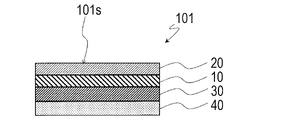
- FIG. 3 is a schematic cross-sectional view of the whiteboard film 101 according to another embodiment of the present invention. It is sectional drawing which shows typically an example of the locus of a light ray at the interface between a diffuse reflection layer 40 and a low refractive index layer 30. It is a schematic sectional drawing which shows an example of the structure of a reflective polarizing layer 10. It is a schematic cross-sectional view of the whiteboard film 900 of the comparative example.
- the whiteboard film, the whiteboard, and the peep prevention system according to the embodiment of the present invention will be described.
- the embodiments of the present invention are not limited to those exemplified below.
- the whiteboard film according to the embodiment of the present invention can form a whiteboard by being attached to a substrate.
- the method of attaching the whiteboard film to the base material is not particularly limited, and for example, it may be adhered using an adhesive or may be attached using a magnet.
- the "adhesive” includes an adhesive (also referred to as a "pressure sensitive adhesive”).
- the whiteboard film may be fixed to the substrate or may be detachably attached.
- the whiteboard film according to the embodiment of the present invention has a diffuse reflection layer that diffusely reflects visible light, an absorption type polarizing layer having a transmission axis (first transmission axis) parallel to the first direction, a diffuse reflection layer and an absorption type. It has a reflective polarizing layer which is arranged between the polarizing layer and has a transmission axis (second transmission axis) substantially parallel to the first direction.
- the reflective polarizing layer transmits the polarized light parallel to the transmission axis and reflects the polarized light orthogonal to the transmission axis.
- the transmission axis of the absorption type polarizing layer and the transmission axis of the reflection type polarizing layer are substantially parallel to each other when the angle formed by the transmission axis of the absorption type polarizing layer and the transmission axis of the reflection type polarizing layer is ⁇ with respect to 0 °. It is permissible to include an error within 5 °.
- the diffuse reflectance of the diffuse reflection layer is, for example, preferably 80% or more, and more preferably 90% or more. Of the total light reflected light when visible light is incident on the diffuse reflection layer, the specular reflection component is preferably, for example, 50% or less (that is, the diffuse reflection component is 50% or more).
- the whiteboard according to the embodiment of the present invention is different from the whiteboard film according to the embodiment of the present invention in that it has a diffuse reflection plate that diffusely reflects visible light instead of the diffuse reflection layer.
- the "diffuse-reflecting plate” refers to a plate that does not require a supporting base material
- the "diffuse-reflecting layer” refers to a material that is generally used while being supported by the base material or a material that cannot exist without the supporting base material. ..
- the diffuse reflection layer and the base material that supports the diffuse reflection layer are sometimes collectively referred to as a diffuse reflection plate.
- the diffuse reflection layer and the base material may integrally form a diffuse reflection plate (without a clear boundary between the diffuse reflection layer and the base material).
- the above description does not exclude the form in which the diffuse reflector is supported by the base material.
- the whiteboard according to the embodiment of the present invention can be used without being supported by the base material.
- the description of the whiteboard film according to the embodiment of the present invention in the present specification also applies to the whiteboard according to the embodiment of the present invention.
- the peep prevention system is a partition that separates the whiteboard film or the whiteboard and the space where the information displayed on the whiteboard film or the whiteboard is provided from the surroundings, and is a partition in the space. It has a partition with a translucent portion that can be seen.
- the translucent portion has a transparent substrate and a polarizing layer having a transmission axis (third transmission axis) orthogonal to the first direction.
- FIG. 1A shows a schematic cross-sectional view of the whiteboard film 100 according to the embodiment of the present invention.
- the whiteboard film 100 has a diffuse reflection layer 40 that diffusely reflects visible light, an absorption type polarizing layer 20, and a reflection type polarizing layer 10 arranged between the diffusion reflection layer 40 and the absorption type polarizing layer 20. ..
- the first transmission axis of the absorption type polarizing layer 20 and the second transmission axis of the reflection type polarizing layer 10 are arranged substantially in parallel.
- the whiteboard film 100 has a reflective polarizing layer 10 between the diffuse reflecting layer 40 and the absorbing polarizing layer 20, so that the efficiency of light utilization is improved.
- the whiteboard film 100 improves the visibility of the displayed information.
- FIG. 1B shows a schematic cross-sectional view of the whiteboard 100a according to the embodiment of the present invention.
- the white board 100a has a diffuse reflection plate 40a for diffusely reflecting visible light, an absorption type polarizing layer 20, and a reflection type polarizing layer 10 arranged between the diffusion reflection plate 40a and the absorption type polarizing layer 20.
- the first transmission axis of the absorption type polarizing layer 20 and the second transmission axis of the reflection type polarizing layer 10 are arranged substantially in parallel.
- the whiteboard film 100 will be mainly described, but the same effect as that of the whiteboard film 100 can be obtained in the whiteboard 100a. That is, the whiteboard 100a has the reflective polarizing layer 10 between the diffuse reflecting plate 40a and the absorbing polarizing layer 20, so that the efficiency of light utilization is improved.
- the whiteboard 100a improves the visibility of the displayed information.
- the whiteboard film 100 is configured so that characters, symbols, figures, etc. can be drawn on the surface 100s, for example, using an ink containing a pigment or a dye (typically a pigment). At this time, the whiteboard film 100 can be used as a whiteboard on which characters and the like can be erased on the surface 100s.
- a protective layer for example, glass
- an antifouling layer made of a fluorine-containing resin or a silicone-containing resin may be further provided on the surface 20a of the absorption-type polarizing layer 20.
- the surface 100s of the whiteboard film 100 may be flat enough to allow characters and the like to be erased.
- the surface 100s of the whiteboard film 100 is the surface 20a of the absorbent polarizing layer 20 in the drawing, and is the surface of the protective layer or the antifouling layer when it has the above-mentioned protective layer or antifouling layer.
- Information displayed on the whiteboard film 100 that is, information such as characters, symbols, and figures drawn with ink on the surface 100s of the whiteboard film 100 is provided to the observer as follows.
- the polarization parallel to the first transmission axis of the absorption type polarizing layer 20 and the second transmission axis of the reflection type polarizing layer 10 is the absorption type polarizing layer 20.
- the reflective polarizing layer 10 is transmitted through the reflective polarizing layer 10 and diffusely reflected on the surface and / or inside of the diffuse reflection layer 40.
- the polarized light parallel to the first transmission axis of the absorption type polarizing layer 20 and the second transmission axis of the reflection type polarizing layer 10 is the reflection type polarizing layer 10 and the absorption type polarizing layer. 20 is passed through in order to reach the observer.
- the whiteboard film 100 exhibits white color, and when characters or the like are drawn with ink on the surface 100s, light of a specific wavelength is absorbed by the ink (pigment). Thereby, information such as characters, symbols, and figures drawn on the surface 100s of the whiteboard film 100 is provided to the observer.
- the polarized light orthogonal to the second transmission axis of the reflection type polarizing layer 10 is reflected by the reflection type polarizing layer 10, and is again incident on the diffuse reflection layer 40 and diffusely reflected. , The degree of polarization is reduced (the polarization is eliminated).
- the polarized light parallel to the first transmission axis of the absorption type polarizing layer 20 and the second transmission axis of the reflection type polarizing layer 10 is the reflection type polarizing layer 10 and the absorption type polarizing layer.
- the polarized light that has passed through 20 and is orthogonal to the second transmission axis of the reflective polarizing layer 10 is reflected by the reflective polarizing layer 10 and is incident on the diffused reflective layer 40 again to be diffusely reflected.
- the efficiency of light utilization is improved. Since the whiteboard film 100 can improve the white brightness, the visibility of the displayed information can be improved.
- the whiteboard film 100 Since the whiteboard film 100 has the absorption type polarizing layer 20 on the front surface, it also has an advantage that the influence of external light reflection can be reduced.
- the whiteboard film 100 can also be used as a projector screen.
- the information displayed on the whiteboard film 100 that is, the image projected on the whiteboard film 100 is provided to the observer as follows.
- the polarized light parallel to the first transmission axis of the absorption type polarizing layer 20 and the second transmission axis of the reflection type polarizing layer 10 is transmitted through the absorption type polarizing layer 20 and the reflection type polarizing layer 10. It is diffusely reflected by the diffuse reflection layer 40.
- the polarized light parallel to the first transmission axis of the absorption type polarizing layer 20 and the second transmission axis of the reflection type polarizing layer 10 is the reflection type polarizing layer 10 and the absorption type polarizing layer.
- the image projected on the whiteboard film 100 is provided to the observer.
- the polarized light parallel to the first transmission axis of the absorption type polarizing layer 20 and the second transmission axis of the reflection type polarizing layer 10 is the reflection type polarizing layer 10 and the absorption type polarizing layer.
- the polarized light that has passed through 20 and is orthogonal to the second transmission axis of the reflective polarizing layer 10 is reflected by the reflective polarizing layer 10 and is incident on the diffused reflective layer 40 again to be diffusely reflected.
- the efficiency of light utilization is improved. Even when the whiteboard film 100 is used as a projector screen, the utilization efficiency of the light emitted from the projector is improved by having the reflective polarizing layer 10.
- the whiteboard film 100 can improve the visibility of the displayed information.
- the utilization efficiency of the light emitted from the projector is improved, so that it is not necessary to use a high-brightness projector in order to ensure the visibility of the displayed information. Further, since the regular reflection (specular reflection) on the surface of the diffuse reflection layer 40 is suppressed, there is an advantage that the local brightening (hot spot) of a part of the projector screen due to the regular reflection is suppressed. ..
- the whiteboard film 100 When the whiteboard film 100 is used as a projector screen, it may further have an antireflection layer provided on the surface 20a of the absorption type polarizing layer 20. By having the antireflection layer on the outermost surface, the specular reflection on the surface 100s of the whiteboard film 100 is suppressed, and the generation of hot spots is further suppressed.
- Japanese Patent No. 2958585 and Japanese Patent Application Laid-Open No. 8-142581 have a projector screen having a structure in which a diffusion layer, an absorption type polarizing layer, and a specular reflection layer (aluminum layer) are arranged in this order from the observer side. It has been disclosed.
- the whiteboard film 100 has an advantage that it is not necessary to provide a diffuser layer on the observer side because the whiteboard film 100 has a diffuser reflector layer 40 instead of the specular reflective layer.
- the polarized light transmitted through the diffusion layer is depolarized. Therefore, as in the peep prevention system described with reference to FIG.
- the information displayed on the whiteboard film 100 is transferred to a person outside the space where the whiteboard film 100 is installed by using the polarization. From the viewpoint of hiding from the viewpoint, it is preferable that the whiteboard film 100 does not have a diffusion layer on the observer side of the absorption type polarizing layer 20 (the side opposite to the reflection type polarizing layer 10 of the absorption type polarizing layer 20).
- the whiteboard film 100 may further have an adhesive layer independently between the diffuse reflection layer 40 and the reflective polarizing layer 10 and between the reflective polarizing layer 10 and the absorption type polarizing layer 20.
- FIG. 2 is a top view schematically showing the peep prevention system 1000 having the whiteboard film 100.
- the peep prevention system 1000 is a partition 300 that separates the whiteboard film 100 and the space 500 in which the information displayed on the whiteboard film 100 is provided from the surroundings, and looks inside the space 500. It has a partition 300 having a translucent portion 200 capable of being capable.
- the translucent unit 200 has a transparent substrate 220 and a polarizing layer 240 having a third transmission axis orthogonal to the first direction.
- the "information displayed on the whiteboard film 100" is, for example, characters, symbols, figures, etc. drawn with ink on the surface 100s of the whiteboard film 100, or is projected onto the whiteboard film 100 using a projector.
- the whiteboard film 100 is attached to the base material 110 in this example.
- the base material 110 supports, for example, the whiteboard film 100 in a state where the surface 100s of the whiteboard film 100 is substantially parallel to the vertical direction.
- the peep prevention system 1000 further includes a projector provided in the space 500 and emitting light toward the surface 100s of the whiteboard film 100.
- the information displayed on the whiteboard film 100 is polarized (that is, the first direction) parallel to the transmission axis of the light transmitted through the absorption type polarizing layer 20 among the light diffusely reflected by the diffuse reflection layer 40. (Polarization parallel to) reaches the observer Pi in the space 500 and is provided to the observer Pi in the space 500. Since the polarized light parallel to the first direction cannot pass through the polarizing layer 240 having the third transmission axis orthogonal to the first direction, the person Po outside the space 500 sees the information displayed on the whiteboard film 100. I can't.
- the degree of polarization of the reflective polarizing layer 10 is lower than the degree of polarization of the absorbing polarizing layer 20, so that the whiteboard film 100 can be formed by having not only the reflective polarizing layer 10 but also the absorbing polarizing layer 20.
- the displayed information can be more reliably hidden (blinded) from the person Po outside the space 500.
- the angle formed by the transmission axis of the absorption type polarizing layer 20 and the transmission axis of the polarizing layer 420 is not 90 °, if the error with respect to 90 ° is within ⁇ 10 °, it is outside the space 500.
- the human Po sees the whiteboard film 100 through the polarizing layer 420 of the translucent portion 200, the information displayed on the whiteboard film 100 can be substantially invisible.
- FIG. 6 shows a schematic cross-sectional view of the whiteboard film 900 of the comparative example.
- the whiteboard film 900 of the comparative example has a diffuse reflection layer 940 that diffuses and reflects visible light, and an absorption type polarizing layer 920.
- the whiteboard film 900 of the comparative example is different from the whiteboard film 100 according to the embodiment of the present invention in that it does not have a reflective absorbing layer.
- Information displayed on the whiteboard film 900 of the comparative example for example, characters, symbols, figures, etc. drawn with ink on the surface 900s of the whiteboard film 900 are provided to the observer as follows.
- the polarized light parallel to the transmission axis of the absorption type polarizing layer 920 passes through the absorption type polarizing layer 920, and the surface of the diffusion reflection layer 940 and / or It is diffusely reflected inside.
- the polarization transmitted through the absorption type polarizing layer 920 is ink such as characters drawn on the surface 900s.
- Light of a specific wavelength is absorbed by (pigment) and reaches the observer.
- information such as characters, symbols, and figures drawn on the surface 900s is provided to the observer.
- the polarized light orthogonal to the transmission axis of the absorption type polarizing layer 920 is absorbed by the absorption type polarizing layer 920 and does not reach the observer.
- the whiteboard film 900 of the comparative example has low light utilization efficiency.
- FIG. 3 shows a schematic cross-sectional view of the whiteboard film 101 according to another embodiment of the present invention.
- the whiteboard film 101 differs from the whiteboard film 100 in that it further has a low refractive index layer 30 arranged between the diffuse reflection layer 40 and the reflective polarizing layer 10.
- the points different from the whiteboard film 100 will be mainly described.
- the refractive index of the low refractive index layer 30 is smaller than the refractive index of the diffuse reflection layer 40.
- the low refractive index layer 30 is transparent to visible light and is made of a translucent material.
- the refractive index of the low refractive index layer 30 is preferably 1.30 or less, for example.
- the low refractive index layer 30 may be an air layer. Alternatively, the low refractive index layer 30 may be a porous layer described later.
- the low refractive index layer 30 may be formed of an adhesive (for example, an adhesive having a refractive index of 1.4 or more and 1.6 or less).
- the whiteboard film 101 has a low refractive index layer 30 to improve the utilization efficiency of the light diffusely reflected inside the diffuse reflection layer 40, and therefore, as compared with the whiteboard film 100. The efficiency of light utilization is further improved.
- the refractive index of the low refractive index layer 30 is smaller than the refractive index of the diffuse reflection layer 40, among the light diffusely reflected inside the diffuse reflection layer 40, the light is incident on the low refractive index layer 30 at an angle equal to or higher than the critical angle. The light is totally reflected (internal total reflection) at the interface between the diffuse reflection layer 40 and the low refractive index layer 30. A part of the light whose incident angle ⁇ i is smaller than the critical angle enters the low refractive index layer 30. Of the light that has entered the low refractive index layer 30, light having a large emission angle ⁇ o from the diffuse reflection layer 40 to the low refractive index layer 30, as shown in FIG. 4, leaks from the end of the low refractive index layer 30.
- the critical angle is small, the ratio of total reflected light is large, so that the above-mentioned light loss can be suppressed. From the viewpoint of improving the efficiency of light utilization, it is preferable that the critical angle is small, and therefore it is preferable that the ratio nl / nr of the refractive index nl of the low refractive index layer 30 to the refractive index nr of the diffuse reflection layer 40 is small.
- the low refractive index layer 30 is directly formed on the surface of the reflective polarizing layer 10, that is, the low refractive index layer 30 is in direct contact with the reflective polarizing layer 10.
- the whiteboard film according to the embodiment of the present invention is not limited to this example, and a further layer (for example, acrylic resin, PET film) transparent to visible light is formed between the low refractive index layer 30 and the reflective polarizing layer 10. ) May have.
- the whiteboard film 101 Similar to the whiteboard film 100, the whiteboard film 101 has a reflective polarizing layer 10 between the diffuse reflecting layer 40 and the absorbing polarizing layer 20, so that the efficiency of light utilization is improved.
- the whiteboard film 101 improves the visibility of the displayed information.
- the whiteboard film 101 instead of the whiteboard film 100 of the peep prevention system 1000, the information displayed on the whiteboard film 101 can be made invisible from the outside of the space 500.
- the absorption-type polarizing layer (hereinafter, may be simply referred to as a polarizing element) is typically a resin film in which a dichroic substance (for example, iodine) is adsorbed and oriented.
- the absorption type polarizing layer may be a single-layer resin film or a laminate of two or more layers of resin films.
- the absorbent polarizing layer composed of a single-layer resin film include highly hydrophilic films such as polyvinyl alcohol (PVA) -based films, partially formalized PVA-based films, and ethylene / vinyl acetate copolymerization-based partially saponified films.
- PVA polyvinyl alcohol
- molecular films include those that have been dyed and stretched with bicolor substances such as iodine and bicolor dyes, and polyene-based oriented films such as PVA dehydrated products and polyvinyl chloride dehydrogenated products. Be done.
- the PVA-based film is excellent in optical properties, an absorption-type polarizing layer obtained by dyeing a PVA-based film with iodine and uniaxially stretching it is used.
- the dyeing with iodine is performed, for example, by immersing a PVA-based film in an aqueous iodine solution.
- the draw ratio of the uniaxial stretching is preferably 3 times or more and 7 times or less.
- the stretching may be performed after the dyeing treatment or may be performed while dyeing. Further, it may be dyed after being stretched. If necessary, the PVA-based film is subjected to a swelling treatment, a crosslinking treatment, a cleaning treatment, a drying treatment and the like.
- the absorption-type polarizing layer obtained by using the laminate include a laminate of a resin base material and a PVA-based resin layer (PVA-based resin film) laminated on the resin base material, or a resin base material.
- Examples thereof include an absorption type polarizing layer obtained by using a laminate with a PVA-based resin layer coated and formed on the resin base material.
- the absorption type polarizing layer obtained by using the laminate of the resin base material and the PVA-based resin layer coated and formed on the resin base material is, for example, a resin obtained by applying a PVA-based resin solution to the resin base material and drying it.
- stretching typically includes immersing the laminate in an aqueous boric acid solution for stretching. Further, stretching may further comprise, if necessary, stretching the laminate in the air at a high temperature (eg, 95 ° C. or higher) prior to stretching in boric acid aqueous solution.
- a high temperature eg, 95 ° C. or higher
- the obtained resin base material / polarizing element laminate may be used as it is (that is, the resin base material may be used as a protective layer for the polarizing element), and the resin base material is peeled off from the resin base material / polarizing element laminate. Then, an arbitrary appropriate protective layer according to the purpose may be laminated on the peeled surface and used. Details of the method for producing such a polarizing element are described in, for example, Japanese Patent Application Laid-Open No. 2012-73580. The entire description of the publication is incorporated herein by reference.
- the absorption type polarizing layer preferably exhibits absorption dichroism at any wavelength of 380 nm to 780 nm.
- the simple substance transmittance of the absorption type polarizing layer is preferably 42.0% or more and 46.0% or less, and more preferably 42.5% or more and 45.0% or less.
- the degree of polarization of the absorption-type polarizing layer is preferably 97.0% or more, more preferably 99.0% or more, and further preferably 99.9% or more.
- the thickness of the absorbent polarizing layer can be, for example, 1 ⁇ m or more and 80 ⁇ m or less.
- the thickness of the absorption-type polarizing layer is preferably 1 ⁇ m or more and 30 ⁇ m or less, more preferably 3 ⁇ m or more and 20 ⁇ m or less, and further preferably 5 ⁇ m or more and 18 ⁇ m or less.
- the reflective polarizing layer has a reflective polarizing element having a function of transmitting polarization in a direction parallel to the transmission axis and reflecting polarization orthogonal to the transmission axis.
- the reflective classifier may be a linear polarization separation type or a circular polarization separation type.
- a linearly polarized light separation type reflective classifier will be briefly described.
- Examples of the circularly polarized light separation type reflective polarizing element include a laminate of a film on which a cholesteric liquid crystal is immobilized and a ⁇ / 4 plate.
- FIG. 5 is a cross-sectional view schematically showing an example of the structure of the reflective polarizing layer 10.
- the reflective polarizing layer 10 has a reflective polarizing element, which is a multi-layered laminate in which a layer A having birefringence and a layer B having substantially no birefringence are alternately laminated in the z-axis direction.
- the total number of layers of such a multi-layer laminate can be 50 or more and 1000 or less.
- the refractive index nx in the x-axis direction of the A layer is larger than the refractive index ny in the y-axis direction, and the refractive index nx in the x-axis direction of the B layer and the refractive index ny in the y-axis direction are substantially the same. Therefore, the difference in refractive index between the A layer and the B layer is large in the x-axis direction and substantially zero in the y-axis direction. As a result, the x-axis direction becomes the reflection axis (perpendicular to the transmission axis), and the y-axis direction becomes the transmission axis.
- the difference in refractive index between the A layer and the B layer in the x-axis direction is preferably 0.2 or more and 0.3 or less.
- the x-axis direction corresponds to the stretching direction of the reflective splitter in the method for manufacturing the reflective splitter.
- the layer A is preferably composed of a material that exhibits birefringence by stretching.
- Representative examples of such materials include polyester naphthalenedicarboxylate (eg, polyethylene naphthalate), polycarbonate and acrylic resins (eg, polymethylmethacrylate). Polyethylene naphthalate is preferred.
- the B layer is preferably made of a material that does not substantially exhibit birefringence even when stretched.
- a typical example of such a material is a copolyester of naphthalenedicarboxylic acid and terephthalic acid.
- the reflective polarizing element for example, those described in Japanese Patent Publication No. 9-507308 may be used. Further, as the reflective polarizing element, a commercially available product may be used as it is, or the commercially available product may be used by secondary processing (for example, stretching). Examples of commercially available products include product name DBEF manufactured by 3M (DBEF is a registered trademark) and product name APF manufactured by 3M.
- D. Diffuse-reflecting layer or diffuse-reflecting plate The diffuse reflectance (sum of surface diffuse-reflectivity and internal diffuse-reflectivity) of the diffuse-reflecting layer or diffuse-reflecting plate is, for example, preferably 80% or more, and preferably 90% or more. More preferred.
- the normal reflection component of the total light reflected light when visible light is incident on the diffuse reflection layer or the diffuse reflection plate is preferably, for example, 50% or less (that is, the diffuse reflection component is 50% or more).
- the diffuse reflection layer or the diffuse reflection plate has, for example, a surface having an uneven shape that diffusely reflects visible light.
- the air layer low refractive index layer
- the diffuse reflection layer or the diffuse reflection plate may be formed of, for example, a resin composition in which fine particles such as silica fine particles are dispersed in a resin.
- the diffuse reflector layer or the diffuse reflector plate is provided. It is preferable to use one having a surface having an uneven shape that diffusely reflects visible light.
- the diffuse reflection layer or the adhesive layer in contact with the diffuse reflection plate it is preferable that the diffuse reflection layer or the diffusion reflection plate does not have a surface having an uneven shape. It is preferably formed from a resin composition in which fine particles such as silica fine particles are dispersed in the resin.
- a low refractive index layer for example, a porous layer
- the low refractive index layer is typically attached to a diffuse reflection layer or a diffuse reflection plate via an adhesive layer.
- the diffuse reflection layer examples include a white matte PET film (for example, polyester film Lemirror E6SR, E22, E6DY manufactured by Toray Industries, Inc.) (Lumirror is a registered trademark), printing paper for printers (white), screen sheets for projectors, and white.
- a coating film (resin film containing a pigment) of a steel partition painted on the surface can be used.
- the diffusion reflector examples include a white matt acrylic resin plate (PMMA) (for example, Comoglass M (bone white) manufactured by Kuraray Co., Ltd., Comoglass DFA2 (double-sided mat) white M, and Sumipex M067 white mat manufactured by Sumitomo Bakelite Co., Ltd.). , Sumipex 068 White) (Comoglas and Sumipex are registered trademarks).
- PMMA white matt acrylic resin plate
- an iron plate or a stainless steel plate can be used as a base material that supports the diffuse reflection layer.
- a projector screen sheet with a magnet can be used to attach directly to a magnetic plate (eg, SUS403).
- the present invention is not limited to this, and the diffuse reflection layer may be adhered to the substrate by using an adhesive.
- the low refractive index layer may have a porous structure.
- the low index of refraction layer can be formed from a porous layer.
- the porous layer preferably used as the low refractive index layer includes silica particles, silica particles having fine pores, substantially spherical particles such as silica hollow nanoparticles, and fibrous particles such as cellulose nanofibers, alumina nanofibers, and silica nanofibers. Includes flat particles such as nanoclay composed of bentonite.
- the porous layer is a porous body formed by directly chemically bonding particles (for example, fine pore particles) to each other.
- the particles constituting the porous layer may be bonded to each other via a small amount (for example, the mass or less of the particles) of one binder component.
- the porosity and refractive index of the porous layer can be adjusted by adjusting the particle size, particle size distribution, etc. of the particles constituting the porous layer.
- Examples of the method for obtaining the porous layer include the method for forming a low refractive index layer described in International Publication No. 2019/146628, JP-A-2010-189212, JP-A-2008-040171, and JP-A-2006. Examples thereof include the methods described in JP-A-101175, WO2004 / 113966, JP-A-2017-054111, JP-A-2018-123233 and JP-A-2018-1232299 and their references. All of the disclosures of these publications are incorporated herein by reference.
- a silica porous body can be preferably used as the porous layer.
- the silica porous body is produced, for example, by the following method. Silicon compound; a method for hydrolyzing and polycondensing at least one of hydrolyzable silanes and / or silsesquioxane, and its partial hydrolysates and dehydration condensates, porous particles and / or hollow fine particles.
- the method to be used the method of forming an aerogel layer using the springback phenomenon, the gel-like silicon compound obtained by the sol-gel method is pulverized, and the obtained pulverized micropore particles are chemically bonded to each other by a catalyst or the like. Examples thereof include a method using a bonded pulverized gel.
- the porous layer is not limited to the silica porous body, and the production method is not limited to the exemplified production method, and any production method may be used.
- Sylsesquioxane is a silicon compound having (RSiO 1.5 , R is a hydrocarbon group) as a basic constituent unit, and is strictly different from silica having SiO 2 as a basic constituent unit, but has a siloxane bond. Since it is common with silica in that it has a network structure cross-linked with silica, a porous body containing silsesquioxane as a basic constituent unit is also referred to as a silica porous body or a silica-based porous body here.
- the silica porous body may be composed of fine pore particles of a gel-like silicon compound bonded to each other.
- the fine pore particles of the gel-like silicon compound include pulverized bodies of the gel-like silicon compound.
- the silica porous body can be formed, for example, by applying a coating liquid containing a pulverized body of a gel-like silicon compound to a base material.
- the pulverized gel-like silicon compound can be chemically bonded (for example, siloxane bond) by the action of a catalyst, light irradiation, heating, or the like.
- the lower limit of the thickness of the porous layer may be larger than, for example, the wavelength of light used. Specifically, the lower limit is, for example, 0.3 ⁇ m or more.
- the upper limit of the thickness of the porous layer is not particularly limited, but is, for example, 5 ⁇ m or less, more preferably 3 ⁇ m or less. When the thickness of the porous layer is within the above range, the unevenness of the surface does not become large enough to affect the lamination, so that it is easy to combine or laminate with other members.
- the refractive index of the porous layer is preferably 1.30 or less, for example. Internal total internal reflection is likely to occur at the interface in contact with the porous layer, that is, the critical angle can be reduced.
- the refractive index of the porous layer is more preferably 1.25 or less, further preferably 1.18 or less, and particularly preferably 1.15 or less.
- the lower limit of the refractive index of the porous layer is not particularly limited, but 1.05 or more is preferable from the viewpoint of mechanical strength.
- the lower limit of the porosity of the porous layer is, for example, 40% or more, preferably 50% or more, more preferably 55% or more, and more preferably 70% or more.
- the upper limit of the porosity of the porous layer is, for example, 90% or less, more preferably 85% or less.
- the porosity can be calculated from, for example, the value of the refractive index measured by an ellipsometer from the Lorentz-Lorenz's formula (Lorentz-Lorenz equation).
- the film density of the porous layer is, for example, 1 g / cm 3 or more, preferably 10 g / cm 3 or more, and more preferably 15 g / cm 3 or more.
- the film density is, for example, 50 g / cm 3 or less, preferably 40 g / cm 3 or less, more preferably 30 g / cm 3 or less, and further preferably 2.1 g / cm 3 or less.
- the range of the film density is, for example, 5 g / cm 3 or more and 50 g / cm 3 or less, preferably 10 g / cm 3 or more and 40 g / cm 3 or less, and more preferably 15 g / cm 3 or more and 30 g / cm 3 or less. ..
- the range is, for example, 1 g / cm 3 or more and 2.1 g / cm 3 or less.
- Membrane density can be measured by known methods.
- Total light reflectance and diffused light reflectance are measured using a spectrophotometer (UV-visible near-infrared spectrophotometer V-660 manufactured by JASCO Corporation) with an integrating sphere unit (ISV-722). bottom.
- a spectrophotometer UV-visible near-infrared spectrophotometer V-660 manufactured by JASCO Corporation
- ISV-722 integrating sphere unit
- the ratio of the amount of light reflected by the sample of the example to the amount of light reflected by the reference sample (relative reflection) using a standard white plate of barium sulfate as the reference sample. Rate) was calculated.
- Each of the total light reflectance and the diffused light reflectance was obtained by measuring the wavelength range from 430 nm to 780 nm at intervals of 2 nm and obtaining the average value thereof.
- the specular reflectance was obtained by subtracting the diffuse reflectance from the total reflectance.
- the specular reflection component was obtained by determining the ratio of the specular reflect
- Absorption-type polarizing layer A long roll of a polyvinyl alcohol (PVA) -based resin film (manufactured by Kuraray, product name "PE3000") with a thickness of 30 ⁇ m is rolled in the longitudinal direction by a roll stretching machine so as to be 5.9 times in the longitudinal direction. While uniaxially stretching, swelling, dyeing, cross-linking, and washing treatment were performed at the same time, and finally drying treatment was performed to prepare a polarizing element having a thickness of 12 ⁇ m (single transmittance: 45.1%). Specifically, the swelling treatment was carried out by stretching 2.2 times while treating with pure water at 20 ° C.
- PVA polyvinyl alcohol
- the dyeing treatment was carried out in an aqueous solution at 30 ° C. in which the mass ratio of iodine and potassium iodide was adjusted so that the simple substance transmittance of the obtained polarizing element was 45.0% and the mass ratio was 1: 7. However, it was stretched 1.4 times.
- the cross-linking treatment adopted a two-step cross-linking treatment, and the first-step cross-linking treatment was carried out 1.2 times while being treated with an aqueous solution in which boric acid and potassium iodide were dissolved at 40 ° C.
- the boric acid content of the aqueous solution of the first-step crosslinking treatment was 5.0% by mass, and the potassium iodide content was 3.0% by mass.
- the second-step cross-linking treatment was carried out by stretching 1.6 times while treating with an aqueous solution in which boric acid and potassium iodide were dissolved at 65 ° C.
- the boric acid content of the aqueous solution of the second step cross-linking treatment was 4.3% by mass, and the potassium iodide content was 5.0% by mass.
- the washing treatment was carried out with an aqueous potassium iodide solution at 20 ° C.
- the potassium iodide content of the aqueous solution of the washing treatment was set to 2.6% by mass.
- the drying treatment was carried out at 70 ° C. for 5 minutes to obtain a stator.
- Protective films (TAC film, thickness 25 ⁇ m) were attached to both sides of the obtained polarizing element to obtain an absorption type polarizing layer.
- Whiteboard As a diffuse reflector, a white acrylic resin extrusion plate (manufactured by Kuraray Co., Ltd., product name: "Comoglas” M (bone white) # 3, thickness 5 mm, refractive index: 1.49) was prepared. The white shown in FIG. 1B is formed by pasting a reflective polarizing layer (manufactured by 3M, product name: APF) and an absorption-type polarizing layer obtained above in this order on one main surface of the diffuse reflector. A whiteboard of Example 1 having the same configuration as the board 100a was obtained.
- a transparent adhesive manufactured by Nitto Denko Corporation, product name: LUCIACS CS9862UA, refractive index: 1.49 (LUCIACS is a registered trademark) was used for bonding.
- the reflectance of the whiteboard of Example 1 was measured by the above method. The results are shown in Table 1.
- Example 2 A whiteboard of Example 2 was obtained in the same manner as in Example 1 except that a low refractive index layer (porous layer, refractive index 1.18) was formed between the reflective polarizing layer and the diffuse reflector. .. The reflectance of the whiteboard of Example 2 was measured by the above method. The results are shown in Table 1.
- the porous layer was prepared by the following procedures [Production Example 1] to [Production Example 3].
- IPA isopropyl alcohol
- the mixture C was lightly stirred and then allowed to stand at room temperature for 6 hours to decant the solvent and catalyst in the gel.
- the same decantation treatment was carried out three times to replace the solvent, and a mixed solution D was obtained.
- the gelled silicon compound in the mixed solution D was pulverized (high pressure medialess pulverization).
- a homogenizer manufactured by SMTE, trade name “UH-50” was used, and 1.85 g of the gel compound and IPA in the mixed solution D were placed in a 5 cc screw bottle.
- pulverization was performed for 2 minutes under the conditions of 50 W and 20 kHz.
- the gelled silicon compound in the mixed solution D was pulverized, so that the mixed solution D'became a sol solution of the pulverized product.
- the volume average particle size showing the variation in the particle size of the pulverized material contained in the mixed solution D' was confirmed by a dynamic light scattering type nanotrack particle size analyzer (UPA-EX150 type manufactured by Nikkiso Co., Ltd.) and found to be 0.50 to. It was 0.70.
- the acrylic pressure-sensitive adhesive solution was applied to one side of a polyethylene terephthalate (PET) film (manufactured by Mitsubishi Chemical Polyester Film Co., Ltd., thickness: 38 ⁇ m) treated with silicone, and the thickness of the pressure-sensitive adhesive layer after drying was predetermined. It was applied to a thickness and dried at 150 ° C. for 3 minutes to form an adhesive layer.
- PET polyethylene terephthalate
- Example 3 As the diffuse reflector, a white acrylic resin extruded plate (manufactured by Kuraray Co., Ltd., product name: "COMOGLASS” DFA2 (double-sided mat) white, M, # 3, thickness 5 mm) was used. An absorption-type polarizing layer and a reflection-type polarizing layer are prepared in the same manner as in Example 1, the absorption-type polarizing layer and the reflection-type polarizing layer are bonded with a transparent adhesive, and the bonded laminate is a diffuse reflection layer (white acrylic resin). By placing it on an extruded plate), the white board of Example 3 was obtained. The whiteboard of Example 3 has an air layer (refractive index 1.0) formed between the reflective polarizing layer and the diffuse reflector. The reflectance of the whiteboard of Example 3 was measured by the above method. The results are shown in Table 1.
- the whiteboards of Examples 1 to 3 have higher total light reflectance and diffuse reflectance than the whiteboard of Comparative Example 1, and the light utilization efficiency is improved. Further, the whiteboards of Examples 1 to 3 had improved visibility of the displayed information as compared with the whiteboard of Comparative Example 1.
- the whiteboard of Comparative Example 1 did not provide sufficient white brightness, and the visibility of characters written with a black pen on the surface was not sufficient.
- the whiteboards of Examples 1 to 3 (total light reflectance: 20% or more, diffuse reflectance: 15% or more) have higher white brightness than the whiteboard of Comparative Example 1, so that they are on the surface. It was confirmed that the visibility of the characters written with the black pen was high.
- the whiteboards of Examples 1 to 3 have higher total light reflectance and diffuse reflectance than the whiteboard of Comparative Example 1, it is considered that the light utilization efficiency is improved and the visibility of the displayed information is excellent. Be done.
- the whiteboards of Examples 1 to 3 the whiteboards of Examples 2 and 3 having a low refractive index layer having a refractive index of 1.18 or less have a total light reflectance as compared with the whiteboard of Example 1. And the value of the diffuse reflectance is high, and the utilization efficiency of light and the visibility of the displayed information are improved.
- an acrylic cast plate manufactured by Sumitomo Bakelite Co., Ltd. (product name: Sumipex M067 White Matte, Sumipex 068 White) can also be used.
- the present inventor used an acrylic cast plate (product name: Sumipex M067 White Matte, Sumipex 068 White) manufactured by Sumitomo Bakelite Co., Ltd. instead of the white acrylic resin extruded plate manufactured by Kuraray Co., Ltd. used in the examples.
- the whiteboard film and the whiteboard according to the embodiment of the present invention improve the visibility of the displayed information.
- the whiteboard film and whiteboard according to the embodiment of the present invention are preferably used as a whiteboard or a projector screen.
Landscapes
- Physics & Mathematics (AREA)
- General Physics & Mathematics (AREA)
- Optics & Photonics (AREA)
- Overhead Projectors And Projection Screens (AREA)
- Drawing Aids And Blackboards (AREA)
- Polarising Elements (AREA)
Priority Applications (4)
| Application Number | Priority Date | Filing Date | Title |
|---|---|---|---|
| EP21885925.4A EP4239380A1 (en) | 2020-10-29 | 2021-10-14 | Whiteboard film, whiteboard, peep prevention system |
| US17/915,526 US12455500B2 (en) | 2020-10-29 | 2021-10-14 | Whiteboard film, whiteboard, peep prevention system |
| JP2022559004A JP7470206B2 (ja) | 2020-10-29 | 2021-10-14 | ホワイトボードフィルム、ホワイトボードおよび覗き見防止システム |
| CN202180026725.6A CN115427848A (zh) | 2020-10-29 | 2021-10-14 | 白板膜、白板以及防窥系统 |
Applications Claiming Priority (2)
| Application Number | Priority Date | Filing Date | Title |
|---|---|---|---|
| JP2020-181420 | 2020-10-29 | ||
| JP2020181420 | 2020-10-29 |
Publications (1)
| Publication Number | Publication Date |
|---|---|
| WO2022091806A1 true WO2022091806A1 (ja) | 2022-05-05 |
Family
ID=81382562
Family Applications (1)
| Application Number | Title | Priority Date | Filing Date |
|---|---|---|---|
| PCT/JP2021/038133 Ceased WO2022091806A1 (ja) | 2020-10-29 | 2021-10-14 | ホワイトボードフィルム、ホワイトボードおよび覗き見防止システム |
Country Status (5)
| Country | Link |
|---|---|
| US (1) | US12455500B2 (https=) |
| EP (1) | EP4239380A1 (https=) |
| JP (1) | JP7470206B2 (https=) |
| CN (1) | CN115427848A (https=) |
| WO (1) | WO2022091806A1 (https=) |
Citations (18)
| Publication number | Priority date | Publication date | Assignee | Title |
|---|---|---|---|---|
| JPH07270916A (ja) * | 1994-03-29 | 1995-10-20 | Arisawa Mfg Co Ltd | 偏光板付反射体並びに反射体 |
| JPH08142581A (ja) | 1994-11-15 | 1996-06-04 | Sanyo Electric Co Ltd | 筆記ボード兼用スクリーン |
| JPH09507308A (ja) | 1993-12-21 | 1997-07-22 | ミネソタ マイニング アンド マニュファクチャリング カンパニー | 光学偏光装置 |
| JP2958558B2 (ja) | 1996-02-06 | 1999-10-06 | 株式会社有沢製作所 | 大画面形成用スクリーン |
| JP2004113966A (ja) | 2002-09-27 | 2004-04-15 | Kurashiki Seni Kako Kk | 生分解性空気清浄用フィルター |
| JP2006011175A (ja) | 2004-06-28 | 2006-01-12 | Pentax Corp | 反射防止膜を有する光学素子及びその製造方法 |
| JP2006051792A (ja) * | 2004-07-13 | 2006-02-23 | Mitsubishi Plastics Ind Ltd | 筆記ボード/反射型スクリーン両用フィルムおよびこれを用いた兼用ボード |
| JP2008040171A (ja) | 2006-08-07 | 2008-02-21 | Pentax Corp | セルフクリーニング効果を有する反射防止膜を設けた光学素子及びその製造方法 |
| JP2010189212A (ja) | 2009-02-17 | 2010-09-02 | Shinshu Univ | 多孔質シリカ膜およびその製造方法 |
| JP2012073580A (ja) | 2010-09-03 | 2012-04-12 | Nitto Denko Corp | 薄型偏光膜の製造方法 |
| JP2012088692A (ja) * | 2010-09-17 | 2012-05-10 | Nitto Denko Corp | 光拡散素子、光拡散素子付偏光板、偏光素子、およびこれらを用いた液晶表示装置 |
| US20150247962A1 (en) * | 2013-02-06 | 2015-09-03 | Steelcase Inc. | Polarized Enhanced Confidentiality |
| JP2017054111A (ja) | 2015-09-07 | 2017-03-16 | 日東電工株式会社 | 低屈折率層、積層フィルム、低屈折率層の製造方法、積層フィルムの製造方法、光学部材および画像表示装置 |
| JP2017515153A (ja) * | 2014-04-25 | 2017-06-08 | スリーエム イノベイティブ プロパティズ カンパニー | 光学製品のためのテクスチャ化コーティング |
| JP2018123233A (ja) | 2017-01-31 | 2018-08-09 | 日東電工株式会社 | 空隙層、空隙層含有粘接着シート、空隙層の製造方法、空隙層含有粘接着シートの製造方法、および光学デバイス |
| JP2018123299A (ja) | 2017-01-31 | 2018-08-09 | 日東電工株式会社 | 低屈折率層含有粘接着シート、低屈折率層含有粘接着シートの製造方法、および光学デバイス |
| WO2019146628A1 (ja) | 2018-01-26 | 2019-08-01 | 日東電工株式会社 | Led照明器具用フィルム、led照明器具 |
| WO2019202988A1 (ja) * | 2018-04-16 | 2019-10-24 | 日東電工株式会社 | 部屋 |
Family Cites Families (11)
| Publication number | Priority date | Publication date | Assignee | Title |
|---|---|---|---|---|
| JPH09230506A (ja) * | 1996-02-28 | 1997-09-05 | Toppan Printing Co Ltd | 反射型スクリーン |
| JPH10268427A (ja) | 1997-03-26 | 1998-10-09 | Kimoto & Co Ltd | ホワイトボード兼用反射型スクリーン用シート及び反射型スクリーン装置 |
| JP3814774B2 (ja) | 1999-02-08 | 2006-08-30 | 日東電工株式会社 | 偏光部材、光学部材及び液晶表示装置 |
| JP2007183524A (ja) * | 2006-01-06 | 2007-07-19 | Cheil Industries Inc | 偏光光学素子及びそれを用いた液晶表示装置 |
| WO2008078618A1 (ja) | 2006-12-27 | 2008-07-03 | Teijin Limited | 偏光素子、および液晶表示装置 |
| JP2009123633A (ja) | 2007-11-19 | 2009-06-04 | Central Glass Co Ltd | エバネッセント光源 |
| WO2015068431A1 (ja) * | 2013-11-05 | 2015-05-14 | シャープ株式会社 | スクリーンおよび表示撮像装置 |
| JP2015200866A (ja) | 2014-03-31 | 2015-11-12 | 日東電工株式会社 | 光学部材、偏光板のセットおよび液晶表示装置 |
| WO2018225741A1 (ja) | 2017-06-07 | 2018-12-13 | 日東電工株式会社 | 光学部材、画像表示装置、および光学部材の製造方法 |
| JP2023149575A (ja) * | 2022-03-31 | 2023-10-13 | 日東電工株式会社 | ライティングボードセットおよび覗き見防止システム |
| JP2023158297A (ja) * | 2022-04-18 | 2023-10-30 | 日東電工株式会社 | ホワイトボードフィルムシステム、ホワイトボードシステムおよび覗き見防止システム |
-
2021
- 2021-10-14 EP EP21885925.4A patent/EP4239380A1/en not_active Withdrawn
- 2021-10-14 US US17/915,526 patent/US12455500B2/en active Active
- 2021-10-14 WO PCT/JP2021/038133 patent/WO2022091806A1/ja not_active Ceased
- 2021-10-14 JP JP2022559004A patent/JP7470206B2/ja active Active
- 2021-10-14 CN CN202180026725.6A patent/CN115427848A/zh active Pending
Patent Citations (19)
| Publication number | Priority date | Publication date | Assignee | Title |
|---|---|---|---|---|
| JPH09507308A (ja) | 1993-12-21 | 1997-07-22 | ミネソタ マイニング アンド マニュファクチャリング カンパニー | 光学偏光装置 |
| JPH07270916A (ja) * | 1994-03-29 | 1995-10-20 | Arisawa Mfg Co Ltd | 偏光板付反射体並びに反射体 |
| JPH08142581A (ja) | 1994-11-15 | 1996-06-04 | Sanyo Electric Co Ltd | 筆記ボード兼用スクリーン |
| JP2958558B2 (ja) | 1996-02-06 | 1999-10-06 | 株式会社有沢製作所 | 大画面形成用スクリーン |
| JP2004113966A (ja) | 2002-09-27 | 2004-04-15 | Kurashiki Seni Kako Kk | 生分解性空気清浄用フィルター |
| JP2006011175A (ja) | 2004-06-28 | 2006-01-12 | Pentax Corp | 反射防止膜を有する光学素子及びその製造方法 |
| JP2006051792A (ja) * | 2004-07-13 | 2006-02-23 | Mitsubishi Plastics Ind Ltd | 筆記ボード/反射型スクリーン両用フィルムおよびこれを用いた兼用ボード |
| JP2008040171A (ja) | 2006-08-07 | 2008-02-21 | Pentax Corp | セルフクリーニング効果を有する反射防止膜を設けた光学素子及びその製造方法 |
| JP2010189212A (ja) | 2009-02-17 | 2010-09-02 | Shinshu Univ | 多孔質シリカ膜およびその製造方法 |
| JP2012073580A (ja) | 2010-09-03 | 2012-04-12 | Nitto Denko Corp | 薄型偏光膜の製造方法 |
| JP2012088692A (ja) * | 2010-09-17 | 2012-05-10 | Nitto Denko Corp | 光拡散素子、光拡散素子付偏光板、偏光素子、およびこれらを用いた液晶表示装置 |
| US20150247962A1 (en) * | 2013-02-06 | 2015-09-03 | Steelcase Inc. | Polarized Enhanced Confidentiality |
| US10061138B2 (en) | 2013-02-06 | 2018-08-28 | Steelcase Inc. | Polarized enhanced confidentiality |
| JP2017515153A (ja) * | 2014-04-25 | 2017-06-08 | スリーエム イノベイティブ プロパティズ カンパニー | 光学製品のためのテクスチャ化コーティング |
| JP2017054111A (ja) | 2015-09-07 | 2017-03-16 | 日東電工株式会社 | 低屈折率層、積層フィルム、低屈折率層の製造方法、積層フィルムの製造方法、光学部材および画像表示装置 |
| JP2018123233A (ja) | 2017-01-31 | 2018-08-09 | 日東電工株式会社 | 空隙層、空隙層含有粘接着シート、空隙層の製造方法、空隙層含有粘接着シートの製造方法、および光学デバイス |
| JP2018123299A (ja) | 2017-01-31 | 2018-08-09 | 日東電工株式会社 | 低屈折率層含有粘接着シート、低屈折率層含有粘接着シートの製造方法、および光学デバイス |
| WO2019146628A1 (ja) | 2018-01-26 | 2019-08-01 | 日東電工株式会社 | Led照明器具用フィルム、led照明器具 |
| WO2019202988A1 (ja) * | 2018-04-16 | 2019-10-24 | 日東電工株式会社 | 部屋 |
Also Published As
| Publication number | Publication date |
|---|---|
| CN115427848A (zh) | 2022-12-02 |
| JPWO2022091806A1 (https=) | 2022-05-05 |
| US20230123755A1 (en) | 2023-04-20 |
| EP4239380A1 (en) | 2023-09-06 |
| JP7470206B2 (ja) | 2024-04-17 |
| US12455500B2 (en) | 2025-10-28 |
Similar Documents
| Publication | Publication Date | Title |
|---|---|---|
| US6381068B1 (en) | Reflective projection screen and projection system | |
| TW557371B (en) | Semi-transparent-semi-reflectivity film, semi- transparent-semi-reflectivity polarized film, polarized light device using these films, and liquid crystal display device using these films | |
| JP4526126B2 (ja) | ハードコートフィルム及びその製造方法 | |
| JP4857124B2 (ja) | 液晶表示装置 | |
| TW200937045A (en) | Anti-glare film, anti-glare polarizer and apparatus for displaying image | |
| JP2017068249A (ja) | 液晶表示装置 | |
| JP2017068250A (ja) | 光学部材、ならびに、該光学部材を用いた偏光板のセットおよび液晶表示装置 | |
| JP2024127936A (ja) | 光学フィルム、偏光板、画像表示装置及び光学フィルムの選定方法 | |
| US20230333420A1 (en) | Whiteboard film system, whiteboard system, and peeking prevention system | |
| JP2017097334A (ja) | 光学部材 | |
| JP2018036586A (ja) | 光学部材 | |
| JP2006010724A (ja) | 光拡散性防眩フィルム | |
| JPH10206615A (ja) | 半透過型反射板、偏光板及び液晶表示装置 | |
| JP4140998B2 (ja) | 拡散層付偏光板および当該偏光板を用いた液晶表示装置 | |
| US20230311559A1 (en) | Writing board set and peeking prevention system | |
| JP7470206B2 (ja) | ホワイトボードフィルム、ホワイトボードおよび覗き見防止システム | |
| JP4521852B2 (ja) | 光拡散性シート、光学素子および表示装置 | |
| JPH07281010A (ja) | 半透過半反射体およびそれを使用した半透過半反射型偏光フィルム積層体 | |
| JP2003075611A (ja) | 光拡散層、光拡散性シート、光学素子および画像表示装置 | |
| JP2008003625A (ja) | 平面膜状拡散層付偏光板および当該偏光板を用いた液晶表示装置 | |
| JPWO2006120956A1 (ja) | 反射型スクリーン | |
| JP2023050530A (ja) | 密着抑制層付偏光板および該密着抑制層付偏光板を用いた液晶表示装置 | |
| WO2017057394A1 (ja) | 液晶表示装置 | |
| JP2022157898A (ja) | 光学フィルム積層体、偏光板付光学フィルム積層体及びディスプレイ | |
| JP2018036585A (ja) | 光学部材 |
Legal Events
| Date | Code | Title | Description |
|---|---|---|---|
| 121 | Ep: the epo has been informed by wipo that ep was designated in this application |
Ref document number: 21885925 Country of ref document: EP Kind code of ref document: A1 |
|
| ENP | Entry into the national phase |
Ref document number: 2022559004 Country of ref document: JP Kind code of ref document: A |
|
| NENP | Non-entry into the national phase |
Ref country code: DE |
|
| ENP | Entry into the national phase |
Ref document number: 2021885925 Country of ref document: EP Effective date: 20230530 |
|
| WWG | Wipo information: grant in national office |
Ref document number: 17915526 Country of ref document: US |