WO2022085157A1 - Soupape de recirculation de gaz d'échappement - Google Patents
Soupape de recirculation de gaz d'échappement Download PDFInfo
- Publication number
- WO2022085157A1 WO2022085157A1 PCT/JP2020/039742 JP2020039742W WO2022085157A1 WO 2022085157 A1 WO2022085157 A1 WO 2022085157A1 JP 2020039742 W JP2020039742 W JP 2020039742W WO 2022085157 A1 WO2022085157 A1 WO 2022085157A1
- Authority
- WO
- WIPO (PCT)
- Prior art keywords
- exhaust gas
- housing
- recirculation valve
- gas recirculation
- wall surface
- Prior art date
Links
Images


Classifications
-
- F—MECHANICAL ENGINEERING; LIGHTING; HEATING; WEAPONS; BLASTING
- F02—COMBUSTION ENGINES; HOT-GAS OR COMBUSTION-PRODUCT ENGINE PLANTS
- F02M—SUPPLYING COMBUSTION ENGINES IN GENERAL WITH COMBUSTIBLE MIXTURES OR CONSTITUENTS THEREOF
- F02M26/00—Engine-pertinent apparatus for adding exhaust gases to combustion-air, main fuel or fuel-air mixture, e.g. by exhaust gas recirculation [EGR] systems
- F02M26/65—Constructional details of EGR valves
- F02M26/74—Protection from damage, e.g. shielding means
-
- F—MECHANICAL ENGINEERING; LIGHTING; HEATING; WEAPONS; BLASTING
- F16—ENGINEERING ELEMENTS AND UNITS; GENERAL MEASURES FOR PRODUCING AND MAINTAINING EFFECTIVE FUNCTIONING OF MACHINES OR INSTALLATIONS; THERMAL INSULATION IN GENERAL
- F16K—VALVES; TAPS; COCKS; ACTUATING-FLOATS; DEVICES FOR VENTING OR AERATING
- F16K1/00—Lift valves or globe valves, i.e. cut-off apparatus with closure members having at least a component of their opening and closing motion perpendicular to the closing faces
- F16K1/32—Details
-
- Y—GENERAL TAGGING OF NEW TECHNOLOGICAL DEVELOPMENTS; GENERAL TAGGING OF CROSS-SECTIONAL TECHNOLOGIES SPANNING OVER SEVERAL SECTIONS OF THE IPC; TECHNICAL SUBJECTS COVERED BY FORMER USPC CROSS-REFERENCE ART COLLECTIONS [XRACs] AND DIGESTS
- Y02—TECHNOLOGIES OR APPLICATIONS FOR MITIGATION OR ADAPTATION AGAINST CLIMATE CHANGE
- Y02T—CLIMATE CHANGE MITIGATION TECHNOLOGIES RELATED TO TRANSPORTATION
- Y02T10/00—Road transport of goods or passengers
- Y02T10/10—Internal combustion engine [ICE] based vehicles
- Y02T10/12—Improving ICE efficiencies
Definitions
- This disclosure relates to an exhaust gas recirculation valve.
- Patent Document 1 describes an exhaust gas recirculation valve including a valve housing having a gas communication passage inside and a valve driven in the axial direction to open and close the gas communication passage.
- an object of the present invention is to obtain an exhaust gas recirculation valve capable of preventing damage to the inner wall surface of the housing due to an exhaust gas collision.
- the exhaust gas recirculation valve has a valve body that is driven in the axial direction to open and close the exhaust gas passage, and an exhaust gas passage inside, and the exhaust gas outlet connected to the exhaust gas passage is the valve body.
- a housing provided in a direction orthogonal to the axial direction and a cover member provided in front of the inner wall surface of the housing facing the exhaust gas outlet are provided.
- FIG. 1 It is sectional drawing which shows the exhaust gas recirculation valve in a closed state. It is sectional drawing which shows the exhaust gas recirculation valve in an open state. It is an image diagram which shows the fluid analysis result of the exhaust gas recirculation valve in an open state. It is an image diagram which shows only the flow velocity in the Y direction of FIG. It is sectional drawing which shows the exhaust gas recirculation valve which concerns on Embodiment 1.
- FIG. It is a partial sectional perspective view which shows the structure of the exhaust gas recirculation valve of FIG. It is sectional drawing which shows the modification of the exhaust gas recirculation valve which concerns on Embodiment 1.
- FIG. 1 is a cross-sectional view showing an exhaust gas recirculation valve 1 in a closed state.
- FIG. 2 is a cross-sectional view showing an exhaust gas recirculation valve 1 in an open state.
- the housing 2 of the exhaust gas recirculation valve 1 is formed of, for example, cast iron, and the exhaust gas passage 3 is formed inside the housing 2 as shown in FIGS. 1 and 2.
- the exhaust gas passage 3 is connected to the exhaust gas inlet 4, the two exhaust gas outlets 5, and the exhaust gas outlet 6.
- the exhaust gas recirculation valve 1 supplies, for example, a path for exhaust gas to flow out from the exhaust gas inlet 4 to the exhaust gas outlet 5 and an exhaust gas from the exhaust gas inlet 4 to the exhaust gas outlet 6 in the exhaust gas passage 3. It is a so-called double poppet type valve that opens and closes the outflow path.
- the exhaust gas passage 3 is closed when the valve body 7 comes into contact with the valve seat 8, and the exhaust gas passage 3 is separated from the valve seat 8 as shown in FIG. 3 is in the open state.
- the valve body 7 is fixed to the valve shaft 9 and moves in the axial direction integrally with the valve shaft 9.
- a drive source (not shown in FIGS. 1 and 2) is attached to the housing 2.
- the drive source has a DC motor and a mechanism for converting the rotational motion of the DC motor into a linear motion of the output shaft.
- the valve body 7 moves along the axial direction due to the direct movement of the valve shaft 9 in the axial direction by the drive source.
- the valve shaft 9 is supported by a bearing 10.
- the plug member 11 is a member that closes the housing 2 from the axial direction of the valve body 7.
- the housing 2 has, for example, a hole in the axial direction of the valve body 7. In the manufacture of the exhaust gas recirculation valve 1, the valve seat 8 is machined through this hole.
- the plug member 11 is attached to the hole of the housing 2 and closes the exhaust gas passage 3 of the housing 2 from the axial direction of the valve body 7.
- the exhaust gas outlet 5 is provided at a position orthogonal to the axial direction of the valve body 7.
- the route from the exhaust gas inlet 4 to the exhaust gas outlet 5 in the exhaust gas passage 3 is as shown by an arrow A. Exhaust gas flows in.
- FIG. 3 is an image diagram showing the fluid analysis result of the exhaust gas recirculation valve 1 in the open state, and shows the flow velocity distribution of the exhaust gas.
- FIG. 4 is an image diagram showing only the flow velocity distribution in the Y direction of FIG. In the flow velocity distributions of FIGS. 3 and 4, the darker the image showing the flow of the exhaust gas, the faster the flow of the exhaust gas.
- FIG. 4 when the exhaust gas recirculation valve 1 is opened, the exhaust gas indicated by the arrow A collides with the inner wall surface 2A of the housing 2 facing the exhaust gas outlet 5 at a high speed. are doing.
- the exhaust gas collides with the inner wall surface of the housing 2, an impact pressure is generated by changing the fluid momentum of the exhaust gas at the moment of the collision.
- the inner wall surface of the housing is gradually scraped off by erosion caused by the impact pressure of the generated exhaust gas.
- the exhaust gas contains many water vapor components. In this case, erosion due to the collision of the exhaust gas and corrosion due to the water vapor component of the exhaust gas may occur on the inner wall surface 2A of the cast iron housing 2.
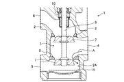
- FIG. 5 is a cross-sectional view showing the exhaust gas recirculation valve 1A according to the first embodiment.
- FIG. 6 is a partial cross-sectional perspective view showing the configuration of the exhaust gas recirculation valve 1A, and only the housing 2 is shown in cross section.
- the exhaust gas recirculation valve 1A includes a cover member 12 in addition to the components of the exhaust gas recirculation valve 1 in order to prevent the generation of erosion and collusion due to the collision of the exhaust gas described above.
- the cover member 12 is, for example, a member made of stainless steel and is provided in front of the inner wall surface 2A of the housing 2 facing the exhaust gas outlet 5.
- the cover member 12 is composed of a cover portion 13 and a support portion 14. As shown in FIG. 6, the cover portion 13 is a plate-shaped member arranged in front of the inner wall surface 2A in a state of being supported by the support portion 14.
- the support portion 14 is a ring-shaped member integrally formed with the cover portion 13.
- the plug member 11 is a member having a disk portion which is the bottom surface of the housing 2 and a cylindrical portion extending in the axial direction from the peripheral edge portion of the disk portion. Further, in the hole portion in the housing 2 to which the plug member 11 is attached, a flange portion 2B is provided at the opening peripheral portion on the inner side of the housing 2. The flange portion 2B is a portion of the hole portion protruding from the opening peripheral edge portion, and the opening diameter of the flange portion 2B is smaller than that of the disk portion of the plug member 11.
- the outer diameter of the support portion 14 is smaller than the inner diameter of the hole portion of the housing 2 to which the plug member 11 is attached, and is larger than the opening diameter of the flange portion 2B.
- the cover member 12 is inserted into the hole of the housing 2 until the support portion 14 comes into contact with the flange portion 2B so that the cover portion 13 faces the front of the inner wall surface 2A.
- the disk portion contacts the support portion 14 with the disk portion facing the inside of the housing 2 and the inner wall surface of the hole portion of the housing 2 and the outer peripheral portion of the cylindrical portion are in contact with each other. It is inserted into the hole of the housing 2 until it is closed. As a result, as shown in FIG. 5, the cover member 12 is sandwiched between the housing 2 and the plug member 11 and fixed to the housing 2.
- the cover portion 13 Since the cover portion 13 is arranged in front of the inner wall surface 2A, the flow of the exhaust gas indicated by the arrow A toward the inner wall surface 2A in FIG. 4 is blocked by the cover portion 13. As a result, the impact pressure of the exhaust gas colliding with the inner wall surface 2A of the housing 2 is alleviated, and the generation of erosion is suppressed. Further, the stainless steel cover member 12 suppresses the exhaust gas containing a large amount of water vapor component from directly hitting the cast iron housing 2, and also suppresses the occurrence of corrosion. As a result, the exhaust gas recirculation valve 1A can prevent damage to the inner wall surface 2A of the housing 2 due to the collision of the exhaust gas.
- the exhaust gas flowing in when the valve is opened is shown in FIG.
- the flow velocity is smaller than the exhaust gas toward the inner wall surface 2A.
- the impact pressure generated by the collision of the exhaust gas with the inner wall surface is proportional to the flow velocity of the exhaust gas. Therefore, when the exhaust gas collides with the inner wall surface 2A facing the exhaust gas outlet 5, a larger impact pressure is generated than the inner wall surface on the side closer to the exhaust gas outlet 5. Therefore, the cover member 12 is arranged in front of the inner wall surface 2A in order to block the flow of the exhaust gas colliding with the inner wall surface 2A.
- the exhaust gas recirculation valve 1A may be a poppet type valve.
- the exhaust gas recirculation valve 1A may be a poppet-type valve having one valve body 7 or a poppet-type valve having three or more valve bodies 7.
- the housing 2 is provided with a coolant circuit 15.
- the coolant circuit 15 is a flow path through which the coolant flows.
- the coolant contains, for example, ethylene glycol as a main component, and ethylene glycol has a characteristic that it is easy to warm and difficult to cool.
- FIG. 7 is a cross-sectional view showing an exhaust gas recirculation valve 1B, which is a modified example of the exhaust gas recirculation valve 1A.
- the exhaust gas recirculation valve 1B includes a cover member 12A instead of the cover member 12 included in the exhaust gas recirculation valve 1A.
- the cover member 12A is, for example, a member made of stainless steel, and is provided in front of the inner wall surface 2A of the housing 2 like the cover member 12.
- the cover member 12A is composed of a cover portion 13 and a support portion 14A.
- the cover portion 13 is a plate-shaped member arranged in front of the inner wall surface 2A while being supported by the support portion 14A.
- the support portion 14A is a member that functions as the plug member 11 shown in FIG. That is, as shown in FIG. 7, the support portion 14A is a member having a disk portion that is the bottom surface of the housing 2 and a cylindrical portion that extends in the axial direction from the peripheral edge portion of the disk portion.
- the cover portion 13 is integrally formed with the disk portion of the support portion 14A.
- the disk portion of the support portion 14A faces the inside of the housing 2, and the disk portion contacts the flange portion 2B in a state where the inner wall surface of the hole portion of the housing 2 and the outer peripheral portion of the cylindrical portion are in contact with each other. It is inserted into the hole of the housing 2 until it is closed. As a result, the cover member 12A is fixed to the housing 2. Since the cover member 12A also functions as the plug member 11, the increase in the number of parts can be suppressed.
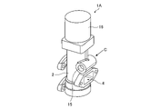
- FIG. 8 is a perspective view showing the appearance of the exhaust gas recirculation valve 1A.
- the drive source 16 is attached to the housing 2.
- the drive source 16 has a DC motor and a mechanism for converting the rotational motion of the DC motor into a linear motion of the output shaft.
- the drive source 16 is an actuator that directly moves the valve shaft 9 shown in FIGS. 5 and 6 in the axial direction.
- the coolant circuit 15 is a straight pipe flow path. The coolant flows through the straight pipe coolant circuit 15 as shown by the arrow C.
- the coolant circuit 15 when the coolant circuit is bent, the coolant collides with the inner wall surface at the bent portion of the coolant circuit.
- the coolant collides with the inner wall surface of the bent portion in a fast flow erosion or corrosion occurs also inside the coolant circuit. Therefore, as shown in FIG. 8, by forming the coolant circuit 15 in a straight pipe structure, it is possible to prevent the coolant from colliding with the inner wall surface of the coolant circuit 15 in a fast flow, and to prevent the occurrence of erosion and corrosion.
- the exhaust gas recirculation valve 1A has a valve body 7 that is driven in the axial direction to open and close the exhaust gas passage 3 and an exhaust gas passage 3 inside, and has an exhaust gas passage.
- a cover member provided in front of a housing 2 in which the exhaust gas outlet 5 connected to 3 is provided in a direction orthogonal to the axial direction of the valve body 7 and an inner wall surface 2A of the housing 2 facing the exhaust gas outlet 5. 12 and. Since the flow of the exhaust gas toward the inner wall surface 2A of the housing 2 is blocked by the cover member 12, damage to the inner wall surface 2A of the housing 2 due to the collision of the exhaust gas can be prevented.
- the cover member 12 is sandwiched between the housing 2 and the plug member 11.
- the cover member 12 can be fixed to the housing 2 by using the existing plug member 11. As a result, the increase in the number of parts required for attaching the cover member 12 can be suppressed. Further, the cover member 12 can be easily attached to the housing 2 by the same procedure as the plug member 11.
- the cover member 12A is integrally formed with the support portion 14A which is a plug member. Since the cover member 12A also functions as the plug member 11, the increase in parts required for attaching the cover member 12A can be suppressed. Further, the cover member 12A can be easily attached to the housing 2 in the same procedure as the plug member 11.
- the exhaust gas recirculation valve according to the present disclosure can be used, for example, in an internal combustion engine using natural gas as a combustible.
Landscapes
- Engineering & Computer Science (AREA)
- General Engineering & Computer Science (AREA)
- Mechanical Engineering (AREA)
- Health & Medical Sciences (AREA)
- Toxicology (AREA)
- Chemical & Material Sciences (AREA)
- Combustion & Propulsion (AREA)
- Lift Valve (AREA)
- Exhaust-Gas Circulating Devices (AREA)
- Valve Housings (AREA)
Abstract
Une soupape de recirculation de gaz d'échappement (1A) comprend : un corps de soupape (7) pour ouvrir/fermer un passage de gaz d'échappement (3) en étant entraîné dans la direction axiale ; un boîtier (2) ayant le passage de gaz d'échappement (3) à l'intérieur et pourvu d'une sortie de gaz d'échappement (5) communiquant avec le passage de gaz d'échappement (3), ladite sortie de gaz d'échappement étant définie dans une direction perpendiculaire à la direction axiale du corps de soupape (7) ; et un élément de couvercle (12) disposé devant une surface de paroi interne (2A) du boîtier (2) opposée à la sortie de gaz d'échappement (5).
Priority Applications (3)
| Application Number | Priority Date | Filing Date | Title |
|---|---|---|---|
| JP2022556332A JP7237251B2 (ja) | 2020-10-22 | 2020-10-22 | 排気ガス再循環バルブ |
| PCT/JP2020/039742 WO2022085157A1 (fr) | 2020-10-22 | 2020-10-22 | Soupape de recirculation de gaz d'échappement |
| CN202080106075.1A CN116324239A (zh) | 2020-10-22 | 2020-10-22 | 废气再循环阀 |
Applications Claiming Priority (1)
| Application Number | Priority Date | Filing Date | Title |
|---|---|---|---|
| PCT/JP2020/039742 WO2022085157A1 (fr) | 2020-10-22 | 2020-10-22 | Soupape de recirculation de gaz d'échappement |
Publications (1)
| Publication Number | Publication Date |
|---|---|
| WO2022085157A1 true WO2022085157A1 (fr) | 2022-04-28 |
Family
ID=81289827
Family Applications (1)
| Application Number | Title | Priority Date | Filing Date |
|---|---|---|---|
| PCT/JP2020/039742 WO2022085157A1 (fr) | 2020-10-22 | 2020-10-22 | Soupape de recirculation de gaz d'échappement |
Country Status (3)
| Country | Link |
|---|---|
| JP (1) | JP7237251B2 (fr) |
| CN (1) | CN116324239A (fr) |
| WO (1) | WO2022085157A1 (fr) |
Citations (5)
| Publication number | Priority date | Publication date | Assignee | Title |
|---|---|---|---|---|
| US20010023688A1 (en) * | 1999-03-11 | 2001-09-27 | Robert Meilinger | Electromechanically actuated solenoid exhaust gas recirculation valve |
| JP2004340053A (ja) * | 2003-05-16 | 2004-12-02 | Denso Corp | 排気ガス再循環装置用バルブ |
| JP2010190252A (ja) * | 2009-02-16 | 2010-09-02 | Yamatake Corp | 弁装置 |
| WO2017216838A1 (fr) * | 2016-06-13 | 2017-12-21 | 三菱電機株式会社 | Soupape de recirculation de gaz d'échappement |
| WO2019244346A1 (fr) * | 2018-06-22 | 2019-12-26 | 三菱電機株式会社 | Soupape de recirculation de gaz d'échappement |
-
2020
- 2020-10-22 JP JP2022556332A patent/JP7237251B2/ja active Active
- 2020-10-22 CN CN202080106075.1A patent/CN116324239A/zh active Pending
- 2020-10-22 WO PCT/JP2020/039742 patent/WO2022085157A1/fr active Application Filing
Patent Citations (5)
| Publication number | Priority date | Publication date | Assignee | Title |
|---|---|---|---|---|
| US20010023688A1 (en) * | 1999-03-11 | 2001-09-27 | Robert Meilinger | Electromechanically actuated solenoid exhaust gas recirculation valve |
| JP2004340053A (ja) * | 2003-05-16 | 2004-12-02 | Denso Corp | 排気ガス再循環装置用バルブ |
| JP2010190252A (ja) * | 2009-02-16 | 2010-09-02 | Yamatake Corp | 弁装置 |
| WO2017216838A1 (fr) * | 2016-06-13 | 2017-12-21 | 三菱電機株式会社 | Soupape de recirculation de gaz d'échappement |
| WO2019244346A1 (fr) * | 2018-06-22 | 2019-12-26 | 三菱電機株式会社 | Soupape de recirculation de gaz d'échappement |
Also Published As
| Publication number | Publication date |
|---|---|
| JPWO2022085157A1 (fr) | 2022-04-28 |
| JP7237251B2 (ja) | 2023-03-10 |
| CN116324239A (zh) | 2023-06-23 |
Similar Documents
| Publication | Publication Date | Title |
|---|---|---|
| US11156151B2 (en) | Regulating device for an exhaust turbocharger | |
| JP6062129B2 (ja) | 流体制御バルブ | |
| JP6464860B2 (ja) | 排気ガス再循環装置 | |
| JP2007107389A (ja) | エンジンのegrバルブ装置 | |
| US9915208B2 (en) | Flap device for an internal combustion engine | |
| JP6091364B2 (ja) | 排気ガス再循環バルブ | |
| US7204240B2 (en) | Integrated valve | |
| WO2022085157A1 (fr) | Soupape de recirculation de gaz d'échappement | |
| JP5074317B2 (ja) | 流路切替弁 | |
| JP5981411B2 (ja) | 自動車の排ガス流動用バイパス弁 | |
| EP3090161B1 (fr) | Turbocompresseur comportant une étanchéité de soupape de dérivation améliorée | |
| JP2010001855A (ja) | 内燃機関の吸気装置 | |
| JP2006313011A (ja) | 流量調節弁および流量調節弁用のブシュ | |
| JP6501975B2 (ja) | 排気ガス再循環バルブ | |
| JP7154460B2 (ja) | 排気ガス再循環バルブ | |
| JP6709923B1 (ja) | ブローオフバルブ用のアダプター | |
| JP2005207360A (ja) | Egrバルブ | |
| JP2012172519A (ja) | フラップバルブ | |
| JP4767232B2 (ja) | 排気流路バルブ | |
| JP4528719B2 (ja) | ディーゼルエンジン | |
| KR101825106B1 (ko) | 바이패스밸브 조립체 | |
| JP5858819B2 (ja) | Egrクーラバイパスバルブ | |
| JP2019210905A (ja) | 排気ガス再循環バルブ | |
| JP2022035028A (ja) | Egr弁 | |
| JP2011122659A (ja) | バタフライバルブ |
Legal Events
| Date | Code | Title | Description |
|---|---|---|---|
| 121 | Ep: the epo has been informed by wipo that ep was designated in this application |
Ref document number: 20958709 Country of ref document: EP Kind code of ref document: A1 |
|
| ENP | Entry into the national phase |
Ref document number: 2022556332 Country of ref document: JP Kind code of ref document: A |
|
| NENP | Non-entry into the national phase |
Ref country code: DE |
|
| 122 | Ep: pct application non-entry in european phase |
Ref document number: 20958709 Country of ref document: EP Kind code of ref document: A1 |