WO2022085157A1 - Exhaust gas recirculation valve - Google Patents
Exhaust gas recirculation valve Download PDFInfo
- Publication number
- WO2022085157A1 WO2022085157A1 PCT/JP2020/039742 JP2020039742W WO2022085157A1 WO 2022085157 A1 WO2022085157 A1 WO 2022085157A1 JP 2020039742 W JP2020039742 W JP 2020039742W WO 2022085157 A1 WO2022085157 A1 WO 2022085157A1
- Authority
- WO
- WIPO (PCT)
- Prior art keywords
- exhaust gas
- housing
- recirculation valve
- gas recirculation
- wall surface
- Prior art date
Links
Images


Classifications
-
- F—MECHANICAL ENGINEERING; LIGHTING; HEATING; WEAPONS; BLASTING
- F02—COMBUSTION ENGINES; HOT-GAS OR COMBUSTION-PRODUCT ENGINE PLANTS
- F02M—SUPPLYING COMBUSTION ENGINES IN GENERAL WITH COMBUSTIBLE MIXTURES OR CONSTITUENTS THEREOF
- F02M26/00—Engine-pertinent apparatus for adding exhaust gases to combustion-air, main fuel or fuel-air mixture, e.g. by exhaust gas recirculation [EGR] systems
- F02M26/65—Constructional details of EGR valves
- F02M26/74—Protection from damage, e.g. shielding means
-
- F—MECHANICAL ENGINEERING; LIGHTING; HEATING; WEAPONS; BLASTING
- F16—ENGINEERING ELEMENTS AND UNITS; GENERAL MEASURES FOR PRODUCING AND MAINTAINING EFFECTIVE FUNCTIONING OF MACHINES OR INSTALLATIONS; THERMAL INSULATION IN GENERAL
- F16K—VALVES; TAPS; COCKS; ACTUATING-FLOATS; DEVICES FOR VENTING OR AERATING
- F16K1/00—Lift valves or globe valves, i.e. cut-off apparatus with closure members having at least a component of their opening and closing motion perpendicular to the closing faces
- F16K1/32—Details
-
- Y—GENERAL TAGGING OF NEW TECHNOLOGICAL DEVELOPMENTS; GENERAL TAGGING OF CROSS-SECTIONAL TECHNOLOGIES SPANNING OVER SEVERAL SECTIONS OF THE IPC; TECHNICAL SUBJECTS COVERED BY FORMER USPC CROSS-REFERENCE ART COLLECTIONS [XRACs] AND DIGESTS
- Y02—TECHNOLOGIES OR APPLICATIONS FOR MITIGATION OR ADAPTATION AGAINST CLIMATE CHANGE
- Y02T—CLIMATE CHANGE MITIGATION TECHNOLOGIES RELATED TO TRANSPORTATION
- Y02T10/00—Road transport of goods or passengers
- Y02T10/10—Internal combustion engine [ICE] based vehicles
- Y02T10/12—Improving ICE efficiencies
Definitions
- This disclosure relates to an exhaust gas recirculation valve.
- Patent Document 1 describes an exhaust gas recirculation valve including a valve housing having a gas communication passage inside and a valve driven in the axial direction to open and close the gas communication passage.
- an object of the present invention is to obtain an exhaust gas recirculation valve capable of preventing damage to the inner wall surface of the housing due to an exhaust gas collision.
- the exhaust gas recirculation valve has a valve body that is driven in the axial direction to open and close the exhaust gas passage, and an exhaust gas passage inside, and the exhaust gas outlet connected to the exhaust gas passage is the valve body.
- a housing provided in a direction orthogonal to the axial direction and a cover member provided in front of the inner wall surface of the housing facing the exhaust gas outlet are provided.
- FIG. 1 It is sectional drawing which shows the exhaust gas recirculation valve in a closed state. It is sectional drawing which shows the exhaust gas recirculation valve in an open state. It is an image diagram which shows the fluid analysis result of the exhaust gas recirculation valve in an open state. It is an image diagram which shows only the flow velocity in the Y direction of FIG. It is sectional drawing which shows the exhaust gas recirculation valve which concerns on Embodiment 1.
- FIG. It is a partial sectional perspective view which shows the structure of the exhaust gas recirculation valve of FIG. It is sectional drawing which shows the modification of the exhaust gas recirculation valve which concerns on Embodiment 1.
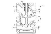
- FIG. 1 is a cross-sectional view showing an exhaust gas recirculation valve 1 in a closed state.
- FIG. 2 is a cross-sectional view showing an exhaust gas recirculation valve 1 in an open state.
- the housing 2 of the exhaust gas recirculation valve 1 is formed of, for example, cast iron, and the exhaust gas passage 3 is formed inside the housing 2 as shown in FIGS. 1 and 2.
- the exhaust gas passage 3 is connected to the exhaust gas inlet 4, the two exhaust gas outlets 5, and the exhaust gas outlet 6.
- the exhaust gas recirculation valve 1 supplies, for example, a path for exhaust gas to flow out from the exhaust gas inlet 4 to the exhaust gas outlet 5 and an exhaust gas from the exhaust gas inlet 4 to the exhaust gas outlet 6 in the exhaust gas passage 3. It is a so-called double poppet type valve that opens and closes the outflow path.
- the exhaust gas passage 3 is closed when the valve body 7 comes into contact with the valve seat 8, and the exhaust gas passage 3 is separated from the valve seat 8 as shown in FIG. 3 is in the open state.
- the valve body 7 is fixed to the valve shaft 9 and moves in the axial direction integrally with the valve shaft 9.
- a drive source (not shown in FIGS. 1 and 2) is attached to the housing 2.
- the drive source has a DC motor and a mechanism for converting the rotational motion of the DC motor into a linear motion of the output shaft.
- the valve body 7 moves along the axial direction due to the direct movement of the valve shaft 9 in the axial direction by the drive source.
- the valve shaft 9 is supported by a bearing 10.
- the plug member 11 is a member that closes the housing 2 from the axial direction of the valve body 7.
- the housing 2 has, for example, a hole in the axial direction of the valve body 7. In the manufacture of the exhaust gas recirculation valve 1, the valve seat 8 is machined through this hole.
- the plug member 11 is attached to the hole of the housing 2 and closes the exhaust gas passage 3 of the housing 2 from the axial direction of the valve body 7.
- the exhaust gas outlet 5 is provided at a position orthogonal to the axial direction of the valve body 7.
- the route from the exhaust gas inlet 4 to the exhaust gas outlet 5 in the exhaust gas passage 3 is as shown by an arrow A. Exhaust gas flows in.
- FIG. 3 is an image diagram showing the fluid analysis result of the exhaust gas recirculation valve 1 in the open state, and shows the flow velocity distribution of the exhaust gas.
- FIG. 4 is an image diagram showing only the flow velocity distribution in the Y direction of FIG. In the flow velocity distributions of FIGS. 3 and 4, the darker the image showing the flow of the exhaust gas, the faster the flow of the exhaust gas.
- FIG. 4 when the exhaust gas recirculation valve 1 is opened, the exhaust gas indicated by the arrow A collides with the inner wall surface 2A of the housing 2 facing the exhaust gas outlet 5 at a high speed. are doing.
- the exhaust gas collides with the inner wall surface of the housing 2, an impact pressure is generated by changing the fluid momentum of the exhaust gas at the moment of the collision.
- the inner wall surface of the housing is gradually scraped off by erosion caused by the impact pressure of the generated exhaust gas.
- the exhaust gas contains many water vapor components. In this case, erosion due to the collision of the exhaust gas and corrosion due to the water vapor component of the exhaust gas may occur on the inner wall surface 2A of the cast iron housing 2.
- FIG. 5 is a cross-sectional view showing the exhaust gas recirculation valve 1A according to the first embodiment.
- FIG. 6 is a partial cross-sectional perspective view showing the configuration of the exhaust gas recirculation valve 1A, and only the housing 2 is shown in cross section.
- the exhaust gas recirculation valve 1A includes a cover member 12 in addition to the components of the exhaust gas recirculation valve 1 in order to prevent the generation of erosion and collusion due to the collision of the exhaust gas described above.
- the cover member 12 is, for example, a member made of stainless steel and is provided in front of the inner wall surface 2A of the housing 2 facing the exhaust gas outlet 5.
- the cover member 12 is composed of a cover portion 13 and a support portion 14. As shown in FIG. 6, the cover portion 13 is a plate-shaped member arranged in front of the inner wall surface 2A in a state of being supported by the support portion 14.
- the support portion 14 is a ring-shaped member integrally formed with the cover portion 13.
- the plug member 11 is a member having a disk portion which is the bottom surface of the housing 2 and a cylindrical portion extending in the axial direction from the peripheral edge portion of the disk portion. Further, in the hole portion in the housing 2 to which the plug member 11 is attached, a flange portion 2B is provided at the opening peripheral portion on the inner side of the housing 2. The flange portion 2B is a portion of the hole portion protruding from the opening peripheral edge portion, and the opening diameter of the flange portion 2B is smaller than that of the disk portion of the plug member 11.
- the outer diameter of the support portion 14 is smaller than the inner diameter of the hole portion of the housing 2 to which the plug member 11 is attached, and is larger than the opening diameter of the flange portion 2B.
- the cover member 12 is inserted into the hole of the housing 2 until the support portion 14 comes into contact with the flange portion 2B so that the cover portion 13 faces the front of the inner wall surface 2A.
- the disk portion contacts the support portion 14 with the disk portion facing the inside of the housing 2 and the inner wall surface of the hole portion of the housing 2 and the outer peripheral portion of the cylindrical portion are in contact with each other. It is inserted into the hole of the housing 2 until it is closed. As a result, as shown in FIG. 5, the cover member 12 is sandwiched between the housing 2 and the plug member 11 and fixed to the housing 2.
- the cover portion 13 Since the cover portion 13 is arranged in front of the inner wall surface 2A, the flow of the exhaust gas indicated by the arrow A toward the inner wall surface 2A in FIG. 4 is blocked by the cover portion 13. As a result, the impact pressure of the exhaust gas colliding with the inner wall surface 2A of the housing 2 is alleviated, and the generation of erosion is suppressed. Further, the stainless steel cover member 12 suppresses the exhaust gas containing a large amount of water vapor component from directly hitting the cast iron housing 2, and also suppresses the occurrence of corrosion. As a result, the exhaust gas recirculation valve 1A can prevent damage to the inner wall surface 2A of the housing 2 due to the collision of the exhaust gas.
- the exhaust gas flowing in when the valve is opened is shown in FIG.
- the flow velocity is smaller than the exhaust gas toward the inner wall surface 2A.
- the impact pressure generated by the collision of the exhaust gas with the inner wall surface is proportional to the flow velocity of the exhaust gas. Therefore, when the exhaust gas collides with the inner wall surface 2A facing the exhaust gas outlet 5, a larger impact pressure is generated than the inner wall surface on the side closer to the exhaust gas outlet 5. Therefore, the cover member 12 is arranged in front of the inner wall surface 2A in order to block the flow of the exhaust gas colliding with the inner wall surface 2A.
- the exhaust gas recirculation valve 1A may be a poppet type valve.
- the exhaust gas recirculation valve 1A may be a poppet-type valve having one valve body 7 or a poppet-type valve having three or more valve bodies 7.
- the housing 2 is provided with a coolant circuit 15.
- the coolant circuit 15 is a flow path through which the coolant flows.
- the coolant contains, for example, ethylene glycol as a main component, and ethylene glycol has a characteristic that it is easy to warm and difficult to cool.
- FIG. 7 is a cross-sectional view showing an exhaust gas recirculation valve 1B, which is a modified example of the exhaust gas recirculation valve 1A.
- the exhaust gas recirculation valve 1B includes a cover member 12A instead of the cover member 12 included in the exhaust gas recirculation valve 1A.
- the cover member 12A is, for example, a member made of stainless steel, and is provided in front of the inner wall surface 2A of the housing 2 like the cover member 12.
- the cover member 12A is composed of a cover portion 13 and a support portion 14A.
- the cover portion 13 is a plate-shaped member arranged in front of the inner wall surface 2A while being supported by the support portion 14A.
- the support portion 14A is a member that functions as the plug member 11 shown in FIG. That is, as shown in FIG. 7, the support portion 14A is a member having a disk portion that is the bottom surface of the housing 2 and a cylindrical portion that extends in the axial direction from the peripheral edge portion of the disk portion.
- the cover portion 13 is integrally formed with the disk portion of the support portion 14A.
- the disk portion of the support portion 14A faces the inside of the housing 2, and the disk portion contacts the flange portion 2B in a state where the inner wall surface of the hole portion of the housing 2 and the outer peripheral portion of the cylindrical portion are in contact with each other. It is inserted into the hole of the housing 2 until it is closed. As a result, the cover member 12A is fixed to the housing 2. Since the cover member 12A also functions as the plug member 11, the increase in the number of parts can be suppressed.
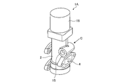
- FIG. 8 is a perspective view showing the appearance of the exhaust gas recirculation valve 1A.
- the drive source 16 is attached to the housing 2.
- the drive source 16 has a DC motor and a mechanism for converting the rotational motion of the DC motor into a linear motion of the output shaft.
- the drive source 16 is an actuator that directly moves the valve shaft 9 shown in FIGS. 5 and 6 in the axial direction.
- the coolant circuit 15 is a straight pipe flow path. The coolant flows through the straight pipe coolant circuit 15 as shown by the arrow C.
- the coolant circuit 15 when the coolant circuit is bent, the coolant collides with the inner wall surface at the bent portion of the coolant circuit.
- the coolant collides with the inner wall surface of the bent portion in a fast flow erosion or corrosion occurs also inside the coolant circuit. Therefore, as shown in FIG. 8, by forming the coolant circuit 15 in a straight pipe structure, it is possible to prevent the coolant from colliding with the inner wall surface of the coolant circuit 15 in a fast flow, and to prevent the occurrence of erosion and corrosion.
- the exhaust gas recirculation valve 1A has a valve body 7 that is driven in the axial direction to open and close the exhaust gas passage 3 and an exhaust gas passage 3 inside, and has an exhaust gas passage.
- a cover member provided in front of a housing 2 in which the exhaust gas outlet 5 connected to 3 is provided in a direction orthogonal to the axial direction of the valve body 7 and an inner wall surface 2A of the housing 2 facing the exhaust gas outlet 5. 12 and. Since the flow of the exhaust gas toward the inner wall surface 2A of the housing 2 is blocked by the cover member 12, damage to the inner wall surface 2A of the housing 2 due to the collision of the exhaust gas can be prevented.
- the cover member 12 is sandwiched between the housing 2 and the plug member 11.
- the cover member 12 can be fixed to the housing 2 by using the existing plug member 11. As a result, the increase in the number of parts required for attaching the cover member 12 can be suppressed. Further, the cover member 12 can be easily attached to the housing 2 by the same procedure as the plug member 11.
- the cover member 12A is integrally formed with the support portion 14A which is a plug member. Since the cover member 12A also functions as the plug member 11, the increase in parts required for attaching the cover member 12A can be suppressed. Further, the cover member 12A can be easily attached to the housing 2 in the same procedure as the plug member 11.
- the exhaust gas recirculation valve according to the present disclosure can be used, for example, in an internal combustion engine using natural gas as a combustible.
Abstract
An exhaust gas recirculation valve (1A) comprises: a valve body (7) for opening/closing an exhaust gas passage (3) by being driven in the axial direction; a housing (2) having the exhaust gas passage (3) in the inside and provided with an exhaust gas outlet (5) communicating with the exhaust gas passage (3), said exhaust gas outlet being set in a direction perpendicular to the axial direction of the valve body (7); and a cover member (12) provided in front of an inner wall surface (2A) of the housing (2) opposed to the exhaust gas outlet (5).
Description
本開示は、排気ガス再循環バルブに関する。
This disclosure relates to an exhaust gas recirculation valve.
内燃機関で発生した排気ガスの一部を吸気側へ導いて循環させる排気ガス再循環バルブが知られている。例えば、特許文献1には、ガス連通路を内部に有するバルブハウジングと、軸線方向に駆動してガス連通路を開閉するバルブとを備えた排気ガス再循環バルブが記載されている。
An exhaust gas recirculation valve is known that guides a part of the exhaust gas generated in the internal combustion engine to the intake side and circulates it. For example, Patent Document 1 describes an exhaust gas recirculation valve including a valve housing having a gas communication passage inside and a valve driven in the axial direction to open and close the gas communication passage.
排気ガス通路が開状態になると、ハウジングの排気ガス流出口に対向する内壁面には、速い流れの排気ガスが衝突する。このため、内壁面に排気ガスの衝突によるエロージョンまたはコロージョンが発生するという課題があった。
When the exhaust gas passage is opened, the fast-flowing exhaust gas collides with the inner wall surface facing the exhaust gas outlet of the housing. Therefore, there is a problem that erosion or corrosion occurs on the inner wall surface due to the collision of exhaust gas.
本開示は上記課題を解決するものであり、排気ガスの衝突によるハウジングの内壁面の損傷を防ぐことができる排気ガス再循環バルブを得ることを目的とする。
The present disclosure solves the above-mentioned problems, and an object of the present invention is to obtain an exhaust gas recirculation valve capable of preventing damage to the inner wall surface of the housing due to an exhaust gas collision.
本開示に係る排気ガス再循環バルブは、軸線方向に駆動して排気ガス通路を開閉する弁体と、排気ガス通路を内部に有し、排気ガス通路につながった排気ガス流出口が弁体の軸線方向に直交する方向に設けられたハウジングと、排気ガス流出口に対向するハウジングの内壁面の前方に設けられたカバー部材とを備える。
The exhaust gas recirculation valve according to the present disclosure has a valve body that is driven in the axial direction to open and close the exhaust gas passage, and an exhaust gas passage inside, and the exhaust gas outlet connected to the exhaust gas passage is the valve body. A housing provided in a direction orthogonal to the axial direction and a cover member provided in front of the inner wall surface of the housing facing the exhaust gas outlet are provided.
本開示によれば、ハウジングの内壁面に向かう排気ガスの流れが、カバー部材によって遮断されるので、排気ガスの衝突によるハウジングの内壁面の損傷を防ぐことができる。
According to the present disclosure, since the flow of the exhaust gas toward the inner wall surface of the housing is blocked by the cover member, it is possible to prevent damage to the inner wall surface of the housing due to the collision of the exhaust gas.
実施の形態1.
図1は、閉状態の排気ガス再循環バルブ1を示す断面図である。また、図2は、開状態の排気ガス再循環バルブ1を示す断面図である。排気ガス再循環バルブ1のハウジング2は、例えば、鋳鉄によって形成され、排気ガス通路3は、図1および図2に示すように、ハウジング2の内部に形成されている。排気ガス通路3は、排気ガス流入口4と、2つの排気ガス流出口5および排気ガス流出口6とにつながっている。 Embodiment 1.
FIG. 1 is a cross-sectional view showing an exhaust gas recirculation valve 1 in a closed state. Further, FIG. 2 is a cross-sectional view showing an exhaust gas recirculation valve 1 in an open state. Thehousing 2 of the exhaust gas recirculation valve 1 is formed of, for example, cast iron, and the exhaust gas passage 3 is formed inside the housing 2 as shown in FIGS. 1 and 2. The exhaust gas passage 3 is connected to the exhaust gas inlet 4, the two exhaust gas outlets 5, and the exhaust gas outlet 6.
図1は、閉状態の排気ガス再循環バルブ1を示す断面図である。また、図2は、開状態の排気ガス再循環バルブ1を示す断面図である。排気ガス再循環バルブ1のハウジング2は、例えば、鋳鉄によって形成され、排気ガス通路3は、図1および図2に示すように、ハウジング2の内部に形成されている。排気ガス通路3は、排気ガス流入口4と、2つの排気ガス流出口5および排気ガス流出口6とにつながっている。 Embodiment 1.
FIG. 1 is a cross-sectional view showing an exhaust gas recirculation valve 1 in a closed state. Further, FIG. 2 is a cross-sectional view showing an exhaust gas recirculation valve 1 in an open state. The
排気ガス再循環バルブ1は、例えば、排気ガス通路3における、排気ガス流入口4から排気ガス流出口5へ排気ガスを流出する経路と排気ガス流入口4から排気ガス流出口6へ排気ガスを流出する経路とを開閉する、いわゆるダブルポペット式のバルブである。
The exhaust gas recirculation valve 1 supplies, for example, a path for exhaust gas to flow out from the exhaust gas inlet 4 to the exhaust gas outlet 5 and an exhaust gas from the exhaust gas inlet 4 to the exhaust gas outlet 6 in the exhaust gas passage 3. It is a so-called double poppet type valve that opens and closes the outflow path.
図1に示すように、弁体7が弁座8に接触することにより、排気ガス通路3が閉状態となり、図2示すように、弁体7が弁座8から離れることにより、排気ガス通路3が開状態となる。弁体7は、弁軸9に固定され、弁軸9と一体的に軸線方向に移動する。ハウジング2には、図1および図2において図示を省略した駆動源が取り付けられる。駆動源は、直流モータと、この直流モータの回転運動を出力軸の直動に変換する機構を有している。駆動源によって弁軸9が軸線方向に直動することによって、弁体7は、軸線方向に沿って移動する。弁軸9は、軸受け10によって支持されている。
As shown in FIG. 1, the exhaust gas passage 3 is closed when the valve body 7 comes into contact with the valve seat 8, and the exhaust gas passage 3 is separated from the valve seat 8 as shown in FIG. 3 is in the open state. The valve body 7 is fixed to the valve shaft 9 and moves in the axial direction integrally with the valve shaft 9. A drive source (not shown in FIGS. 1 and 2) is attached to the housing 2. The drive source has a DC motor and a mechanism for converting the rotational motion of the DC motor into a linear motion of the output shaft. The valve body 7 moves along the axial direction due to the direct movement of the valve shaft 9 in the axial direction by the drive source. The valve shaft 9 is supported by a bearing 10.
プラグ部材11は、弁体7の軸線方向からハウジング2を閉塞する部材である。ハウジング2は、例えば、弁体7の軸線方向に孔部を有する。排気ガス再循環バルブ1の製造において、弁座8は、この孔部を通じて加工される。プラグ部材11は、ハウジング2の孔部に取り付けられて、弁体7の軸線方向からハウジング2の排気ガス通路3を閉塞する。
The plug member 11 is a member that closes the housing 2 from the axial direction of the valve body 7. The housing 2 has, for example, a hole in the axial direction of the valve body 7. In the manufacture of the exhaust gas recirculation valve 1, the valve seat 8 is machined through this hole. The plug member 11 is attached to the hole of the housing 2 and closes the exhaust gas passage 3 of the housing 2 from the axial direction of the valve body 7.
ハウジング2において、排気ガス流出口5は、弁体7の軸線方向に直交する方向の箇所に設けられる。弁体7が弁座8から離れて排気ガス再循環バルブ1が開状態になると、排気ガス通路3における排気ガス流入口4から排気ガス流出口5への経路は、矢印Aで示すように、排気ガスが流れ込む。
In the housing 2, the exhaust gas outlet 5 is provided at a position orthogonal to the axial direction of the valve body 7. When the valve body 7 is separated from the valve seat 8 and the exhaust gas recirculation valve 1 is opened, the route from the exhaust gas inlet 4 to the exhaust gas outlet 5 in the exhaust gas passage 3 is as shown by an arrow A. Exhaust gas flows in.
図3は、開状態の排気ガス再循環バルブ1の流体解析結果を示すイメージ図であり、排気ガスの流速分布を示している。図4は、図3のY方向の流速分布のみを示すイメージ図である。図3および図4の流速分布において、排気ガスの流れを示すイメージが濃い色であるほど、排気ガスの流れが速いことを示している。図4から明らかなように、排気ガス再循環バルブ1が開状態になると、矢印Aで示した排気ガスは、排気ガス流出口5に対向するハウジング2の内壁面2Aに対して速い流れで衝突している。
FIG. 3 is an image diagram showing the fluid analysis result of the exhaust gas recirculation valve 1 in the open state, and shows the flow velocity distribution of the exhaust gas. FIG. 4 is an image diagram showing only the flow velocity distribution in the Y direction of FIG. In the flow velocity distributions of FIGS. 3 and 4, the darker the image showing the flow of the exhaust gas, the faster the flow of the exhaust gas. As is clear from FIG. 4, when the exhaust gas recirculation valve 1 is opened, the exhaust gas indicated by the arrow A collides with the inner wall surface 2A of the housing 2 facing the exhaust gas outlet 5 at a high speed. are doing.
排気ガスがハウジング2の内壁面に衝突すると、衝突の瞬間に排気ガスの流体運動量が変化することによって衝撃圧が発生する。ハウジングの内壁面は、発生した排気ガスの衝撃圧に起因したエロージョンによって徐々に削り取られる。また、内燃機関が天然ガスを燃焼物とする場合、排気ガスには、多くの水蒸気成分が含まれる。この場合、鋳鉄のハウジング2の内壁面2Aには、排気ガスの衝突によるエロージョンと排気ガスの水蒸気成分によるコロージョンとが発生する可能性がある。
When the exhaust gas collides with the inner wall surface of the housing 2, an impact pressure is generated by changing the fluid momentum of the exhaust gas at the moment of the collision. The inner wall surface of the housing is gradually scraped off by erosion caused by the impact pressure of the generated exhaust gas. Further, when the internal combustion engine uses natural gas as a combustible, the exhaust gas contains many water vapor components. In this case, erosion due to the collision of the exhaust gas and corrosion due to the water vapor component of the exhaust gas may occur on the inner wall surface 2A of the cast iron housing 2.
図5は、実施の形態1に係る排気ガス再循環バルブ1Aを示す断面図である。図6は、排気ガス再循環バルブ1Aの構成を示す部分断面斜視図であり、ハウジング2のみを断面で示している。図5および図6において、図1および図2と同一の構成要素には、同一の符号が付されている。排気ガス再循環バルブ1Aは、前述した排気ガスの衝突によるエロージョンおよびコロージョンの発生を防ぐために、排気ガス再循環バルブ1の構成要素に加えて、カバー部材12を備えている。
FIG. 5 is a cross-sectional view showing the exhaust gas recirculation valve 1A according to the first embodiment. FIG. 6 is a partial cross-sectional perspective view showing the configuration of the exhaust gas recirculation valve 1A, and only the housing 2 is shown in cross section. In FIGS. 5 and 6, the same components as those in FIGS. 1 and 2 are designated by the same reference numerals. The exhaust gas recirculation valve 1A includes a cover member 12 in addition to the components of the exhaust gas recirculation valve 1 in order to prevent the generation of erosion and collusion due to the collision of the exhaust gas described above.
カバー部材12は、例えば、ステンレスによって形成された部材であり、排気ガス流出口5に対向するハウジング2の内壁面2Aの前方に設けられる。カバー部材12は、カバー部13および支持部14によって構成される。図6に示すように、カバー部13は、支持部14に支持された状態で、内壁面2Aの前方に配置される板状の部材である。支持部14は、カバー部13と一体に形成されたリング状の部材である。
The cover member 12 is, for example, a member made of stainless steel and is provided in front of the inner wall surface 2A of the housing 2 facing the exhaust gas outlet 5. The cover member 12 is composed of a cover portion 13 and a support portion 14. As shown in FIG. 6, the cover portion 13 is a plate-shaped member arranged in front of the inner wall surface 2A in a state of being supported by the support portion 14. The support portion 14 is a ring-shaped member integrally formed with the cover portion 13.
プラグ部材11は、図5および図6に示すように、ハウジング2の底面となる円板部と円板部の周縁部から軸線方向に延びた円筒部とを有する部材である。また、ハウジング2におけるプラグ部材11が取り付けられる孔部には、ハウジング2の内部側の開口周縁部にフランジ部2Bが設けられている。フランジ部2Bは、上記孔部の上記開口周縁部から張り出した部分であり、フランジ部2Bにおける開口径は、プラグ部材11の円板部よりも径が小さい。
As shown in FIGS. 5 and 6, the plug member 11 is a member having a disk portion which is the bottom surface of the housing 2 and a cylindrical portion extending in the axial direction from the peripheral edge portion of the disk portion. Further, in the hole portion in the housing 2 to which the plug member 11 is attached, a flange portion 2B is provided at the opening peripheral portion on the inner side of the housing 2. The flange portion 2B is a portion of the hole portion protruding from the opening peripheral edge portion, and the opening diameter of the flange portion 2B is smaller than that of the disk portion of the plug member 11.
支持部14の外径は、プラグ部材11が取り付けられるハウジング2の孔部の内径よりも小さく、かつ、フランジ部2Bにおける開口径よりも大きい。カバー部材12は、カバー部13が内壁面2Aの前方になる向きで、支持部14がフランジ部2Bに接触するまでハウジング2の孔部に挿入される。この後、プラグ部材11は、円板部をハウジング2の内側に向けて、ハウジング2の孔部の内壁面と円筒部の外周部とが接触した状態で、円板部が支持部14に接触するまでハウジング2の孔部に挿入される。これにより、図5に示すように、カバー部材12は、ハウジング2とプラグ部材11に挟持されて、ハウジング2に固定される。
The outer diameter of the support portion 14 is smaller than the inner diameter of the hole portion of the housing 2 to which the plug member 11 is attached, and is larger than the opening diameter of the flange portion 2B. The cover member 12 is inserted into the hole of the housing 2 until the support portion 14 comes into contact with the flange portion 2B so that the cover portion 13 faces the front of the inner wall surface 2A. After that, in the plug member 11, the disk portion contacts the support portion 14 with the disk portion facing the inside of the housing 2 and the inner wall surface of the hole portion of the housing 2 and the outer peripheral portion of the cylindrical portion are in contact with each other. It is inserted into the hole of the housing 2 until it is closed. As a result, as shown in FIG. 5, the cover member 12 is sandwiched between the housing 2 and the plug member 11 and fixed to the housing 2.
カバー部13が内壁面2Aの前方に配置されているので、図4において矢印Aで示した排気ガスの内壁面2Aへ向かう流れは、カバー部13によって遮断される。これにより、ハウジング2の内壁面2Aに衝突する排気ガスの衝撃圧が緩和され、エロージョンの発生が抑えられる。また、ステンレス製のカバー部材12によって、多くの水蒸気成分を含む排気ガスが、鋳鉄のハウジング2へ直撃することが抑えられ、コロージョンの発生も抑えられる。これにより、排気ガス再循環バルブ1Aは、排気ガスの衝突によるハウジング2の内壁面2Aの損傷を防ぐことができる。
Since the cover portion 13 is arranged in front of the inner wall surface 2A, the flow of the exhaust gas indicated by the arrow A toward the inner wall surface 2A in FIG. 4 is blocked by the cover portion 13. As a result, the impact pressure of the exhaust gas colliding with the inner wall surface 2A of the housing 2 is alleviated, and the generation of erosion is suppressed. Further, the stainless steel cover member 12 suppresses the exhaust gas containing a large amount of water vapor component from directly hitting the cast iron housing 2, and also suppresses the occurrence of corrosion. As a result, the exhaust gas recirculation valve 1A can prevent damage to the inner wall surface 2A of the housing 2 due to the collision of the exhaust gas.
なお、排気ガス流出口5に対向するハウジング2の内壁面2A以外の部分、すなわち、排気ガス流出口5に近い側の内壁面では、開弁されたときに流入する排気ガスは、図4に示したように、内壁面2Aへ向かう排気ガスよりも流速が小さい。内壁面への排気ガスの衝突により発生する衝撃圧は、排気ガスの流速に比例する。このため、排気ガス流出口5に対向する内壁面2Aには、排気ガスが衝突することにより、排気ガス流出口5に近い側の内壁面よりも大きな衝撃圧が発生する。そこで、内壁面2Aへ衝突する排気ガスの流れを遮断するために、カバー部材12は、内壁面2Aの前方に配置される。
In addition, in the portion other than the inner wall surface 2A of the housing 2 facing the exhaust gas outlet 5, that is, the inner wall surface on the side close to the exhaust gas outlet 5, the exhaust gas flowing in when the valve is opened is shown in FIG. As shown, the flow velocity is smaller than the exhaust gas toward the inner wall surface 2A. The impact pressure generated by the collision of the exhaust gas with the inner wall surface is proportional to the flow velocity of the exhaust gas. Therefore, when the exhaust gas collides with the inner wall surface 2A facing the exhaust gas outlet 5, a larger impact pressure is generated than the inner wall surface on the side closer to the exhaust gas outlet 5. Therefore, the cover member 12 is arranged in front of the inner wall surface 2A in order to block the flow of the exhaust gas colliding with the inner wall surface 2A.
なお、排気ガス再循環バルブ1Aがダブルポペット式のバルブである場合を示したが、排気ガス再循環バルブ1Aはポペット式のバルブであればよい。例えば、排気ガス再循環バルブ1Aは、弁体7が一つのポペット式のバルブであってもよいし、弁体7が3つ以上のポペット式のバルブであってもよい。
Although the case where the exhaust gas recirculation valve 1A is a double poppet type valve is shown, the exhaust gas recirculation valve 1A may be a poppet type valve. For example, the exhaust gas recirculation valve 1A may be a poppet-type valve having one valve body 7 or a poppet-type valve having three or more valve bodies 7.
ハウジング2には、図5に示すように、クーラント回路15が設けられる。クーラント回路15は、クーラントが流れる流路である。クーラントは、例えばエチレングリコールを主成分であり、エチレングリコールは、温まりやすく冷めにくいという特徴を有する。低温の環境下で内燃機関が始動された場合、クーラント回路15を流れるクーラントは、ハウジング2の壁面を介して内燃機関からの熱を吸収し、クーラントの温度は、雰囲気温度の上昇よりも先に上昇する。温まったクーラントをクーラント回路15に流すことで、クーラントからの熱によってハウジング2の内部の氷結が解除される。
As shown in FIG. 5, the housing 2 is provided with a coolant circuit 15. The coolant circuit 15 is a flow path through which the coolant flows. The coolant contains, for example, ethylene glycol as a main component, and ethylene glycol has a characteristic that it is easy to warm and difficult to cool. When the internal combustion engine is started in a low temperature environment, the coolant flowing through the coolant circuit 15 absorbs heat from the internal combustion engine through the wall surface of the housing 2, and the temperature of the coolant is prior to the rise in the ambient temperature. Rise. By flowing the warmed coolant through the coolant circuit 15, the freezing inside the housing 2 is released by the heat from the coolant.
図7は、排気ガス再循環バルブ1Aの変形例である、排気ガス再循環バルブ1Bを示す断面図である。図7において、図1および図2と同一の構成要素には、同一の符号が付されている。排気ガス再循環バルブ1Bは、排気ガス再循環バルブ1Aが備えるカバー部材12の代わりに、カバー部材12Aを備える。
FIG. 7 is a cross-sectional view showing an exhaust gas recirculation valve 1B, which is a modified example of the exhaust gas recirculation valve 1A. In FIG. 7, the same components as those in FIGS. 1 and 2 are designated by the same reference numerals. The exhaust gas recirculation valve 1B includes a cover member 12A instead of the cover member 12 included in the exhaust gas recirculation valve 1A.
カバー部材12Aは、例えば、ステンレスによって形成された部材であり、カバー部材12と同様に、ハウジング2の内壁面2Aの前方に設けられる。カバー部材12Aは、カバー部13と支持部14Aによって構成される。カバー部13は、支持部14Aに支持された状態で、内壁面2Aの前方に配置される板状の部材である。支持部14Aは、図5に示したプラグ部材11として機能する部材である。すなわち、支持部14Aは、図7に示すように、ハウジング2の底面となる円板部と、円板部の周縁部から軸線方向に延びた円筒部とを有する部材である。カバー部13は、支持部14Aの円板部と一体に形成されている。
The cover member 12A is, for example, a member made of stainless steel, and is provided in front of the inner wall surface 2A of the housing 2 like the cover member 12. The cover member 12A is composed of a cover portion 13 and a support portion 14A. The cover portion 13 is a plate-shaped member arranged in front of the inner wall surface 2A while being supported by the support portion 14A. The support portion 14A is a member that functions as the plug member 11 shown in FIG. That is, as shown in FIG. 7, the support portion 14A is a member having a disk portion that is the bottom surface of the housing 2 and a cylindrical portion that extends in the axial direction from the peripheral edge portion of the disk portion. The cover portion 13 is integrally formed with the disk portion of the support portion 14A.
カバー部材12Aは、支持部14Aの円板部をハウジング2の内側に向けて、ハウジング2の孔部の内壁面と円筒部の外周部とが接触した状態で円板部がフランジ部2Bに接触するまでハウジング2の孔部に挿入される。これにより、カバー部材12Aは、ハウジング2に固定される。カバー部材12Aは、プラグ部材11としても機能するので、部品点数の増加が抑えられる。
In the cover member 12A, the disk portion of the support portion 14A faces the inside of the housing 2, and the disk portion contacts the flange portion 2B in a state where the inner wall surface of the hole portion of the housing 2 and the outer peripheral portion of the cylindrical portion are in contact with each other. It is inserted into the hole of the housing 2 until it is closed. As a result, the cover member 12A is fixed to the housing 2. Since the cover member 12A also functions as the plug member 11, the increase in the number of parts can be suppressed.
図8は、排気ガス再循環バルブ1Aの外観を示す斜視図である。図8において、駆動源16は、ハウジング2に取り付けられる。駆動源16は、直流モータと、この直流モータの回転運動を出力軸の直動に変換する機構とを有する。駆動源16は、図5および図6に示した弁軸9を軸線方向に直動させるアクチュエータである。また、クーラント回路15は、図8に示すように、直管の流路である。クーラントは、矢印Cで示すように、直管のクーラント回路15を流れる。
FIG. 8 is a perspective view showing the appearance of the exhaust gas recirculation valve 1A. In FIG. 8, the drive source 16 is attached to the housing 2. The drive source 16 has a DC motor and a mechanism for converting the rotational motion of the DC motor into a linear motion of the output shaft. The drive source 16 is an actuator that directly moves the valve shaft 9 shown in FIGS. 5 and 6 in the axial direction. Further, as shown in FIG. 8, the coolant circuit 15 is a straight pipe flow path. The coolant flows through the straight pipe coolant circuit 15 as shown by the arrow C.
例えば、クーラント回路が屈曲している場合、クーラントは、クーラント回路の屈曲部における内壁面に衝突する。クーラントが速い流れで上記屈曲部の内壁面に衝突すると、クーラント回路の内部においてもエロージョンまたはコロージョンが発生する。そこで、図8に示すように、クーラント回路15を直管構造とすることにより、クーラントが速い流れでクーラント回路15の内壁面に衝突することが抑えられ、エロージョンおよびコロージョンの発生が防止される。
For example, when the coolant circuit is bent, the coolant collides with the inner wall surface at the bent portion of the coolant circuit. When the coolant collides with the inner wall surface of the bent portion in a fast flow, erosion or corrosion occurs also inside the coolant circuit. Therefore, as shown in FIG. 8, by forming the coolant circuit 15 in a straight pipe structure, it is possible to prevent the coolant from colliding with the inner wall surface of the coolant circuit 15 in a fast flow, and to prevent the occurrence of erosion and corrosion.
以上のように、実施の形態1に係る排気ガス再循環バルブ1Aは、軸線方向に駆動して排気ガス通路3を開閉する弁体7と、排気ガス通路3を内部に有し、排気ガス通路3につながった排気ガス流出口5が弁体7の軸線方向に直交する方向に設けられたハウジング2と、排気ガス流出口5に対向するハウジング2の内壁面2Aの前方に設けられたカバー部材12とを備える。ハウジング2の内壁面2Aに向かう排気ガスの流れがカバー部材12によって遮断されるので、排気ガスの衝突によるハウジング2の内壁面2Aの損傷を防ぐことができる。
As described above, the exhaust gas recirculation valve 1A according to the first embodiment has a valve body 7 that is driven in the axial direction to open and close the exhaust gas passage 3 and an exhaust gas passage 3 inside, and has an exhaust gas passage. A cover member provided in front of a housing 2 in which the exhaust gas outlet 5 connected to 3 is provided in a direction orthogonal to the axial direction of the valve body 7 and an inner wall surface 2A of the housing 2 facing the exhaust gas outlet 5. 12 and. Since the flow of the exhaust gas toward the inner wall surface 2A of the housing 2 is blocked by the cover member 12, damage to the inner wall surface 2A of the housing 2 due to the collision of the exhaust gas can be prevented.
実施の形態1に係る排気ガス再循環バルブ1Aにおいて、カバー部材12は、ハウジング2とプラグ部材11とに挟持される。既存のプラグ部材11を利用してカバー部材12をハウジング2に固定することが可能である。これにより、カバー部材12の取り付けに必要な部品の増加が抑えられる。また、カバー部材12は、プラグ部材11と同様な手順で容易にハウジング2に取り付けることができる。
In the exhaust gas recirculation valve 1A according to the first embodiment, the cover member 12 is sandwiched between the housing 2 and the plug member 11. The cover member 12 can be fixed to the housing 2 by using the existing plug member 11. As a result, the increase in the number of parts required for attaching the cover member 12 can be suppressed. Further, the cover member 12 can be easily attached to the housing 2 by the same procedure as the plug member 11.
実施の形態1に係る排気ガス再循環バルブ1Bにおいて、カバー部材12Aは、プラグ部材である支持部14Aと一体に形成されている。カバー部材12Aが、プラグ部材11としても機能するので、カバー部材12Aの取り付けに必要な部品の増加が抑えられる。さらに、カバー部材12Aは、プラグ部材11と同様な手順で容易にハウジング2に取り付けることができる。
In the exhaust gas recirculation valve 1B according to the first embodiment, the cover member 12A is integrally formed with the support portion 14A which is a plug member. Since the cover member 12A also functions as the plug member 11, the increase in parts required for attaching the cover member 12A can be suppressed. Further, the cover member 12A can be easily attached to the housing 2 in the same procedure as the plug member 11.
なお、実施の形態の任意の構成要素の変形もしくは実施の形態の任意の構成要素の省略が可能である。
It is possible to modify any component of the embodiment or omit any component of the embodiment.
本開示に係る排気ガス再循環バルブは、例えば天然ガスを燃焼物とした内燃機関に利用可能である。
The exhaust gas recirculation valve according to the present disclosure can be used, for example, in an internal combustion engine using natural gas as a combustible.
1,1A,1B 排気ガス再循環バルブ、2 ハウジング、2A 内壁面、2B フランジ部、3 排気ガス通路、4 排気ガス流入口、5,6 排気ガス流出口、7 弁体、8 弁座、9 弁軸、10 軸受け、11 プラグ部材、12,12A カバー部材、13 カバー部、14,14A 支持部、15 クーラント回路、16 駆動源。
1,1A, 1B Exhaust gas recirculation valve, 2 Housing, 2A inner wall surface, 2B flange part, 3 Exhaust gas passage, 4 Exhaust gas inlet, 5, 6 Exhaust gas outlet, 7 Valve body, 8 Valve seat, 9 Valve shaft, 10 bearing, 11 plug member, 12, 12A cover member, 13 cover part, 14, 14A support part, 15 coolant circuit, 16 drive source.
Claims (3)
- 軸線方向に駆動して排気ガス通路を開閉する弁体と、
前記排気ガス通路を内部に有し、前記排気ガス通路につながった排気ガス流出口が前記弁体の軸線方向に直交する方向に設けられたハウジングと、
前記排気ガス流出口に対向する前記ハウジングの内壁面の前方に設けられたカバー部材と、
を備えたことを特徴とする排気ガス再循環バルブ。 A valve body that is driven in the axial direction to open and close the exhaust gas passage,
A housing having the exhaust gas passage inside and having an exhaust gas outlet connected to the exhaust gas passage in a direction orthogonal to the axial direction of the valve body.
A cover member provided in front of the inner wall surface of the housing facing the exhaust gas outlet, and
Exhaust gas recirculation valve featuring. - 前記弁体の軸線方向から前記ハウジングを閉塞するプラグ部材を備え、
前記カバー部材は、前記ハウジングと前記プラグ部材とに挟持されていること
を特徴とする請求項1に記載の排気ガス再循環バルブ。 A plug member for closing the housing from the axial direction of the valve body is provided.
The exhaust gas recirculation valve according to claim 1, wherein the cover member is sandwiched between the housing and the plug member. - 前記弁体の軸線方向から前記ハウジングを閉塞するプラグ部材を備え、
前記カバー部材は、前記プラグ部材と一体に形成されていること
を特徴とする請求項1に記載の排気ガス再循環バルブ。 A plug member for closing the housing from the axial direction of the valve body is provided.
The exhaust gas recirculation valve according to claim 1, wherein the cover member is integrally formed with the plug member.
Priority Applications (3)
| Application Number | Priority Date | Filing Date | Title |
|---|---|---|---|
| PCT/JP2020/039742 WO2022085157A1 (en) | 2020-10-22 | 2020-10-22 | Exhaust gas recirculation valve |
| CN202080106075.1A CN116324239A (en) | 2020-10-22 | 2020-10-22 | Exhaust gas recirculation valve |
| JP2022556332A JP7237251B2 (en) | 2020-10-22 | 2020-10-22 | Exhaust gas recirculation valve |
Applications Claiming Priority (1)
| Application Number | Priority Date | Filing Date | Title |
|---|---|---|---|
| PCT/JP2020/039742 WO2022085157A1 (en) | 2020-10-22 | 2020-10-22 | Exhaust gas recirculation valve |
Publications (1)
| Publication Number | Publication Date |
|---|---|
| WO2022085157A1 true WO2022085157A1 (en) | 2022-04-28 |
Family
ID=81289827
Family Applications (1)
| Application Number | Title | Priority Date | Filing Date |
|---|---|---|---|
| PCT/JP2020/039742 WO2022085157A1 (en) | 2020-10-22 | 2020-10-22 | Exhaust gas recirculation valve |
Country Status (3)
| Country | Link |
|---|---|
| JP (1) | JP7237251B2 (en) |
| CN (1) | CN116324239A (en) |
| WO (1) | WO2022085157A1 (en) |
Citations (5)
| Publication number | Priority date | Publication date | Assignee | Title |
|---|---|---|---|---|
| US20010023688A1 (en) * | 1999-03-11 | 2001-09-27 | Robert Meilinger | Electromechanically actuated solenoid exhaust gas recirculation valve |
| JP2004340053A (en) * | 2003-05-16 | 2004-12-02 | Denso Corp | Valve for exhaust gas recirculation system |
| JP2010190252A (en) * | 2009-02-16 | 2010-09-02 | Yamatake Corp | Valve device |
| WO2017216838A1 (en) * | 2016-06-13 | 2017-12-21 | 三菱電機株式会社 | Exhaust gas recirculation valve |
| WO2019244346A1 (en) * | 2018-06-22 | 2019-12-26 | 三菱電機株式会社 | Exhaust gas recirculation valve |
-
2020
- 2020-10-22 WO PCT/JP2020/039742 patent/WO2022085157A1/en active Application Filing
- 2020-10-22 CN CN202080106075.1A patent/CN116324239A/en active Pending
- 2020-10-22 JP JP2022556332A patent/JP7237251B2/en active Active
Patent Citations (5)
| Publication number | Priority date | Publication date | Assignee | Title |
|---|---|---|---|---|
| US20010023688A1 (en) * | 1999-03-11 | 2001-09-27 | Robert Meilinger | Electromechanically actuated solenoid exhaust gas recirculation valve |
| JP2004340053A (en) * | 2003-05-16 | 2004-12-02 | Denso Corp | Valve for exhaust gas recirculation system |
| JP2010190252A (en) * | 2009-02-16 | 2010-09-02 | Yamatake Corp | Valve device |
| WO2017216838A1 (en) * | 2016-06-13 | 2017-12-21 | 三菱電機株式会社 | Exhaust gas recirculation valve |
| WO2019244346A1 (en) * | 2018-06-22 | 2019-12-26 | 三菱電機株式会社 | Exhaust gas recirculation valve |
Also Published As
| Publication number | Publication date |
|---|---|
| JP7237251B2 (en) | 2023-03-10 |
| JPWO2022085157A1 (en) | 2022-04-28 |
| CN116324239A (en) | 2023-06-23 |
Similar Documents
| Publication | Publication Date | Title |
|---|---|---|
| US11156151B2 (en) | Regulating device for an exhaust turbocharger | |
| JP6062129B2 (en) | Fluid control valve | |
| JP6464860B2 (en) | Exhaust gas recirculation device | |
| JP2007107389A (en) | Egr valve device for engine | |
| US9915208B2 (en) | Flap device for an internal combustion engine | |
| JP6091364B2 (en) | Exhaust gas recirculation valve | |
| US7204240B2 (en) | Integrated valve | |
| WO2022085157A1 (en) | Exhaust gas recirculation valve | |
| JP5074317B2 (en) | Flow path switching valve | |
| JP5981411B2 (en) | Bypass valve for automobile exhaust gas flow | |
| EP3090161B1 (en) | Turbocharger with improved bypas valve sealing | |
| JP2010001855A (en) | Intake device for internal combustion engine | |
| JP2006313011A (en) | Flow regulating valve and bush for flow regulating valve | |
| JP6501975B2 (en) | Exhaust gas recirculation valve | |
| JP7154460B2 (en) | Exhaust gas recirculation valve | |
| JP6709923B1 (en) | Adapter for blow-off valve | |
| JP2005207360A (en) | Egr valve | |
| JP4767232B2 (en) | Exhaust flow path valve | |
| KR101825106B1 (en) | Bypass valve assembly | |
| JP5858819B2 (en) | EGR cooler bypass valve | |
| JP2019210905A (en) | Exhaust gas recirculation valve | |
| JP2022035028A (en) | EGR valve | |
| JP2011122659A (en) | Butterfly valve | |
| WO2008156834A1 (en) | Diesel egr valve stem cleaning washer | |
| JP2003227419A (en) | Egr valve |
Legal Events
| Date | Code | Title | Description |
|---|---|---|---|
| 121 | Ep: the epo has been informed by wipo that ep was designated in this application |
Ref document number: 20958709 Country of ref document: EP Kind code of ref document: A1 |
|
| ENP | Entry into the national phase |
Ref document number: 2022556332 Country of ref document: JP Kind code of ref document: A |
|
| NENP | Non-entry into the national phase |
Ref country code: DE |
|
| 122 | Ep: pct application non-entry in european phase |
Ref document number: 20958709 Country of ref document: EP Kind code of ref document: A1 |