WO2022059360A1 - 密封装置 - Google Patents
密封装置 Download PDFInfo
- Publication number
- WO2022059360A1 WO2022059360A1 PCT/JP2021/028204 JP2021028204W WO2022059360A1 WO 2022059360 A1 WO2022059360 A1 WO 2022059360A1 JP 2021028204 W JP2021028204 W JP 2021028204W WO 2022059360 A1 WO2022059360 A1 WO 2022059360A1
- Authority
- WO
- WIPO (PCT)
- Prior art keywords
- inclined surface
- liquid
- lip edge
- lip
- inner member
- Prior art date
- Legal status (The legal status is an assumption and is not a legal conclusion. Google has not performed a legal analysis and makes no representation as to the accuracy of the status listed.)
- Ceased
Links
Images


Classifications
-
- F—MECHANICAL ENGINEERING; LIGHTING; HEATING; WEAPONS; BLASTING
- F16—ENGINEERING ELEMENTS AND UNITS; GENERAL MEASURES FOR PRODUCING AND MAINTAINING EFFECTIVE FUNCTIONING OF MACHINES OR INSTALLATIONS; THERMAL INSULATION IN GENERAL
- F16J—PISTONS; CYLINDERS; SEALINGS
- F16J15/00—Sealings
- F16J15/16—Sealings between relatively-moving surfaces
- F16J15/32—Sealings between relatively-moving surfaces with elastic sealings, e.g. O-rings
- F16J15/3204—Sealings between relatively-moving surfaces with elastic sealings, e.g. O-rings with at least one lip
-
- F—MECHANICAL ENGINEERING; LIGHTING; HEATING; WEAPONS; BLASTING
- F16—ENGINEERING ELEMENTS AND UNITS; GENERAL MEASURES FOR PRODUCING AND MAINTAINING EFFECTIVE FUNCTIONING OF MACHINES OR INSTALLATIONS; THERMAL INSULATION IN GENERAL
- F16J—PISTONS; CYLINDERS; SEALINGS
- F16J15/00—Sealings
- F16J15/16—Sealings between relatively-moving surfaces
- F16J15/32—Sealings between relatively-moving surfaces with elastic sealings, e.g. O-rings
- F16J15/3244—Sealings between relatively-moving surfaces with elastic sealings, e.g. O-rings with hydrodynamic pumping action
-
- F—MECHANICAL ENGINEERING; LIGHTING; HEATING; WEAPONS; BLASTING
- F16—ENGINEERING ELEMENTS AND UNITS; GENERAL MEASURES FOR PRODUCING AND MAINTAINING EFFECTIVE FUNCTIONING OF MACHINES OR INSTALLATIONS; THERMAL INSULATION IN GENERAL
- F16J—PISTONS; CYLINDERS; SEALINGS
- F16J15/00—Sealings
- F16J15/16—Sealings between relatively-moving surfaces
- F16J15/32—Sealings between relatively-moving surfaces with elastic sealings, e.g. O-rings
- F16J15/3204—Sealings between relatively-moving surfaces with elastic sealings, e.g. O-rings with at least one lip
- F16J15/3208—Sealings between relatively-moving surfaces with elastic sealings, e.g. O-rings with at least one lip provided with tension elements, e.g. elastic rings
- F16J15/3212—Sealings between relatively-moving surfaces with elastic sealings, e.g. O-rings with at least one lip provided with tension elements, e.g. elastic rings with metal springs
Definitions
- the present invention relates to a sealing device arranged between a relatively rotating inner member and an outer member.
- a plurality of spiral ribs may be formed on the surface of the seal lip of the sealing device arranged between the relatively rotating inner member and the outer member on the atmosphere side.
- This type of sealing device is used to seal the liquid (eg, lubricant) placed in the interior space of the outer member, and the spiral ribs allow the liquid leaking to the atmosphere side to escape to the inner and outer members. With the relative rotation of, it brings about the action of returning to the internal space (pumping action). Therefore, the leakage of many liquids to the atmosphere side is suppressed.
- the spiral rib is inclined with respect to the lip edge of the seal lip so as to exert a pumping action when the inner member rotates in one direction with respect to the outer member.
- the sealing device When the inner member is rotatable in two directions with respect to the outer member, the sealing device provides a liquid to the atmosphere when the inner member rotates in the direction opposite to the normal rotation direction with respect to the outer member. It is desirable to be able to suppress leakage.
- the drive shaft, transmission shaft, or axle of an automobile can rotate in two directions.
- the axis of rotation of the drive motor of an electric vehicle or a hybrid vehicle rotates at high speed.
- the present invention provides a sealing device capable of suppressing liquid leakage to the atmosphere when the inner member rotates at high speed in the opposite direction to the outer member.
- the sealing device is a sealing device that is arranged between a relatively rotating inner member and an outer member and seals a gap between the inner member and the outer member.
- the mounting portion attached to the outer member and the mounting portion arranged inside the hole of the outer member, slidably contacting the outer peripheral surface of the inner member, separating the internal space of the outer member from the atmosphere side, and the above-mentioned It is equipped with a seal lip that seals the liquid in the internal space.
- the seal lip is located at the boundary between the liquid-side inclined surface arranged on the internal space side, the atmospheric-side inclined surface arranged on the atmospheric side, and the liquid-side inclined surface and the atmospheric-side inclined surface. It has a lip edge that extends in the direction.
- the liquid-side inclined surface is inclined so as to be separated from the inner member as the distance from the lip edge increases.
- the atmospherically inclined surface is inclined so as to be separated from the inner member as the distance from the lip edge increases.
- a plurality of spiral ribs in contact with the outer peripheral surface of the inner member are formed on the atmospheric side inclined surface, and the plurality of spiral ribs are inclined with respect to the lip edge and extend spirally.
- Each spiral rib has a straight portion having side walls parallel to each other and a boat bottom shape portion that extends and curves beyond the side wall, the straight portion extends from the lip edge, and the boat bottom shape portion extends from the lip edge. It is arranged farther from the lip edge than the straight portion.
- the height of each straight portion with respect to the inclined surface on the atmosphere side is 5 ⁇ m or more and 37 ⁇ m or less.
- each spiral rib since the height of the straight portion of each spiral rib is 5 ⁇ m or more, each spiral rib exerts a pumping action when the inner member rotates in the forward direction with respect to the outer member. On the other hand, since the height of the straight portion of each spiral rib is 37 ⁇ m or less, it is possible to prevent the liquid from leaking to the atmosphere even if the inner member rotates at high speed in the opposite direction to the outer member. ..
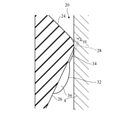
- the sealing device 1 is arranged between the stationary housing (outer member) 2 and the rotating shaft (inner member) 4, and includes the housing 2 and the rotating shaft 4. Seal the gap between.
- a shaft hole 2A is formed in the housing 2, and a rotating shaft 4 is arranged in the shaft hole 2A.
- a liquid, that is, oil, which is a lubricant, is arranged in the internal space of the housing 2.
- the rotating shaft 4 has a columnar shape
- the shaft hole 2A has a circular cross section
- the sealing device 1 has an annular shape, but in FIG. 1, only the left half thereof are shown.
- the rotating shaft 4 is, for example, a drive shaft, a transmission shaft, or an axle of an automobile.
- the sealing device 1 has an outer cylindrical portion 10, a connecting portion 12, and an inner cylindrical portion 14.
- the outer cylindrical portion 10 is a mounting portion attached to the housing 2.
- the outer cylindrical portion 10 is fitted (that is, press-fitted) into the shaft hole 2A by a tightening method.
- the connecting portion 12 is arranged closer to the atmosphere than the outer cylindrical portion 10 and connects the outer cylindrical portion 10 and the inner cylindrical portion 14.
- the sealing device 1 has a composite structure having an elastic ring 16 and a rigid ring 18.
- the elastic ring 16 is made of an elastic material, for example, an elastomer.
- the rigid ring 18 is made of a rigid material, for example metal, to reinforce the elastic ring 16.
- the rigid ring 18 has a substantially L-shaped cross-sectional shape.
- the rigid ring 18 is embedded in the elastic ring 16 and is in close contact with the elastic ring 16. Specifically, the rigid ring 18 is provided over the outer cylindrical portion 10 and the connecting portion 12.
- the inner cylindrical portion 14 is made of only an elastic material, and the inner cylindrical portion 14 is formed with a seal lip 20 and a dust strip 22.
- the seal lip 20 and the dust strip 22 are arranged inside the shaft hole 2A of the housing 2 and slidably contact the outer peripheral surface of the rotating shaft 4.
- the seal lip 20 separates the internal space of the housing 2 from the atmosphere side and seals the liquid in the internal space. That is, the seal lip 20 plays a role of preventing the outflow of the lubricant.
- the dust strip 22 is arranged on the atmospheric side of the seal lip 20 and plays a role of blocking the inflow of foreign substances (including water (including muddy water or salt water) and dust) from the atmospheric side into the internal space.
- the dust strip 22 is an inclined annular plate that extends obliquely from its base toward the atmosphere and radially inward.
- the seal lip 20 is a protrusion formed on the inner peripheral surface of the inner cylindrical portion 14, and is a liquid side inclined surface 24 arranged on the internal space side, an atmospheric side inclined surface 26 arranged on the atmospheric side, and a liquid side. It has a lip edge 28 extending in the circumferential direction at the boundary between the inclined surface 24 and the atmospheric side inclined surface 26.
- the liquid-side inclined surface 24 has the shape of the side surface of the truncated cone, and is inclined so as to be separated from the rotation axis 4 as the distance from the lip edge 28 increases.
- the atmospheric side inclined surface 26 also has the shape of the side surface of the truncated cone, and is inclined so as to be separated from the rotation axis 4 as the distance from the lip edge 28 increases.
- a garter spring 30 that compresses the seal lip 20 inward in the radial direction is wound around the outer peripheral surface of the inner cylindrical portion 14.
- the garter spring 30 is not always indispensable.
- a plurality of spiral ribs 32 are formed on the inclined surface 26 on the atmosphere side. These spiral ribs 32 are inclined with respect to the lip edge 28 and extend spirally. The spiral ribs 32 are arranged at equal intervals in the circumferential direction.
- FIG. 2 is a developed view of the inner peripheral surface of the seal lip 20.
- each spiral rib 32 has a straight portion 34 and a boat bottom shaped portion 36 that extends and curves beyond the side wall 34a of the straight portion 34.
- the straight line portion 34 is a portion referred to as a “parallel screw protrusion” in Patent Document 1, extends linearly, and has side portions 34a parallel to each other.
- the boat bottom shape portion 36 is a portion referred to as a “boat bottom screw protrusion” in Patent Document 1, and has the shape of a boat bottom. That is, the width of the boat bottom shape portion 36 gradually increases from one end along the longitudinal direction of the boat bottom shape portion 36, and gradually decreases from the central portion to the other end.
- the straight line portion 34 and the boat bottom shape portion 36 are arranged in series, the straight line portion 34 extends from the lip edge 28, and the boat bottom shape portion 36 is from the lip edge 28 rather than the straight line portion 34. It is located far away (on the atmosphere side).
- FIG. 3 shows a state in which the seal lip 20 including the spiral rib 32 is in contact with the outer peripheral surface of the rotating shaft 4.
- the lip edge 28 and the spiral rib 32 are elastically deformed in contact with the outer peripheral surface of the rotating shaft 4.
- the amount of deformation of the lip edge 28 is called the tightening allowance IN.
- the straight portion 34 of the spiral rib 32 close to the lip edge 28 has a uniform height with respect to the atmospheric side inclined surface 26 over the longitudinal direction of the spiral rib 32 in a state where it is not elastically deformed (indicated by a virtual line). Has H.
- the portion of the straight portion 34 near the lip edge 28 is elastically deformed in contact with the outer peripheral surface of the rotation shaft 4.
- the amount of deformation (tightening allowance IN) of the lip edge 28 is much larger than the height H of the straight line portion 34, but the height H is exaggerated in FIG.
- the boat bottom shaped portion 36 away from the lip edge 28 does not come into contact with the outer peripheral surface of the rotating shaft 4. However, if the straight portion 34 is worn, the boat bottom shaped portion 36 may come into contact with the outer peripheral surface of the rotation shaft 4.
- the height H of the straight portion 34 means the height of the straight portion 34 in the initial state after the sealing device 1 is manufactured.
- each spiral rib 32 is adapted to the rotation of the rotation axis 4 in the first direction R1 of FIG. That is, when the rotation axis 4 rotates in the first direction (forward direction, that is, the normal rotation direction of the rotation axis 4) R1, each spiral rib 32 exerts a pumping action to return the liquid from the atmosphere side to the internal space. ..
- the applicant conducted an experiment to investigate the performance of the spiral rib 32 by using a sample of a plurality of sealing devices 1 having different heights H of the straight portion 34 of the spiral rib 32.
- the height H was 14 ⁇ m, 25 ⁇ m, 37 ⁇ m, and 48 ⁇ m.
- the material of the elastic ring 16 of the sample was FKM (fluororubber).
- the diameter of the rotating shaft 4 in contact with the seal lip 20 was 65 mm.
- the liquid stored in the internal space is a low-viscosity ATF (Automatic Transmission Fluid).
- ATF Automatic Transmission Fluid
- the liquid was put up to the height of the central axis of the rotating shaft 4 (the part below the central axis of the rotating shaft 4 was immersed in the liquid).
- the rotation axis 4 was rotated in both the first direction R1 and the second direction R2, and it was determined whether or not the liquid leaked to the atmosphere side. Specifically, when the liquid got over the dust strip 22 and was visible, it was determined that the liquid leaked to the atmosphere side.
- the distance from the lip edge 28 of the seal lip 20 to the dust strip 22 was 6 mm under no load.
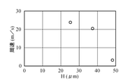
- FIG. 4 the lowest peripheral speed at which the liquid leaks to the atmosphere is plotted for each sample when the rotation axis 4 is rotated in the second direction R2.
- the height H was 48 ⁇ m
- the liquid leaked to the atmosphere even at a significantly low peripheral speed.
- the height H was 25 ⁇ m or 37 ⁇ m
- the liquid leaked to the atmosphere at a peripheral speed higher than 20 m / s. This indicates that when the height H is 25 ⁇ m or 37 ⁇ m, the liquid does not leak to the atmosphere even if the rotating shaft 4 is rotated in the second direction R2 at a peripheral speed of 20 m / s.
- the height H of the straight portion 34 of each spiral rib 32 with respect to the atmospheric side inclined surface 26 is preferably 37 ⁇ m or less. Since the height H of the straight portion 34 of each spiral rib 32 is 37 ⁇ m or less, even if the rotation axis 4 rotates at high speed in the second direction (reverse direction) R2 with respect to the housing 2, the liquid is on the atmosphere side. Can be suppressed from leaking.
- the height H of the straight portion 34 of each spiral rib 32 with respect to the atmospheric side inclined surface 26 is preferably 5 ⁇ m or more. Since the height H of the straight portion 34 of each spiral rib 32 is 5 ⁇ m or more, each spiral rib 32 is pumped when the rotation axis 4 rotates in the first direction (forward direction) R1 with respect to the housing 2. It works.
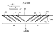
- FIG. 5 is a developed view of the inner peripheral surface of the seal lip 20 of the sealing device according to the modified example of the embodiment.
- a plurality of spiral ribs 32 extending in different directions are provided.
- a plurality of groups 42 in which each group is composed of a plurality of spiral ribs 32 and a plurality of spiral ribs 32 in each group are shown.
- a plurality of groups 44 composed of the group 44 are provided on the atmospheric side inclined surface 26, and the groups 42 and 44 are arranged alternately in the circumferential direction.
- each spiral rib 32 of the group 42 exerts a pumping action to return the liquid from the atmosphere side to the internal space.
- each spiral rib 32 of the group 44 exerts a pumping action to return the liquid from the atmosphere side to the internal space.
- the spiral rib 32 of any group exerts a pumping action regardless of which direction the rotating shaft 4 rotates.
- the present invention is not intended to exclude the modifications of FIG.
- the rotating shaft 4 is, for example, the axle of an automobile
- the rotation direction of the rotating shaft 4 differs depending on whether the axle is arranged on the left or right.
- two types of sealing devices having different inclination directions of the spiral rib 32 are prepared, and it is preferable to select the sealing device according to the rotation direction.
- the sealing device 1 is arranged between the stationary housing (outer member) 2 and the rotating shaft (inner member) 4, but has a rotating outer member and a stationary inner member. It may be placed in between.
- Sealing device Housing (outer member) 4 Rotating shaft (inner member) 10 Outer cylindrical part (mounting part) 12 Connecting part 14 Inner cylindrical part 20 Seal lip 22 Dustrip 24 Liquid side inclined surface 26 Atmospheric side inclined surface 28 Lip edge 32 Spiral rib 34 Straight part 34a Side wall 36 Boat bottom shape part
Landscapes
- Engineering & Computer Science (AREA)
- General Engineering & Computer Science (AREA)
- Mechanical Engineering (AREA)
- Physics & Mathematics (AREA)
- Fluid Mechanics (AREA)
- Sealing With Elastic Sealing Lips (AREA)
Priority Applications (5)
| Application Number | Priority Date | Filing Date | Title |
|---|---|---|---|
| US18/026,286 US12590637B2 (en) | 2020-09-15 | 2021-07-29 | Sealing device |
| JP2022550398A JP7644771B2 (ja) | 2020-09-15 | 2021-07-29 | 密封装置 |
| KR1020237008234A KR20230045090A (ko) | 2020-09-15 | 2021-07-29 | 밀봉 장치 |
| CN202180061873.1A CN116057304A (zh) | 2020-09-15 | 2021-07-29 | 密封装置 |
| EP21869047.7A EP4215779A4 (en) | 2020-09-15 | 2021-07-29 | SEALING DEVICE |
Applications Claiming Priority (2)
| Application Number | Priority Date | Filing Date | Title |
|---|---|---|---|
| JP2020-154931 | 2020-09-15 | ||
| JP2020154931 | 2020-09-15 |
Publications (1)
| Publication Number | Publication Date |
|---|---|
| WO2022059360A1 true WO2022059360A1 (ja) | 2022-03-24 |
Family
ID=80775813
Family Applications (1)
| Application Number | Title | Priority Date | Filing Date |
|---|---|---|---|
| PCT/JP2021/028204 Ceased WO2022059360A1 (ja) | 2020-09-15 | 2021-07-29 | 密封装置 |
Country Status (6)
| Country | Link |
|---|---|
| US (1) | US12590637B2 (https=) |
| EP (1) | EP4215779A4 (https=) |
| JP (1) | JP7644771B2 (https=) |
| KR (1) | KR20230045090A (https=) |
| CN (1) | CN116057304A (https=) |
| WO (1) | WO2022059360A1 (https=) |
Cited By (1)
| Publication number | Priority date | Publication date | Assignee | Title |
|---|---|---|---|---|
| WO2024106416A1 (ja) * | 2022-11-17 | 2024-05-23 | Nok株式会社 | 密封装置 |
Families Citing this family (1)
| Publication number | Priority date | Publication date | Assignee | Title |
|---|---|---|---|---|
| CN119244746B (zh) * | 2024-12-05 | 2025-03-11 | 宁国市四方精工机械股份有限公司 | 一种汽轮机主气门用轴承座油封 |
Citations (6)
| Publication number | Priority date | Publication date | Assignee | Title |
|---|---|---|---|---|
| JPH1019135A (ja) * | 1996-07-02 | 1998-01-23 | Koyo Shikagoroohaido Kk | オイルシール |
| JP2001173798A (ja) * | 1999-12-20 | 2001-06-26 | Arai Pump Mfg Co Ltd | ねじ付オイルシール |
| JP3278349B2 (ja) | 1995-05-25 | 2002-04-30 | エヌオーケー株式会社 | 密封装置 |
| JP2005172061A (ja) * | 2003-12-09 | 2005-06-30 | Nok Corp | 密封装置 |
| WO2015053170A1 (ja) * | 2013-10-10 | 2015-04-16 | Nok株式会社 | 密封装置 |
| WO2020045070A1 (ja) * | 2018-08-28 | 2020-03-05 | Nok株式会社 | 密封装置 |
Family Cites Families (11)
| Publication number | Priority date | Publication date | Assignee | Title |
|---|---|---|---|---|
| JPS5845310Y2 (ja) | 1979-02-26 | 1983-10-14 | 三谷セキサン株式会社 | 分水ブロツク |
| JPS5749949U (https=) * | 1980-09-05 | 1982-03-20 | ||
| JP2558504B2 (ja) | 1988-06-13 | 1996-11-27 | 光洋精工株式会社 | オイルシール |
| US5759466A (en) | 1995-05-25 | 1998-06-02 | Nok Corporation | Method of making lip-type oil seals having improved sealing edge |
| JPH11311338A (ja) | 1998-02-27 | 1999-11-09 | Nok Corp | オイルシ―ル |
| JP4366897B2 (ja) * | 2002-02-28 | 2009-11-18 | Nok株式会社 | 成形型の加工方法 |
| JP5637172B2 (ja) * | 2012-04-27 | 2014-12-10 | Nok株式会社 | 密封装置 |
| JP6177582B2 (ja) * | 2013-05-14 | 2017-08-09 | Nok株式会社 | 密封装置 |
| JP6267475B2 (ja) * | 2013-10-04 | 2018-01-24 | Nok株式会社 | 密封装置 |
| WO2016158211A1 (ja) * | 2015-03-31 | 2016-10-06 | Nok株式会社 | 密封装置 |
| JP6809847B2 (ja) * | 2016-09-01 | 2021-01-06 | Nok株式会社 | 密封装置 |
-
2021
- 2021-07-29 US US18/026,286 patent/US12590637B2/en active Active
- 2021-07-29 EP EP21869047.7A patent/EP4215779A4/en active Pending
- 2021-07-29 WO PCT/JP2021/028204 patent/WO2022059360A1/ja not_active Ceased
- 2021-07-29 JP JP2022550398A patent/JP7644771B2/ja active Active
- 2021-07-29 CN CN202180061873.1A patent/CN116057304A/zh active Pending
- 2021-07-29 KR KR1020237008234A patent/KR20230045090A/ko active Pending
Patent Citations (6)
| Publication number | Priority date | Publication date | Assignee | Title |
|---|---|---|---|---|
| JP3278349B2 (ja) | 1995-05-25 | 2002-04-30 | エヌオーケー株式会社 | 密封装置 |
| JPH1019135A (ja) * | 1996-07-02 | 1998-01-23 | Koyo Shikagoroohaido Kk | オイルシール |
| JP2001173798A (ja) * | 1999-12-20 | 2001-06-26 | Arai Pump Mfg Co Ltd | ねじ付オイルシール |
| JP2005172061A (ja) * | 2003-12-09 | 2005-06-30 | Nok Corp | 密封装置 |
| WO2015053170A1 (ja) * | 2013-10-10 | 2015-04-16 | Nok株式会社 | 密封装置 |
| WO2020045070A1 (ja) * | 2018-08-28 | 2020-03-05 | Nok株式会社 | 密封装置 |
Non-Patent Citations (1)
| Title |
|---|
| See also references of EP4215779A4 |
Cited By (1)
| Publication number | Priority date | Publication date | Assignee | Title |
|---|---|---|---|---|
| WO2024106416A1 (ja) * | 2022-11-17 | 2024-05-23 | Nok株式会社 | 密封装置 |
Also Published As
| Publication number | Publication date |
|---|---|
| US12590637B2 (en) | 2026-03-31 |
| CN116057304A (zh) | 2023-05-02 |
| EP4215779A1 (en) | 2023-07-26 |
| US20240026977A1 (en) | 2024-01-25 |
| KR20230045090A (ko) | 2023-04-04 |
| EP4215779A4 (en) | 2024-10-09 |
| JPWO2022059360A1 (https=) | 2022-03-24 |
| JP7644771B2 (ja) | 2025-03-12 |
Similar Documents
| Publication | Publication Date | Title |
|---|---|---|
| JP6445085B2 (ja) | 密封装置 | |
| JP6961094B2 (ja) | 密封装置 | |
| JP6267475B2 (ja) | 密封装置 | |
| US20100237567A1 (en) | Sealing element | |
| WO2022059360A1 (ja) | 密封装置 | |
| JP2001317635A (ja) | リップ型シール | |
| JP2001317636A (ja) | リップ型シール | |
| JP2011174570A (ja) | 密封装置 | |
| WO2019009053A1 (ja) | 密封装置 | |
| US20050242521A1 (en) | Radial shaft sealing ring | |
| JP7203723B2 (ja) | 密封装置 | |
| JP2018091372A (ja) | 密封装置 | |
| US20140175755A1 (en) | Shaft seal ring with anti-rotation features | |
| JP5092166B2 (ja) | シャフトシール装置 | |
| JP7051310B2 (ja) | 密封装置 | |
| WO2021241481A1 (ja) | 密封装置 | |
| JP2019015352A (ja) | 密封装置 | |
| JP5823290B2 (ja) | 密閉装置を備えたニードル軸受組立体 | |
| JP7161945B2 (ja) | 密封装置 | |
| WO2024106416A1 (ja) | 密封装置 | |
| KR101674424B1 (ko) | 자동차 엔진미션용 저마찰 회전용 샤프트 씰 | |
| JP2020176694A (ja) | 密封装置 | |
| JP2020094617A (ja) | 密封装置 | |
| JP2008286320A (ja) | 密封装置 | |
| JP2008020031A (ja) | オイルシール |
Legal Events
| Date | Code | Title | Description |
|---|---|---|---|
| 121 | Ep: the epo has been informed by wipo that ep was designated in this application |
Ref document number: 21869047 Country of ref document: EP Kind code of ref document: A1 |
|
| ENP | Entry into the national phase |
Ref document number: 20237008234 Country of ref document: KR Kind code of ref document: A |
|
| ENP | Entry into the national phase |
Ref document number: 2022550398 Country of ref document: JP Kind code of ref document: A |
|
| WWE | Wipo information: entry into national phase |
Ref document number: 18026286 Country of ref document: US |
|
| NENP | Non-entry into the national phase |
Ref country code: DE |
|
| ENP | Entry into the national phase |
Ref document number: 2021869047 Country of ref document: EP Effective date: 20230417 |
|
| WWR | Wipo information: refused in national office |
Ref document number: 1020237008234 Country of ref document: KR |
|
| WWC | Wipo information: continuation of processing after refusal or withdrawal |
Ref document number: 1020237008234 Country of ref document: KR |
|
| WWG | Wipo information: grant in national office |
Ref document number: 18026286 Country of ref document: US |