WO2022054219A1 - 固定子、電動機、圧縮機、空気調和機、及び固定子の製造方法 - Google Patents
固定子、電動機、圧縮機、空気調和機、及び固定子の製造方法 Download PDFInfo
- Publication number
- WO2022054219A1 WO2022054219A1 PCT/JP2020/034397 JP2020034397W WO2022054219A1 WO 2022054219 A1 WO2022054219 A1 WO 2022054219A1 JP 2020034397 W JP2020034397 W JP 2020034397W WO 2022054219 A1 WO2022054219 A1 WO 2022054219A1
- Authority
- WO
- WIPO (PCT)
- Prior art keywords
- coil
- phase
- coils
- stator
- stator core
- Prior art date
Links
- 238000004519 manufacturing process Methods 0.000 title claims description 30
- 238000000034 method Methods 0.000 title claims description 24
- 238000004804 winding Methods 0.000 claims abstract description 52
- 230000006835 compression Effects 0.000 claims description 14
- 238000007906 compression Methods 0.000 claims description 14
- 238000009413 insulation Methods 0.000 abstract description 5
- 238000003780 insertion Methods 0.000 description 47
- 230000037431 insertion Effects 0.000 description 47
- 238000010586 diagram Methods 0.000 description 22
- 239000003507 refrigerant Substances 0.000 description 19
- 230000004048 modification Effects 0.000 description 18
- 238000012986 modification Methods 0.000 description 18
- 238000004378 air conditioning Methods 0.000 description 10
- 230000008569 process Effects 0.000 description 10
- 230000008901 benefit Effects 0.000 description 9
- 230000007246 mechanism Effects 0.000 description 7
- 230000000052 comparative effect Effects 0.000 description 4
- 238000001816 cooling Methods 0.000 description 4
- 230000015556 catabolic process Effects 0.000 description 2
- 239000011248 coating agent Substances 0.000 description 2
- 238000000576 coating method Methods 0.000 description 2
- 230000004907 flux Effects 0.000 description 2
- 230000004888 barrier function Effects 0.000 description 1
- 230000006837 decompression Effects 0.000 description 1
- 230000007423 decrease Effects 0.000 description 1
- 238000007599 discharging Methods 0.000 description 1
- 238000009826 distribution Methods 0.000 description 1
- 239000011521 glass Substances 0.000 description 1
- 238000010438 heat treatment Methods 0.000 description 1
- 230000000149 penetrating effect Effects 0.000 description 1
- 238000005057 refrigeration Methods 0.000 description 1
- 230000001360 synchronised effect Effects 0.000 description 1
- 238000003466 welding Methods 0.000 description 1
Images


Classifications
-
- H—ELECTRICITY
- H02—GENERATION; CONVERSION OR DISTRIBUTION OF ELECTRIC POWER
- H02K—DYNAMO-ELECTRIC MACHINES
- H02K3/00—Details of windings
- H02K3/04—Windings characterised by the conductor shape, form or construction, e.g. with bar conductors
- H02K3/28—Layout of windings or of connections between windings
-
- F—MECHANICAL ENGINEERING; LIGHTING; HEATING; WEAPONS; BLASTING
- F24—HEATING; RANGES; VENTILATING
- F24F—AIR-CONDITIONING; AIR-HUMIDIFICATION; VENTILATION; USE OF AIR CURRENTS FOR SCREENING
- F24F1/00—Room units for air-conditioning, e.g. separate or self-contained units or units receiving primary air from a central station
- F24F1/06—Separate outdoor units, e.g. outdoor unit to be linked to a separate room comprising a compressor and a heat exchanger
- F24F1/08—Compressors specially adapted for separate outdoor units
-
- F—MECHANICAL ENGINEERING; LIGHTING; HEATING; WEAPONS; BLASTING
- F25—REFRIGERATION OR COOLING; COMBINED HEATING AND REFRIGERATION SYSTEMS; HEAT PUMP SYSTEMS; MANUFACTURE OR STORAGE OF ICE; LIQUEFACTION SOLIDIFICATION OF GASES
- F25B—REFRIGERATION MACHINES, PLANTS OR SYSTEMS; COMBINED HEATING AND REFRIGERATION SYSTEMS; HEAT PUMP SYSTEMS
- F25B31/00—Compressor arrangements
- F25B31/02—Compressor arrangements of motor-compressor units
- F25B31/026—Compressor arrangements of motor-compressor units with compressor of rotary type
-
- H—ELECTRICITY
- H02—GENERATION; CONVERSION OR DISTRIBUTION OF ELECTRIC POWER
- H02K—DYNAMO-ELECTRIC MACHINES
- H02K15/00—Processes or apparatus specially adapted for manufacturing, assembling, maintaining or repairing of dynamo-electric machines
- H02K15/06—Embedding prefabricated windings in the machines
- H02K15/062—Windings in slots; Salient pole windings
- H02K15/065—Windings consisting of complete sections, e.g. coils or waves
- H02K15/067—Windings consisting of complete sections, e.g. coils or waves inserted in parallel to the axis of the slots or inter-polar channels
- H02K15/068—Strippers; Embedding windings by strippers
-
- H—ELECTRICITY
- H02—GENERATION; CONVERSION OR DISTRIBUTION OF ELECTRIC POWER
- H02K—DYNAMO-ELECTRIC MACHINES
- H02K21/00—Synchronous motors having permanent magnets; Synchronous generators having permanent magnets
- H02K21/12—Synchronous motors having permanent magnets; Synchronous generators having permanent magnets with stationary armatures and rotating magnets
- H02K21/14—Synchronous motors having permanent magnets; Synchronous generators having permanent magnets with stationary armatures and rotating magnets with magnets rotating within the armatures
-
- H—ELECTRICITY
- H02—GENERATION; CONVERSION OR DISTRIBUTION OF ELECTRIC POWER
- H02K—DYNAMO-ELECTRIC MACHINES
- H02K3/00—Details of windings
- H02K3/32—Windings characterised by the shape, form or construction of the insulation
- H02K3/34—Windings characterised by the shape, form or construction of the insulation between conductors or between conductor and core, e.g. slot insulation
- H02K3/345—Windings characterised by the shape, form or construction of the insulation between conductors or between conductor and core, e.g. slot insulation between conductor and core, e.g. slot insulation
-
- H—ELECTRICITY
- H02—GENERATION; CONVERSION OR DISTRIBUTION OF ELECTRIC POWER
- H02K—DYNAMO-ELECTRIC MACHINES
- H02K1/00—Details of the magnetic circuit
- H02K1/06—Details of the magnetic circuit characterised by the shape, form or construction
- H02K1/22—Rotating parts of the magnetic circuit
- H02K1/27—Rotor cores with permanent magnets
- H02K1/2706—Inner rotors
- H02K1/272—Inner rotors the magnetisation axis of the magnets being perpendicular to the rotor axis
- H02K1/274—Inner rotors the magnetisation axis of the magnets being perpendicular to the rotor axis the rotor consisting of two or more circumferentially positioned magnets
- H02K1/2753—Inner rotors the magnetisation axis of the magnets being perpendicular to the rotor axis the rotor consisting of two or more circumferentially positioned magnets the rotor consisting of magnets or groups of magnets arranged with alternating polarity
- H02K1/276—Magnets embedded in the magnetic core, e.g. interior permanent magnets [IPM]
Definitions
- This disclosure relates to a stator for motors.
- a stator having a three-phase coil is known (for example, Patent Document 1).
- the stator core disclosed in Patent Document 1 has 24 slots, the three-phase coil forms eight poles, and the number of slots for one pole is three.
- the coils of each phase are arranged in every three slots, and are attached to the stator core by lap winding, and two coils of the same phase are arranged in each slot.
- this stator has the advantage that 100% of the magnetic flux from the rotor can be used.
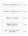
- the purpose of this disclosure is to improve the productivity of stators.
- the stator is A stator core with 9 x n slots (n is an integer of 1 or more) and A three-phase coil, which is attached to the stator core by distributed winding and forms 4 ⁇ n magnetic poles, A first insulating member that insulates the three-phase coil is provided.
- the three-phase coil has 2 ⁇ n U-phase coils, 2 ⁇ n V-phase coils, and 2 ⁇ n W-phase coils at the coil ends of the three-phase coil.
- the 2 ⁇ n U-phase coils are connected in series and The 2 ⁇ n V-phase coils are connected in series and The 2 ⁇ n W-phase coils are connected in series and Each of the 2 ⁇ n U-phase coils, the 2 ⁇ n V-phase coils, and the 2 ⁇ n W-phase coils has nths arranged in the stator core at a 2-slot pitch. It includes one coil and n second coils arranged in the stator core at a 3-slot pitch. The n first coils are arranged at equal intervals at 360 / n degrees in the circumferential direction at the coil end.
- the n second coils are arranged at equal intervals at 360 / n degrees in the circumferential direction at the coil end.
- the n second coils are arranged at the coil end outside the n first coils in the radial direction.
- the first insulating member is arranged in the slot in which the second coil is arranged among the 9 ⁇ n slots.
- Stator according to other aspects of the present disclosure A stator core with 9 x n slots (n is an integer of 1 or more) and A three-phase coil, which is attached to the stator core by distributed winding and forms 4 ⁇ n magnetic poles, A first insulating member that insulates the three-phase coil is provided.
- the three-phase coil has 2 ⁇ n U-phase coils, 2 ⁇ n V-phase coils, and 2 ⁇ n W-phase coils at the coil ends of the three-phase coil.
- the 2 ⁇ n U-phase coils are connected in series and The 2 ⁇ n V-phase coils are connected in series and The 2 ⁇ n W-phase coils are connected in series and
- Each of the 2 ⁇ n U-phase coils, the 2 ⁇ n V-phase coils, and the 2 ⁇ n W-phase coils has nths arranged in the stator core at a 2-slot pitch. It includes one coil and n second coils arranged in the stator core at a 3-slot pitch.
- the n first coils are arranged at equal intervals at 360 / n degrees in the circumferential direction at the coil end.
- the n second coils are arranged at equal intervals at 360 / n degrees in the circumferential direction at the coil end.
- the n first coils are arranged at the coil end outside the n second coils in the radial direction.
- the first insulating member is arranged in the slot in which the second coil is arranged among the 9 ⁇ n slots.
- the motor according to another aspect of the present disclosure is With the stator It includes a rotor arranged inside the stator.
- the compressor according to another aspect of the present disclosure is With a closed container With the compression device arranged in the closed container, The electric motor for driving the compression device is provided.
- the air conditioner according to another aspect of the present disclosure is With the compressor Equipped with a heat exchanger.
- the method for manufacturing a stator according to another aspect of the present disclosure is as follows.
- the 2 ⁇ n U-phase coils, the 2 ⁇ n V-phase coils, and the 2 ⁇ n W-phase coils each have n first coils and n second coils.
- the insulating member is arranged in the slot in which the second coil is arranged so as to insulate the n second coils. It comprises arranging the n first coils inside the n second coils in the radial direction at a two-slot pitch.
- the method for manufacturing a stator according to another aspect of the present disclosure is as follows. A stator core with slots, a 3 phase with 2 x n (n is an integer of 1 or more) U-phase coils, 2 x n V-phase coils, and 2 x n W-phase coils at the coil end. It is a method of manufacturing a stator with a coil.
- the 2 ⁇ n U-phase coils, the 2 ⁇ n V-phase coils, and the 2 ⁇ n W-phase coils each have n first coils and n second coils.
- n first coils on the stator core at a 2-slot pitch
- n second coils inside the n first coils in the radial direction at a pitch of 3 slots
- the insulating member is arranged in the slot in which the second coil is arranged so as to insulate the n second coils.
- the productivity of the stator can be improved.
- FIG. It is a top view which shows schematic structure of the electric motor which concerns on Embodiment 1.
- FIG. It is sectional drawing which shows schematic structure of a rotor. It is a top view which shows the structure of a stator schematically. It is a figure which shows schematically a three-phase coil. It is a figure which shows typically the arrangement of the three-phase coil in a slot. It is a figure which shows the example of the arrangement of the insulating member (also referred to as a 1st insulating member) in a slot. It is a figure which shows the example of the arrangement of the insulating member (also referred to as a 2nd insulating member) in a coil end.
- FIG. 1 It is a flowchart which shows an example of the manufacturing process of the stator in Embodiment 1. It is a figure which shows the example of the insertion instrument for inserting a three-phase coil into a stator core. It is a figure which shows the insertion process of the 2nd coil in step S11. It is a figure which shows the insertion process of the additional 2nd coil in step S13. It is a figure which shows the insertion process of the 1st coil in step S14. It is a top view which shows the electric motor which concerns on a comparative example. It is a figure which shows the arrangement of the three-phase coil in the slot of the stator shown in FIG. It is a top view which shows schematic structure of the electric motor which concerns on the modification of Embodiment 1. FIG.
- FIG. It is a top view which shows schematic structure of the stator of the electric motor which concerns on the modification of Embodiment 1.
- FIG. It is a figure which shows schematic the three-phase coil of the electric motor which concerns on the modification of Embodiment 1.
- FIG. It is a flowchart which shows an example of the manufacturing process of the stator in the modification of Embodiment 1. It is a figure which shows the insertion process of the 2nd coil in step S11a. It is a figure which shows the insertion process of the 1st coil in step S13a.
- FIG. It is a top view which shows schematic structure of the stator of the electric motor which concerns on Embodiment 2.
- FIG. It is a top view which shows schematic structure of the stator of the electric motor which concerns on Embodiment 2.
- FIG. It is a top view which shows schematic structure of the electric motor which concerns on the modification of Embodiment 2. It is a top view which shows schematic structure of the stator of the electric motor which concerns on the modification of Embodiment 2.
- FIG. It is a flowchart which shows an example of the manufacturing process of the stator in the modification of Embodiment 2. It is a figure which shows the insertion process of the 1st coil in step S21a. It is a figure which shows the insertion process of the 2nd coil in a step S22a. It is sectional drawing which shows schematic structure of the compressor which concerns on Embodiment 3.
- FIG. It is a figure which shows schematic the structure of the refrigerating air-conditioning apparatus which concerns on Embodiment 4.
- Embodiment 1 In the xyz Cartesian coordinate system shown in each figure, the z-axis direction (z-axis) indicates a direction parallel to the axis Ax of the electric motor 1, and the x-axis direction (x-axis) is orthogonal to the z-axis direction (z-axis).
- the y-axis direction (y-axis) indicates a direction orthogonal to both the z-axis direction and the x-axis direction.
- the axis Ax is the center of the stator 3 and the center of rotation of the rotor 2.
- the direction parallel to the axis Ax is also referred to as "axial direction of rotor 2" or simply "axial direction”.
- the radial direction is the radial direction of the rotor 2 or the stator 3, and is a direction orthogonal to the axis Ax.
- the xy plane is a plane orthogonal to the axial direction.
- the arrow D1 indicates the circumferential direction about the axis Ax.
- the circumferential direction of the rotor 2 or the stator 3 is also simply referred to as "circumferential direction”.
- FIG. 1 is a top view schematically showing the structure of the motor 1 according to the first embodiment.
- the motor 1 has a rotor 2 having a plurality of magnetic poles, a stator 3, and a shaft 4 fixed to the rotor 2.
- the electric motor 1 is, for example, a permanent magnet synchronous motor.
- the rotor 2 is rotatably arranged inside the stator 3. There is an air gap between the rotor 2 and the stator 3. The rotor 2 rotates about the axis Ax.
- FIG. 2 is a cross-sectional view schematically showing the structure of the rotor 2.
- the rotor 2 has a rotor core 21 and a plurality of permanent magnets 22.
- the rotor core 21 has a plurality of magnet insertion holes 211 and a shaft hole 212 in which the shaft 4 is arranged.
- the rotor core 21 may further have at least one flux barrier portion that is a space communicating with each magnet insertion hole 211.
- the rotor 2 has a plurality of permanent magnets 22.
- Each permanent magnet 22 is arranged in each magnet insertion hole 211.
- One permanent magnet 22 forms one magnetic pole of the rotor 2, that is, an N pole or an S pole. However, two or more permanent magnets 22 may form one magnetic pole of the rotor 2.
- one permanent magnet 22 forming one magnetic pole of the rotor 2 is arranged straight in the xy plane.
- a set of permanent magnets 22 forming one magnetic pole of the rotor 2 may be arranged so as to have a V shape.
- each magnetic pole of the rotor 2 is located at the center of the north pole or the south pole of the rotor 2.
- Each magnetic pole of the rotor 2 (also simply referred to as “each magnetic pole” or “magnetic pole”) means a region serving as an N pole or an S pole of the rotor 2.
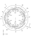
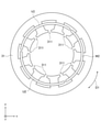
- FIG. 3 is a top view schematically showing the structure of the stator 3.
- FIG. 4 is a diagram schematically showing a three-phase coil 32. As shown in FIGS. 1 and 2, the stator 3 has a stator core 31 and a three-phase coil 32 attached to the stator core 31 in a distributed winding manner.
- the three-phase coil 32 (that is, the coil of each phase) has a coil side arranged in the slot 311 and a coil end 32a not arranged in the slot 311. Each coil end 32a is an end portion of the three-phase coil 32 in the axial direction.
- the three-phase coil 32 has 2 ⁇ n U-phase coils 32U, 2 ⁇ n V-phase coils 32V, and 2 ⁇ n W-phase coils 32W at each coil end 32a (FIG. 1). That is, the three-phase coil 32 has three phases, a first phase, a second phase, and a third phase.
- the first phase is the U phase
- the second phase is the V phase
- the third phase is the W phase.
- each of the three phases is referred to as a U phase, a V phase, and a W phase.
- the 2 ⁇ n U-phase coils 32U are also referred to as “U-phase coil group”
- the 2 ⁇ n V-phase coils 32V are also referred to as “V-phase coil group”
- the 2 ⁇ n W-phase coils 32W are referred to as “W”.
- phase coil group Also referred to as "phase coil group”.
- Each of the U-phase coil group, the V-phase coil group, and the W-phase coil group is also referred to as "a coil group of each phase”.
- the coil group of each phase includes n first coils and n second coils. Each first coil is arranged on the stator core 31 at a 2-slot pitch. Each second coil is arranged on the stator core 31 at a 3-slot pitch. Each first coil of each phase and each second coil of each phase is also simply referred to as a "coil".
- 2 slot pitch means "every 2 slots”. That is, the two-slot pitch means that one coil is arranged in the slot 311 every two slots. In other words, the two-slot pitch means that one coil is arranged in the slot 311 every other slot.
- 3 slot pitch means "every 3 slots". That is, the 3-slot pitch means that one coil is arranged in the slot 311 every 3 slots. In other words, the 3-slot pitch means that one coil is arranged in slot 311 every two slots.
- n 2. Therefore, in the example shown in FIG. 1, at the coil end 32a, the three-phase coil 32 has four U-phase coils 32U, four V-phase coils 32V, and four W-phase coils 32W. However, the number of coils in each phase is not limited to four.
- the stator 3 has the structure shown in FIG. 1 at the two coil ends 32a. However, the stator 3 may have the structure shown in FIG. 1 at one of the two coil ends 32a.
- 2 ⁇ n U-phase coils 32U ie, first coil U1 and second coil U2
- 2 ⁇ n V-phase coils 32V ie, first coil V1
- the second coil V2 and 2 ⁇ n W-phase coils 32W (that is, the first coil W1 and the second coil W2) are connected by, for example, a Y connection.
- the 2 ⁇ n U-phase coils 32U, the 2 ⁇ n V-phase coils 32V, and the 2 ⁇ n W-phase coils 32W are connected by a connection other than the Y connection, for example, a delta connection. good.
- the n first coils of each phase are arranged at equal intervals at 360 / n degrees in the circumferential direction at each coil end 32a.
- the two first coils U1 of the U phase are arranged at equal intervals of 180 degrees in the circumferential direction at each coil end 32a.
- the n first coils U1 are arranged at equal intervals at each coil end 32a with a deviation of 360 / n degrees from each other.
- the two first coils U1 of the U phase are arranged at equal intervals at each coil end 32a with a deviation of 180 degrees from each other.
- n 1
- the first coil of each phase is arranged at an arbitrary position at each coil end 32a.
- the n second coils of each phase are arranged at equal intervals at 360 / n degrees in the circumferential direction at each coil end 32a.
- the two U2 second coils of the U phase are arranged at equal intervals of 180 degrees in the circumferential direction at each coil end 32a.
- the n second coils U2 are arranged at equal intervals at each coil end 32a with a deviation of 360 / n degrees from each other.
- the two second coils U2 of the U phase are arranged at equal intervals at each coil end 32a with a deviation of 180 degrees from each other.
- n 1
- the second coil of each phase is arranged at an arbitrary position at each coil end 32a.
- the two first coils adjacent to each other in the circumferential direction are displaced in the circumferential direction by 240 degrees in the electrical angle (that is, 60 degrees in the mechanical angle).
- the two second coils flanking each other are circumferentially offset by an electrical angle of 240 degrees (ie, a mechanical angle of 60 degrees).
- the region where each coil is arranged in each coil end 32a of the three-phase coil 32 is divided into a plurality of regions, for example, an inner region and an outer region.
- the inner region is the region closest to the center of the stator core 31.
- the outer region is the region farthest from the center of the stator core 31. That is, the outer region is a region located outside the inner region in the xy plane, and the inner region is a region located outside the outer region in the xy plane.
- Each of the inner region and the outer region is a region extending in the circumferential direction.
- each first coil is arranged in the inner region, and each second coil is arranged in the outer region. That is, the first coil is arranged inside the second coil in the radial direction at each coil end 32a. The second coil is located outside the first coil in the radial direction at each coil end 32a.
- the outer region in which the second coil is arranged may be divided into a first outer region and a second outer region.
- the second outer region is a region located outside the inner region in the xy plane
- the first outer region is a region located outside the second outer region in the xy plane. That is, the second outer region is the region between the inner region and the first outer region.
- Each of the first outer region and the second outer region is a region extending in the circumferential direction.
- one second coil of each phase is located in the first outer region and the other second coil of each phase is the second. It is located in the outer area of. Therefore, in each phase, one second coil is radially outerly located as compared to the other second coil.
- the first coil U1 of the U phase, the first coil W1 of the W phase, and the first coil V1 of the V phase are arranged in this order in the circumferential direction (counterclockwise in FIG. 3).
- the U-phase second coil U2, the W-phase second coil W2, and the V-phase second coil V2 are arranged in this order in the circumferential direction (counterclockwise in FIG. 3).
- Each second coil is located in slot 311 along with the second coil of the other phase.
- each coil When viewed in the circumferential direction, each coil is wound around the stator core 31 in the same direction.
- the 2 ⁇ n U-phase coils 32U include n first coils U1 and n second coils U2.
- the two U-phase coils 32U are composed of one first coil U1 and one second coil U2.
- the 2 ⁇ n U-phase coils 32U are connected in series. Therefore, in the present embodiment, the two first coils U1 and the two second coils U2 are connected in series.
- the first coil U1 is arranged on the stator core 31 at a pitch of 2 slots.
- the second coil U2 is arranged on the stator core 31 at a pitch of 3 slots.
- the first coil U1 of the U phase is arranged in two slots 311 every other slot on one end side of the stator core 31.
- the first coil U1 of the U phase is arranged in two slots 311 with one slot 311 interposed therebetween on one end side of the stator core 31.
- the second coil U2 of the U phase is arranged in two slots 311 every two slots on one end side of the stator core 31.
- the second coil U2 of the U phase is arranged in two slots 311 with the two slots 311 interposed therebetween on one end side of the stator core 31.
- Each first coil U1 is arranged inside each coil end 32a inside a second coil of another phase in the radial direction.
- Each second coil U2 is located outside the first coil of the other phase in the radial direction at each coil end 32a.
- the 2 ⁇ n V-phase coils 32V include n first coils V1 and n second coils V2.
- the two V-phase coils 32V are composed of one first coil V1 and one second coil V2.
- the 2 ⁇ n V-phase coils 32V are connected in series. Therefore, in the present embodiment, the two first coils V1 and the two second coils V2 are connected in series.
- the first coil V1 is arranged on the stator core 31 at a 2-slot pitch.
- the second coil V2 is arranged on the stator core 31 at a pitch of 3 slots.
- the first coil V1 of the V phase is arranged in two slots 311 every other slot on one end side of the stator core 31.
- the first coil V1 of the V phase is arranged in two slots 311 with one slot 311 interposed therebetween on one end side of the stator core 31.
- the second coil V2 of the V phase is arranged in two slots 311 every two slots on one end side of the stator core 31.
- the second coil V2 of the V phase is arranged in two slots 311 with the two slots 311 interposed therebetween on one end side of the stator core 31.
- Each first coil V1 is arranged inside each coil end 32a inside a second coil of another phase in the radial direction.
- Each second coil V2 is located outside the first coil of the other phase in the radial direction at each coil end 32a.
- the 2 ⁇ n W-phase coils 32W include n first coils W1 and n second coils W2.
- the two W-phase coils 32W are composed of one first coil W1 and one second coil W2.
- the 2 ⁇ n W-phase coils 32W are connected in series. Therefore, in the present embodiment, the two first coils W1 and the two second coils W2 are connected in series.
- the first coil W1 is arranged on the stator core 31 at a pitch of 2 slots.
- the second coil W2 is arranged on the stator core 31 at a pitch of 3 slots.
- the first coil W1 of the W phase is arranged in two slots 311 every other slot on one end side of the stator core 31.
- the first coil W1 of the W phase is arranged in two slots 311 with one slot 311 interposed therebetween on one end side of the stator core 31.
- the second coil W2 of the W phase is arranged in two slots 311 every two slots on one end side of the stator core 31.
- the second coil W2 of the W phase is arranged in two slots 311 with the two slots 311 interposed therebetween on one end side of the stator core 31.
- Each first coil W1 is arranged inside each coil end 32a inside a second coil of another phase in the radial direction.
- Each second coil W2 is located outside the first coil of the other phase in the radial direction at each coil end 32a.
- FIG. 5 is a diagram schematically showing the arrangement of the three-phase coil 32 in the slot 311.
- the region of that slot 311 is divided into two regions.
- the area of slot 311 is divided into an inner layer and an outer layer located outside the inner layer.
- FIG. 6 is a diagram showing an example of arrangement of the insulating member 34 (also referred to as a first insulating member) in the slot 311.
- the stator 3 may have an insulating member 34 that insulates the coils of each phase of the three-phase coil 32.
- the insulating member 34 is, for example, insulating paper.
- the insulating member 34 is arranged in the slot 311 in which the second coil is arranged out of the 9 ⁇ n slots 311. Specifically, each insulating member 34 is arranged between two second coils in slot 311.
- FIG. 7 is a diagram showing an example of arrangement of the insulating member 34 (also referred to as a second insulating member) in the coil end 32a.
- the stator 3 may have an insulating member 34 that insulates the coils of each phase of the three-phase coil 32 at the coil end 32a.
- the insulating member 34 is, for example, insulating paper. In the example shown in FIG. 7, the insulating member 34 is arranged between the first coil and the second coil at the coil end 32a.
- Winding coefficient kW1 of the first coil of each phase and the winding coefficient kW2 of the second coil of each phase are different from each other. Therefore, in order to calculate the winding coefficient kW of the stator 3 of the motor 1, the winding coefficient kW1 of the first coil of each phase and the winding coefficient kW2 of the second coil of each phase are calculated.
- the short-section winding coefficient Kp1 of the first coil of each phase and the short-section winding coefficient Kp2 of the second coil of each phase are given by the following equations (1), (2), (3), and (4). Is sought after.
- the distribution winding coefficient kd of the stator 3 of the motor 1 is 1. Therefore, the winding coefficient kW of the stator 3 of the motor 1 is obtained by the following equation (5).
- FIG. 8 is a flowchart showing an example of the manufacturing process of the stator 3 in the first embodiment.
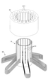
- FIG. 9 is a diagram showing an example of an insertion device 9 for inserting the three-phase coil 32 into the stator core 31.
- FIG. 10 is a diagram showing an insertion step of the second coil in step S11.
- the second coil of each phase is attached to the stator core 31 prepared in advance by the insertion tool 9.
- one second coil of each phase is arranged at equal intervals (specifically, 120 degrees) in the circumferential direction, and each phase is placed on the outer layer of the slot 311 of the stator core 31.
- One second coil of is arranged in a distributed winding. That is, one second coil U2 of the U-phase coil 32U, one second coil V2 of the V-phase coil 32V, and one second coil W2 of the W-phase coil 32W are distributed and wound around the outer layer of the slot 311. Place in.
- one second coil of each phase is arranged in the outer region of the coil end 32a (specifically, the first outer region) and is arranged in the stator core 31 at a 3-slot pitch.
- the coil is arranged between the blades 91 of the insertion tool 9, and the blade 91 is inserted inside the stator core 31 together with the coil. .. Next, the coil is slid axially and placed in slot 311. In the step described later, the three-phase coil 32 is inserted into the stator core 31 by the same method.
- step S12 the insulating member 34 is arranged in the slot 311 in which the second coil of each phase is arranged so as to insulate the second coil of each phase. Specifically, in the next step, the insulating member 34 is arranged in the slot 311 in which the second coil of a different phase is arranged.
- FIG. 11 is a diagram showing an additional second coil insertion step in step S13.
- step S13 as shown in FIG. 11, another second coil of each phase is attached to the stator core 31 by the insertion tool 9. Specifically, at the coil end 32a, another second coil of each phase is arranged at equal intervals in the circumferential direction, and the second coil of each phase is placed in the inner layer of the slot 311 in which the second coil is already arranged. Are arranged in a distributed winding. That is, the other second coil of each phase is arranged in the outer region (specifically, the second outer region) of the coil end 32a.
- the second coil of each phase is arranged in the outer region of the coil end 32a and is arranged in the stator core 31 at a 3-slot pitch.
- the second coil of each phase is the second coil of each phase, the second coil of the U phase U2, the second coil W2 of the W phase, and the second coil of the V phase at each coil end 32a.
- the V2s are arranged in this order in the circumferential direction (counterclockwise in FIG. 11). Each second coil is placed in slot 311 along with the second coil of the other phase.
- FIG. 12 is a diagram showing an insertion step of the first coil in step S14.
- the first coil of each phase is attached to the stator core 31 by the insertion tool 9.
- the first coils of each phase are arranged at equal intervals in the circumferential direction, and the first coils of each phase are arranged in the slot 311 by distributed winding. That is, the first coil U1 of the U-phase coil 32U, the first coil V1 of the V-phase coil 32V, and the first coil W1 of the W-phase coil 32W are arranged in the slot 311 by distributed winding.
- the first coil of each phase is arranged in the inner region of the coil end 32a and is arranged inside the second coil in the radial direction at a 2-slot pitch.
- each first coil is distributed around the stator core 31 at a 2-slot pitch
- each second coil is distributed around the stator core 31 at a 3-slot pitch.
- the three-phase coil 32 is attached to the stator core 31 in a distributed winding manner so that the three-phase coil 32 has the arrangement described in this embodiment at each coil end 32a and slot 311 of the three-phase coil 32. ..
- step S15 the U-phase coil 32U, the V-phase coil 32V, and the W-phase coil 32W are connected to each other.
- the coils of each phase are connected in series. That is, the 2 ⁇ n U-phase coils 32U are connected in series, the 2 ⁇ n V-phase coils 32V are connected in series, and the 2 ⁇ n W-phase coils 32W are connected in series.
- the U-phase coil 32U, the V-phase coil 32V, and the W-phase coil 32W are connected by, for example, a Y connection. Further, the shape of the connected three-phase coil 32 is adjusted. As a result, the stator 3 shown in FIG. 3 is obtained.
- FIG. 13 is a top view showing the electric motor 1a according to the comparative example.
- FIG. 14 is a diagram showing the arrangement of the three-phase coil 32 in the slot of the stator 3a shown in FIG.
- FIG. 14 is a developed view of the stator 3a shown in FIG.
- the three-phase coil 32 is lap-wound and attached to the stator core 31.
- one side of each coil is arranged in the outer layer of slot 311 and the other side of the coil is arranged in the inner layer of the other slot 311.
- the three-phase coil 32 is lap-wound and attached to the stator core 31, it is difficult to attach the three-phase coil 32 to the stator core 31 using an insertion tool (for example, the insertion tool 9 shown in FIG. 9). .. Therefore, usually, when the three-phase coil 32 is attached to the stator core 31 by lap winding as in the comparative example, the three-phase coil 32 is attached to the stator core 31 by hand. In this case, the productivity of the stator 3 decreases.
- an insertion tool for example, the insertion tool 9 shown in FIG. 9
- the three-phase coil 32 can be easily attached to the stator core 31 by using an insertion device (for example, the insertion device 9 shown in FIG. 9). can. Therefore, the productivity of the stator 3 can be improved. Further, in the present embodiment, since the stator 3 has the above-mentioned arrangement, the insulating member 34 can be easily arranged in the slot 311, and the productivity of the stator 3 can be further improved.
- the stator 3 having the advantages described in the present embodiment can be manufactured. Further, according to the method for manufacturing the stator 3, the three-phase coil 32 can be attached to the stator core 31 by using the insertion tool 9. Further, since the second coil is first arranged in the outer region, the first coil can be easily arranged on the stator core 31 and the height of the coil end 32a in the axial direction can be suppressed.
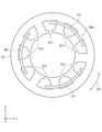
- FIG. 15 is a top view schematically showing the structure of the electric motor 1 according to the modified example of the first embodiment.
- the value of "n" is different from the value of "n” described in the first embodiment.
- n 1.
- a configuration different from that of the first embodiment will be described. The details not explained in the modified example can be the same details as those in the first embodiment.
- the rotor 2 has a rotor core 21 and at least one permanent magnet 22.
- the rotor 2 has 4 ⁇ n (n is an integer of 1 or more) magnetic poles. In the modified example, the rotor 2 has four magnetic poles.
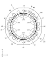
- FIG. 16 is a top view schematically showing the structure of the stator 3 of the electric motor 1 according to the modified example of the first embodiment.
- FIG. 17 is a diagram schematically showing a three-phase coil 32 of the electric motor 1 according to the modified example of the first embodiment.
- the three-phase coil 32 has two U-phase coils 32U, two V-phase coils 32V, and two W-phase coils 32W.
- the coil group of each phase includes one first coil and one second coil.
- Each first coil is arranged on the stator core 31 at a 2-slot pitch.
- Each second coil is arranged on the stator core 31 at a 3-slot pitch.
- 2 ⁇ n U-phase coils 32U ie, one first coil U1 and one second coil U2
- 2 ⁇ n V-phase coils 32V ie, 1). 1, 1st coil V1 and 1st 2nd coil V2)
- 2 ⁇ n W-phase coils 32W ie, 1st coil W1 and 1st 2nd coil W2.
- a connection other than the Y connection for example, a delta connection. good.
- the 2 ⁇ n U-phase coils 32U include n first coils U1 and n second coils U2.
- the four U-phase coils 32U are composed of two first coils U1 and two second coils U2.
- the 2 ⁇ n U-phase coils 32U are connected in series. Therefore, in the modified example, one first coil U1 and one second coil U2 are connected in series.
- the first coil U1 is arranged on the stator core 31 at a pitch of 2 slots.
- the second coil U2 is arranged on the stator core 31 at a pitch of 3 slots.
- the 2 ⁇ n V-phase coils 32V include n first coils V1 and n second coils V2.
- the four V-phase coils 32V are composed of two first coils V1 and two second coils V2.
- the 2 ⁇ n V-phase coils 32V are connected in series. Therefore, in the modified example, one first coil V1 and one second coil V2 are connected in series.
- the first coil V1 is arranged on the stator core 31 at a 2-slot pitch.
- the second coil V2 is arranged on the stator core 31 at a pitch of 3 slots.
- the 2 ⁇ n W-phase coils 32W include n first coils W1 and n second coils W2.
- the four W-phase coils 32W are composed of two first coils W1 and two second coils W2.
- the 2 ⁇ n W-phase coils 32W are connected in series. Therefore, in the modified example, one first coil W1 and one second coil W2 are connected in series.
- the first coil W1 is arranged on the stator core 31 at a pitch of 2 slots.
- the second coil W2 is arranged on the stator core 31 at a pitch of 3 slots.
- Winding coefficient described in the first embodiment can be applied to the stator 3 of the motor 1 according to the modified example.
- FIG. 18 is a flowchart showing an example of the manufacturing process of the stator 3 in the modified example of the first embodiment.
- FIG. 19 is a diagram showing an insertion step of the second coil in step S11a.
- step S11a as shown in FIG. 18, the second coil of each phase is attached to the stator core 31 prepared in advance by the insertion tool 9. Specifically, at the coil end 32a, the second coils of each phase are arranged at equal intervals (specifically, 120 degrees) in the circumferential direction, and the second coil of each phase is placed on the outer layer of the slot 311 of the stator core 31. 2 coils are arranged in a distributed winding.
- the second coil U2 of the U-phase coil 32U, the second coil V2 of the V-phase coil 32V, and the second coil W2 of the W-phase coil 32W are arranged in the outer layer of the slot 311 by distributed winding.
- the second coil of each phase is arranged in the outer region of the coil end 32a and is arranged in the stator core 31 at a 3-slot pitch.
- step S12a the insulating member 34 is arranged in the slot 311 in which the second coil of each phase is arranged so as to insulate the second coil of each phase. Specifically, the insulating member 34 is arranged in the slot 311 in which the second coil of a different phase is arranged.
- FIG. 20 is a diagram showing an insertion step of the first coil in step S13a.
- the first coil of each phase is attached to the stator core 31 by the insertion tool 9.
- the first coils of each phase are arranged at equal intervals in the circumferential direction, and the first coils of each phase are arranged in the slot 311 by distributed winding. That is, the first coil U1 of the U-phase coil 32U, the first coil V1 of the V-phase coil 32V, and the first coil W1 of the W-phase coil 32W are arranged in the slot 311 by distributed winding.
- the first coil of each phase is arranged in the inner region of the coil end 32a and is arranged inside the second coil in the radial direction at a 2-slot pitch.
- each first coil is distributed around the stator core 31 at a 2-slot pitch
- each second coil is distributed around the stator core 31 at a 3-slot pitch.
- Arranged in a distributed winding As a result, the three-phase coil 32 is distributed winding and the stator core 31 so that the three-phase coil 32 has the arrangement described in the modification of the present embodiment in each coil end 32a and the slot 311 of the three-phase coil 32. Attached to.
- step S14a the U-phase coil 32U, the V-phase coil 32V, and the W-phase coil 32W are connected to each other.
- the coils of each phase are connected in series. That is, the 2 ⁇ n U-phase coils 32U are connected in series, the 2 ⁇ n V-phase coils 32V are connected in series, and the 2 ⁇ n W-phase coils 32W are connected in series.
- the U-phase coil 32U, the V-phase coil 32V, and the W-phase coil 32W are connected by, for example, a Y connection. Further, the shape of the connected three-phase coil 32 is adjusted. As a result, the stator 3 shown in FIG. 16 is obtained.
- the stator 3 in the modified example of the first embodiment has the advantages described in the first embodiment. Therefore, the electric motor 1 according to the modification of the first embodiment has the advantages described in the first embodiment.
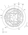
- FIG. 21 is a plan view schematically showing the structure of the electric motor 1 according to the second embodiment.
- the arrangement of the three-phase coil 32 is different from the arrangement described in the first embodiment.
- a configuration different from that of the first embodiment will be described. The details not described in the present embodiment can be the same as those in the first embodiment.
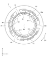
- FIG. 22 is a top view schematically showing the structure of the stator 3 of the motor 1 according to the second embodiment. As shown in FIGS. 21 and 22, the stator 3 has a stator core 31 and a three-phase coil 32 attached to the stator core 31 in a distributed winding manner.
- the three-phase coil 32 has 2 ⁇ n U-phase coils 32U, 2 ⁇ n V-phase coils 32V, and 2 ⁇ n W-phase coils 32W at each coil end 32a (FIG. 21).
- the coil group of each phase includes n first coils and n second coils.
- Each first coil is arranged on the stator core 31 at a 2-slot pitch.
- Each second coil is arranged on the stator core 31 at a 3-slot pitch.
- n 2. Therefore, in the example shown in FIG. 21, at the coil end 32a, the three-phase coil 32 has four U-phase coils 32U, four V-phase coils 32V, and four W-phase coils 32W. However, the number of coils in each phase is not limited to four.
- the stator 3 has the structure shown in FIG. 21 at the two coil ends 32a. However, the stator 3 may have the structure shown in FIG. 21 at one of the two coil ends 32a.
- 2 ⁇ n U-phase coils 32U ie, first coil U1 and second coil U2
- 2 ⁇ n V-phase coils 32V ie, first coil V1 and second coil V2
- 2 ⁇ n W-phase coils 32W that is, the first coil W1 and the second coil W2 are connected by, for example, a Y connection.
- the 2 ⁇ n U-phase coils 32U, the 2 ⁇ n V-phase coils 32V, and the 2 ⁇ n W-phase coils 32W are connected by a connection other than the Y connection, for example, a delta connection. good.
- first coils of each phase are arranged at equal intervals at 360 / n degrees in the circumferential direction at each coil end 32a.
- n second coils of each phase are arranged at equal intervals at 360 / n degrees in the circumferential direction at each coil end 32a.
- n 1
- the second coil of each phase is arranged at an arbitrary position at each coil end 32a.
- the two first coils adjacent to each other in the circumferential direction are displaced in the circumferential direction by 240 degrees in the electrical angle (that is, 60 degrees in the mechanical angle).
- the two second coils flanking each other are circumferentially offset by an electrical angle of 240 degrees (ie, a mechanical angle of 60 degrees).
- each first coil is arranged in the outer region, and each second coil is arranged in the inner region. That is, the first coil is arranged outside the second coil in the radial direction at each coil end 32a. The second coil is arranged inside the first coil in the radial direction at each coil end 32a.
- the inner region in which the second coil is arranged may be divided into a first inner region and a second inner region.
- the first inner region is a region located inside the outer region in the xy plane
- the second inner region is a region located inside the first inner region in the xy plane. That is, the first inner region is the region between the outer region and the second inner region.
- Each of the first inner region and the second inner region is a region extending in the circumferential direction.
- one second coil of each phase is located in the first inner region and the other second coil of each phase is the second. It is located in the inner area of. Therefore, in each phase, one second coil is radially outerly located as compared to the other second coil.
- the first coil U1 of the U phase, the first coil W1 of the W phase, and the first coil V1 of the V phase are arranged in this order in the circumferential direction (counterclockwise in FIG. 22).
- the U-phase second coil U2, the W-phase second coil W2, and the V-phase second coil V2 are arranged in this order in the circumferential direction (counterclockwise in FIG. 3).
- Each second coil is located in slot 311 along with the second coil of the other phase.
- each coil When viewed in the circumferential direction, each coil is wound around the stator core 31 in the same direction.
- the 2 ⁇ n U-phase coils 32U include n first coils U1 and n second coils U2.
- the two U-phase coils 32U are composed of one first coil U1 and one second coil U2.
- the 2 ⁇ n U-phase coils 32U are connected in series. Therefore, in the present embodiment, the two first coils U1 and the two second coils U2 are connected in series.
- the first coil U1 is arranged on the stator core 31 at a pitch of 2 slots.
- the second coil U2 is arranged on the stator core 31 at a pitch of 3 slots.
- the first coil U1 of the U phase is arranged in two slots 311 every other slot on one end side of the stator core 31.
- the first coil U1 of the U phase is arranged in two slots 311 with one slot 311 interposed therebetween on one end side of the stator core 31.
- the second coil U2 of the U phase is arranged in two slots 311 every two slots on one end side of the stator core 31.
- the second coil U2 of the U phase is arranged in two slots 311 with the two slots 311 interposed therebetween on one end side of the stator core 31.
- Each first coil U1 is arranged at each coil end 32a outside the second coil of the other phase in the radial direction.
- Each second coil U2 is located inside each coil end 32a inside the first coil of the other phase in the radial direction.
- the 2 ⁇ n V-phase coils 32V include n first coils V1 and n second coils V2.
- the two V-phase coils 32V are composed of one first coil V1 and one second coil V2.
- the 2 ⁇ n V-phase coils 32V are connected in series. Therefore, in the present embodiment, the two first coils V1 and the two second coils V2 are connected in series.
- the first coil V1 is arranged on the stator core 31 at a 2-slot pitch.
- the second coil V2 is arranged on the stator core 31 at a pitch of 3 slots.
- the first coil V1 of the V phase is arranged in two slots 311 every other slot on one end side of the stator core 31.
- the first coil V1 of the V phase is arranged in two slots 311 with one slot 311 interposed therebetween on one end side of the stator core 31.
- the second coil V2 of the V phase is arranged in two slots 311 every two slots on one end side of the stator core 31.
- the second coil V2 of the V phase is arranged in two slots 311 with the two slots 311 interposed therebetween on one end side of the stator core 31.
- Each first coil V1 is arranged at each coil end 32a outside the second coil of the other phase in the radial direction.
- Each second coil V2 is located inside each coil end 32a inside the first coil of the other phase in the radial direction.
- the 2 ⁇ n W-phase coils 32W include n first coils W1 and n second coils W2.
- the two W-phase coils 32W are composed of one first coil W1 and one second coil W2.
- the 2 ⁇ n W-phase coils 32W are connected in series. Therefore, in the present embodiment, the two first coils W1 and the two second coils W2 are connected in series.
- the first coil W1 is arranged on the stator core 31 at a pitch of 2 slots.
- the second coil W2 is arranged on the stator core 31 at a pitch of 3 slots.
- the first coil W1 of the W phase is arranged in two slots 311 every other slot on one end side of the stator core 31.
- the first coil W1 of the W phase is arranged in two slots 311 with one slot 311 interposed therebetween on one end side of the stator core 31.
- the second coil W2 of the W phase is arranged in two slots 311 every two slots on one end side of the stator core 31.
- the second coil W2 of the W phase is arranged in two slots 311 with the two slots 311 interposed therebetween on one end side of the stator core 31.
- Each first coil W1 is arranged at each coil end 32a outside the second coil of the other phase in the radial direction.
- Each second coil W2 is located inside each coil end 32a inside the first coil of the other phase in the radial direction.
- FIG. 23 is a diagram showing an example of arrangement of the insulating member 34 (also referred to as a first insulating member) in the slot 311.
- the stator 3 may have an insulating member 34 that insulates the coils of each phase of the three-phase coil 32.
- the insulating member 34 is, for example, insulating paper.
- the insulating member 34 is arranged in the slot 311 in which the second coil is arranged out of the 9 ⁇ n slots 311. Specifically, each insulating member 34 is arranged between two second coils in slot 311.
- FIG. 24 is a diagram showing an example of arrangement of the insulating member 34 (also referred to as a second insulating member) in the coil end 32a.
- the stator 3 may have an insulating member 34 that insulates the coils of each phase of the three-phase coil 32 at the coil end 32a.
- the insulating member 34 is, for example, insulating paper. In the example shown in FIG. 24, the insulating member 34 is arranged between the first coil and the second coil at the coil end 32a.
- Winding coefficient described in the first embodiment is applicable to the second embodiment.
- FIG. 25 is a flowchart showing an example of the manufacturing process of the stator 3 in the second embodiment.
- FIG. 26 is a diagram showing an insertion step of the first coil in step S21.
- the first coil of each phase is attached to the stator core 31 by the insertion tool 9.
- the first coils of each phase are arranged at equal intervals in the circumferential direction, and the first coils of each phase are arranged in the slot 311 by distributed winding. That is, the first coil U1 of the U-phase coil 32U, the first coil V1 of the V-phase coil 32V, and the first coil W1 of the W-phase coil 32W are arranged in the slot 311 by distributed winding.
- the first coil of each phase is arranged in the outer region of the coil end 32a and is arranged in the stator core 31 at a 2-slot pitch.
- FIG. 27 is a diagram showing an insertion step of the second coil in step S22.
- the second coil of each phase is attached to the stator core 31 prepared in advance by the insertion tool 9. Specifically, at the coil end 32a, one second coil of each phase is arranged at equal intervals (specifically, 120 degrees) in the circumferential direction, and each phase is placed on the outer layer of the slot 311 of the stator core 31.
- One second coil of is arranged in a distributed winding. That is, one second coil U2 of the U-phase coil 32U, one second coil V2 of the V-phase coil 32V, and one second coil W2 of the W-phase coil 32W are distributed and wound around the outer layer of the slot 311. Place in.
- one second coil of each phase is arranged in the inner region of the coil end 32a (specifically, the first inner region). That is, the first coil is arranged outside the second coil in the radial direction at each coil end 32a, and the second coil is the first coil in the radial direction at each coil end 32a at a pitch of 3 slots. Placed inside.
- step S23 the insulating member 34 is arranged in the slot 311 in which the second coil of each phase is arranged so as to insulate the second coil of each phase. Specifically, in the next step, the insulating member 34 is arranged in the slot 311 in which the second coil of a different phase is arranged.
- FIG. 28 is a diagram showing an additional second coil insertion step in step S24.
- step S24 as shown in FIG. 28, another second coil of each phase is attached to the stator core 31 by the insertion tool 9. Specifically, at the coil end 32a, another second coil of each phase is arranged at equal intervals in the circumferential direction, and the second coil of each phase is placed in the inner layer of the slot 311 in which the second coil is already arranged. Are arranged in a distributed winding. That is, the other second coil of each phase is arranged in the inner region (specifically, the second inner region) of the coil end 32a.
- the second coil of each phase is arranged in the inner region of the coil end 32a and is arranged inside the first coil in the radial direction at a 3-slot pitch.
- the second coil of each phase has the second coil U2 of the U phase, the second coil W2 of the W phase, and the second coil V2 of the V phase in the circumferential direction (in FIG. 28). , Counterclockwise) are arranged in this order.
- Each second coil is placed in slot 311 along with the second coil of the other phase.
- the second coil is disposed inside the first coil in the radial direction at each coil end 32a.
- each first coil is distributed around the stator core 31 at a 2-slot pitch
- each second coil is distributed around the stator core 31 at a 3-slot pitch.
- the three-phase coil 32 is attached to the stator core 31 in a distributed winding manner so that the three-phase coil 32 has the arrangement described in this embodiment at each coil end 32a and slot 311 of the three-phase coil 32. ..
- step S25 the U-phase coil 32U, the V-phase coil 32V, and the W-phase coil 32W are connected to each other.
- the coils of each phase are connected in series. That is, the 2 ⁇ n U-phase coils 32U are connected in series, the 2 ⁇ n V-phase coils 32V are connected in series, and the 2 ⁇ n W-phase coils 32W are connected in series.
- the U-phase coil 32U, the V-phase coil 32V, and the W-phase coil 32W are connected by, for example, a Y connection. Further, the shape of the connected three-phase coil 32 is adjusted. As a result, the stator 3 shown in FIG. 22 is obtained.
- the three-phase coil 32 can be easily attached to the stator core 31 by using an insertion device (for example, the insertion device 9 shown in FIG. 9). can. Therefore, the productivity of the stator 3 can be improved. Further, in the present embodiment, since the stator 3 has the above-mentioned arrangement, the insulating member 34 can be easily arranged in the slot 311, and the productivity of the stator 3 can be further improved.
- the stator 3 having the advantages described in the present embodiment can be manufactured. Further, according to the method for manufacturing the stator 3, the three-phase coil 32 can be attached to the stator core 31 by using the insertion tool 9.
- each second coil is smaller than the diameter of each first coil. In this case, it is easy to adjust the shape of each second coil. Therefore, first, the first coil, which is thicker than the second coil, is placed in the outer region, so that after the first coil is placed in the outer region, the second coil can be easily attached to the stator core 31. Can be placed.
- FIG. 29 is a top view schematically showing the structure of the electric motor 1 according to the modified example of the second embodiment.
- the value of "n" is different from the value of "n” described in the second embodiment.
- n 1.
- a configuration different from that of the second embodiment will be described. The details not explained in the modified example of the second embodiment can be the same details as those of the second embodiment.
- the rotor 2 has a rotor core 21 and at least one permanent magnet 22.
- the rotor 2 has 4 ⁇ n (n is an integer of 1 or more) magnetic poles. In the modified example, the rotor 2 has four magnetic poles.
- FIG. 30 is a top view schematically showing the structure of the stator 3 of the electric motor 1 according to the modified example of the second embodiment.
- the three-phase coil 32 has two U-phase coils 32U, two V-phase coils 32V, and two W-phase coils 32W.
- the coil group of each phase includes one first coil and one second coil.
- Each first coil is arranged on the stator core 31 at a 2-slot pitch.
- Each second coil is arranged on the stator core 31 at a 3-slot pitch.
- 2 ⁇ n U-phase coils 32U ie, one first coil U1 and one second coil U2
- 2 ⁇ n V-phase coils 32V ie, 1). 1, 1st coil V1 and 1st 2nd coil V2)
- 2 ⁇ n W-phase coils 32W ie, 1st coil W1 and 1st 2nd coil W2.
- a connection other than the Y connection for example, a delta connection. good.
- the 2 ⁇ n U-phase coils 32U include n first coils U1 and n second coils U2.
- the four U-phase coils 32U are composed of two first coils U1 and two second coils U2.
- the 2 ⁇ n U-phase coils 32U are connected in series. Therefore, in the modified example, one first coil U1 and one second coil U2 are connected in series.
- the first coil U1 is arranged on the stator core 31 at a pitch of 2 slots.
- the second coil U2 is arranged on the stator core 31 at a pitch of 3 slots.
- the 2 ⁇ n V-phase coils 32V include n first coils V1 and n second coils V2.
- the four V-phase coils 32V are composed of two first coils V1 and two second coils V2.
- the 2 ⁇ n V-phase coils 32V are connected in series. Therefore, in the modified example, one first coil V1 and one second coil V2 are connected in series.
- the first coil V1 is arranged on the stator core 31 at a 2-slot pitch.
- the second coil V2 is arranged on the stator core 31 at a pitch of 3 slots.
- the 2 ⁇ n W-phase coils 32W include n first coils W1 and n second coils W2.
- the four W-phase coils 32W are composed of two first coils W1 and two second coils W2.
- the 2 ⁇ n W-phase coils 32W are connected in series. Therefore, in the modified example, one first coil W1 and one second coil W2 are connected in series.
- the first coil W1 is arranged on the stator core 31 at a pitch of 2 slots.
- the second coil W2 is arranged on the stator core 31 at a pitch of 3 slots.
- Winding coefficient described in the first embodiment can be applied to the stator 3 of the electric motor 1 according to the modification of the second embodiment.
- FIG. 31 is a flowchart showing an example of the manufacturing process of the stator 3 in the modified example of the second embodiment.
- FIG. 32 is a diagram showing an insertion step of the first coil in step S21a.
- the first coil of each phase is attached to the stator core 31 prepared in advance by the insertion tool 9.
- one first coil of each phase is arranged at equal intervals in the circumferential direction, and one first coil of each phase is arranged in the slot 311 by distributed winding. That is, one first coil U1 of the U-phase coil 32U, one first coil V1 of the V-phase coil 32V, and one first coil W1 of the W-phase coil 32W are arranged in the slot 311 by distributed winding. do.
- the first coil of each phase is arranged in the outer region of the coil end 32a and is arranged in the stator core 31 at a 2-slot pitch.
- FIG. 33 is a diagram showing an insertion step of the second coil in step S22a.
- the second coil of each phase is attached to the stator core 31 prepared in advance by the insertion tool 9. Specifically, at the coil end 32a, the second coils of each phase are arranged at equal intervals (specifically, 120 degrees) in the circumferential direction, and the second coil of each phase is placed on the outer layer of the slot 311 of the stator core 31. 2 coils are arranged in a distributed winding.
- the second coil U2 of the U-phase coil 32U, the second coil V2 of the V-phase coil 32V, and the second coil W2 of the W-phase coil 32W are arranged in the outer layer of the slot 311 by distributed winding.
- the second coil of each phase is arranged in the inner region of the coil end 32a and is arranged inside the first coil in the radial direction at a 3-slot pitch.
- step S23a the insulating member 34 is arranged in the slot 311 in which the second coil of each phase is arranged so as to insulate the second coil of each phase. Specifically, the insulating member 34 is arranged in the slot 311 in which the second coil of a different phase is arranged.
- each first coil is distributed around the stator core 31 at a 2-slot pitch
- each second coil is distributed around the stator core 31 at a 3-slot pitch.
- Arranged in a distributed winding As a result, the three-phase coil 32 is distributed winding and the stator core 31 so that the three-phase coil 32 has the arrangement described in the modification of the present embodiment in each coil end 32a and the slot 311 of the three-phase coil 32. Attached to.
- step S24a the U-phase coil 32U, the V-phase coil 32V, and the W-phase coil 32W are connected to each other.
- the coils of each phase are connected in series. That is, the 2 ⁇ n U-phase coils 32U are connected in series, the 2 ⁇ n V-phase coils 32V are connected in series, and the 2 ⁇ n W-phase coils 32W are connected in series.
- the U-phase coil 32U, the V-phase coil 32V, and the W-phase coil 32W are connected by, for example, a Y connection. Further, the shape of the connected three-phase coil 32 is adjusted. As a result, the stator 3 shown in FIG. 30 is obtained.
- the stator 3 in the modified example of the second embodiment has the advantages described in the second embodiment. Therefore, the electric motor 1 according to the modification of the second embodiment has the advantages described in the second embodiment.
- FIG. 34 is a cross-sectional view schematically showing the structure of the compressor 300.
- the compressor 300 has a motor 1 as an electric element, a closed container 307 as a housing, and a compression mechanism 305 as a compression element (also referred to as a compression device).
- the compressor 300 is a scroll compressor.
- the compressor 300 is not limited to the scroll compressor.
- the compressor 300 may be a compressor other than the scroll compressor, for example, a rotary compressor.
- the electric motor 1 in the compressor 300 is the electric motor 1 described in the first or second embodiment (including each modification).
- the electric motor 1 drives the compression mechanism 305.
- the compressor 300 further includes a subframe 308 that supports the lower end of the shaft 4 (that is, the end opposite to the compression mechanism 305 side).
- the compression mechanism 305 is arranged in the closed container 307.
- the compression mechanism 305 has a fixed scroll 301 having a spiral portion, a swing scroll 302 having a spiral portion forming a compression chamber between the spiral portion of the fixed scroll 301, and a compliance frame 303 holding the upper end portion of the shaft 4. And a guide frame 304 fixed to the closed container 307 and holding the compliance frame 303.
- a suction pipe 310 penetrating the closed container 307 is press-fitted into the fixed scroll 301. Further, the closed container 307 is provided with a discharge pipe 306 for discharging the high-pressure refrigerant gas discharged from the fixed scroll 301 to the outside.
- the discharge pipe 306 communicates with an opening provided between the compression mechanism 305 of the closed container 307 and the electric motor 1.
- the motor 1 is fixed to the closed container 307 by fitting the stator 3 into the closed container 307.
- the configuration of the electric motor 1 is as described above.
- a glass terminal 309 for supplying electric power to the electric motor 1 is fixed to the closed container 307 by welding.
- the compressor 300 Since the compressor 300 has the electric motor 1 described in the first or second embodiment, it has the advantages described in the first or second embodiment.
- the compressor 300 has the electric motor 1 described in the first or second embodiment, the performance of the compressor 300 can be improved.
- FIG. 35 is a diagram schematically showing the configuration of the refrigerating and air-conditioning apparatus 7 according to the fourth embodiment.
- the refrigerating and air-conditioning device 7 can be operated for heating and cooling, for example.
- the refrigerant circuit diagram shown in FIG. 35 is an example of a refrigerant circuit diagram of an air conditioner capable of cooling operation.
- the refrigerating and air-conditioning device 7 has an outdoor unit 71, an indoor unit 72, and a refrigerant pipe 73 connecting the outdoor unit 71 and the indoor unit 72.
- the outdoor unit 71 has a compressor 300, a condenser 74 as a heat exchanger, a throttle device 75, and an outdoor blower 76 (first blower).
- the condenser 74 condenses the refrigerant compressed by the compressor 300.
- the throttle device 75 decompresses the refrigerant condensed by the condenser 74 and adjusts the flow rate of the refrigerant.
- the diaphragm device 75 is also referred to as a decompression device.
- the indoor unit 72 has an evaporator 77 as a heat exchanger and an indoor blower 78 (second blower).
- the evaporator 77 evaporates the refrigerant decompressed by the throttle device 75 to cool the indoor air.
- the refrigerant is compressed by the compressor 300 and flows into the condenser 74.
- the refrigerant is condensed by the condenser 74, and the condensed refrigerant flows into the throttle device 75.
- the refrigerant is decompressed by the throttle device 75, and the decompressed refrigerant flows into the evaporator 77.
- the refrigerant evaporates in the evaporator 77, and the refrigerant (specifically, the refrigerant gas) flows into the compressor 300 of the outdoor unit 71 again.
- the configuration and operation of the refrigerating and air-conditioning apparatus 7 described above is an example, and is not limited to the above-mentioned example.
- the refrigerating and air-conditioning apparatus 7 according to the fourth embodiment, it has the advantages described in the first or second embodiment.
- the refrigerating and air-conditioning apparatus 7 according to the fourth embodiment has the compressor 300 according to the third embodiment, the performance of the refrigerating and air-conditioning apparatus 7 can be improved.
Landscapes
- Engineering & Computer Science (AREA)
- Power Engineering (AREA)
- Mechanical Engineering (AREA)
- General Engineering & Computer Science (AREA)
- Physics & Mathematics (AREA)
- Thermal Sciences (AREA)
- Chemical & Material Sciences (AREA)
- Combustion & Propulsion (AREA)
- Manufacturing & Machinery (AREA)
- Windings For Motors And Generators (AREA)
- Insulation, Fastening Of Motor, Generator Windings (AREA)
Priority Applications (4)
| Application Number | Priority Date | Filing Date | Title |
|---|---|---|---|
| PCT/JP2020/034397 WO2022054219A1 (ja) | 2020-09-11 | 2020-09-11 | 固定子、電動機、圧縮機、空気調和機、及び固定子の製造方法 |
| CN202080103742.0A CN115997330A (zh) | 2020-09-11 | 2020-09-11 | 定子、电动机、压缩机、空调机和定子的制造方法 |
| JP2022548331A JP7325650B2 (ja) | 2020-09-11 | 2020-09-11 | 固定子、電動機、圧縮機、空気調和機、及び固定子の製造方法 |
| US18/004,487 US20230318381A1 (en) | 2020-09-11 | 2020-09-11 | Stator, electric motor, compressor, air conditioner, and method for fabricating stator |
Applications Claiming Priority (1)
| Application Number | Priority Date | Filing Date | Title |
|---|---|---|---|
| PCT/JP2020/034397 WO2022054219A1 (ja) | 2020-09-11 | 2020-09-11 | 固定子、電動機、圧縮機、空気調和機、及び固定子の製造方法 |
Publications (1)
| Publication Number | Publication Date |
|---|---|
| WO2022054219A1 true WO2022054219A1 (ja) | 2022-03-17 |
Family
ID=80631417
Family Applications (1)
| Application Number | Title | Priority Date | Filing Date |
|---|---|---|---|
| PCT/JP2020/034397 WO2022054219A1 (ja) | 2020-09-11 | 2020-09-11 | 固定子、電動機、圧縮機、空気調和機、及び固定子の製造方法 |
Country Status (4)
| Country | Link |
|---|---|
| US (1) | US20230318381A1 (en, 2012) |
| JP (1) | JP7325650B2 (en, 2012) |
| CN (1) | CN115997330A (en, 2012) |
| WO (1) | WO2022054219A1 (en, 2012) |
Families Citing this family (2)
| Publication number | Priority date | Publication date | Assignee | Title |
|---|---|---|---|---|
| WO2021112040A1 (ja) * | 2019-12-02 | 2021-06-10 | 三菱電機株式会社 | 回転電機のステータおよび回転電機 |
| JP7453357B2 (ja) * | 2020-04-30 | 2024-03-19 | ファナック株式会社 | 絶縁紙を備えた固定子、固定子を有する電動機、及び電動機の製造方法 |
Citations (3)
| Publication number | Priority date | Publication date | Assignee | Title |
|---|---|---|---|---|
| JPS62188944U (en, 2012) * | 1986-05-19 | 1987-12-01 | ||
| JPH0435643U (en, 2012) * | 1990-07-19 | 1992-03-25 | ||
| JP2011177012A (ja) * | 2010-02-18 | 2011-09-08 | Tesla Motors Inc | 二層巻き線パターンおよびその製造方法 |
Family Cites Families (5)
| Publication number | Priority date | Publication date | Assignee | Title |
|---|---|---|---|---|
| JPS62178757U (en, 2012) * | 1986-05-02 | 1987-11-13 | ||
| GB2508416A (en) * | 2012-11-30 | 2014-06-04 | Univ Sheffield | Reducing dominant undesirable harmonics in an electric machine |
| JP6126147B2 (ja) * | 2015-02-18 | 2017-05-10 | ファナック株式会社 | 3相交流電動機 |
| JP6261809B2 (ja) * | 2015-04-15 | 2018-01-17 | 三菱電機株式会社 | 固定子および回転電機 |
| JP6457422B2 (ja) * | 2016-04-07 | 2019-01-23 | ファナック株式会社 | コイルエンドに相間絶縁紙を有するモータ及びその製造方法 |
-
2020
- 2020-09-11 WO PCT/JP2020/034397 patent/WO2022054219A1/ja active Application Filing
- 2020-09-11 CN CN202080103742.0A patent/CN115997330A/zh active Pending
- 2020-09-11 JP JP2022548331A patent/JP7325650B2/ja active Active
- 2020-09-11 US US18/004,487 patent/US20230318381A1/en not_active Abandoned
Patent Citations (3)
| Publication number | Priority date | Publication date | Assignee | Title |
|---|---|---|---|---|
| JPS62188944U (en, 2012) * | 1986-05-19 | 1987-12-01 | ||
| JPH0435643U (en, 2012) * | 1990-07-19 | 1992-03-25 | ||
| JP2011177012A (ja) * | 2010-02-18 | 2011-09-08 | Tesla Motors Inc | 二層巻き線パターンおよびその製造方法 |
Also Published As
| Publication number | Publication date |
|---|---|
| CN115997330A (zh) | 2023-04-21 |
| JPWO2022054219A1 (en, 2012) | 2022-03-17 |
| US20230318381A1 (en) | 2023-10-05 |
| JP7325650B2 (ja) | 2023-08-14 |
Similar Documents
| Publication | Publication Date | Title |
|---|---|---|
| US6940204B2 (en) | Brushless motor and hermetic compressor assembly including the same motor | |
| WO2022034665A1 (ja) | 電動機、駆動装置、圧縮機、及び空気調和機 | |
| WO2022054219A1 (ja) | 固定子、電動機、圧縮機、空気調和機、及び固定子の製造方法 | |
| JP7058802B2 (ja) | 電動機の製造方法、電動機、圧縮機、及び空気調和機 | |
| CN111033947A (zh) | 转子、电动机、压缩机及空调装置 | |
| JP7337281B2 (ja) | 固定子、電動機、圧縮機、空気調和機、及び固定子の製造方法 | |
| WO2021161403A1 (ja) | 固定子、電動機、圧縮機、空気調和機、及び固定子の製造方法 | |
| WO2022014031A1 (ja) | 固定子、電動機、圧縮機、及び空気調和機 | |
| CN102904358B (zh) | 永久磁体转子和组装该永久磁体转子的方法 | |
| JP7113957B2 (ja) | 固定子、電動機及び圧縮機 | |
| JP7292441B2 (ja) | 固定子、電動機、圧縮機、空気調和機、及び固定子の製造方法 | |
| CN112913123B (zh) | 定子、电动机、压缩机、空调装置及定子的制造方法 | |
| WO2023032134A1 (ja) | 電動機、圧縮機および冷凍サイクル装置 | |
| JP7361806B2 (ja) | 固定子、電動機、圧縮機、空気調和装置および固定子の製造方法 | |
| JP7419501B2 (ja) | 着磁方法、電動機の製造方法、電動機、圧縮機、及び空気調和機 | |
| JP7353508B2 (ja) | 固定子、電動機、圧縮機および空気調和装置 | |
| JP7278474B2 (ja) | 固定子、電動機、圧縮機、空気調和機、及び固定子の製造方法 | |
| JP7237159B2 (ja) | 固定子、電動機、圧縮機、空気調和機、固定子の製造方法、及び着磁方法 | |
| WO2024150393A1 (ja) | 着磁方法、電動機、圧縮機および冷凍サイクル装置 | |
| WO2023112076A1 (ja) | 電動機、圧縮機、及び空気調和機 | |
| WO2023084676A1 (ja) | リラクタンスモータ、圧縮機、空気調和装置、及びリラクタンスモータの製造方法 | |
| WO2024247100A1 (ja) | 固定子、電動機、圧縮機、冷凍サイクル装置および固定子の製造方法 | |
| JP2023149000A (ja) | 回転電機、回転電機の製造方法、送風機、圧縮機、冷凍装置、車両 | |
| WO2023152891A1 (ja) | リラクタンスモータ駆動装置、リラクタンスモータユニット、圧縮機及び空気調和装置 | |
| WO2022113346A1 (ja) | ステータ、モータ、圧縮機および冷凍サイクル装置 |
Legal Events
| Date | Code | Title | Description |
|---|---|---|---|
| 121 | Ep: the epo has been informed by wipo that ep was designated in this application |
Ref document number: 20953284 Country of ref document: EP Kind code of ref document: A1 |
|
| ENP | Entry into the national phase |
Ref document number: 2022548331 Country of ref document: JP Kind code of ref document: A |
|
| NENP | Non-entry into the national phase |
Ref country code: DE |
|
| 122 | Ep: pct application non-entry in european phase |
Ref document number: 20953284 Country of ref document: EP Kind code of ref document: A1 |