WO2022050142A1 - スクロール圧縮機 - Google Patents
スクロール圧縮機 Download PDFInfo
- Publication number
- WO2022050142A1 WO2022050142A1 PCT/JP2021/031100 JP2021031100W WO2022050142A1 WO 2022050142 A1 WO2022050142 A1 WO 2022050142A1 JP 2021031100 W JP2021031100 W JP 2021031100W WO 2022050142 A1 WO2022050142 A1 WO 2022050142A1
- Authority
- WO
- WIPO (PCT)
- Prior art keywords
- main frame
- scroll
- scroll compressor
- shell
- end side
- Prior art date
- Legal status (The legal status is an assumption and is not a legal conclusion. Google has not performed a legal analysis and makes no representation as to the accuracy of the status listed.)
- Ceased
Links
Images













Classifications
-
- F—MECHANICAL ENGINEERING; LIGHTING; HEATING; WEAPONS; BLASTING
- F04—POSITIVE - DISPLACEMENT MACHINES FOR LIQUIDS; PUMPS FOR LIQUIDS OR ELASTIC FLUIDS
- F04C—ROTARY-PISTON, OR OSCILLATING-PISTON, POSITIVE-DISPLACEMENT MACHINES FOR LIQUIDS; ROTARY-PISTON, OR OSCILLATING-PISTON, POSITIVE-DISPLACEMENT PUMPS
- F04C18/00—Rotary-piston pumps specially adapted for elastic fluids
- F04C18/02—Rotary-piston pumps specially adapted for elastic fluids of arcuate-engagement type, i.e. with circular translatory movement of co-operating members, each member having the same number of teeth or tooth-equivalents
- F04C18/0207—Rotary-piston pumps specially adapted for elastic fluids of arcuate-engagement type, i.e. with circular translatory movement of co-operating members, each member having the same number of teeth or tooth-equivalents both members having co-operating elements in spiral form
- F04C18/0215—Rotary-piston pumps specially adapted for elastic fluids of arcuate-engagement type, i.e. with circular translatory movement of co-operating members, each member having the same number of teeth or tooth-equivalents both members having co-operating elements in spiral form where only one member is moving
-
- F—MECHANICAL ENGINEERING; LIGHTING; HEATING; WEAPONS; BLASTING
- F04—POSITIVE - DISPLACEMENT MACHINES FOR LIQUIDS; PUMPS FOR LIQUIDS OR ELASTIC FLUIDS
- F04C—ROTARY-PISTON, OR OSCILLATING-PISTON, POSITIVE-DISPLACEMENT MACHINES FOR LIQUIDS; ROTARY-PISTON, OR OSCILLATING-PISTON, POSITIVE-DISPLACEMENT PUMPS
- F04C18/00—Rotary-piston pumps specially adapted for elastic fluids
- F04C18/02—Rotary-piston pumps specially adapted for elastic fluids of arcuate-engagement type, i.e. with circular translatory movement of co-operating members, each member having the same number of teeth or tooth-equivalents
-
- F—MECHANICAL ENGINEERING; LIGHTING; HEATING; WEAPONS; BLASTING
- F01—MACHINES OR ENGINES IN GENERAL; ENGINE PLANTS IN GENERAL; STEAM ENGINES
- F01C—ROTARY-PISTON OR OSCILLATING-PISTON MACHINES OR ENGINES
- F01C21/00—Component parts, details or accessories not provided for in groups F01C1/00 - F01C20/00
- F01C21/10—Outer members for co-operation with rotary pistons; Casings
-
- F—MECHANICAL ENGINEERING; LIGHTING; HEATING; WEAPONS; BLASTING
- F04—POSITIVE - DISPLACEMENT MACHINES FOR LIQUIDS; PUMPS FOR LIQUIDS OR ELASTIC FLUIDS
- F04C—ROTARY-PISTON, OR OSCILLATING-PISTON, POSITIVE-DISPLACEMENT MACHINES FOR LIQUIDS; ROTARY-PISTON, OR OSCILLATING-PISTON, POSITIVE-DISPLACEMENT PUMPS
- F04C23/00—Combinations of two or more pumps, each being of rotary-piston or oscillating-piston type, specially adapted for elastic fluids; Pumping installations specially adapted for elastic fluids; Multi-stage pumps specially adapted for elastic fluids
- F04C23/008—Hermetic pumps
Definitions
- This application relates to a scroll compressor.
- Some conventional scroll compressors have a stator fixed to the central part inside the shell, a main frame fixed to the upper part inside the shell, and a subframe fixed to the lower part inside the shell. Furthermore, it has a bearing fixed to the subframe, a crankshaft supported by the main frame, a rotor fixed to the crankshaft, and a swing scroll attached to the eccentric part at the tip of the crankshaft, making it a swing scroll. It has a fixed scroll that is provided facing each other and is fixed to the shell. Then, the crankshaft is rotated by the power of the stator and the rotor, the oscillating scroll oscillates with respect to the fixed scroll, and the refrigerant is compressed in the compression chamber formed by the oscillating scroll and the fixed scroll (patented). See Document 1).
- the present application discloses a technique for solving the above-mentioned problems, and an object thereof is to provide a scroll compressor capable of suppressing deterioration of flatness of a flat surface of a mainframe.
- the scroll compressor disclosed in the present application includes a fixed scroll having a first spiral body, a swing scroll having a second spiral body that forms a compression chamber by being meshed with the first spiral body, and the rocking scroll.
- An old dam ring provided with a second key portion accommodated in a pair of second oldam grooves provided in the dynamic scroll, and a pair of first key portions provided in the old dam ring. It is provided with a main frame provided with an old dam groove, the fixed scroll, the swing scroll, and a shell for accommodating the main frame inside.
- the rigidity against the bending moment due to the compressive load applied in the radial direction as compared with the other components in the mainframe is provided on both the left and right sides with respect to the first axis passing through the center of the first oldham groove.
- the lower first and second parts A straight line perpendicular to the first axis, and the first portion and the second portion are arranged so as to straddle the second axis with respect to the second axis passing through the center of the mainframe. It is a thing.
- Another scroll compressor disclosed in the present application includes a fixed scroll having a first spiral body and a swing scroll having a second spiral body that forms a compression chamber by being meshed with the first spiral body.
- An old dam ring provided with a second key portion accommodated in a pair of second oldham grooves provided in the swing scroll, and a pair for accommodating a pair of first key portions provided in the old dam ring.
- the main frame provided with the first Oldham groove, the fixed scroll, the swing scroll, and the shell for accommodating the main frame inside.
- a portion having high rigidity is provided at a position corresponding to a circumferential position of a portion having low rigidity with respect to a bending moment caused by a compressive load applied in the radial direction as compared with other constituent portions in the main frame.
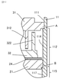
- FIG. 10 is an enlarged view of part A in FIG.
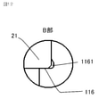
- FIG. 10 is an enlarged view of part B in FIG.
- It is sectional drawing which shows the K part in FIG. It is an enlarged sectional view which shows the main frame and a swing scroll part. It is an enlarged sectional view which shows the main frame and a swing scroll part. It is an enlarged sectional view which shows the main frame and a swing scroll part. It is an enlarged sectional view which shows the main frame and a swing scroll part. It is an enlarged sectional view which shows the main frame and a swing scroll part. It is an enlarged sectional view which shows the main frame and a swing scroll part.
- FIG. 26 is a cross-sectional view taken along the plane passing through the X axis in FIG. 26. It is sectional drawing which shows the main frame. It is a perspective view which looked at the main frame from one end side. It is a perspective view which looked at the main frame from the other end side.
- Embodiment 1 relates to a scroll compressor, and particularly to a structure of a mainframe which is a component of the scroll compressor.
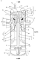
- FIG. 1 is a perspective view showing a scroll compressor
- FIG. 2 is a vertical sectional view showing the scroll compressor
- FIG. 3 is a perspective view showing a middle shell in the scroll compressor
- FIG. 4 is a perspective view showing a main frame
- FIG. It is a perspective view which shows the fixed scroll, and is the figure which looked at the fixed scroll from the lower side.
- 6A and 6B are perspective views showing a swinging scroll
- FIG. 6A is a perspective view showing a case where the swinging scroll is viewed from above
- FIG. 6B is a perspective view showing a case where the swinging scroll is viewed from below.
- 7 is a perspective view showing an old dam ring
- FIG. 8 is a perspective view showing a crankshaft
- FIG. 9 is a perspective view showing a bush.
- the compressor shown in FIG. 1 is a so-called vertical scroll compressor used in a state where the central axis of the crankshaft is substantially perpendicular to the ground.
- the scroll compressor includes a shell 1, a main frame 2, a compression mechanism unit 3, a drive mechanism unit 4, a subframe 5, a crankshaft 6, a bush 7, and a power feeding unit 8.
- the side (upper side) where the compression mechanism unit 3 is provided is directed to one end side
- the side (lower side) where the drive mechanism unit 4 is provided is directed to the other end side.
- the shell 1 is a housing made of metal and closed at both ends, and includes a middle shell 11, an upper shell 12, and a lower shell 13.
- the middle shell 11 is formed in a cylindrical shape, and a suction pipe 14 is connected to the side wall thereof by welding or the like.
- the suction pipe 14 is a pipe that introduces the refrigerant into the shell 1 and communicates with the inside of the middle shell 11.
- the upper shell 12 is formed in a substantially hemispherical shape, and a part of the side wall thereof is connected by welding or the like at the upper end portion of the middle shell 11 to cover the upper opening of the middle shell 11.
- a discharge pipe 15 is connected to the upper part of the upper shell 12 by welding or the like.
- the discharge pipe 15 is a pipe that discharges the refrigerant to the outside of the shell 1 and communicates with the internal space of the middle shell 11.
- the lower shell 13 is formed in a substantially hemispherical shape, and a part of the side wall thereof is connected by welding or the like at the lower end portion of the middle shell 11 to cover the lower opening of the middle shell 11.
- the shell 1 is supported by a fixing base 16 having a plurality of screw holes. A plurality of screw holes are formed in the fixing base 16, and by screwing screws into these screw holes, the scroll compressor can be fixed to other members such as the housing of the outdoor unit.
- the main frame 2 is made of a metal such as cast iron, is formed in a hollow frame in which a cavity is formed, and is provided inside the shell 1.
- the main frame 2 includes a main body portion 21, a main bearing portion 22, and an oil return pipe 23.
- the main body portion 21 is fixed to the inner wall surface on one end side of the middle shell 11, and a storage space 211 is formed in the central portion along the longitudinal direction of the shell 1.
- the accommodation space 211 has a stepped shape in which one end side is open and the space becomes narrower toward the other end side.
- An annular flat surface 212 is formed on one end side of the main body 21 so as to surround the accommodation space 211.
- a ring-shaped thrust plate 24 (see FIG. 10) made of a steel plate-based material such as valve steel is arranged on the flat surface 212. Therefore, in the present embodiment, the thrust plate 24 functions as a thrust bearing.
- the thrust plate 24 functions as a thrust bearing, a detent to suppress rotation is required.
- the flat surface 212 of the main frame 2 may be provided with protrusions thinner than the thickness of the thrust plate 24 to suppress the rotation of the thrust plate 24.
- the structure may be such that a groove is formed in the main frame 2 and a protrusion is formed in the thrust plate 24 to fit both parts.
- a suction port 213 is formed at a position of the main frame 2 that does not overlap with the thrust plate 24 on the outer end side of the flat surface 212.
- the suction port 213 is a space that penetrates the main body portion 21 in the vertical direction, that is, the upper shell 12 side and the lower shell 13 side.
- FIG. 4 shows a case where two suction ports 213 and two oil return pipes 23 are provided, but the number is not limited to this.
- the suction port 213 is a through hole, it may have a notch shape with the outer wall removed.
- An oldham accommodating portion 214 is formed at a step portion on the other end side of the flat surface 212 of the main frame 2.
- a first Oldham groove 215 is formed in the Oldham accommodating portion 214.
- the first Oldham groove 215 is formed so that a part of the outer end side is cut off from the inner end side of the flat surface 212. Therefore, when the main frame 2 is viewed from one end side, a part of the first Oldham groove 215 overlaps with the thrust plate 24.
- the pair of two first Oldham grooves 215 are formed so as to face each other.
- the main bearing portion 22 is continuously formed on the other end side of the main body portion 21, and a shaft hole 221 is formed inside the main bearing portion 22.
- the shaft hole 221 penetrates the main bearing portion 22 in the vertical direction, and one end side thereof communicates with the accommodation space 211.
- the oil return pipe 23 is a pipe for returning the lubricating oil accumulated in the accommodation space 211 to the oil reservoir provided inside the lower shell 13, and is inserted and fixed in the oil drain hole formed through the inside and outside of the main frame 2. Has been done.
- the lubricating oil is, for example, a refrigerating machine oil containing an ester-based synthetic oil.
- Lubricating oil is stored in the lower part of the shell 1, that is, in the lower shell 13, is sucked up by the oil pump 52 described later, passes through the oil passage 63 provided in the crankshaft 6, and is mechanically such as the compression mechanism portion 3. It reduces the wear between parts that come into contact with the oil, regulates the temperature of the sliding part, and further improves the sealing performance.
- As the lubricating oil an oil having excellent lubrication characteristics, electrical insulation, stability, refrigerant solubility, low temperature fluidity and the like and having an appropriate viscosity is suitable.
- the compression mechanism unit 3 is a compression mechanism that compresses the refrigerant.
- the compression mechanism unit 3 is a scroll compression mechanism including a fixed scroll 31 and a swing scroll 32.
- the fixed scroll 31 is made of a metal such as cast iron and includes a first substrate 311 and a first spiral body 312.
- the first substrate 311 is formed in a disk shape, and a discharge port 313 is formed in the center thereof so as to penetrate in the vertical direction.
- the first spiral body 312 protrudes from the other end side surface of the first substrate 311 to form a spiral wall, and the tip thereof protrudes toward the other end side.
- the rocking scroll 32 is made of a metal such as aluminum and includes a second substrate 321, a second spiral body 322, a cylindrical portion 323, and a second Oldham groove 324. ..
- the second substrate 321 is located on one surface on which the second spiral body 322 is formed, the other surface on which at least a part of the outer peripheral region is the sliding surface 3211, and the outermost surface in the radial direction. It is formed in the shape of a disk having a side surface 3212 connecting the surface and the other surface.
- the sliding surface 3211 on the other surface is configured to be slidable with respect to the thrust plate 24, and is supported (supported) by the main frame 2.
- the second spiral body 322 protrudes from one surface of the second substrate 321 to form a spiral wall, and the tip thereof protrudes to one end side.
- a seal member for suppressing leakage of the refrigerant is provided at the tip of the first spiral body 312 of the fixed scroll 31 and the second spiral body 322 of the rocking scroll 32.
- the tubular portion 323 is a cylindrical boss formed so as to project from substantially the center of the other surface of the second substrate 321 toward the other end side.
- a swing bearing that rotatably supports the slider 71 described later, a so-called journal bearing, is provided so that its central axis is parallel to the central axis of the crankshaft 6. ..
- the second Oldham groove 324 is formed on the other surface of the second substrate 321 and is a rectangular groove in which one surface is formed in an arc shape.
- the two second Oldham grooves 324 constituting the pair are provided so as to face each other.
- the line connecting the two second Oldham grooves 324 constituting the pair is provided so as to be orthogonal to the line connecting the two first Oldam grooves 215 forming the pair.
- An old dam ring 33 is arranged in the old dam accommodating portion 214 provided in the main frame 2.
- the oldam ring 33 includes a ring portion 331, a first key portion 332, and a second key portion 333.
- the ring portion 331 is formed in a ring shape.
- two first key portions 332 forming a pair are formed so as to face each other on the surface on the other end side of the ring portion 331, and two pieces forming a pair of the main frame 2 are formed. It is housed in the first Oldham ditch 215.
- the two second key portions 333 that form a pair are formed so as to face each other on the surface on one end side of the ring portion 331, and the two that form a pair of the swing scroll 32. It is housed in the second Oldham ditch 324.
- the compression chamber 34 is formed by engaging the first spiral body 312 of the fixed scroll 31 and the second spiral body 322 of the rocking scroll 32 with each other. Since the volume of the compression chamber 34 decreases from the outside to the inside in the radial direction, the refrigerant is gradually compressed by being taken in from the outer end side of the spiral body and moved to the center side.
- the compression chamber 34 communicates with the discharge port 313 at the central portion of the fixed scroll 31.
- a muffler 35 having a discharge hole 351 is provided on the surface on one end side of the fixed scroll 31, and a discharge valve 36 that opens and closes the discharge hole 351 in a predetermined case to prevent backflow of the refrigerant is provided. ..
- the refrigerant includes, for example, a halogenated hydrocarbon having a carbon double bond in the composition, a halogenated hydrocarbon having no carbon double bond, a hydrocarbon, and a mixture containing them.
- Examples of the halogenated hydrocarbon having a carbon double bond correspond to an HFC refrigerant having a zero ozone depletion potential and a freon-based low GWP refrigerant, and tetrafluoro such as HFO1234yf, HFO1234ze, and HFO1243zf having a chemical formula of C3H2F4.
- Propen is an example.
- Examples of the halogenated hydrocarbon having no carbon double bond include a refrigerant mixed with R32 (difluoromethane) represented by CH2F2 and R41 and the like.
- Examples of the hydrocarbon include propane and propylene, which are natural refrigerants.
- Examples of the mixture include a mixed refrigerant in which R32, R41 and the like are mixed with HFO1234yf, HFO1234ze, HFO1243zf and the like.
- the drive mechanism unit 4 is provided on the other end side of the main frame 2 inside the shell 1.
- the drive mechanism unit 4 includes a stator 41 and a rotor 42.
- the stator 41 is a stator formed by winding windings around an iron core formed by laminating a plurality of electrical steel sheets, for example, via an insulating layer, and is formed in a ring shape.
- the stator 41 is fixedly supported inside the middle shell 11 by shrink fitting or the like.
- the rotor 42 is a cylindrical one having a permanent magnet built in an iron core formed by laminating a plurality of electromagnetic steel sheets and having a through hole penetrating in the vertical direction in the center, and is arranged in the internal space of the stator 41. There is.
- the subframe 5 is a frame made of metal such as cast iron, and is provided on the other end side with respect to the drive mechanism portion 4 inside the shell 1.
- the subframe 5 is fixedly supported on the inner peripheral surface on the other end side of the middle shell 11 by shrink fitting, welding, or the like.
- the subframe 5 includes an auxiliary bearing portion 51 and an oil pump 52.
- the auxiliary bearing portion 51 is a ball bearing provided on the upper side of the central portion of the subframe 5, and has a hole penetrating in the vertical direction in the center.
- the oil pump 52 is provided below the central portion of the subframe 5, and is arranged so that at least a part of the oil pump 52 is immersed in the lubricating oil stored in the oil reservoir of the shell 1.
- a ball bearing is shown as the auxiliary bearing portion 51 in FIG. 2, this may be, for example, a journal bearing.
- the crankshaft 6 is a long rod-shaped metal member, which is provided inside the shell 1.
- the crankshaft 6 includes a main shaft portion 61, an eccentric shaft portion 62, and an oil passage 63.
- the main shaft portion 61 is a shaft constituting the main portion of the crankshaft 6, and the central shaft thereof is arranged so as to coincide with the central shaft of the middle shell 11.
- a rotor 42 is contact-fixed to the outer surface of the spindle portion 61.
- the eccentric shaft portion 62 is provided on one end side of the spindle portion 61 so that the central axis of the eccentric shaft portion 62 is eccentric with respect to the central axis of the spindle portion 61.
- the oil passage 63 is provided so as to vertically penetrate the inside of the spindle portion 61 and the eccentric shaft portion 62.
- one end side of the spindle portion 61 is inserted into the main bearing portion 22 of the main frame 2, and the other end side is inserted and fixed into the sub bearing portion 51 of the subframe 5.
- the eccentric shaft portion 62 is arranged in the cylinder of the tubular portion 323 of the swing scroll 32.
- the outer peripheral surface of the rotor 42 is arranged with a predetermined gap from the inner peripheral surface of the stator 41.
- a first balancer 64 is provided on one end side of the spindle portion 61, and a second balancer 65 is provided on the other end side in order to cancel the imbalance caused by the swing of the swing scroll 32.
- the bush 7 is made of a metal such as iron, and is a connecting member for connecting the swing scroll 32 and the crankshaft 6.
- the bush 7 is composed of two parts in FIG. 9, that is, includes a slider 71 and a balance weight 72.
- the slider 71 is a tubular member having a flange portion formed therein, and is fitted into each of the eccentric shaft portion 62 and the tubular portion 323.
- the balance weight 72 is a donut-shaped member having a weight portion 721 having a substantially C-shaped shape when viewed from one end side, and is biased with respect to the center of rotation in order to offset the centrifugal force of the swing scroll 32. It is provided with a core.
- the balance weight 72 is fitted to the flange portion of the slider 71 by a method such as shrink fitting.
- the slider 71 and the balance weight 72 may be integrally machined and configured as one component by machining, for example.
- the feeding unit 8 is a feeding member that supplies power to the scroll compressor, and is formed on the outer peripheral surface of the middle shell 11 of the shell 1.
- the power feeding unit 8 includes a cover 81, a power feeding terminal 82, and a wiring 83.
- the cover 81 is a cover member having a bottom and an opening.
- the power feeding terminal 82 is made of a metal member, one of which is provided inside the cover 81 and the other of which is provided inside the shell 1.
- One of the wiring 83 is connected to the power feeding terminal 82, and the other is connected to the stator 41.
- FIG. 10 is a cross-sectional view showing the K portion in FIG. 2.
- 11 is an enlarged view of part A in FIG. 10
- FIG. 12 is an enlarged view of part B in FIG.
- the middle shell 11 has a first protruding portion 112 that protrudes radially from the first inner wall surface 111.
- the middle shell 11 has a first positioning surface 113 which is in contact with the first substrate 311 of the fixed scroll 31 and determines the axial position of the fixed scroll 31 at the end surface of the first protruding portion 112 facing the upper shell 12 side.
- the middle shell 11 has a second inner wall surface 114 which is an inner wall surface of the first protruding portion 112, and a second protruding portion 115 which further protrudes in the radial direction from the first protruding portion 112. Further, the middle shell 11 is an end surface of the second protruding portion 115 facing the upper shell 12 side, and is in contact with the main body portion 21 of the main frame 2 to be contacted with the second positioning surface 116 that determines the axial position of the main frame 2. It has a third inner wall surface 117 which is an inner wall surface of the second protruding portion 115.
- the middle shell 11 has a stepped portion whose inner diameter decreases toward the other end side.
- the first positioning surface 113 and the second positioning surface 116 are formed so as to be substantially perpendicular to the central axis of the crankshaft 6, and the normal vectors of both positioning surfaces are formed so as to face the same direction. ing.
- the first protrusion 112 is fitted with the protrusion 314 of the fixed scroll 31 described later and the protrusion 216 of the main frame 2 to form a groove 118 that determines the phase of both parts. ..
- a chamfered portion 1181 is formed at the tip of the groove 118 on the upper shell 12 side by C chamfering (cutting the corners with a right-angled isosceles triangle) or R chamfering (chamfering in an arc shape), and the groove width is gradually reduced from the tip. It's narrowing.
- the chamfered portion 1181 serves as a guide, and it becomes easy to guide the protrusion 216 of the main frame 2 and the protrusion 314 of the fixed scroll 31, so that the assembly becomes easy and the assembleability of the compressor is improved.
- a recess 1131 and a recess 1161 are provided at the corner where the first positioning surface 113 and the first inner wall surface 111 intersect, and at the corner where the second positioning surface 116 and the second inner wall surface 114 intersect, respectively.
- the fixed scroll 31 and the main frame 2 can be reliably brought into contact with each positioning surface.
- the main frame 2 has a protrusion 216 protruding in the radial direction from the outer diameter of the main body portion 21.
- FIG. 13 is an enlarged perspective view showing a protruding portion.
- a C-chamfered or R-chamfered chamfered portion 2161 is formed at the tip of the protrusion 216 on the lower shell 13 side, and the protrusion width is gradually widened from the tip.
- the phase of the main frame 2 is determined by fitting the protrusion 216 with the groove 118 formed in the middle shell 11. Further, the position of the main frame 2 in the axial direction is determined by bringing the main body 21 of the main frame 2 into contact with the second positioning surface 116 formed on the middle shell 11.
- the center position is determined by press-fitting and shrink-fitting the main frame 2 to the second inner wall surface 114 or the third inner wall surface 117 of the middle shell 11. If the holding force is insufficient, arc spot welding or the like may be further performed.
- the main frame 2 can be held by the middle shell 11 in a state where the center position, the height position in the axial direction, and the phase are determined with respect to the middle shell 11.
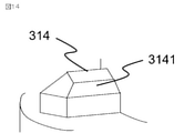
- the fixed scroll 31 has a protrusion 314 protruding from the surface of the first substrate 311 on the side forming the first spiral body 312 toward the lower shell 13.
- FIG. 14 is an enlarged perspective view showing a protruding portion.
- a C-chamfered or R-chamfered chamfered portion 3141 is formed at the tip of the protrusion 314 on the lower shell 13 side, and the protrusion width is gradually widened from the tip.
- the phase of the fixed scroll 31 is determined by fitting the protrusion 314 into the groove 118 formed in the middle shell 11. Further, as shown in FIG.
- the fixed scroll 31 is formed by bringing the surface of the first substrate 311 of the fixed scroll 31 on the side forming the first spiral body 312 into contact with the first positioning surface 113 formed on the middle shell 11.
- the axial position of is determined.
- the center position is determined by fixing the side surface 3111 of the first substrate 311 to the first inner wall surface 111 of the middle shell 11 by shrink fitting.
- the fixed scroll 31 can be held in the middle shell 11 in a state where the center position, the height position in the axial direction, and the phase with respect to the middle shell 11 are determined. Further, the fixed scroll 31 has a function of separating high pressure and low pressure inside the shell 1.
- the shrink fitting position is set to the first inner wall surface 111 in which the groove 118 is not formed.
- FIG. 15 is a cross-sectional view showing the K portion in FIG. 2 as in FIG. 10, and shows the dimensions of each component.
- the tooth tip clearance Q can be expressed by the following formula.
- the target tooth tip clearance Q can be obtained by adjusting the thickness T of the thrust plate 24, which is capable of producing the widest variety and large quantities.
- the target tooth tip clearance Q here is 71 ⁇ 5 ⁇ m as a guide.
- this value is a numerical value of a representative model, and the target value changes for each model.
- FIGS. 16 to 19 are enlarged cross-sectional views showing the main frame 2 and the swing scroll 32 portion.
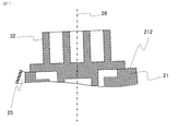
- the Z-axis 28 shown in FIGS. 16 to 19 is a straight line that is perpendicular to the flat surface 212 of the main frame 2 and passes through the center of the outer diameter portion where the stress F is generated.
- the swing scroll 32 is placed on the main frame 2. In this state, as shown in FIG. 16, stress F due to shrink fitting of the middle shell 11 is generated in the surface of the outer diameter portion of the main frame 2, and the flat surface 212 of the main frame 2 is deformed as shown in FIG. do.
- FIG. 17 shows the deformation of the main frame 2 when the suction port 213 as a portion having low rigidity against the bending moment due to the stress F generated by the compressive load applied in the radial direction is on one side of the Z axis 28.
- the portion 25 that has lower rigidity than the other components of the mainframe 2 includes a pin hole for positioning required during machining, a hole that suppresses vibration during vibration, an old dam groove, and a fixed scroll. There are holes for determining the phase.
- FIG. 18 and 19 show the deformation of the main frame 2 when the low-rigidity portions 25 are on both sides of the Z-axis 28.
- a portion having low rigidity is compared with the flatness of the flat surface 212 at the time of deformation of the main frame 2 when the portion 25 having low rigidity is on one side of the Z axis 28.
- the flatness of the flat surface 212 at the time of deformation of the main frame 2 is improved. Therefore, when the flat surface 212 of the main frame 2 is used as a reference surface, the inclination of the rocking scroll 32 with respect to the flat surface 212 when the rocking scroll 32 is provided on the main frame 2 becomes small.
- the tooth tip clearance Q can be assembled with high accuracy, leakage to the adjacent compression space can be suppressed, and the loss of the scroll compressor can be reduced. Further, since the deterioration of the flatness of the flat surface 212 of the main frame 2 can be suppressed, the increase in the sliding resistance of the swing scroll 32 can be suppressed, and the deterioration of the performance of the scroll compressor can be suppressed.
- FIG. 20 is a plan view showing a mainframe
- FIG. 21 is a cross-sectional view cut along a plane passing through the X-axis 26 in FIG.
- the Z-axis 28 is a straight line that is perpendicular to the flat surface 212 of the main frame 2 and passes through the center of the outer peripheral surface of the main frame 2.
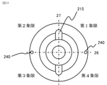
- the Y-axis 27 is a straight line that passes through the center of the first Oldham groove 215 and intersects the Z-axis 28.
- the X-axis 26 is a straight line perpendicular to the Y-axis 27 and is a straight line intersecting the Z-axis 28.
- the second portion 252 having low rigidity is provided over the first quadrant and the fourth quadrant.
- the pair of low-rigidity portions 251 and 252 are located symmetrically with respect to the Y-axis 27 and face each other with the Z-axis 28, which is the central axis of the main frame 2, interposed therebetween. That is, the first portion 251 having low rigidity, which is a portion having two low rigidity on both the left and right sides with respect to the Y axis (first axis) which is a straight line passing through the center of the first Oldham groove 215 and intersecting the Z axis 28.
- a second portion 252 having low rigidity is provided, and a straight line perpendicular to the Y-axis 27 and intersecting the Z-axis 28, which is a straight line passing through the center of the outer peripheral surface of the main frame 2, is the X-axis 26 (the second).
- the first portion 251 having low rigidity and the second portion 252 having low rigidity are arranged so as to straddle the X-axis 26.
- the portions 251 and 252 having low rigidity of the main frame 2 are shown as having the same shape.
- the hole 220 can be provided. Further, it can be configured asymmetrically with respect to the X-axis 26 or the Y-axis 27 as compared with the shape of the portion 25 having low rigidity. Further, it can be set to a different shape or a different number.
- the shape of the portion 25 having low rigidity may be a hole, a notch, a groove, or a suction port 213.
- FIG. 23 is a plan view showing a case where the notch 230 is provided.
- FIG. 24 is a plan view showing a case where the hole 240 is provided.
- FIG. 25 is a plan view showing a case where the groove 250 is provided. These are provided in order to suppress deterioration of the flatness of the flat surface 212 of the main frame 2.
- the portion 25 having low rigidity is the suction port 213, it is desirable that a part of the suction port 213 is located outside the locus of the swing scroll 32 when the swing scroll 32 swings, in order to allow the refrigerant to penetrate the main frame 2.
- the second substrate 321 of the swing scroll 32 does not block the passage of the refrigerant. That is, when the suction port 213 corresponds to the portion having low rigidity, the portion 25 having low rigidity is located on the outer diameter side of the swing scroll 32.
- FIG. 26 is a plan view showing a mainframe
- FIG. 27 is a cross-sectional view cut along a plane passing through the X axis in FIG. 26.
- the Z-axis 28 is a straight line perpendicular to the flat surface 212 of the main frame 2 and passing through the center of the outer diameter.
- the Y-axis 27 is a straight line that passes through the center of the first Oldham groove 215 and intersects the Z-axis 28.
- the X-axis 26 is a straight line perpendicular to the Y-axis 27 and intersects the Z-axis 28.
- the low-rigidity portion 25 of the main frame 2 is provided over the second quadrant and the third quadrant, as shown in FIG. 27, over the second quadrant and the third quadrant.
- a portion 100 having high rigidity is provided.
- a thick portion 100 provided along the circumferential direction over the second and third quadrants is a portion having high rigidity, and this portion is a rib. That is, the high-rigidity portion 100 is provided at a position corresponding to the circumferential position of the low-rigidity portion 25 of the main frame 2.
- the position corresponding to the circumferential position refers to the angle range ⁇ in which the low-rigidity portion 25 is provided in FIG.
- the high-rigidity portion 100 is provided in the same angle range ⁇ .
- the moment of inertia of area with respect to the bending moment caused by the stress F generated by the compressive load applied in the radial direction is larger than the moment of inertia of area of the cross section in the first and fourth quadrants.
- the rigidity in the second and third quadrants is higher than that in the first and fourth quadrants.
- the low-rigidity portion 25 and the high-rigidity portion 100 are located in the same phase (the positions corresponding to the circumferential positions are the same). In this case, they are only in the same phase, and there are degrees of freedom in the radial direction.
- the high-rigidity portion 100 may be asymmetrical with respect to the X-axis 26 and the Y-axis 27, have a different shape, or may have a different number.
- FIG. 28 shows a case where the bracket 281 is attached by a screw 280 as a separate member.
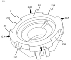
- FIG. 29 is a perspective view of the main frame as viewed from one end side (see FIG. 2)
- FIG. 30 is a perspective view of the main frame as viewed from the other end side
- FIGS. 31 and 32 are views of the main frame from the other end side. It is a plan view.
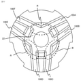
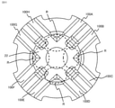
- the main frame 2 is provided with ribs 100A, 100B, 100C, 100D, 100E, and 100F, which are portions having high rigidity.
- the ribs 100A, 100B, 100C, 100D, 100E, 100F, the main body portion 21, and the main bearing portion 22, which are the parts having high rigidity of the main frame 2 are dotted (FIG. 30).
- the truss structures 29A, 29B, and 29C are configured.
- the rib 100A, the main bearing portion 22, the rib 100F and the main body portion 21 are composed, the rib 100F and the main body portion 21 are rigidly joined by the contact 29A1, and the rib 100A and the main body portion 21 are rigidly joined.
- the rib 100F and the main bearing portion 22 and the rib 100A and the main bearing portion 22 are rigidly joined by the contact 29A2.
- the truss structures 29B and 29C are similarly configured.
- the contacts 29A1, 29A2 ... 29C3 are rigidly joined to form the truss structures 29A, 29B and 29C.
- ribs 100A, 100B, 100C, 100D, 100E, and 100F which are highly rigid portions, are provided from the main body portion 21 of the main frame 2 toward the main bearing portion 22. That is, one end side of the ribs 100A, 100B, 100C, 100D, 100E, 100F on the main body 21 side, which is a connection between the ribs 100A, 100B, 100C, 100D, 100E, 100F and the main body 21 of the main frame 2. Is connected to the portion where the mainframe 2 is in contact with the shell 1.
- the axial direction means the vertical direction in which the compressor as shown in FIG. 2 is attached.
- the circumferential position of the rib 100A, 100B, 100C, 100D, 100E, 100F on the axial end side of the main body 21 side is within the circumferential range of the main body 21 to which stress is applied (for example, in FIG. 31, the rib 100A).
- the circumferential position of the other end side in the axial direction on the portion 22 side is within the circumferential direction range of the portions 25A, 25B, and 25C having low rigidity (for example, the circumferential direction on the other end side of the main bearing portion 22 side of the rib 100A).
- the position is within the circumferential range 300 of the less rigid portion 25A).
- the ribs 100A and 100B are provided symmetrically from the center Q of the surface of the main body 21 in contact with the shell 1. The same applies to the ribs 100C and 100D, and the ribs 100E and 100F.
- the truss structure 29A is composed of a main body portion 21, highly rigid portions 100A and 100F, and a main bearing portion 22 as shown by a dotted line.
- the truss structure 29B is composed of a main body portion 21, highly rigid portions 100B and 100C, and a main bearing portion 22 as shown by a dotted line like the truss structure 29A.
- the truss structure 29C is composed of a main body portion 21, highly rigid portions 100D and 100E, and a main bearing portion 22 as shown by dotted lines like the truss structures 29A and 29B. Further, as shown in FIGS.
- the adjacent ribs 100A and the other end side of the 100F on the main bearing portion 22 side in the axial direction are connected to each other.
- the adjacent ribs 100B and 100C are connected to each other on the other end side in the axial direction on the main bearing portion 22 side.
- the adjacent ribs 100D and 100E are connected to each other on the other end side in the axial direction on the main bearing portion 22 side.
- the adjacent ribs 100A and 100F are provided so as to be in contact with each other at the dotted line portion R portion of the main bearing portion 22. This also applies to the relationship between the ribs 100B and 100C, and further the relationship between the ribs 100D and 100E.
- FIG. 33 is a perspective view of the main frame viewed from one end side
- FIG. 34 is a perspective view of the main frame viewed from the other end side
- FIGS. 35 and 36 are plan views of the main frame viewed from the other end side. ..
- the main frame 2 is provided with highly rigid portions 100A, 100B, 100C, 100D, 100E, 100F, 100G, and 100H.
- the ribs 100A, 100B, 100C, 100D, 100E, 100F, 100G, 100H, the main body portion 21, and the main bearing portion 22, which are the parts having high rigidity of the main frame 2 are used.
- the truss structures 29A, 29B, 29C, and 29D are configured.
- the rib 100A, the main bearing portion 22, the rib 100H and the main body portion 21 are composed, the rib 100H and the main body portion 21 are rigidly joined by the contact 29A1, and the rib 100A and the main body portion 21 are rigidly joined.
- the rib 100H and the main bearing portion 22 and the rib 100A and the main bearing portion 22 are rigidly joined by the contact 29A2.
- the truss structures 29B, 29C, and 29D are similarly configured.
- the contacts 29A1, 29A2 ... 29D3 are rigidly joined to form the truss structures 29A, 29B, 29C and 29D.
- 100A, 100B, 100C, 100D, 100E, 100F, 100G, and 100H which are highly rigid portions, are provided from the main body portion 21 of the main frame 2 toward the main bearing portion 22. That is, the main body in the ribs 100A, 100B, 100C, 100D, 100E, 100F, 100G, 100H, which is the connection portion between the ribs 100A, 100B, 100C, 100D, 100E, 100F, 100G, 100H and the main body portion 21 of the main frame 2.
- One end side in the axial direction on the portion 21 side is connected to a portion where the main frame 2 is in contact with the shell 1.
- the axial direction means the vertical direction in which the compressor as shown in FIG.
- the circumferential position of the rib 100A, 100B, 100C, 100D, 100E, 100F, 100G, 100H on the axial end side of the main body 21 side is the position of the main body 21 to which stress is applied. It is within the circumferential range.
- the ribs 100A, 100B which are the connecting portions between the main bearing portion 22 side of the ribs 100A, 100B, 100C, 100D, 100E, 100F, 100G, 100H and the main bearing portion 22 of the main frame 2,
- the circumferential position on the other end side in the axial direction on the main bearing portion 22 side is within the circumferential range of the portions 25A, 25B, 25C, and 25D having low rigidity.
- the ribs 100A and 100B are provided symmetrically from the center of the surface of the main body 21 in contact with the shell 1.
- the truss structure 29A is composed of a main body portion 21, highly rigid portions 100A and 100H, and a main bearing portion 22.
- the truss structure 29B is composed of a main body portion 21, highly rigid portions 100B and 100C, and a main bearing portion 22 as shown by a dotted line like the truss structure 29A.
- the truss structure 29C is composed of a main body portion 21, highly rigid portions 100D and 100E, and a main bearing portion 22 as shown by dotted lines like the truss structures 29A and 29B.
- the truss structure 29D is also composed of a main body portion 21, highly rigid portions 100F, 100G, and a main bearing portion 22, as shown by dotted lines, like the truss structures 29A, 29B, and 29C.
- the adjacent ribs 100A and 100H are connected to each other on the other end side in the axial direction on the main bearing portion 22 side.
- the adjacent ribs 100B and 100C are connected to each other on the other end side in the axial direction on the main bearing portion 22 side.
- the adjacent ribs 100D and 100E are connected to each other on the other end side in the axial direction on the main bearing portion 22 side.
- the adjacent ribs 100F and the other end side of 100G on the main bearing portion 22 side in the axial direction are connected to each other.
- the adjacent ribs 100A and 100H are provided so as to be in contact with each other at the dotted line portion R portion of the main bearing portion 22. This also applies to the relationship between the ribs 100B and 100C, the relationship between the ribs 100D and 100E, and further the relationship between the ribs 100F and 100G.
Landscapes
- Engineering & Computer Science (AREA)
- Mechanical Engineering (AREA)
- General Engineering & Computer Science (AREA)
- Rotary Pumps (AREA)
- Applications Or Details Of Rotary Compressors (AREA)
Priority Applications (4)
| Application Number | Priority Date | Filing Date | Title |
|---|---|---|---|
| DE112021004542.3T DE112021004542T5 (de) | 2020-09-02 | 2021-08-25 | Spiralkompressor |
| JP2022546260A JP7321384B2 (ja) | 2020-09-02 | 2021-08-25 | スクロール圧縮機 |
| CN202180052658.5A CN116157600B (zh) | 2020-09-02 | 2021-08-25 | 涡旋压缩机 |
| GB2302459.9A GB2612265B (en) | 2020-09-02 | 2021-08-25 | Scroll compressor |
Applications Claiming Priority (2)
| Application Number | Priority Date | Filing Date | Title |
|---|---|---|---|
| JP2020147233 | 2020-09-02 | ||
| JP2020-147233 | 2020-09-02 |
Publications (1)
| Publication Number | Publication Date |
|---|---|
| WO2022050142A1 true WO2022050142A1 (ja) | 2022-03-10 |
Family
ID=80490908
Family Applications (1)
| Application Number | Title | Priority Date | Filing Date |
|---|---|---|---|
| PCT/JP2021/031100 Ceased WO2022050142A1 (ja) | 2020-09-02 | 2021-08-25 | スクロール圧縮機 |
Country Status (5)
| Country | Link |
|---|---|
| JP (1) | JP7321384B2 (https=) |
| CN (1) | CN116157600B (https=) |
| DE (1) | DE112021004542T5 (https=) |
| GB (1) | GB2612265B (https=) |
| WO (1) | WO2022050142A1 (https=) |
Cited By (1)
| Publication number | Priority date | Publication date | Assignee | Title |
|---|---|---|---|---|
| CN117072442A (zh) * | 2022-05-10 | 2023-11-17 | 苏州英华特涡旋技术股份有限公司 | 可控变形的主轴承座及包括该主轴承座的压缩机 |
Citations (6)
| Publication number | Priority date | Publication date | Assignee | Title |
|---|---|---|---|---|
| JPH08193581A (ja) * | 1995-01-17 | 1996-07-30 | Hitachi Ltd | スクロール流体機械 |
| JPH08219043A (ja) * | 1995-02-16 | 1996-08-27 | Zexel Corp | スクロール型コンプレッサ |
| JPH1122657A (ja) * | 1997-06-30 | 1999-01-26 | Sanyo Electric Co Ltd | スクロール圧縮機 |
| JP2002317776A (ja) * | 2001-04-20 | 2002-10-31 | Fujitsu General Ltd | スクロール圧縮機 |
| JP2012219654A (ja) * | 2011-04-05 | 2012-11-12 | Daikin Industries Ltd | 回転式流体機械 |
| WO2019207759A1 (ja) * | 2018-04-27 | 2019-10-31 | 三菱電機株式会社 | スクロール圧縮機 |
Family Cites Families (5)
| Publication number | Priority date | Publication date | Assignee | Title |
|---|---|---|---|---|
| JP2004225569A (ja) * | 2003-01-21 | 2004-08-12 | Fujitsu General Ltd | スクロール圧縮機 |
| JP4980412B2 (ja) * | 2009-11-26 | 2012-07-18 | 三菱電機株式会社 | スクロール圧縮機 |
| WO2016104336A1 (ja) * | 2014-12-24 | 2016-06-30 | 株式会社ヴァレオジャパン | 電動スクロール圧縮機 |
| JP6715722B2 (ja) * | 2016-07-29 | 2020-07-01 | 日立ジョンソンコントロールズ空調株式会社 | スクロール圧縮機 |
| CN109863307B (zh) | 2016-10-28 | 2020-11-03 | 三菱电机株式会社 | 涡旋式压缩机、制冷循环装置以及壳体 |
-
2021
- 2021-08-25 DE DE112021004542.3T patent/DE112021004542T5/de active Pending
- 2021-08-25 CN CN202180052658.5A patent/CN116157600B/zh active Active
- 2021-08-25 GB GB2302459.9A patent/GB2612265B/en active Active
- 2021-08-25 JP JP2022546260A patent/JP7321384B2/ja active Active
- 2021-08-25 WO PCT/JP2021/031100 patent/WO2022050142A1/ja not_active Ceased
Patent Citations (6)
| Publication number | Priority date | Publication date | Assignee | Title |
|---|---|---|---|---|
| JPH08193581A (ja) * | 1995-01-17 | 1996-07-30 | Hitachi Ltd | スクロール流体機械 |
| JPH08219043A (ja) * | 1995-02-16 | 1996-08-27 | Zexel Corp | スクロール型コンプレッサ |
| JPH1122657A (ja) * | 1997-06-30 | 1999-01-26 | Sanyo Electric Co Ltd | スクロール圧縮機 |
| JP2002317776A (ja) * | 2001-04-20 | 2002-10-31 | Fujitsu General Ltd | スクロール圧縮機 |
| JP2012219654A (ja) * | 2011-04-05 | 2012-11-12 | Daikin Industries Ltd | 回転式流体機械 |
| WO2019207759A1 (ja) * | 2018-04-27 | 2019-10-31 | 三菱電機株式会社 | スクロール圧縮機 |
Cited By (1)
| Publication number | Priority date | Publication date | Assignee | Title |
|---|---|---|---|---|
| CN117072442A (zh) * | 2022-05-10 | 2023-11-17 | 苏州英华特涡旋技术股份有限公司 | 可控变形的主轴承座及包括该主轴承座的压缩机 |
Also Published As
| Publication number | Publication date |
|---|---|
| JP7321384B2 (ja) | 2023-08-04 |
| GB2612265B (en) | 2024-05-15 |
| GB202302459D0 (en) | 2023-04-05 |
| DE112021004542T5 (de) | 2023-06-29 |
| GB2612265A (en) | 2023-04-26 |
| JPWO2022050142A1 (https=) | 2022-03-10 |
| CN116157600B (zh) | 2025-09-19 |
| CN116157600A (zh) | 2023-05-23 |
Similar Documents
| Publication | Publication Date | Title |
|---|---|---|
| WO2018078787A1 (ja) | スクロール圧縮機、冷凍サイクル装置およびシェル | |
| WO2018163233A1 (ja) | スクロール圧縮機および冷凍サイクル装置 | |
| WO2022050142A1 (ja) | スクロール圧縮機 | |
| JP7076536B2 (ja) | スクロール圧縮機 | |
| JP2021076085A (ja) | スクロール圧縮機 | |
| JP7118177B2 (ja) | スクロール圧縮機 | |
| JP6986998B2 (ja) | スクロール圧縮機、冷凍装置及び空調装置 | |
| JP6745994B2 (ja) | スクロール圧縮機および冷凍サイクル装置 | |
| JP7433697B2 (ja) | スクロール圧縮機及び当該スクロール圧縮機を使用した冷凍サイクル装置 | |
| JPWO2020161965A1 (ja) | 回転式圧縮機、回転式圧縮機の製造方法及び冷凍サイクル装置 | |
| JP7727004B2 (ja) | スクロール圧縮機およびその製造方法 | |
| JP6903228B2 (ja) | スクロール圧縮機及び冷凍サイクル装置 | |
| JP7450753B2 (ja) | スクロール圧縮機およびスクロール圧縮機の組立方法 | |
| JPWO2019207785A1 (ja) | スクロール圧縮機 | |
| JP7361585B2 (ja) | スクロール圧縮機及びスクロール圧縮機の製造方法 | |
| JP7621510B2 (ja) | スクロール圧縮機 | |
| WO2021009839A1 (ja) | スクロール圧縮機 | |
| WO2022145185A1 (ja) | スクロール圧縮機の製造方法およびスクロール圧縮機 | |
| WO2021014641A1 (ja) | スクロール圧縮機 | |
| JP7191246B2 (ja) | スクロール圧縮機および冷凍サイクル装置 | |
| WO2019207760A1 (ja) | スクロール圧縮機 | |
| WO2023188422A1 (ja) | 圧縮機およびアッパーシェル | |
| JP2024061302A (ja) | 電動圧縮機 | |
| WO2018150525A1 (ja) | スクロール圧縮機 | |
| JP2008025391A (ja) | スクロール流体機械 |
Legal Events
| Date | Code | Title | Description |
|---|---|---|---|
| 121 | Ep: the epo has been informed by wipo that ep was designated in this application |
Ref document number: 21864200 Country of ref document: EP Kind code of ref document: A1 |
|
| ENP | Entry into the national phase |
Ref document number: 2022546260 Country of ref document: JP Kind code of ref document: A |
|
| ENP | Entry into the national phase |
Ref document number: 202302459 Country of ref document: GB Kind code of ref document: A Free format text: PCT FILING DATE = 20210825 |
|
| WWE | Wipo information: entry into national phase |
Ref document number: 2302459.9 Country of ref document: GB |
|
| WWP | Wipo information: published in national office |
Ref document number: 2302459.9 Country of ref document: GB |
|
| 122 | Ep: pct application non-entry in european phase |
Ref document number: 21864200 Country of ref document: EP Kind code of ref document: A1 |
|
| WWG | Wipo information: grant in national office |
Ref document number: 2302459.9 Country of ref document: GB |
|
| WWG | Wipo information: grant in national office |
Ref document number: 202180052658.5 Country of ref document: CN |