WO2022044885A1 - 走行支援装置 - Google Patents
走行支援装置 Download PDFInfo
- Publication number
- WO2022044885A1 WO2022044885A1 PCT/JP2021/030029 JP2021030029W WO2022044885A1 WO 2022044885 A1 WO2022044885 A1 WO 2022044885A1 JP 2021030029 W JP2021030029 W JP 2021030029W WO 2022044885 A1 WO2022044885 A1 WO 2022044885A1
- Authority
- WO
- WIPO (PCT)
- Prior art keywords
- vehicle
- target
- steering
- collision
- primary
- Prior art date
- Legal status (The legal status is an assumption and is not a legal conclusion. Google has not performed a legal analysis and makes no representation as to the accuracy of the status listed.)
- Ceased
Links
Images


Classifications
-
- B—PERFORMING OPERATIONS; TRANSPORTING
- B62—LAND VEHICLES FOR TRAVELLING OTHERWISE THAN ON RAILS
- B62D—MOTOR VEHICLES; TRAILERS
- B62D15/00—Steering not otherwise provided for
- B62D15/02—Steering position indicators ; Steering position determination; Steering aids
- B62D15/025—Active steering aids, e.g. helping the driver by actively influencing the steering system after environment evaluation
- B62D15/0265—Automatic obstacle avoidance by steering
-
- B—PERFORMING OPERATIONS; TRANSPORTING
- B60—VEHICLES IN GENERAL
- B60W—CONJOINT CONTROL OF VEHICLE SUB-UNITS OF DIFFERENT TYPE OR DIFFERENT FUNCTION; CONTROL SYSTEMS SPECIALLY ADAPTED FOR HYBRID VEHICLES; ROAD VEHICLE DRIVE CONTROL SYSTEMS FOR PURPOSES NOT RELATED TO THE CONTROL OF A PARTICULAR SUB-UNIT
- B60W30/00—Purposes of road vehicle drive control systems not related to the control of a particular sub-unit, e.g. of systems using conjoint control of vehicle sub-units
- B60W30/08—Active safety systems predicting or avoiding probable or impending collision or attempting to minimise its consequences
- B60W30/09—Taking automatic action to avoid collision, e.g. braking and steering
-
- B—PERFORMING OPERATIONS; TRANSPORTING
- B60—VEHICLES IN GENERAL
- B60W—CONJOINT CONTROL OF VEHICLE SUB-UNITS OF DIFFERENT TYPE OR DIFFERENT FUNCTION; CONTROL SYSTEMS SPECIALLY ADAPTED FOR HYBRID VEHICLES; ROAD VEHICLE DRIVE CONTROL SYSTEMS FOR PURPOSES NOT RELATED TO THE CONTROL OF A PARTICULAR SUB-UNIT
- B60W30/00—Purposes of road vehicle drive control systems not related to the control of a particular sub-unit, e.g. of systems using conjoint control of vehicle sub-units
- B60W30/08—Active safety systems predicting or avoiding probable or impending collision or attempting to minimise its consequences
- B60W30/095—Predicting travel path or likelihood of collision
- B60W30/0956—Predicting travel path or likelihood of collision the prediction being responsive to traffic or environmental parameters
-
- B—PERFORMING OPERATIONS; TRANSPORTING
- B60—VEHICLES IN GENERAL
- B60W—CONJOINT CONTROL OF VEHICLE SUB-UNITS OF DIFFERENT TYPE OR DIFFERENT FUNCTION; CONTROL SYSTEMS SPECIALLY ADAPTED FOR HYBRID VEHICLES; ROAD VEHICLE DRIVE CONTROL SYSTEMS FOR PURPOSES NOT RELATED TO THE CONTROL OF A PARTICULAR SUB-UNIT
- B60W50/00—Details of control systems for road vehicle drive control not related to the control of a particular sub-unit, e.g. process diagnostic or vehicle driver interfaces
- B60W50/08—Interaction between the driver and the control system
- B60W50/12—Limiting control by the driver depending on vehicle state, e.g. interlocking means for the control input for preventing unsafe operation
-
- B—PERFORMING OPERATIONS; TRANSPORTING
- B62—LAND VEHICLES FOR TRAVELLING OTHERWISE THAN ON RAILS
- B62D—MOTOR VEHICLES; TRAILERS
- B62D6/00—Arrangements for automatically controlling steering depending on driving conditions sensed and responded to, e.g. control circuits
-
- G—PHYSICS
- G08—SIGNALLING
- G08G—TRAFFIC CONTROL SYSTEMS
- G08G1/00—Traffic control systems for road vehicles
- G08G1/16—Anti-collision systems
-
- B—PERFORMING OPERATIONS; TRANSPORTING
- B60—VEHICLES IN GENERAL
- B60W—CONJOINT CONTROL OF VEHICLE SUB-UNITS OF DIFFERENT TYPE OR DIFFERENT FUNCTION; CONTROL SYSTEMS SPECIALLY ADAPTED FOR HYBRID VEHICLES; ROAD VEHICLE DRIVE CONTROL SYSTEMS FOR PURPOSES NOT RELATED TO THE CONTROL OF A PARTICULAR SUB-UNIT
- B60W10/00—Conjoint control of vehicle sub-units of different type or different function
- B60W10/18—Conjoint control of vehicle sub-units of different type or different function including control of braking systems
-
- B—PERFORMING OPERATIONS; TRANSPORTING
- B60—VEHICLES IN GENERAL
- B60W—CONJOINT CONTROL OF VEHICLE SUB-UNITS OF DIFFERENT TYPE OR DIFFERENT FUNCTION; CONTROL SYSTEMS SPECIALLY ADAPTED FOR HYBRID VEHICLES; ROAD VEHICLE DRIVE CONTROL SYSTEMS FOR PURPOSES NOT RELATED TO THE CONTROL OF A PARTICULAR SUB-UNIT
- B60W10/00—Conjoint control of vehicle sub-units of different type or different function
- B60W10/20—Conjoint control of vehicle sub-units of different type or different function including control of steering systems
-
- B—PERFORMING OPERATIONS; TRANSPORTING
- B60—VEHICLES IN GENERAL
- B60W—CONJOINT CONTROL OF VEHICLE SUB-UNITS OF DIFFERENT TYPE OR DIFFERENT FUNCTION; CONTROL SYSTEMS SPECIALLY ADAPTED FOR HYBRID VEHICLES; ROAD VEHICLE DRIVE CONTROL SYSTEMS FOR PURPOSES NOT RELATED TO THE CONTROL OF A PARTICULAR SUB-UNIT
- B60W50/00—Details of control systems for road vehicle drive control not related to the control of a particular sub-unit, e.g. process diagnostic or vehicle driver interfaces
- B60W50/08—Interaction between the driver and the control system
- B60W50/14—Means for informing the driver, warning the driver or prompting a driver intervention
- B60W2050/143—Alarm means
-
- B—PERFORMING OPERATIONS; TRANSPORTING
- B60—VEHICLES IN GENERAL
- B60W—CONJOINT CONTROL OF VEHICLE SUB-UNITS OF DIFFERENT TYPE OR DIFFERENT FUNCTION; CONTROL SYSTEMS SPECIALLY ADAPTED FOR HYBRID VEHICLES; ROAD VEHICLE DRIVE CONTROL SYSTEMS FOR PURPOSES NOT RELATED TO THE CONTROL OF A PARTICULAR SUB-UNIT
- B60W50/00—Details of control systems for road vehicle drive control not related to the control of a particular sub-unit, e.g. process diagnostic or vehicle driver interfaces
- B60W50/08—Interaction between the driver and the control system
- B60W50/14—Means for informing the driver, warning the driver or prompting a driver intervention
- B60W2050/146—Display means
-
- B—PERFORMING OPERATIONS; TRANSPORTING
- B60—VEHICLES IN GENERAL
- B60W—CONJOINT CONTROL OF VEHICLE SUB-UNITS OF DIFFERENT TYPE OR DIFFERENT FUNCTION; CONTROL SYSTEMS SPECIALLY ADAPTED FOR HYBRID VEHICLES; ROAD VEHICLE DRIVE CONTROL SYSTEMS FOR PURPOSES NOT RELATED TO THE CONTROL OF A PARTICULAR SUB-UNIT
- B60W2554/00—Input parameters relating to objects
- B60W2554/40—Dynamic objects, e.g. animals, windblown objects
- B60W2554/404—Characteristics
- B60W2554/4044—Direction of movement, e.g. backwards
Definitions
- a traveling support device that executes collision avoidance control of the own vehicle when it is determined that an object around the own vehicle may collide with the own vehicle.
- a traveling support device that executes collision avoidance control such as braking or steering the own vehicle when it is determined that an object around the own vehicle may collide with the own vehicle is known.
- the own vehicle when the object detected in front and the own vehicle are likely to collide, the own vehicle is braked by automatic braking, and when there is a high possibility of collision by braking, the own vehicle is further applied. Is automatically steered. Whether or not to execute the automatic steering is determined based on the comparison with the predetermined threshold value of the collision prediction speed at the collision prediction position where the detected object and the own vehicle collide.
- the present disclosure is a technique for suppressing the possibility of collision with another object different from the primary object existing in the avoidance path as a result of avoiding the collision with the primary object by automatic steering.
- the purpose is to provide.
- the present disclosure provides a running support device that executes running support for avoiding a collision between the own vehicle and the object based on detection information of an object existing around the own vehicle.
- This travel support device has a primary target determination unit that determines an object that is a primary target for avoiding a collision with the own vehicle based on the detection information, and the primary target based on the detection information.
- the secondary determination area setting unit for setting the secondary determination area for determining the object to be the secondary target for avoiding the collision with the own vehicle.
- the secondary target determination unit that determines the object to be the secondary target in the secondary determination region based on the detection information, and the steering of the own vehicle in order to avoid collision between the own vehicle and the object. It is equipped with a steering support unit that executes support.
- the steering support unit steers the own vehicle when the primary target determination unit determines that the primary target exists and the secondary target determination unit determines that the secondary target exists. Suppress avoidance.
- the secondary determination area setting unit avoids a collision with the primary target.
- a secondary determination area for determining a secondary target for avoiding a collision with the own vehicle is set in the route for avoiding steering of the own vehicle. Then, the secondary target determination unit executes the determination of the secondary target in the secondary determination area.
- the steering support unit determines that the secondary target exists when the secondary target determination unit determines that the secondary target exists. Suppress steering avoidance of own vehicle to avoid collision. Therefore, as a result of avoiding a collision with the primary target by the automatic steering of the steering support unit, it is possible to suppress an increase in the possibility of collision with another object different from the primary target existing in the avoidance path. ..
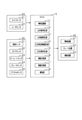
- FIG. 1 is a diagram showing a travel support system including a travel support device according to the first embodiment.
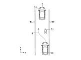
- FIG. 2 is a diagram illustrating a primary object.
- FIG. 3 is a diagram showing a steering avoidance route of the own vehicle for avoiding a collision with a primary target.
- FIG. 4 is a diagram illustrating a secondary determination region.
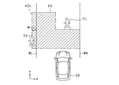
- FIG. 5 is a diagram showing a state in which a secondary object exists in the secondary determination area.
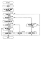
- FIG. 6 is a flowchart of the traveling support control according to the embodiment.
- FIG. 7 is a diagram illustrating the setting of the steering avoidance path R.
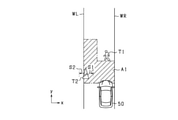
- FIG. 8 is a diagram illustrating the setting of the secondary determination area.
- FIG. 9 is a diagram illustrating determination of a secondary object in the secondary determination area.
- FIG. 10 is a diagram illustrating determination of a secondary object in the secondary determination area.
- FIG. 11 is a diagram illustrating a secondary determination region and a margin when the secondary target according to the modified example is the preceding vehicle.
- FIG. 12 is a diagram illustrating a secondary determination region and a margin when the secondary target according to the modified example is an oncoming vehicle.
- FIG. 13 is a diagram illustrating a secondary determination region and a margin when the secondary target according to the modified example is a pedestrian.
- FIG. 14 is a diagram illustrating a secondary determination region and a margin when the secondary object according to the modified example is a stationary object.
- FIG. 15 is a diagram for explaining the positional relationship between the secondary object and the secondary determination region according to the modified example.
- FIG. 16 is a diagram illustrating the setting of the secondary determination region according to the modified example.
- FIG. 17 is a diagram illustrating the setting of the secondary determination region according to the modified example.
- FIG. 1 shows a driving support system according to the present embodiment.
- the travel support system is mounted on the vehicle and includes an ECU 10, an object detection device 20, a travel state sensor 30, and a controlled device 40.
- the object detection device 20 includes a camera sensor 21 and a radar sensor 22.
- the camera sensor 21 and the radar sensor 22 are examples of object detection sensors that detect objects around the vehicle.
- the object detection sensor may include a sensor that transmits an ultrasonic sensor, a sensor that transmits an exploration wave such as a LIDAR (Light Detection and Ranger / Laser Imaging Detection and Ringing).
- LIDAR Light Detection and Ranger / Laser Imaging Detection and Ringing
- the camera sensor 21 may be a monocular camera such as a CCD camera, a CMOS image sensor, or a near-infrared camera, or may be a stereo camera. Only one camera sensor 21 may be installed in the own vehicle, or a plurality of camera sensors 21 may be installed.
- the camera sensor 21 is attached to, for example, a predetermined height in the center of the vehicle width direction of the vehicle, and captures an image of a region extending in a predetermined angle range toward the front of the vehicle from a bird's-eye view.
- the camera sensor 21 extracts feature points indicating the presence of an object in the captured image. Specifically, edge points are extracted based on the luminance information of the captured image, and the Hough transform is performed on the extracted edge points.
- the camera sensor 21 sequentially outputs the captured images to be sequentially captured to the ECU 10 as sensing information.
- the radar sensor 22 is, for example, a known millimeter wave radar whose transmission wave is a high frequency signal in the millimeter wave band. Only one radar sensor 22 may be installed in the own vehicle, or a plurality of radar sensors 22 may be installed in the own vehicle.
- the radar sensor 22 is provided at the front end of the vehicle, for example, and has a detection range in which an object can be detected in a region within a predetermined detection angle, and detects the position of the object within the detection range.
- the exploration wave is transmitted at a predetermined cycle, and the reflected wave is received by a plurality of antennas. The distance to the object can be calculated from the transmission time of the exploration wave and the reception time of the reflected wave.
- the relative velocity of the reflected wave reflected by the object is calculated from the frequency changed by the Doppler effect.
- the orientation of the object can be calculated from the phase difference of the reflected waves received by the plurality of antennas. If the position and orientation of the object can be calculated, the relative position of the object with respect to the own vehicle can be specified.
- the sensor that transmits the millimeter wave radar such as the radar sensor 22 and the exploration wave such as sonar and LIDAR sequentially feeds the ECU 10 the scanning result based on the received signal obtained when the reflected wave reflected by the obstacle is received. Output.
- the traveling state sensor 30 includes a vehicle speed sensor 31, a steering sensor 32, a yaw rate sensor 33, a brake sensor 34, and an accelerator sensor 35.
- the traveling state sensor 30 is a sensor mounted on a vehicle and capable of detecting traveling information (for example, vehicle speed, yaw rate, steering angle, etc.) which is various parameters indicating the traveling state of the own vehicle.
- the ECU 310 acquires the detection value of the traveling state sensor 30.
- the vehicle speed sensor 31 is provided on a rotating shaft that transmits power to the wheels of the own vehicle, and obtains the speed of the own vehicle based on the number of rotations of the rotating shaft.
- the steering sensor 32 is provided on the steering wheel and detects the direction of the steering operation by the driver and the operation amount thereof.
- the yaw rate sensor 33 outputs a yaw rate signal according to the change speed of the steering amount of the own vehicle to the ECU 10.
- the brake sensor 34 is provided on the brake pedal and detects whether or not the driver has operated the brake pedal and the amount of operation thereof.
- the accelerator sensor 35 is provided on the accelerator pedal, and detects whether or not the accelerator pedal is operated by the driver and the amount of operation thereof.
- the controlled device 40 includes an alarm device 41, a brake device 42, and a steering device 43.
- the alarm device 41, the brake device 42, and the steering device 43 are driven by a control command from the ECU 10.
- the alarm device 41 is, for example, a speaker or a display installed in the passenger compartment of the own vehicle.
- the alarm device 41 outputs an alarm sound, an alarm message, or the like based on a control command from the ECU 10 to notify the driver that there is a danger of collision with an object.
- the brake device 42 is a braking device that brakes the own vehicle.
- the ECU 10 does not have a brake assist function for enhancing and assisting the braking force by the driver's brake operation and a driver's brake operation as a brake function for avoiding a collision with an object or reducing collision damage. It has an automatic braking function that performs automatic braking in some cases.
- the brake device 42 performs brake control by these functions based on the control command from the ECU 10.
- the steering device 43 is a device for steering the own vehicle, and is controlled by a steering operation of the driver or a command from the ECU 10.
- the ECU 10 has a function of automatically controlling the steering device 43 for collision avoidance or lane change.
- the controlled device 40 may include a device controlled by the ECU 10 other than the above.
- a safety device or the like for ensuring the safety of the driver may be included.
- Specific examples of the safety device include a seatbelt device provided with a pretensioner mechanism for pulling in a seatbelt provided in each seat of the own vehicle.
- the ECU 10 includes an object recognition unit 11, a primary target determination unit 12, a primary avoidance determination unit 13, a secondary determination area setting unit 14, a secondary target determination unit 15, a steering support unit 16, and braking support.
- a unit 17 and a notification unit 18 are provided.
- the ECU 10 is provided with a CPU, ROM, RAM, I / O, etc., and the CPU realizes each of these functions by executing a program installed in the ROM. As a result, the ECU 10 creates and outputs a control command to the controlled device 40 based on the information acquired from the object detection device 20 and the running state sensor 30, and thereby executes the running support of the own vehicle. Functions as.
- the object recognition unit 11 acquires the detection information of the object from the camera sensor 21 and the radar sensor 22, and uses the feature points obtained from the camera sensor 21 and the position information of the object obtained from the radar sensor 22 at the position. Recognize the existence of an object. Further, the object recognition unit 11 associates a relative position and a relative speed with respect to the own vehicle for each object, and based on the associated relative position and the relative speed, the relative speed in a direction orthogonal to the traveling direction of the own vehicle. The lateral speed, which is, and the vertical speed, which is the relative speed with respect to the traveling direction of the own vehicle, are calculated.
- the object recognition unit 11 may be configured to recognize an object detected in the determination area set in a predetermined area around the own vehicle as a target object for collision avoidance. Further, the object recognition unit 11 is configured to be able to recognize the position and size of the road structure and the white line.
- the primary target determination unit 12 determines an object to be the primary target to avoid a collision with the own vehicle from a plurality of detection information acquired by the object recognition unit 11. Specifically, the object recognition unit 11 detects one or a plurality of objects existing in front of the traveling direction of the own vehicle, and among the detected objects, (1) the existence probability of the object is high, and (2). ) It is an object existing in the path of the own vehicle, and (3) the collision prediction time (TTC: Time to Collection), which is the time until the own vehicle and the object collide, is the minimum. Identify the primary target object that should avoid a collision with the vehicle.
- TTC Time to Collection
- the object existing in the path of the own vehicle may be specified by using a known technique, for example, based on the high probability of the own lane or the lateral position of the object.
- the object B is the object.
- the object B is specified as the primary target object.
- the primary target is a target object that is a target of collision avoidance in the current traveling path of the own vehicle.
- the type of the target object is, for example, a stationary object such as a vehicle, a bicycle, a pedestrian, a road cone, or a moving object.
- the vehicle 50 when the vehicle 50 travels in the positive direction of the y-axis in the traveling lane between the left white line WL and the right white line WR that are orthogonal to the y direction, the vehicle 50 is in front of the vehicle 50 (y).
- the primary avoidance determination unit 13 determines whether to avoid a collision with a primary target or execute control related to mitigation of collision damage. Specifically, based on the relative distance between the own vehicle and the primary target, the collision prediction time, which is the time until the own vehicle and the primary target collide, is calculated. Then, from the comparison between the collision prediction time and the operation timing, it is determined whether or not to operate the controlled device 40 such as the alarm device 41, the brake device 42, and the steering device 43 in order to avoid the collision.
- the operation timing is the timing at which the alarm device 41, the brake device 42, and the steering device 43 are desired to be operated, and may be set depending on the target to be operated.
- the primary avoidance determination unit 13 has 1 prior to executing collision avoidance with the primary target T1.
- the route R for avoiding steering of the own vehicle 50 for avoiding a collision with the next target T1 is set.
- the steering avoidance route R is a future travel route when the own vehicle 50 executes steering avoidance to the left.
- the steering avoidance route R is set in the traveling lane between the left white line WL and the right white line WR.
- the secondary determination area setting unit 14 sets a secondary determination area for determining an object to be a secondary target for avoiding a collision with the own vehicle in the steering avoidance route set by the primary avoidance determination unit 13. .
- the secondary target is a target object that is a target of collision avoidance in a future traveling route (steering avoidance route) when the own vehicle executes steering avoidance.
- the secondary determination area setting unit 14 sets the secondary determination area A1 around the steering avoidance path R.
- the secondary determination region A1 may be set to include the entire steering avoidance path R in the region, and may be set to a wider region than the steering avoidance path R.
- the secondary determination region A1 is set.
- the primary target T1 is selected to have a high probability of existence of an object, so that if the probability of existence of an object is low, it may be excluded from the primary target T1. be. Therefore, by setting the secondary determination area A1 between the own vehicle 50 and the primary target T1, the object excluded from the primary target T1 is placed between the own vehicle 50 and the primary target T1. Even if it exists, the object can be used as a target for determining whether or not control can be executed.
- the secondary target determination unit 15 determines an object to be a secondary target in the secondary determination region based on the detection information acquired by the object recognition unit 11. More specifically, based on the detection information acquired by the object recognition unit 11, it is determined whether or not an object to be a secondary target for avoiding a collision with the own vehicle exists in the secondary determination area. do. For example, as shown in FIG. 5, a pedestrian (T2) existing in the secondary determination region A1 collides with the own vehicle 50 when the own vehicle 50 travels on the steering avoidance route R. This pedestrian is recognized as the secondary target T2, and the secondary target determination unit 15 determines that the secondary target T2 exists.
- the secondary target determination unit 15 may be configured to set an existing area in which the secondary target exists based on the detection information. For example, a margin may be set around the secondary object, and an existing area including the margin may be set. Further, the secondary target determination unit 15 may be configured to determine that the secondary target exists when the existing region exists in the secondary determination region. By setting a margin around the secondary target and determining whether or not the existing area set to include the margin exists in the secondary judgment area, regardless of the type of the secondary target and the detection accuracy. However, the collision between the secondary target and the own vehicle can be avoided more reliably.
- the steering support unit 16 creates and outputs a control command for the steering device 43 when the primary avoidance determination unit 13 determines that the steering device 43 is to be operated to avoid a collision with the primary target. ..
- the primary target determination unit 12 determines that the primary target exists and the primary avoidance determination unit 13 determines that the steering device 43 is operated to avoid a collision with the primary target, steering is performed.
- the support unit 16 creates a control command for executing steering avoidance on condition that the secondary target determination unit 15 determines that the secondary target does not exist, and outputs the control command to the steering device 43.
- the steering support unit 16 is determined by the primary target determination unit 12 that the primary target T1 exists, and the primary avoidance determination unit 13 avoids collision with the primary target T1. Even when it is determined that the steering device 43 is to be operated, as shown in FIG. 5, when the secondary target determination unit 15 determines that the secondary target T2 exists, the vehicle 50 Suppress the creation of control commands to execute steering avoidance. Note that "suppressing the creation of a control command” may mean not creating a control command or suspending the creation of a control command.
- the determination of whether or not the predetermined condition is satisfied is further executed within the predetermined time, and based on the determination result, it is determined whether or not the control command is created. You may do it. Further, as another example, the steering control may be weakened so that steering avoidance is hardly executed.
- the braking support unit 17 creates a control command for operating the brake device 42 when the primary avoidance determination unit 13 determines that the brake device 42 is to be operated to avoid a collision with the primary target. Output to the brake device 42.
- the notification unit 18 creates a control command for operating the alarm device 41 when it is determined by the primary avoidance determination unit 13 to operate the alarm device 41 to warn of a collision with the primary target. Output to the alarm device 41.
- the traveling support control executed by the ECU 10 will be described with reference to the flowchart shown in FIG.
- the process shown in FIG. 6 is repeatedly executed at a predetermined cycle.
- step S101 the detection information of the objects around the own vehicle by the camera sensor 21 and the radar sensor 22 is acquired, and the process proceeds to step S102.
- step S102 object recognition is executed based on the object detection information acquired in step S101. Specifically, the distance between the own vehicle and the object, the lateral position of the object, the relative speed of the object with respect to the own vehicle, and the like are calculated. After that, the process proceeds to step S103.
- step S103 it is determined whether or not an object to be the primary target exists among the objects recognized in step S102. If, among the objects recognized in step S102, there is a target object to be subject to collision avoidance in the current traveling path of the own vehicle, that object is recognized as the primary target, and it is determined that the primary target exists.
- the process proceeds to step S104. For example, if the primary target T1 as shown in FIG. 2 exists, the process proceeds to step S104. If, among the objects recognized in step S102, there is no target object to be subject to collision avoidance in the current traveling path of the own vehicle, it is determined that the primary target does not exist, and the process ends.
- step S104 it is determined whether or not there is a steering avoidance route for the own vehicle to avoid a collision with the primary target. For example, when it is possible to set the steering avoidance path R as shown in FIG. 3, it is determined that the steering avoidance path exists. More specifically, there is a steering avoidance route R when there is a sufficient area between the left white line WL and the right white line WR for the vehicle 50 to avoid the primary target T1 and proceed. Then it is determined. For example, as shown in FIG. 7, when the own vehicle 50 can secure a predetermined lateral distance (distance in the x-axis direction) from the primary target T1 when the own vehicle 50 passes by the side of the position y1 of the primary target T1.
- the route R can be set as a region in which both ends thereof are the left end RL of the route and the right end RW of the route.
- the route R exists at the position y1 when the distance dxR between the position x1 at the left end of the primary target T1 and the position xR at the right end RW of the path on the side close to the primary target T1 can be secured.
- the distance between the position xWL of the left end RL of the route far from the primary target T1 and the position xWL of the left white line WL which is the white line near the left end RL of the route at the position y1 is defined as the distance dxL.
- Step S105 If it is determined that there is a steering avoidance route, the process proceeds to step S105. If it is determined that the steering avoidance route does not exist, the process proceeds to step S110. Steps S110 and S111 are processes for avoiding or reducing the collision between the primary target and the own vehicle by braking or warning instead of steering avoidance.
- the secondary determination area is set based on the steering avoidance route.
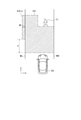
- the distances L1 to L5 are set as shown in FIG. do.
- the distance L1 is the distance (longitudinal distance) between the own vehicle 50 and the primary target T1 in the y-axis direction.
- the distance in the y-axis direction from the position y0 at the front end of the own vehicle 50 to the position y1 at the rear end of the primary target T1 can be set as the distance L1.
- the distance L2 is a vertical distance from the primary target T1 to the upper limit in the depth direction of the secondary determination region A1.
- the distance in the y-axis direction from the position y1 at the rear end of the primary target T1 to the upper limit position y2 in the depth direction of the secondary determination region A1 can be set as the distance L2.
- the distance L3 is the distance between the left white line WL and the right white line WR in the x-axis direction (horizontal distance).
- the distance between the position xWL of the left white line WL and the position xWR of the right white line WR in the x-axis direction can be set as the distance L3.
- the x-axis is orthogonal to the y-axis, and the vertical distance and the horizontal distance indicate distances in directions orthogonal to each other.
- the distance L4 is a lateral distance between the white line (left white line WL) located in the left direction, which is the steering direction of the own vehicle 50, and the primary target T1.
- the distance in the x-axis direction between the position xWL of the left white line WL and the position x1 of the left end of the primary target T1 can be set as the distance L4.
- the distance L5 is a region offset, which is a lateral distance between the primary target T1 and the secondary determination region A1 in the left direction, which is the steering direction of the own vehicle 50.
- the distance in the x-axis direction between the left end position x1 of the primary target T1 and the right end position x2 in the region deeper than y1 of the secondary determination region A1 can be set as the distance L5.
- the distances L1 to L5 can be set based on the distance between the own vehicle and the primary target calculated in step S102, the lateral position of the primary target, the relative speed of the primary target with respect to the own vehicle, the position of the white line, and the like. Then, the process proceeds to step S106.
- step S106 it is determined whether or not a secondary target exists in the secondary determination area set in step S105.
- margins S1 and S2 are set on both sides of the secondary target T2 in the lateral direction (x-axis direction).
- the margin S1 is a left margin which is the steering direction of the own vehicle 50
- the margin S2 is a right margin in the direction opposite to the steering direction of the own vehicle 50.
- the region including the margins S1 and S2 is recognized as the region where the secondary target T2 exists. Then, when a part or all of the recognized secondary target T2 exists in the secondary determination area A1, it is determined that the secondary target exists in the secondary determination area.
- step S106 when the right end of the margin S1 of the secondary target T2 is on the left side of the left white line WL, the existing region of the secondary target T2 including the margins S1 and S2 is the secondary determination region A1. It is determined that it does not exist inside. As a result, a negative determination is made in step S106, the process proceeds to step S109, and steering support is executed. Specifically, a control signal for executing steering avoidance is output to the steering device 43 according to the steering avoidance route set in step S104. After that, the process ends.
- step S106 when the right end of the margin S1 of the secondary target T2 is on the right side of the left white line WL, the existing region of the secondary target T2 including the margins S1 and S2 is the secondary determination region A1. It is determined that it exists inside. As a result, an affirmative determination is made in step S106, and the process proceeds to step S107.
- Steps S107 and S108 are processes for avoiding or reducing the collision between the primary target and the own vehicle by braking or warning instead of steering avoidance.
- step S107 it is determined whether or not to execute automatic braking or notification by an alarm for the primary target. Specifically, it is determined whether or not to operate the alarm device 41 and the brake device 42 in order to avoid the collision from the comparison between the collision prediction time and the operation timing. If an affirmative determination is made in step S107, the process ends after the alarm command to the alarm device 41 and the automatic braking command by the brake device 42 are executed in step S108. If a negative determination is made in step S107, the process ends as it is. Since the processes shown in steps S110 and S111 are the same as the processes shown in steps S107 and S108, the description thereof will be omitted.
- the ECU 10 determines that there is a primary target for avoiding a collision with the own vehicle as shown in step S103, and as shown in step S104, the primary target is determined.
- a secondary determination area is set based on the steering avoidance path as shown in S105.
- steering support is executed along the steering avoidance path.
- steps S106 to S108 when it is determined that the secondary object exists in the secondary determination region, the steering support is not executed, and the collision avoidance process by automatic braking or warning is executed.
- the ECU 10 is for avoiding a collision with the primary object when it is determined that the secondary object exists. Do not perform steering avoidance of the own vehicle. Therefore, by avoiding a collision with a primary object by automatic steering, it is possible to suppress an increase in the possibility of collision with another object different from the primary object existing in the avoidance path. Further, when steering avoidance is not executed, collision with the primary target can be avoided by means other than automatic steering.
- the secondary determination area setting unit 14 may be configured to change the size and installation position of the secondary determination area based on the type, speed, size, position, and the like of the secondary object.
- the secondary target determination unit 15 may be configured to change the margin of the secondary target and change the existing area based on the type, speed, size, position, etc. of the secondary target. ..
- the type, speed, and size of the secondary object can be acquired as detection information from the object detection device 20 by the object recognition unit 11.
- 11 to 14 show the secondary determination area and the margin when the secondary target is a preceding vehicle, an oncoming vehicle, a pedestrian, or a stationary object, respectively.
- the oncoming vehicle is a vehicle traveling in a direction opposite to the traveling direction of the own vehicle.
- the distance L2 is longer than when the secondary target T2 is the preceding vehicle, and the margins S1 and S2 are set. May be set to a large value.
- the distance L2 is 10 m and the margins S1 and S2 are 1 m, respectively, whereas in the case of the oncoming vehicle shown in FIG. 12, the distance L2 is.
- the secondary determination region A2 having a larger distance L2 than when the secondary target T2 is a preceding vehicle is set. Further, by setting the margins S1 and S2 to be large, the existing area is set to be large. As a result, it becomes easier to make an affirmative determination in step S106, and a collision between the secondary target T2 and the own vehicle 50 can be more reliably avoided.
- the secondary object T2 when the secondary object T2 is a road structure such as a road cone and has a low rank as a collision avoidance target, the secondary object T2 is a secondary object as shown in FIG.
- the margins S1 and S2 may be set larger than when the target T2 is an object having a high rank as a collision avoidance target such as a pedestrian. Specifically, for example, in the case of the pedestrian shown in FIG. 13, the margins S1 and S2 are 1 m each, whereas in the case of the oncoming vehicle shown in FIG. 14, the margins S1 and S2 are 1. It may be set to 3 m.
- the distance L2 in FIGS. 13 and 14 is set to the same 10 m.
- the existence probability is set according to the object type, and the size of the object may not be detected for an object with a low existence probability.
- an object such as a pedestrian whose existence probability is set to be high is detected by the size of the object such as the width (size in the x-axis direction), while the existence probability is high like a road structure.
- An object set to be low may be detected as a point, and the size of the object such as the width may not be detected.
- the margins S1 and S2 are made larger than the secondary target T2 having a high existence probability such as a pedestrian. The collision with the own vehicle 50 can be avoided more reliably.
- the margin S1L is provided for the secondary target T2L existing in the left direction, which is the direction of steering avoidance of the own vehicle 50, and the secondary target T2R existing in the right direction, which is the opposite direction of steering avoidance.
- S2L, S1R, S2R may be changed in size.
- the secondary target T2L existing in the direction of steering avoidance has a higher risk of colliding with the own vehicle 50 than the secondary target T2R existing in the direction opposite to the steering avoidance. It may be set larger than S2R.
- the margins S2L and S2R set on the opposite side of the secondary determination area A1 may be set smaller than the margins S1L and S1R set on the side of the secondary determination area A1, or may be set to zero. May be good.
- the secondary determination region A3 includes a region A3L that exceeds the left white line WL by the lateral length M corresponding to the margin set in the secondary target T2. For example, if the lateral length M is set to the same value as the margin S1L shown in FIG. 15, the existence of the secondary target is determined to the same extent as in FIG. 15 without setting the margin for the secondary target T2. It will be easier.
- the secondary determination area setting unit 14 may be configured to be set based on the type of the primary target T1 in the setting of the area offset L5, or may be detected when detecting an object around the own vehicle 50. It may be configured to be set based on accuracy, or it may be configured to be set based on a region in which the primary object T1 may exist after the collision prediction time TTC. For example, depending on the detection accuracy of an object, it may be possible to obtain a detection result in which a plurality of objects exist for one primary target T1. In such a case, the object detected at a position where the lateral distance from the primary target T1 is closer than the region offset L5 is treated as the same object as the primary target T1 to supplement the detection accuracy of the object.
- the secondary determination area can be appropriately set.
- the ECU 10 functions as a running support device that executes running support for avoiding a collision between the own vehicle and the object based on the detection information of an object existing around the own vehicle.
- the ECU 10 includes a primary target determination unit 12, a secondary determination area setting unit 14, a secondary target determination unit 15, and a steering support unit 16.
- the primary target determination unit 12 determines an object to be the primary target to avoid a collision with the own vehicle based on the detection information.
- the secondary determination area setting unit 14 is a secondary target object that should avoid a collision with the own vehicle in the steering avoidance route of the own vehicle for avoiding the collision with the primary target.
- the secondary judgment area for judging is set.
- the secondary target determination unit 15 determines an object to be a secondary target in the secondary determination region based on the detection information.
- the steering support unit 16 has a function of executing steering support of the own vehicle. Then, when the primary target determination unit 12 determines that the primary target exists and the secondary target determination unit 15 determines that the secondary target exists, the steering support unit 16 avoids steering of the own vehicle. Suppress. That is, even if the steering support unit 16 determines that the primary target exists by the primary target determination unit 12, if the secondary target determination unit 15 determines that the secondary target exists, the steering support unit 16 may determine that the secondary target exists. Suppresses steering avoidance of the own vehicle to avoid collision with the primary target. Therefore, as a result of avoiding a collision with a primary object by automatic steering of the steering support unit 16, it is possible to suppress an increase in the possibility of collision with another object different from the primary object existing in the avoidance path. can.
- the secondary determination area setting unit 14 may be configured to change the secondary determination area based on the type, speed, size, or position of the secondary target acquired as detection information.
- the size and installation position of the secondary judgment area should be changed appropriately. It is possible to more appropriately determine the possibility of collision between the secondary target and the own vehicle, and to execute appropriate driving support.
- the secondary target determination unit 15 may be configured to set an existing area in which the secondary target exists based on the detection information. Further, the secondary target determination unit 15 may be configured to determine that the secondary target exists when the existing region exists in the secondary determination region. By setting a margin around the secondary target and determining whether or not the existing area set to include the margin exists in the secondary judgment area, regardless of the type of the secondary target and the detection accuracy. However, the collision between the secondary target and the own vehicle can be avoided more reliably.
- the secondary target determination unit 15 may be configured to change the existing area based on the type, speed, size, or position of the secondary target acquired as detection information.
- the size and installation position of the existing area of the secondary target are appropriately changed. It is possible to more appropriately determine the possibility of collision between the secondary target and the own vehicle, and to execute appropriate driving support.
- the type of the secondary target is a vehicle (oncoming vehicle) traveling in a direction opposite to the traveling direction of the own vehicle
- the secondary target determination unit 15 has its own type of secondary target. It may be configured to have a larger existing area than a vehicle traveling in the same direction as the traveling direction of the vehicle (for example, a preceding vehicle).
- the steering support unit 16 is configured to suppress steering avoidance when it is determined that a secondary object exists in the secondary determination region in the steering avoidance determination.
- the vehicle may be configured to suppress steering avoidance of the own vehicle. .. If there is an oncoming vehicle in the direction of avoiding steering, the vehicle behaves as if the own vehicle and the oncoming vehicle approach each other, and collision avoidance by braking may be activated for the oncoming vehicle. Situations can be avoided.
- the distance L2 the distance in the y-axis direction from the position y1 at the rear end of the primary target T1 to the upper limit position y2 in the depth direction of the secondary determination region A1 is set.
- the distance L2 may be set according to the speed of the own vehicle. For example, as the speed of the own vehicle increases, the distance L2 can be set longer to set an appropriate determination area according to the speed of the own vehicle.
- the margins S1 and S2 are set for the existing region of the secondary target, but the margins S1 and S2 may be changed according to the traveling direction of the secondary target. Specifically, the margin on the traveling direction side of the secondary object may be changed to be larger than the margin on the opposite side of the traveling direction.
- the margins S1 and S2 may be changed by themselves, or the margins may be changed as a whole by adding a correction margin to the margins S1 and S2. Further, the margin may be changed according to the speed of progress.
- the margins S1 and S2 may be changed according to the distance between the own vehicle and the secondary target. Specifically, the margins S1 and S2 may be set small when the secondary target is close to the own vehicle and large when the secondary target is far from the own vehicle. Further, the margins S1 and S2 are set large when the secondary target exists behind the point where the vehicle is predicted to start steering avoidance, and the secondary target is on the front side from the point where the steering avoidance is started. If it exists, it may be set small. By setting in this way, it is possible to prevent the steering avoidance from being unnecessarily executed due to the secondary target existing before the steering avoidance is started. When margins are set for the own vehicle in the horizontal direction and the vertical direction, only the horizontal margins S1 and S2 may be changed.
- a region A3L having a lateral length M beyond the left white line WL is set in the secondary determination region A3.
- the present invention is not limited to this, and the region A3L may be added and a margin may be set in the secondary target T2.
- the region A3L not limited to the region A3L shown in FIG. 16 may be set as the region A3La beyond the left white line WL as shown in FIG.
- the region A3La beyond the left white line WL is set so as to avoid a distance Y in which the vehicle 50 travels straight from the current position until it starts to turn by steering.
- the controls and methods thereof described in the present disclosure are realized by a dedicated computer provided by configuring a processor and memory programmed to perform one or more functions embodied by a computer program. May be done.
- the controls and methods thereof described in the present disclosure may be implemented by a dedicated computer provided by configuring the processor with one or more dedicated hardware logic circuits.
- the control unit and method thereof described in the present disclosure may be a combination of a processor and memory programmed to perform one or more functions and a processor configured by one or more hardware logic circuits. It may be realized by one or more dedicated computers configured.
- the computer program may be stored in a computer-readable non-transitional tangible recording medium as an instruction executed by the computer.
Landscapes
- Engineering & Computer Science (AREA)
- Transportation (AREA)
- Mechanical Engineering (AREA)
- Automation & Control Theory (AREA)
- Chemical & Material Sciences (AREA)
- Combustion & Propulsion (AREA)
- Human Computer Interaction (AREA)
- Physics & Mathematics (AREA)
- General Physics & Mathematics (AREA)
- Traffic Control Systems (AREA)
- Control Of Driving Devices And Active Controlling Of Vehicle (AREA)
Priority Applications (3)
| Application Number | Priority Date | Filing Date | Title |
|---|---|---|---|
| JP2022544476A JP7413548B2 (ja) | 2020-08-25 | 2021-08-17 | 走行支援装置 |
| CN202180052377.XA CN115989165A (zh) | 2020-08-25 | 2021-08-17 | 行驶辅助装置 |
| US18/173,474 US12459570B2 (en) | 2020-08-25 | 2023-02-23 | Driving assistance device |
Applications Claiming Priority (2)
| Application Number | Priority Date | Filing Date | Title |
|---|---|---|---|
| JP2020-141756 | 2020-08-25 | ||
| JP2020141756 | 2020-08-25 |
Related Child Applications (1)
| Application Number | Title | Priority Date | Filing Date |
|---|---|---|---|
| US18/173,474 Continuation US12459570B2 (en) | 2020-08-25 | 2023-02-23 | Driving assistance device |
Publications (1)
| Publication Number | Publication Date |
|---|---|
| WO2022044885A1 true WO2022044885A1 (ja) | 2022-03-03 |
Family
ID=80354240
Family Applications (1)
| Application Number | Title | Priority Date | Filing Date |
|---|---|---|---|
| PCT/JP2021/030029 Ceased WO2022044885A1 (ja) | 2020-08-25 | 2021-08-17 | 走行支援装置 |
Country Status (4)
| Country | Link |
|---|---|
| US (1) | US12459570B2 (https=) |
| JP (1) | JP7413548B2 (https=) |
| CN (1) | CN115989165A (https=) |
| WO (1) | WO2022044885A1 (https=) |
Families Citing this family (2)
| Publication number | Priority date | Publication date | Assignee | Title |
|---|---|---|---|---|
| KR20230174784A (ko) * | 2022-06-21 | 2023-12-29 | 현대모비스 주식회사 | 주행 환경에 기반한 전방충돌방지 보조 방법 및 장치 |
| JP2025070189A (ja) * | 2023-10-19 | 2025-05-02 | 株式会社デンソー | 制御装置、制御方法、および制御プログラム |
Citations (2)
| Publication number | Priority date | Publication date | Assignee | Title |
|---|---|---|---|---|
| JP2019064336A (ja) * | 2017-09-29 | 2019-04-25 | トヨタ自動車株式会社 | 衝突回避支援装置 |
| JP2020100362A (ja) * | 2018-12-25 | 2020-07-02 | 株式会社デンソー | 運転支援装置 |
Family Cites Families (14)
| Publication number | Priority date | Publication date | Assignee | Title |
|---|---|---|---|---|
| US6405132B1 (en) * | 1997-10-22 | 2002-06-11 | Intelligent Technologies International, Inc. | Accident avoidance system |
| WO1997002167A1 (fr) * | 1995-07-04 | 1997-01-23 | Hiroyuki Minakami | Systeme de trafic/transport |
| AU2003225228A1 (en) * | 2002-05-03 | 2003-11-17 | Donnelly Corporation | Object detection system for vehicle |
| JP6308186B2 (ja) | 2015-08-28 | 2018-04-11 | トヨタ自動車株式会社 | 衝突回避支援装置 |
| US11320279B2 (en) * | 2016-12-02 | 2022-05-03 | Kubota Corporation | Travel route management system and travel route determination device |
| US11300976B2 (en) * | 2016-12-19 | 2022-04-12 | Kubota Corporation | Work vehicle automatic traveling system |
| EP3548845B1 (en) * | 2017-01-12 | 2021-10-13 | Mobileye Vision Technologies Ltd. | Navigation based on vehicle activity |
| JP6839006B2 (ja) * | 2017-03-21 | 2021-03-03 | 株式会社デンソー | 車両の運転支援装置及び運転支援方法 |
| US10372130B1 (en) * | 2017-05-19 | 2019-08-06 | Zoox, Inc. | Communicating reasons for vehicle actions |
| WO2018220828A1 (ja) * | 2017-06-02 | 2018-12-06 | 本田技研工業株式会社 | 車両制御システム、車両制御方法、およびプログラム |
| JP6765523B2 (ja) * | 2017-06-02 | 2020-10-07 | 本田技研工業株式会社 | 車両制御システム、車両制御方法、および車両制御プログラム |
| CN110709272B (zh) * | 2017-06-02 | 2022-10-25 | 本田技研工业株式会社 | 车辆控制系统、车辆控制方法及存储介质 |
| FR3087915B1 (fr) * | 2018-10-31 | 2021-09-17 | Thales Sa | Dispositif anticollision, systeme avionique de protection, procede d'anticollision et programme d'ordinateur associes |
| US11105921B2 (en) * | 2019-02-19 | 2021-08-31 | Honeywell International Inc. | Systems and methods for vehicle navigation |
-
2021
- 2021-08-17 JP JP2022544476A patent/JP7413548B2/ja active Active
- 2021-08-17 WO PCT/JP2021/030029 patent/WO2022044885A1/ja not_active Ceased
- 2021-08-17 CN CN202180052377.XA patent/CN115989165A/zh active Pending
-
2023
- 2023-02-23 US US18/173,474 patent/US12459570B2/en active Active
Patent Citations (2)
| Publication number | Priority date | Publication date | Assignee | Title |
|---|---|---|---|---|
| JP2019064336A (ja) * | 2017-09-29 | 2019-04-25 | トヨタ自動車株式会社 | 衝突回避支援装置 |
| JP2020100362A (ja) * | 2018-12-25 | 2020-07-02 | 株式会社デンソー | 運転支援装置 |
Also Published As
| Publication number | Publication date |
|---|---|
| JPWO2022044885A1 (https=) | 2022-03-03 |
| US12459570B2 (en) | 2025-11-04 |
| CN115989165A (zh) | 2023-04-18 |
| JP7413548B2 (ja) | 2024-01-15 |
| US20230192192A1 (en) | 2023-06-22 |
Similar Documents
| Publication | Publication Date | Title |
|---|---|---|
| JP6561584B2 (ja) | 車両制御装置、及び車両制御方法 | |
| JP6453695B2 (ja) | 運転支援装置、及び運転支援方法 | |
| CN108541325B (zh) | 驾驶辅助装置以及驾驶辅助方法 | |
| CN109204311B (zh) | 一种汽车速度控制方法和装置 | |
| JP4788778B2 (ja) | 逸脱警報装置、および逸脱警報プログラム | |
| WO2016159288A1 (ja) | 物標存在判定方法及び装置 | |
| US10787170B2 (en) | Vehicle control method and apparatus | |
| JP2016192166A (ja) | 車両制御装置、及び車両制御方法 | |
| CN108602494A (zh) | 车辆控制装置以及车辆控制方法 | |
| WO2016190103A1 (ja) | 車両制御装置及び車両制御方法 | |
| JP6432538B2 (ja) | 衝突予測装置 | |
| JP2016192167A (ja) | 車両制御装置、及び車両制御方法 | |
| WO2016186124A1 (ja) | 車両制御方法及び装置 | |
| JP2016037203A (ja) | 運転支援装置 | |
| US20230174093A1 (en) | Driving assistance device | |
| US12459570B2 (en) | Driving assistance device | |
| US12351166B2 (en) | Vehicle control device | |
| JP6311628B2 (ja) | 衝突回避制御装置 | |
| JP6720954B2 (ja) | 車両の物標検出装置 | |
| JP4872517B2 (ja) | 障害物認識装置 | |
| US12617395B2 (en) | Driving assistance apparatus | |
| JP7849662B2 (ja) | 運転支援装置 | |
| US20240416903A1 (en) | Driving assistance apparatus | |
| US20240425040A1 (en) | Driving assistance device | |
| JP7275000B2 (ja) | 制御装置 |
Legal Events
| Date | Code | Title | Description |
|---|---|---|---|
| 121 | Ep: the epo has been informed by wipo that ep was designated in this application |
Ref document number: 21861313 Country of ref document: EP Kind code of ref document: A1 |
|
| ENP | Entry into the national phase |
Ref document number: 2022544476 Country of ref document: JP Kind code of ref document: A |
|
| NENP | Non-entry into the national phase |
Ref country code: DE |
|
| 122 | Ep: pct application non-entry in european phase |
Ref document number: 21861313 Country of ref document: EP Kind code of ref document: A1 |