WO2022038898A1 - 接合体、保持装置、および、静電チャック - Google Patents
接合体、保持装置、および、静電チャック Download PDFInfo
- Publication number
- WO2022038898A1 WO2022038898A1 PCT/JP2021/024111 JP2021024111W WO2022038898A1 WO 2022038898 A1 WO2022038898 A1 WO 2022038898A1 JP 2021024111 W JP2021024111 W JP 2021024111W WO 2022038898 A1 WO2022038898 A1 WO 2022038898A1
- Authority
- WO
- WIPO (PCT)
- Prior art keywords
- hole
- metal layer
- metal
- tubular member
- electrostatic chuck
- Prior art date
Links
- 229910052751 metal Inorganic materials 0.000 claims abstract description 215
- 239000002184 metal Substances 0.000 claims abstract description 215
- 239000000463 material Substances 0.000 claims description 39
- 238000001179 sorption measurement Methods 0.000 claims description 4
- 239000000919 ceramic Substances 0.000 description 66
- 239000007789 gas Substances 0.000 description 36
- 239000012530 fluid Substances 0.000 description 24
- 239000001307 helium Substances 0.000 description 21
- 229910052734 helium Inorganic materials 0.000 description 21
- SWQJXJOGLNCZEY-UHFFFAOYSA-N helium atom Chemical compound [He] SWQJXJOGLNCZEY-UHFFFAOYSA-N 0.000 description 21
- 238000005219 brazing Methods 0.000 description 14
- 239000000835 fiber Substances 0.000 description 14
- 238000012986 modification Methods 0.000 description 12
- 230000004048 modification Effects 0.000 description 12
- 239000012634 fragment Substances 0.000 description 11
- 239000010936 titanium Substances 0.000 description 11
- RTAQQCXQSZGOHL-UHFFFAOYSA-N Titanium Chemical compound [Ti] RTAQQCXQSZGOHL-UHFFFAOYSA-N 0.000 description 8
- 230000035882 stress Effects 0.000 description 8
- 229910052719 titanium Inorganic materials 0.000 description 8
- 230000000052 comparative effect Effects 0.000 description 7
- 239000011888 foil Substances 0.000 description 7
- 230000008646 thermal stress Effects 0.000 description 5
- 238000011109 contamination Methods 0.000 description 4
- 239000011521 glass Substances 0.000 description 4
- 238000004519 manufacturing process Methods 0.000 description 4
- PXHVJJICTQNCMI-UHFFFAOYSA-N Nickel Chemical compound [Ni] PXHVJJICTQNCMI-UHFFFAOYSA-N 0.000 description 3
- 239000010949 copper Substances 0.000 description 3
- 238000005530 etching Methods 0.000 description 3
- 239000000945 filler Substances 0.000 description 3
- 239000000203 mixture Substances 0.000 description 3
- 239000003507 refrigerant Substances 0.000 description 3
- RYGMFSIKBFXOCR-UHFFFAOYSA-N Copper Chemical compound [Cu] RYGMFSIKBFXOCR-UHFFFAOYSA-N 0.000 description 2
- 239000004593 Epoxy Substances 0.000 description 2
- MCMNRKCIXSYSNV-UHFFFAOYSA-N Zirconium dioxide Chemical compound O=[Zr]=O MCMNRKCIXSYSNV-UHFFFAOYSA-N 0.000 description 2
- 239000000853 adhesive Substances 0.000 description 2
- 230000001070 adhesive effect Effects 0.000 description 2
- 229910052782 aluminium Inorganic materials 0.000 description 2
- XAGFODPZIPBFFR-UHFFFAOYSA-N aluminium Chemical compound [Al] XAGFODPZIPBFFR-UHFFFAOYSA-N 0.000 description 2
- PNEYBMLMFCGWSK-UHFFFAOYSA-N aluminium oxide Inorganic materials [O-2].[O-2].[O-2].[Al+3].[Al+3] PNEYBMLMFCGWSK-UHFFFAOYSA-N 0.000 description 2
- 238000005229 chemical vapour deposition Methods 0.000 description 2
- 229910052802 copper Inorganic materials 0.000 description 2
- 238000005304 joining Methods 0.000 description 2
- 238000000034 method Methods 0.000 description 2
- 238000005240 physical vapour deposition Methods 0.000 description 2
- 238000004549 pulsed laser deposition Methods 0.000 description 2
- 229920005989 resin Polymers 0.000 description 2
- 239000011347 resin Substances 0.000 description 2
- 239000010935 stainless steel Substances 0.000 description 2
- 229910001220 stainless steel Inorganic materials 0.000 description 2
- 239000004925 Acrylic resin Substances 0.000 description 1
- 229920000178 Acrylic resin Polymers 0.000 description 1
- 229910018072 Al 2 O 3 Inorganic materials 0.000 description 1
- 229910000838 Al alloy Inorganic materials 0.000 description 1
- PIGFYZPCRLYGLF-UHFFFAOYSA-N Aluminum nitride Chemical compound [Al]#N PIGFYZPCRLYGLF-UHFFFAOYSA-N 0.000 description 1
- 229910001369 Brass Inorganic materials 0.000 description 1
- YCKRFDGAMUMZLT-UHFFFAOYSA-N Fluorine atom Chemical compound [F] YCKRFDGAMUMZLT-UHFFFAOYSA-N 0.000 description 1
- ISWSIDIOOBJBQZ-UHFFFAOYSA-N Phenol Chemical compound OC1=CC=CC=C1 ISWSIDIOOBJBQZ-UHFFFAOYSA-N 0.000 description 1
- 229910052581 Si3N4 Inorganic materials 0.000 description 1
- BQCADISMDOOEFD-UHFFFAOYSA-N Silver Chemical compound [Ag] BQCADISMDOOEFD-UHFFFAOYSA-N 0.000 description 1
- 229910001069 Ti alloy Inorganic materials 0.000 description 1
- 229910045601 alloy Inorganic materials 0.000 description 1
- 239000000956 alloy Substances 0.000 description 1
- 239000010951 brass Substances 0.000 description 1
- 229910010293 ceramic material Inorganic materials 0.000 description 1
- 239000002131 composite material Substances 0.000 description 1
- 238000001816 cooling Methods 0.000 description 1
- PMHQVHHXPFUNSP-UHFFFAOYSA-M copper(1+);methylsulfanylmethane;bromide Chemical compound Br[Cu].CSC PMHQVHHXPFUNSP-UHFFFAOYSA-M 0.000 description 1
- 230000000694 effects Effects 0.000 description 1
- 238000005516 engineering process Methods 0.000 description 1
- 239000003822 epoxy resin Substances 0.000 description 1
- 238000001704 evaporation Methods 0.000 description 1
- 230000008020 evaporation Effects 0.000 description 1
- 229910052731 fluorine Inorganic materials 0.000 description 1
- 239000011737 fluorine Substances 0.000 description 1
- 238000010438 heat treatment Methods 0.000 description 1
- 239000007788 liquid Substances 0.000 description 1
- 238000003754 machining Methods 0.000 description 1
- 230000014759 maintenance of location Effects 0.000 description 1
- 150000002739 metals Chemical class 0.000 description 1
- 229910052759 nickel Inorganic materials 0.000 description 1
- 229920000647 polyepoxide Polymers 0.000 description 1
- 239000011148 porous material Substances 0.000 description 1
- 230000000717 retained effect Effects 0.000 description 1
- 239000004065 semiconductor Substances 0.000 description 1
- 238000000926 separation method Methods 0.000 description 1
- HBMJWWWQQXIZIP-UHFFFAOYSA-N silicon carbide Chemical compound [Si+]#[C-] HBMJWWWQQXIZIP-UHFFFAOYSA-N 0.000 description 1
- HQVNEWCFYHHQES-UHFFFAOYSA-N silicon nitride Chemical compound N12[Si]34N5[Si]62N3[Si]51N64 HQVNEWCFYHHQES-UHFFFAOYSA-N 0.000 description 1
- 229920002050 silicone resin Polymers 0.000 description 1
- 229910052709 silver Inorganic materials 0.000 description 1
- 239000004332 silver Substances 0.000 description 1
- 229910000679 solder Inorganic materials 0.000 description 1
- 229920005992 thermoplastic resin Polymers 0.000 description 1
- 229920001187 thermosetting polymer Polymers 0.000 description 1
- XLYOFNOQVPJJNP-UHFFFAOYSA-N water Substances O XLYOFNOQVPJJNP-UHFFFAOYSA-N 0.000 description 1
Images


Classifications
-
- C—CHEMISTRY; METALLURGY
- C04—CEMENTS; CONCRETE; ARTIFICIAL STONE; CERAMICS; REFRACTORIES
- C04B—LIME, MAGNESIA; SLAG; CEMENTS; COMPOSITIONS THEREOF, e.g. MORTARS, CONCRETE OR LIKE BUILDING MATERIALS; ARTIFICIAL STONE; CERAMICS; REFRACTORIES; TREATMENT OF NATURAL STONE
- C04B37/00—Joining burned ceramic articles with other burned ceramic articles or other articles by heating
- C04B37/02—Joining burned ceramic articles with other burned ceramic articles or other articles by heating with metallic articles
- C04B37/023—Joining burned ceramic articles with other burned ceramic articles or other articles by heating with metallic articles characterised by the interlayer used
- C04B37/026—Joining burned ceramic articles with other burned ceramic articles or other articles by heating with metallic articles characterised by the interlayer used consisting of metals or metal salts
-
- H—ELECTRICITY
- H01—ELECTRIC ELEMENTS
- H01L—SEMICONDUCTOR DEVICES NOT COVERED BY CLASS H10
- H01L21/00—Processes or apparatus adapted for the manufacture or treatment of semiconductor or solid state devices or of parts thereof
- H01L21/67—Apparatus specially adapted for handling semiconductor or electric solid state devices during manufacture or treatment thereof; Apparatus specially adapted for handling wafers during manufacture or treatment of semiconductor or electric solid state devices or components ; Apparatus not specifically provided for elsewhere
- H01L21/683—Apparatus specially adapted for handling semiconductor or electric solid state devices during manufacture or treatment thereof; Apparatus specially adapted for handling wafers during manufacture or treatment of semiconductor or electric solid state devices or components ; Apparatus not specifically provided for elsewhere for supporting or gripping
- H01L21/6831—Apparatus specially adapted for handling semiconductor or electric solid state devices during manufacture or treatment thereof; Apparatus specially adapted for handling wafers during manufacture or treatment of semiconductor or electric solid state devices or components ; Apparatus not specifically provided for elsewhere for supporting or gripping using electrostatic chucks
-
- C—CHEMISTRY; METALLURGY
- C04—CEMENTS; CONCRETE; ARTIFICIAL STONE; CERAMICS; REFRACTORIES
- C04B—LIME, MAGNESIA; SLAG; CEMENTS; COMPOSITIONS THEREOF, e.g. MORTARS, CONCRETE OR LIKE BUILDING MATERIALS; ARTIFICIAL STONE; CERAMICS; REFRACTORIES; TREATMENT OF NATURAL STONE
- C04B2237/00—Aspects relating to ceramic laminates or to joining of ceramic articles with other articles by heating
- C04B2237/02—Aspects relating to interlayers, e.g. used to join ceramic articles with other articles by heating
- C04B2237/12—Metallic interlayers
-
- C—CHEMISTRY; METALLURGY
- C04—CEMENTS; CONCRETE; ARTIFICIAL STONE; CERAMICS; REFRACTORIES
- C04B—LIME, MAGNESIA; SLAG; CEMENTS; COMPOSITIONS THEREOF, e.g. MORTARS, CONCRETE OR LIKE BUILDING MATERIALS; ARTIFICIAL STONE; CERAMICS; REFRACTORIES; TREATMENT OF NATURAL STONE
- C04B2237/00—Aspects relating to ceramic laminates or to joining of ceramic articles with other articles by heating
- C04B2237/30—Composition of layers of ceramic laminates or of ceramic or metallic articles to be joined by heating, e.g. Si substrates
- C04B2237/32—Ceramic
- C04B2237/34—Oxidic
- C04B2237/343—Alumina or aluminates
-
- C—CHEMISTRY; METALLURGY
- C04—CEMENTS; CONCRETE; ARTIFICIAL STONE; CERAMICS; REFRACTORIES
- C04B—LIME, MAGNESIA; SLAG; CEMENTS; COMPOSITIONS THEREOF, e.g. MORTARS, CONCRETE OR LIKE BUILDING MATERIALS; ARTIFICIAL STONE; CERAMICS; REFRACTORIES; TREATMENT OF NATURAL STONE
- C04B2237/00—Aspects relating to ceramic laminates or to joining of ceramic articles with other articles by heating
- C04B2237/30—Composition of layers of ceramic laminates or of ceramic or metallic articles to be joined by heating, e.g. Si substrates
- C04B2237/32—Ceramic
- C04B2237/36—Non-oxidic
- C04B2237/366—Aluminium nitride
-
- C—CHEMISTRY; METALLURGY
- C04—CEMENTS; CONCRETE; ARTIFICIAL STONE; CERAMICS; REFRACTORIES
- C04B—LIME, MAGNESIA; SLAG; CEMENTS; COMPOSITIONS THEREOF, e.g. MORTARS, CONCRETE OR LIKE BUILDING MATERIALS; ARTIFICIAL STONE; CERAMICS; REFRACTORIES; TREATMENT OF NATURAL STONE
- C04B2237/00—Aspects relating to ceramic laminates or to joining of ceramic articles with other articles by heating
- C04B2237/30—Composition of layers of ceramic laminates or of ceramic or metallic articles to be joined by heating, e.g. Si substrates
- C04B2237/40—Metallic
- C04B2237/403—Refractory metals
-
- C—CHEMISTRY; METALLURGY
- C04—CEMENTS; CONCRETE; ARTIFICIAL STONE; CERAMICS; REFRACTORIES
- C04B—LIME, MAGNESIA; SLAG; CEMENTS; COMPOSITIONS THEREOF, e.g. MORTARS, CONCRETE OR LIKE BUILDING MATERIALS; ARTIFICIAL STONE; CERAMICS; REFRACTORIES; TREATMENT OF NATURAL STONE
- C04B2237/00—Aspects relating to ceramic laminates or to joining of ceramic articles with other articles by heating
- C04B2237/50—Processing aspects relating to ceramic laminates or to the joining of ceramic articles with other articles by heating
- C04B2237/59—Aspects relating to the structure of the interlayer
- C04B2237/597—Aspects relating to the structure of the interlayer whereby the interlayer is continuous but porous, e.g. containing hollow or porous particles, macro- or micropores or cracks
-
- C—CHEMISTRY; METALLURGY
- C04—CEMENTS; CONCRETE; ARTIFICIAL STONE; CERAMICS; REFRACTORIES
- C04B—LIME, MAGNESIA; SLAG; CEMENTS; COMPOSITIONS THEREOF, e.g. MORTARS, CONCRETE OR LIKE BUILDING MATERIALS; ARTIFICIAL STONE; CERAMICS; REFRACTORIES; TREATMENT OF NATURAL STONE
- C04B2237/00—Aspects relating to ceramic laminates or to joining of ceramic articles with other articles by heating
- C04B2237/50—Processing aspects relating to ceramic laminates or to the joining of ceramic articles with other articles by heating
- C04B2237/62—Forming laminates or joined articles comprising holes, channels or other types of openings
-
- C—CHEMISTRY; METALLURGY
- C04—CEMENTS; CONCRETE; ARTIFICIAL STONE; CERAMICS; REFRACTORIES
- C04B—LIME, MAGNESIA; SLAG; CEMENTS; COMPOSITIONS THEREOF, e.g. MORTARS, CONCRETE OR LIKE BUILDING MATERIALS; ARTIFICIAL STONE; CERAMICS; REFRACTORIES; TREATMENT OF NATURAL STONE
- C04B2237/00—Aspects relating to ceramic laminates or to joining of ceramic articles with other articles by heating
- C04B2237/50—Processing aspects relating to ceramic laminates or to the joining of ceramic articles with other articles by heating
- C04B2237/76—Forming laminates or joined articles comprising at least one member in the form other than a sheet or disc, e.g. two tubes or a tube and a sheet or disc
- C04B2237/765—Forming laminates or joined articles comprising at least one member in the form other than a sheet or disc, e.g. two tubes or a tube and a sheet or disc at least one member being a tube
Definitions
- the present invention relates to a bonded body, a holding device, and an electrostatic chuck.
- a holding device for holding a wafer includes a ceramic member having a mounting surface on which the wafer is placed, a metal member for cooling the wafer, and a joint portion for joining the ceramic member and the metal member. It has a bonded body (for example, Patent Document 1).
- a metal layer may be placed at the joint of the joint in order to relieve the stress due to the difference in thermal expansion between the ceramic member and the metal member.
- the fluid in the through hole leaks from the inside of the through hole to the inside of the metal layer, or the fluid outside the holding device penetrates through the hole in the metal layer. There was a risk of flowing into the hole. In addition, debris from the metal layer may fall into the through hole.
- the present invention has been made to solve at least a part of the above-mentioned problems, and can be realized as the following forms.
- a bonded body in which the first member and the second member are joined via a joint portion including a metal layer having a plurality of holes communicating with each other.
- a metal layer having a plurality of holes communicating with each other.
- through holes communicating with each other are formed in the first member and the metal layer, respectively, and between the inside of the through holes formed in the metal layer and the inside of the metal layer, Cylindrical members are arranged.
- the metal layer included in the joint portion has a plurality of holes communicating with each other, and the metal layer is formed with through holes communicating with the through holes formed in the first member.
- a cylindrical member is arranged between the inside of the through hole of the metal layer and the inside of the metal layer.
- the second member may be formed with a through hole communicating with the through hole formed in the first member and the metal layer, respectively.
- the through holes formed in the first member and the metal layer, respectively, and the through holes formed in the second member communicate with each other.
- the tubular member suppresses the leakage of the fluid in the through hole to the metal layer and the inflow of the fluid inside the metal layer into the through hole.
- the change in the flow rate of the fluid flowing through the through hole of the second member with respect to the flow rate of the fluid flowing through the through hole of the second member becomes small. As a result, the fluid can be stably supplied from the first member side to the second member side or from the second member side to the first member side with the joint body interposed therebetween.
- one end of the tubular member is arranged inside a through hole formed in the first member, and the other end of the tubular member is the first. It may be arranged inside the through hole formed in the two members. According to this configuration, one end of the tubular member is arranged inside the through hole of the first member, and the other end is arranged inside the through hole of the second member.
- a bellows portion may be formed on the outer periphery of the tubular member in the circumferential direction.
- a bellows portion is formed on the outer periphery of the tubular member over the circumferential direction.
- the tubular member may be formed of the same material as the metal layer.
- the tubular member is made of the same material as the metal layer.
- the joint portion is formed of two types of materials, that is, the material of the tubular member and the metal layer, and the material of the brazing material. Therefore, the tubular member, the metal layer, and the brazing material are made of different materials. Compared to the case where it is formed, the composition of the joint is uniform regardless of the site. Therefore, the difference in thermal stress between the portions is less likely to occur at the joint portion, and the breakage of the joint body can be further suppressed.
- the cross section perpendicular to the axial direction of the tubular member may be circular.
- the tubular member is formed so that the cross section perpendicular to the axial direction has a circular shape.
- the tubular member is less likely to be deformed by the force acting from the direction intersecting the axis, so that the fluid moves between the through hole and the metal layer and the metal layer debris falls into the through hole. It can be suppressed.
- a holding device includes the above-mentioned joint body, and the second member includes a mounting surface on which a holding object is placed.
- the through holes formed in the first member and the metal layer and the through holes of the second member communicate with each other, the change in the flow rate of the fluid flowing through these through holes is suppressed. Therefore, the fluid can be stably supplied between the holding object and the mounting surface. Further, since the falling of the metal layer debris into the through hole is suppressed, it is possible to suppress the contamination of the object to be retained by the metal layer debris. As a result, the yield of the product can be improved.
- an electrostatic chuck includes the above-mentioned holding device, and the second member has an electrostatic adsorption electrode inside.
- the joint is formed with through holes for supplying fluid to the mounting surface.
- the tubular member arranged between the inside of the through hole of the metal layer and the inside of the metal layer can suppress the blockage of the through hole due to the leakage of the bonding material to the through hole. can.
- the falling of the metal layer debris into the through hole is suppressed, so that contamination by the metal layer debris can be suppressed. Therefore, it is possible to improve the yield of products manufactured by using the electrostatic chuck.
- the present invention can be realized in various aspects, for example, in the form of a device including a bonded body, a method for manufacturing a bonded body and a holding device, and the like.
- FIG. 1 is a perspective view showing the appearance of the electrostatic chuck 1 of the first embodiment.
- FIG. 2 is an overall cross-sectional view of the electrostatic chuck 1.
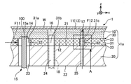
- FIG. 3 is a partial cross-sectional view of the electrostatic chuck 1.
- the electrostatic chuck 1 of the first embodiment is a holding device that holds the wafer W by adsorbing it by electrostatic attraction, and is provided in, for example, an etching device.
- the electrostatic chuck 1 includes a ceramic member 10, an electrode terminal 15, a lift pin 18, a metal member 20, and a joint portion 30. In the electrostatic chuck 1, the ceramic member 10, the joint portion 30, and the metal member 20 are laminated in this order in the z-axis direction (vertical direction).
- the joint body 1a composed of the ceramic member 10, the joint portion 30, and the metal member 20 is a substantially circular columnar body.
- the ceramic member 10 corresponds to the "second member” in the claims.
- the metal member 20 corresponds to the "first member” in the claims.
- Wafer W corresponds to the "retention target” in the claims.
- the ceramic member 10 is a plate-shaped member having a substantially circular shape, and is made of alumina (Al 2 O 3 ).
- the diameter of the ceramic member 10 is, for example, about 50 mm to 500 mm (usually about 200 mm to 350 mm), and the thickness of the ceramic member 10 is, for example, about 1 mm to 10 mm.
- the ceramic member 10 has a pair of main surfaces 11 and 12. A mounting surface 13 on which the wafer W is mounted is formed on the main surface 11 of one of the pair of main surfaces 11 and 12. The wafer W mounted on the mounting surface 13 is attracted to the mounting surface 13 by the electrostatic attraction generated by the electrostatic adsorption electrode 100 (see FIGS. 2 and 3) arranged inside the ceramic member 10. It is fixed.
- a recess 14 is formed on the other main surface 12.
- an end portion 15a of an electrode terminal 15 that supplies electric power from a power source (not shown) to the electrostatic adsorption electrode 100 is arranged.
- the ceramic forming the ceramic member 10 is aluminum nitride (AlN), zirconia (ZrO 2 ), silicon nitride (Si 3 N 4 ), silicon carbide (SiC), itria (Y 2 O 3 ), or the like. good.
- the through hole 16 penetrates the ceramic member 10 in the z-axis direction, and the lift pin 18 is inserted.
- the through hole 17 is a flow path through which the helium gas supplied between the mounting surface 13 and the wafer W flows when the wafer W is mounted on the mounting surface 13.
- the metal member 20 is a substantially circular planar plate-shaped member made of stainless steel, and has a pair of main surfaces 21 and 22.
- the diameter of the metal member 20 is, for example, about 220 mm to 550 mm (usually 220 mm to 350 mm), and the thickness of the metal member 20 is, for example, about 20 mm to 40 mm.
- a refrigerant flow path 200 is formed inside the metal member 20 (see FIG. 2). When a refrigerant such as a fluorine-based inert liquid or water flows through the refrigerant flow path 200, the ceramic member 10 is cooled through the joint portion 30, and the wafer W placed on the ceramic member 10 is cooled.
- the type of metal forming the metal member 20 may be copper (Cu), aluminum (Al), aluminum alloy, titanium (Ti), titanium alloy, or the like.
- Three through holes 23, 24, and 25 are formed in the metal member 20. As shown in FIG. 3, each of the three through holes 23, 24, and 25 penetrates the ceramic member 10 in the z-axis direction.
- the electrode terminal 15 is inserted through the through hole 23.
- the lift pin 18 is inserted into the through hole 24.
- the through hole 25 is a flow path through which the helium gas supplied between the mounting surface 13 and the wafer W flows when the wafer W is mounted on the mounting surface 13.
- the joint portion 30 includes a metal layer 31, a tubular member 32, and a brazing material 33, and joins the ceramic member 10 and the metal member 20.
- the metal layer 31 is a plate-shaped member having a substantially circular planar shape, and is a porous body having a plurality of holes communicating with each other.
- the metal layer 31 is a felt formed of metal fibers containing titanium (Ti), and is arranged between the ceramic member 10 and the metal member 20.
- the metal layer 31 is not limited to felt formed from metal fibers, and may be a porous material or a mesh structural material. Further, the metal forming the metal layer 31 may be formed of nickel (Ni), aluminum, copper, brass, alloys thereof, stainless steel, or the like.
- the through hole 31a communicates the recess 14 of the ceramic member 10 with the through hole 23 of the metal member 20.
- the through hole 31b communicates the through hole 16 of the ceramic member 10 and the through hole 24 of the metal member 20.
- the through hole 31c communicates the through hole 17 of the ceramic member 10 and the through hole 25 of the metal member 20. That is, through holes 23, 25, 31a, and 31c that communicate with each other are formed in the metal member 20 and the metal layer 31, respectively, and the through holes formed in the metal member 20 and the metal layer 31 are formed in the ceramic member 10, respectively.
- a through hole 17 communicating with the holes 25 and 31c is formed.
- the tubular member 32 is a cylindrical member, which is a member which is open vertically and whose side surface is sealed. As shown in FIG. 3, the tubular member 32 is arranged inside each of the through hole 31a and the through hole 31c.
- the tubular member 32 is formed of a metal containing titanium, which is the same material as the metal layer 31, and is suitable for use in a high temperature environment.
- the tubular member 32 has a height of 0.5 mm to 2.0 mm and an outer wall thickness of 0.01 mm to 0.15 mm.
- FIG. 4 is a first view illustrating the tubular member 32, and is an enlarged view of part A in FIG.
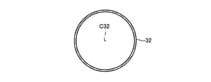
- FIG. 5 is a second view illustrating the tubular member 32, and is a cross-sectional view perpendicular to the axis C32 of the tubular member 32.
- one end 32a of the two ends 32a and 32b is in contact with one main surface 21 of the metal member 20, and the other end 32b is the other of the ceramic member 10. Is in contact with the main surface 12 of the.
- one end 32a and one main surface 21 of the metal member 20 are joined by a brazing material (not shown), and the other end 32b and the other main surface 12 of the ceramic member 10 are not shown. It is joined by a non-wax material.
- the cross section of the tubular member 32 perpendicular to the axis C32 direction is circular (see FIG. 5).
- the tubular member 32 arranged inside the through hole 31a regulates the movement of fluid between the inside of the through hole 31a and the inside of the metal layer 31.
- the tubular member 32 arranged inside the through hole 31c regulates the movement of the fluid between the inside of the through hole 31c and the inside of the metal layer 31.
- the through hole 25 of the metal member 20, the through hole 31c of the metal layer 31, and the helium gas flowing through the through hole 17 of the ceramic member 10 are suppressed from leaking into the inside of the metal layer 31, and the metal layer is prevented from leaking. Fragments of the metal fiber of 31 are suppressed from falling into the through hole 31c.
- the brazing filler metal 33 is a silver (Ag) -based brazing filler metal, and while entering the plurality of holes of the metal layer 31, the other main surface 12 of the ceramic member 10 and the one main surface 21 of the metal member 20 respectively. It is joined to.
- the brazing material 33 is a brazing material containing titanium (Ti), a filler material such as solder, an adhesive material such as a silicone resin, an acrylic resin, an epoxy resin, or an inorganic adhesive material such as glass paste. There may be.
- a metal foil hereinafter, “” “Metal leaf on the metal member side”
- the metal layer 31 on which the through holes 31a, 31b, and 31c are formed is arranged on the metal foil on the metal member side, and the tubular member 32 is inserted into each of the through holes 31a, 31c.
- another metal foil hereinafter referred to as "metal foil on the ceramic member side" to be the brazing material 33 is arranged on the side of the metal layer 31 opposite to the metal member 20.
- the ceramic member 10 is arranged on the metal foil on the ceramic member side, the ceramic member 10 and the metal layer 31 are joined by using the metal foil on the ceramic member side, and the metal member 20 and the metal member 20 are joined by using the metal foil on the metal member side. It is joined to the metal layer 31. As a result, the bonded body 1a is completed.
- the electrostatic chuck 1 is completed by assembling the electrode terminal 15 and the lift pin 18 to the completed joint body 1a.
- FIG. 6 is a cross-sectional view of the electrostatic chuck 5 of the comparative example.
- the tubular member 32 on the electrostatic chuck 1 of the present embodiment will be described in comparison with the electrostatic chuck 5 of the comparative example.
- the tubular member is not arranged inside the through holes 31a and 31c of the joint portion 30.
- the processing gas stays around the electrostatic chuck 5.
- This processing gas may flow into the through hole 31a through a plurality of holes formed inside the metal layer 31 (see the dotted arrow F01 in FIG. 6). Further, with the inflow of the processing gas at this time, fragments of the metal fibers of the metal layer 31 may fall into the through hole 31a.
- the through hole 25 of the metal member 20, the through hole 31c of the joint portion 30, and the ceramic member 10 are between the mounting surface 13 and the wafer W.
- Helium gas is supplied through the through hole 17 of the above.
- the helium gas passing through the inside of the through hole 31c of the joint portion 30 leaks from the through hole 31c to the plurality of holes of the metal layer 31 (see the dotted arrow F02 in FIG. 6).
- the flow rate of helium gas flowing through the through hole 31c may decrease, and it is difficult to stably supply helium gas between the mounting surface 13 and the wafer W.
- the residual gas in the joint portion 30 may flow into the through hole 31c, and the inflow of the residual gas into the through hole 31c may contaminate the wafer W. Further, with the inflow of the residual gas, the fragments of the metal fibers of the metal layer 31 fall into the through hole 31c and move to the mounting surface 13 together with the helium gas, and adhere to the wafer W to contaminate the wafer W. There is a risk.
- the tubular member 32 is arranged inside the through hole 31a of the joint portion 30 (see FIG. 3).
- the processing gas staying around the electrostatic chuck 1 is blocked by the tubular member 32 arranged inside the through hole 31a, so that it is difficult for the processing gas to flow into the through holes 23, 31a and the recess 14 (FIG. 3).
- the fragments of the metal fibers of the metal layer 31 are also suppressed from entering the through holes 23, 31a and the recess 14 by the tubular member 32.
- the tubular member 32 is arranged inside the through hole 31c of the joint portion 30 (see FIG. 3).
- the helium gas flowing through the through hole 31c of the joint portion 30 does not leak into the inside of the metal layer 31 in the through hole 31c, and is stably supplied between the mounting surface 13 and the wafer W ( (See the dotted arrow F12 in FIG. 3), the helium gas atmosphere between the mounting surface 13 and the wafer W can be stabilized.
- the residual gas in the joint portion 30 is suppressed from flowing into the through hole 31c, contamination of the wafer W is suppressed.
- the debris of the metal fiber of the metal layer 31 is suppressed from falling into the through hole 31c with the inflow of the residual gas of the joint portion 30, the debris is suppressed from contaminating the wafer W.
- the metal layer 31 included in the joint portion 30 has a plurality of holes communicating with each other, and the metal layer 31 is formed on the metal member 20.
- Through holes 31a and 31c communicating with the through holes 23 and 25 are formed.
- a tubular member 32 that regulates the movement of gas between the inside of each of the through holes 31a and 31c and the inside of the metal layer 31 is arranged inside each of the through holes 31a and 31c of the metal layer 31 arranged. ..
- the tubular member 32 arranged inside the through hole 31a suppresses the inflow of the processing gas of the wafer W into the through hole 31a, and the metal fiber fragments of the metal layer 31 fall into the through hole 31a. Can be suppressed.
- tubular member 32 arranged inside the through hole 31c is a through hole for the metal fiber fragments of the metal layer 31 while suppressing the leakage of helium gas flowing through the through hole 31c into the metal layer 31. It is possible to suppress the fall to 31a.
- the through holes 25 and 31c formed in the metal member 20 and the metal layer 31, respectively, and the through holes 17 formed in the ceramic member 10 communicate with each other.
- the through hole 31c formed in the metal layer 31 helium gas flowing through the through hole 31c is suppressed from leaking to the metal layer 31, and fluid inside the metal layer 31 is suppressed from flowing into the inside of the through hole 31c. Therefore, the change in the flow rate of the helium gas flowing through the through hole 17 of the ceramic member 10 with respect to the flow rate of the helium gas flowing through the through hole 25 of the metal member 20 becomes small.
- the helium gas can be stably supplied from the metal member 20 side to the ceramic member 10 side across the bonded body 1a, so that the helium gas can be stably supplied between the wafer W and the mounting surface 13. Can be supplied.
- the tubular member 32 is formed of the same material as the metal layer 31.
- the joint portion 30 is formed of two types of materials, the material of the metal layer 31 and the tubular member 32, and the material of the brazing material 33, so that the brazing material, the metal layer, and the tubular member are separate.
- the composition of the joint portion 30 becomes uniform regardless of the site. Therefore, the difference in thermal stress between the portions is less likely to occur in the joint portion 30, and damage to the joint body 1a can be suppressed.
- the tubular member 32 is formed so that the cross section perpendicular to the axis C32 direction has a circular shape. As a result, the tubular member 32 is less likely to be deformed by the force acting from the direction intersecting the axis C32, so that the fluid moves between the through holes 31a and 31c and the metal layer 31 and the through holes 31a and 31c It is possible to further suppress the falling of the debris of the metal layer 31 to the metal layer 31.
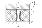
- FIG. 7 is a cross-sectional view of the electrostatic chuck 2 of the second embodiment.
- the electrostatic chuck 2 of the second embodiment has a different shape of the tubular member as compared with the electrostatic chuck 1 of the first embodiment (FIG. 3).
- the electrostatic chuck 2 of the present embodiment includes a ceramic member 10, an electrode terminal 15, a lift pin 18, a metal member 20, and a joint portion 40.
- the joint portion 40 joins the ceramic member 10 and the metal member 20, and includes a metal layer 31, a tubular member 42, and a brazing material 33.
- the joint body 2a composed of the ceramic member 10, the joint portion 40, and the metal member 20 is a substantially circular columnar body.
- the tubular member 42 is a member having a substantially cylindrical shape, and is a member that is open up and down and whose side surface is sealed. As shown in FIG. 7, the tubular member 42 is arranged inside each of the through hole 31a and the through hole 31c.
- the tubular member 42 arranged inside the through hole 31a suppresses the inflow of the processing gas of the wafer W into the through hole 31a and suppresses the falling of the metal fiber fragments of the metal layer 31 into the through hole 31a. do.
- the tubular member 42 arranged inside the through hole 31c suppresses the leakage of helium gas flowing through the through hole 31c into the metal layer 31, while suppressing the leakage of helium gas flowing through the through hole 31c into the through hole 31a of the metal fiber fragments of the metal layer 31. Suppress the fall to.
- FIG. 8 is an enlarged cross-sectional view of the electrostatic chuck 2 and is an enlarged view of part B in FIG.
- the tubular member 42 has two ends 42a, 42b and a bellows portion 42c connecting the two ends 42a, 42b.
- One end portion 42a is located on the minus side of the tubular member 42 in the z-axis direction and comes into contact with one main surface 21 of the metal member 20.
- the other end portion 42b is located on the positive side of the tubular member 42 in the z-axis direction and comes into contact with the other main surface 12 of the ceramic member 10.
- the bellows portion 42c is formed on the outer periphery of the tubular member 42 over the circumferential direction. The bellows portion 42c is deformed according to the relationship between the position of one end portion 42a and the position of the other end portion 42b.
- a bellows portion 42c is formed on the outer periphery of the tubular member 42 in the circumferential direction.
- FIG. 9 is a partial cross-sectional view of the electrostatic chuck 3 of the third embodiment.
- the electrostatic chuck 3 of the third embodiment is different from the electrostatic chuck 1 of the first embodiment (FIG. 3) in the position of the end portion of the tubular member.
- the electrostatic chuck 3 of the present embodiment includes a ceramic member 10, an electrode terminal 15, a lift pin 18, a metal member 20, and a joint portion 50.
- the joint portion 50 joins the ceramic member 10 and the metal member 20, and includes a metal layer 31, tubular members 52 and 53, and a brazing material 33.
- the joint body 3a composed of the ceramic member 10, the joint portion 50, and the metal member 20 is a substantially circular columnar body.
- the tubular member 52 is a cylindrical member, which is a member which is open vertically and whose side surface is sealed, and is arranged inside the through hole 31a of the metal layer 31. As shown in FIG. 9, the tubular member 52 has one end 52a of the two ends 52a and 52b arranged inside the through hole 23 of the metal member 20. The other end 52b is in contact with the other main surface 12 of the ceramic member 10. As a result, it becomes difficult to form a gap between the metal member 20 and the tubular member 52, so that the inflow of the processing gas of the wafer W into the through hole 31a is suppressed, and the metal fiber fragments of the metal layer 31 penetrate. The fall into the hole 31a is suppressed.
- the other end portion 52b of the tubular member 52 may be arranged in a groove formed in the other main surface 12 of the ceramic member 10.
- FIG. 10 is an enlarged cross-sectional view of the electrostatic chuck 3 and is an enlarged view of a portion C in FIG.
- the tubular member 53 is a cylindrical member, which is a member which is open vertically and whose side surfaces are sealed, and is arranged inside the through hole 31c of the metal layer 31.
- one end 53a of the two ends 53a and 53b is arranged inside the through hole 25 of the metal member 20.
- the other end 53b is arranged inside the through hole 17 of the ceramic member 10.
- one end 52a of the tubular member 52 is arranged inside the through hole 23 of the metal member 20.
- One end 53a of the tubular member 53 is arranged inside the through hole 25 of the metal member 20, and the other end 53b is arranged inside the through hole 17 of the ceramic member 10.
- the tubular members 52 and 53 are affected by the thermal stress generated inside the electrostatic chuck 3 when the ceramic member 10 and the metal member 20 are joined by the joint portion 50 or when the electrostatic chuck 3 is used at a high temperature. Separation from the ceramic member 10 and the metal member 20 is suppressed. Therefore, it is possible to further restrict the movement of the fluid between the inside of the through hole 31c and the inside of the metal layer 31, and further suppress the debris of the metal layer 31 from falling into the through hole 31c.
- the "joint” includes a ceramic member 10 and a metal member 20.
- the combination of members constituting the "joint body” is not limited to this.
- it may be a bonded body in which ceramic members are bonded to each other, or a bonded body in which metal members are bonded to each other.
- it may be formed of materials other than ceramics and metals.
- it may be formed of a resin such as glass, glass epoxy, a thermoplastic resin and a thermosetting resin, paper phenol, paper epoxy, a glass composite, a metal member having an insulating member thereof formed on the surface, or the like.
- the ceramic member 10 has a recess 14 communicating with the through hole 31a of the joint portion 30 and a through hole 17 as a "through hole of the second member" communicating with the through hole 31c.
- the "second member" may be formed with either a recess or a "through hole” that communicates with the through hole of the joint. Further, the recess and the through hole may not be formed, or a plurality of through holes may be formed.
- the tubular member is formed of a metal containing titanium, which is the same material as the metal layer.
- the material forming the tubular member and the material forming the metal layer may be different, and the material is not limited to the metal containing titanium.
- a metal other than titanium may be used, or a ceramic material such as alumina or aluminum nitride may be used.
- it is desirable that the tubular member is a dense body.
- the tubular member has a circular cross section perpendicular to the axial direction of the tubular member.
- the cross section of the tubular member perpendicular to the axial direction does not have to be circular.
- the electrostatic chuck is provided in the etching apparatus.
- the field of application of the electrostatic chuck is not limited to this.
- it may be an electrostatic chuck provided with a heater for heating the wafer.
- the electrostatic chuck includes a heater, the electrostatic chuck is used in a high temperature environment. Therefore, it is desirable that the material forming the tubular member is made of a metal having a high heat resistant temperature.
- the electrostatic chuck may be used for fixing, straightening, transporting, and the like of a wafer in a semiconductor manufacturing apparatus.
- the device including the "holding device” including the bonded body is not limited to the electrostatic chuck, and for example, a CVD (Chemical Vapor Deposition) device, a PVD (Physical Vapor Deposition) device, a PLD (Pulsed Laser Deposition) device, and the like. It may be used as a heater for a vacuum device, a susceptor, or a mounting table. Therefore, the force for holding the object to be held is not limited to the electrostatic attraction.
- CVD Chemical Vapor Deposition
- PVD Physical Vapor Deposition
- PLD Pulsed Laser Deposition
- At least one of the space between the ceramic member and the joint and the metal member and the joint may be provided with another layer such as a metal layer.
- the other layer may be, for example, a layer formed by evaporation of titanium in the brazing material forming the joint, a metallized layer formed in advance, or the like.
- the joints 1a, 2a, and 3a of the ceramic member 10, the joints 30, 40, and 50, and the metal member 20 are assumed to be substantially circular columnar bodies.
- the shape of the "joint” is not limited to this. For example, it may have a rectangular shape, a polygonal shape, or the like.
- one end 52a of the tubular member 52 arranged around the electrode terminal 15 is arranged inside the through hole 23 on one main surface 21 side of the metal member 20.
- the position where the end portion of the tubular member is arranged is not limited to this.
- FIG. 11 is a cross-sectional view of a modified example of the electrostatic chuck 3 of the third embodiment.
- one end 52a of the tubular member 52 is arranged inside the through hole 25 on the other main surface 22 side of the metal member 20. That is, the tubular member 52 may be arranged so as to penetrate the metal member 20. Further, in the third embodiment, the tubular member 53 may also be arranged so as to penetrate the ceramic member 10 and the metal member 20.
- one end 52a of the tubular member 52 is arranged inside the through hole 23 of the metal member 20, and the other end 52b is in contact with the other main surface 12 of the ceramic member 10. is doing.
- the tubular member of the joint portion may have any one of the two ends arranged inside the through hole of any one of the members adjacent to the joint portion. As a result, the tubular member is prevented from separating the end portion of the tubular member from the member inserted inside the through hole, so that between the inside of the through hole of the metal layer and the inside of the metal layer. While further restricting the movement of the fluid, it is possible to further prevent debris from the metal layer from falling into the through holes.
Landscapes
- Engineering & Computer Science (AREA)
- Chemical & Material Sciences (AREA)
- Ceramic Engineering (AREA)
- General Physics & Mathematics (AREA)
- Manufacturing & Machinery (AREA)
- Computer Hardware Design (AREA)
- Microelectronics & Electronic Packaging (AREA)
- Power Engineering (AREA)
- Physics & Mathematics (AREA)
- Condensed Matter Physics & Semiconductors (AREA)
- Materials Engineering (AREA)
- Structural Engineering (AREA)
- Organic Chemistry (AREA)
- Container, Conveyance, Adherence, Positioning, Of Wafer (AREA)
- Electrical Discharge Machining, Electrochemical Machining, And Combined Machining (AREA)
Abstract
Description
図1は、第1実施形態の静電チャック1の外観を示す斜視図である。図2は、静電チャック1の全体断面図である。図3は、静電チャック1の部分断面図である。第1実施形態の静電チャック1は、ウェハWを静電引力により吸着することで保持する保持装置であり、例えば、エッチング装置に備えられる。静電チャック1は、セラミック部材10と、電極端子15と、リフトピン18と、金属部材20と、接合部30と、を備える。静電チャック1では、z軸方向(上下方向)に、セラミック部材10、接合部30、金属部材20の順に積層されている。静電チャック1において、セラミック部材10と、接合部30と、金属部材20とからなる接合体1aは、略円形状の柱状体になっている。セラミック部材10は、特許請求の範囲の「第2部材」に該当する。金属部材20は、特許請求の範囲の「第1部材」に該当する。ウェハWは、特許請求の範囲の「保持対象物」に該当する。
図7は、第2実施形態の静電チャック2の断面図である。第2実施形態の静電チャック2は、第1実施形態の静電チャック1(図3)と比較すると、筒状部材の形状が異なる。
図9は、第3実施形態の静電チャック3の部分断面図である。第3実施形態の静電チャック3は、第1実施形態の静電チャック1(図3)と比較すると、筒状部材の端部の位置が異なる。
本発明は上記の実施形態に限られるものではなく、その要旨を逸脱しない範囲において種々の態様において実施することが可能であり、例えば次のような変形も可能である。
上述の実施形態では、「接合体」は、セラミック部材10と金属部材20とを備えるとした。しかしながら、「接合体」を構成する部材の組み合わせは、これに限定されない。例えば、セラミック部材同士が接合された接合体であってもよいし、金属部材同士が接合された接合体であってもよい。さらに、セラミックおよび金属以外の他の材料によって形成されてもよい。例えば、ガラス、ガラスエポキシ、熱可塑性樹脂及び熱硬化性樹脂などの樹脂、紙フェノール、紙エポキシ、ガラスコンポジット、これらの絶縁部材を表面に形成した金属部材などによって形成してもよい。
上述の実施形態では、セラミック部材10は、接合部30の貫通孔31aに連通する凹部14と、貫通孔31cに連通する「第2部材の貫通孔」としての貫通孔17を有するとした。しかしながら、「第2部材」には、接合部の貫通孔に連通する凹部または「貫通孔」のいずれかが形成されていてもよい。また、凹部および貫通孔が形成されていなくてもよいし、貫通孔が複数形成されていてもよい。
上述の実施形態では、筒状部材は、金属層と同じ材料のチタンを含む金属から形成されるとした。しかしながら、筒状部材を形成する材料と、金属層を形成する材料とは異なっていてもよく、チタンを含む金属に限定されない。チタン以外の金属でもよく、アルミナ、窒化アルミニウムなどのセラミック材料であってもよい。また、筒状部材は、緻密体であることが望ましい。筒状部材と金属層とを同じ材料から形成することで、接合部の組成が部位によらず均一となるため、接合部において部位による熱応力の差が生じにくくなり、接合体の破損を抑制することができる。
上述の実施形態では、筒状部材は、筒状部材の軸線方向に垂直な断面が円形状であるとした。しかしながら、筒状部材の軸線方向に垂直な断面は、円形状でなくてもよい。
上述の実施形態では、静電チャックは、エッチング装置に備えられるとした。しかしながら、静電チャックの適用分野はこれに限定されない。例えば、ウェハを加熱するためのヒータを備えた静電チャックであってもよい。静電チャックがヒータを備える場合、静電チャックは高温環境下で使用されるため、筒状部材を形成する材料は、耐熱温度が高い金属から形成されることが望ましい。また、静電チャックは、半導体製造装置においてウェハの固定、矯正、搬送などを行うために用いられてもよい。さらに、接合体を備える「保持装置」を備える装置は、静電チャックに限定されず、例えば、CVD(Chemical Vapor Deposition)装置、PVD(Physical Vapor Deposition)装置、PLD(Pulsed Laser Deposition)装置などの真空装置用ヒータ、サセプタ、載置台として用いられてもよい。したがって、保持対象物を保持する力は、静電引力に限定されない。
上述の実施形態では、接合体において、セラミック部材と接合部との間、および、金属部材と接合部との間の少なくともいずれか一方に、金属層などの他の層を備えてもよい。この他の層は、例えば、接合部を形成するろう材中のチタンの蒸発により形成される層や、予め形成されたメタライズ層などであってもよい。
上述の実施形態では、セラミック部材10と、接合部30、40、50と、金属部材20との接合体1a、2a、3aは、略円形状の柱状体であるとした。しかしながら、「接合体」の形状は、これに限定されない。例えば、矩形形状であってもよいし、多角形形状などであってもよい。
第3実施形態では、電極端子15の周囲に配置されている筒状部材52の一方の端部52aは、金属部材20の一方の主面21側において貫通孔23の内側に配置されている。しかしながら、筒状部材の端部が配置される位置は、これに限定されない。
第3実施形態では、筒状部材52は、一方の端部52aが金属部材20の貫通孔23の内側に配置されており、他方の端部52bがセラミック部材10の他方の主面12に接触している。このように、接合部の筒状部材は、2つの端部のうちのいずれか1つが、接合部に隣り合う部材のいずれか1つの貫通孔の内側に配置されていればよい。これにより、筒状部材は、筒状部材の端部を貫通孔の内側に挿入されている部材から離れることが抑制されるため、金属層の貫通孔の内側と金属層の内部との間における流体の移動をさらに規制しつつ、金属層の破片が貫通孔に落ちることをさらに抑制することができる。
1a,2a,3a…接合体
10…セラミック部材
13…載置面
16,17…(セラミック部材の)貫通孔
20…金属部材
23,24,25…(金属部材の)貫通孔
30,40,50…接合部
31…金属層
31a,31c…貫通孔
32,42,52,53…筒状部材
32a,42a,52a,53a…一方の端部
32b,42b,52b,53b…他方の端部
42c…蛇腹部
W…ウェハ
Claims (8)
- 互いに連通する複数の孔を有する金属層を含む接合部を介して第1部材と第2部材とが接合された接合体であって、
前記第1部材と前記金属層には、互いに連通する貫通孔がそれぞれ形成されており、
前記金属層に形成された貫通孔の内側と前記金属層の内部との間に、筒状部材が配置されている、
ことを特徴とする接合体。 - 請求項1に記載の接合体であって、
前記第2部材には、前記第1部材と前記金属層にそれぞれ形成された貫通孔と連通する貫通孔が形成されている、
ことを特徴とする接合体。 - 請求項2に記載の接合体であって、
前記筒状部材の一方の端部は、前記第1部材に形成された貫通孔の内側に配置され、
前記筒状部材の他方の端部は、前記第2部材に形成された貫通孔の内側に配置される、
ことを特徴とする接合体。 - 請求項1から請求項3のいずれか一項に記載の接合体であって、
前記筒状部材の外周には、周方向にわたって蛇腹部が形成されている、
ことを特徴とする接合体。 - 請求項1から請求項4のいずれか一項に記載の接合体であって、
前記筒状部材は、前記金属層と同じ材料から形成される、
ことを特徴とする接合体。 - 請求項1から請求項5のいずれか一項に記載の接合体であって、
前記筒状部材の軸線方向に垂直な断面は、円形状である、
ことを特徴とする接合体。 - 保持装置であって、
請求項1から請求項6のいずれか一項に記載の接合体を備え、
前記第2部材は、保持対象物が載置される載置面を備える、
ことを特徴とする保持装置。 - 静電チャックであって、
請求項7に記載の保持装置を備え、
前記第2部材は、内部に静電吸着電極を有する、
ことを特徴とする静電チャック。
Priority Applications (4)
| Application Number | Priority Date | Filing Date | Title |
|---|---|---|---|
| KR1020227027559A KR20220124252A (ko) | 2020-08-21 | 2021-06-25 | 접합체, 유지 장치, 및 정전 척 |
| US18/041,284 US20230303457A1 (en) | 2020-08-21 | 2021-06-25 | Joined body, holding device, and electrostatic chuck |
| JP2022543306A JP7300069B2 (ja) | 2020-08-21 | 2021-06-25 | 接合体、保持装置、および、静電チャック |
| CN202180013930.9A CN115066408B (zh) | 2020-08-21 | 2021-06-25 | 接合体、保持装置以及静电卡盘 |
Applications Claiming Priority (2)
| Application Number | Priority Date | Filing Date | Title |
|---|---|---|---|
| JP2020-139760 | 2020-08-21 | ||
| JP2020139760 | 2020-08-21 |
Publications (1)
| Publication Number | Publication Date |
|---|---|
| WO2022038898A1 true WO2022038898A1 (ja) | 2022-02-24 |
Family
ID=80350311
Family Applications (1)
| Application Number | Title | Priority Date | Filing Date |
|---|---|---|---|
| PCT/JP2021/024111 WO2022038898A1 (ja) | 2020-08-21 | 2021-06-25 | 接合体、保持装置、および、静電チャック |
Country Status (6)
| Country | Link |
|---|---|
| US (1) | US20230303457A1 (ja) |
| JP (1) | JP7300069B2 (ja) |
| KR (1) | KR20220124252A (ja) |
| CN (1) | CN115066408B (ja) |
| TW (1) | TWI798730B (ja) |
| WO (1) | WO2022038898A1 (ja) |
Citations (7)
| Publication number | Priority date | Publication date | Assignee | Title |
|---|---|---|---|---|
| JPS59156976A (ja) * | 1983-02-25 | 1984-09-06 | 臼井国際産業株式会社 | 金属部材とセラミツク部材との結合体及びその結合方法 |
| JP2004050267A (ja) * | 2002-07-23 | 2004-02-19 | Ngk Insulators Ltd | 接合体の製造方法および接合体 |
| JP2007331026A (ja) * | 2006-06-19 | 2007-12-27 | Nhk Spring Co Ltd | 接合体及び接合用ろう材 |
| JP2017033983A (ja) * | 2015-07-29 | 2017-02-09 | 京セラ株式会社 | 試料保持具 |
| JP2018006737A (ja) * | 2016-06-28 | 2018-01-11 | 日本特殊陶業株式会社 | 保持装置および保持装置の製造方法 |
| WO2018230446A1 (ja) * | 2017-06-13 | 2018-12-20 | 日本碍子株式会社 | 半導体製造装置用部材 |
| JP2020109806A (ja) * | 2019-01-07 | 2020-07-16 | 京セラ株式会社 | 試料保持具 |
Family Cites Families (4)
| Publication number | Priority date | Publication date | Assignee | Title |
|---|---|---|---|---|
| JP3485390B2 (ja) | 1995-07-28 | 2004-01-13 | 京セラ株式会社 | 静電チャック |
| US8956459B2 (en) * | 2005-02-23 | 2015-02-17 | Kyocera Corporation | Joined assembly, wafer holding assembly, attaching structure thereof and method for processing wafer |
| TWI329625B (en) * | 2005-07-04 | 2010-09-01 | Kyocera Corp | Bonded body, wafer support member using the same, and wafer treatment method |
| US11715652B2 (en) * | 2018-09-28 | 2023-08-01 | Ngk Insulators, Ltd. | Member for semiconductor manufacturing apparatus |
-
2021
- 2021-06-25 KR KR1020227027559A patent/KR20220124252A/ko not_active Application Discontinuation
- 2021-06-25 CN CN202180013930.9A patent/CN115066408B/zh active Active
- 2021-06-25 JP JP2022543306A patent/JP7300069B2/ja active Active
- 2021-06-25 TW TW110123298A patent/TWI798730B/zh active
- 2021-06-25 US US18/041,284 patent/US20230303457A1/en active Pending
- 2021-06-25 WO PCT/JP2021/024111 patent/WO2022038898A1/ja active Application Filing
Patent Citations (7)
| Publication number | Priority date | Publication date | Assignee | Title |
|---|---|---|---|---|
| JPS59156976A (ja) * | 1983-02-25 | 1984-09-06 | 臼井国際産業株式会社 | 金属部材とセラミツク部材との結合体及びその結合方法 |
| JP2004050267A (ja) * | 2002-07-23 | 2004-02-19 | Ngk Insulators Ltd | 接合体の製造方法および接合体 |
| JP2007331026A (ja) * | 2006-06-19 | 2007-12-27 | Nhk Spring Co Ltd | 接合体及び接合用ろう材 |
| JP2017033983A (ja) * | 2015-07-29 | 2017-02-09 | 京セラ株式会社 | 試料保持具 |
| JP2018006737A (ja) * | 2016-06-28 | 2018-01-11 | 日本特殊陶業株式会社 | 保持装置および保持装置の製造方法 |
| WO2018230446A1 (ja) * | 2017-06-13 | 2018-12-20 | 日本碍子株式会社 | 半導体製造装置用部材 |
| JP2020109806A (ja) * | 2019-01-07 | 2020-07-16 | 京セラ株式会社 | 試料保持具 |
Also Published As
| Publication number | Publication date |
|---|---|
| US20230303457A1 (en) | 2023-09-28 |
| TWI798730B (zh) | 2023-04-11 |
| TW202226438A (zh) | 2022-07-01 |
| JP7300069B2 (ja) | 2023-06-28 |
| CN115066408B (zh) | 2023-12-05 |
| CN115066408A (zh) | 2022-09-16 |
| JPWO2022038898A1 (ja) | 2022-02-24 |
| KR20220124252A (ko) | 2022-09-13 |
Similar Documents
| Publication | Publication Date | Title |
|---|---|---|
| JP2018101773A (ja) | 保持装置 | |
| KR20150122699A (ko) | 저 열팽창 계수의 정상부를 갖는 받침부 구성 | |
| JP6525793B2 (ja) | 試料保持具 | |
| JP4005268B2 (ja) | セラミックスと金属との接合構造およびこれに使用する中間挿入材 | |
| JP7108586B2 (ja) | 保持装置 | |
| US8414704B2 (en) | Bonding structure and semiconductor device manufacturing apparatus | |
| US20230226630A1 (en) | Joined body and electrostatic chuck | |
| WO2022038898A1 (ja) | 接合体、保持装置、および、静電チャック | |
| JP2017126641A (ja) | 保持装置 | |
| JP2015106667A (ja) | 基板載置装置 | |
| KR20130099792A (ko) | 이종접합 냉각구조체 및 그 제조방법 | |
| WO2023189954A1 (ja) | 試料保持具 | |
| JP2022003667A (ja) | 保持装置 | |
| KR102363647B1 (ko) | 베이스 플레이트 구조체 및 그 제조방법, 기판 고정 장치 | |
| JP6499109B2 (ja) | 保持装置の分離方法および製造方法 | |
| JP2023001604A (ja) | 保持装置 | |
| JP7430489B2 (ja) | 静電チャック、静電チャック装置 | |
| JP7214868B2 (ja) | ウエハ載置台 | |
| CN115210199A (zh) | 接合体、保持装置以及静电卡盘 | |
| JP7509731B2 (ja) | 保持装置 | |
| JP3987841B2 (ja) | ウェハ保持装置 | |
| JP7388998B2 (ja) | 保持装置 | |
| JPH11323549A (ja) | 基板保持装置 | |
| JP7462580B2 (ja) | 複合部材および保持装置 | |
| JP7379171B2 (ja) | 保持装置 |
Legal Events
| Date | Code | Title | Description |
|---|---|---|---|
| 121 | Ep: the epo has been informed by wipo that ep was designated in this application |
Ref document number: 21858048 Country of ref document: EP Kind code of ref document: A1 |
|
| ENP | Entry into the national phase |
Ref document number: 2022543306 Country of ref document: JP Kind code of ref document: A |
|
| ENP | Entry into the national phase |
Ref document number: 20227027559 Country of ref document: KR Kind code of ref document: A |
|
| NENP | Non-entry into the national phase |
Ref country code: DE |
|
| 122 | Ep: pct application non-entry in european phase |
Ref document number: 21858048 Country of ref document: EP Kind code of ref document: A1 |