WO2022034853A1 - 導電性膜、粒子状物質、スラリーおよび導電性膜の製造方法 - Google Patents
導電性膜、粒子状物質、スラリーおよび導電性膜の製造方法 Download PDFInfo
- Publication number
- WO2022034853A1 WO2022034853A1 PCT/JP2021/029151 JP2021029151W WO2022034853A1 WO 2022034853 A1 WO2022034853 A1 WO 2022034853A1 JP 2021029151 W JP2021029151 W JP 2021029151W WO 2022034853 A1 WO2022034853 A1 WO 2022034853A1
- Authority
- WO
- WIPO (PCT)
- Prior art keywords
- particles
- conductive film
- mxene
- less
- layer
- Prior art date
- Legal status (The legal status is an assumption and is not a legal conclusion. Google has not performed a legal analysis and makes no representation as to the accuracy of the status listed.)
- Ceased
Links
Images


Classifications
-
- H—ELECTRICITY
- H05—ELECTRIC TECHNIQUES NOT OTHERWISE PROVIDED FOR
- H05K—PRINTED CIRCUITS; CASINGS OR CONSTRUCTIONAL DETAILS OF ELECTRIC APPARATUS; MANUFACTURE OF ASSEMBLAGES OF ELECTRICAL COMPONENTS
- H05K9/00—Screening of apparatus or components against electric or magnetic fields
- H05K9/0073—Shielding materials
- H05K9/0081—Electromagnetic shielding materials, e.g. EMI, RFI shielding
- H05K9/0088—Electromagnetic shielding materials, e.g. EMI, RFI shielding comprising a plurality of shielding layers; combining different shielding material structure
-
- H—ELECTRICITY
- H01—ELECTRIC ELEMENTS
- H01B—CABLES; CONDUCTORS; INSULATORS; SELECTION OF MATERIALS FOR THEIR CONDUCTIVE, INSULATING OR DIELECTRIC PROPERTIES
- H01B1/00—Conductors or conductive bodies characterised by the conductive materials; Selection of materials as conductors
- H01B1/20—Conductive material dispersed in non-conductive organic material
- H01B1/22—Conductive material dispersed in non-conductive organic material the conductive material comprising metals or alloys
-
- H—ELECTRICITY
- H01—ELECTRIC ELEMENTS
- H01B—CABLES; CONDUCTORS; INSULATORS; SELECTION OF MATERIALS FOR THEIR CONDUCTIVE, INSULATING OR DIELECTRIC PROPERTIES
- H01B1/00—Conductors or conductive bodies characterised by the conductive materials; Selection of materials as conductors
-
- H—ELECTRICITY
- H01—ELECTRIC ELEMENTS
- H01B—CABLES; CONDUCTORS; INSULATORS; SELECTION OF MATERIALS FOR THEIR CONDUCTIVE, INSULATING OR DIELECTRIC PROPERTIES
- H01B1/00—Conductors or conductive bodies characterised by the conductive materials; Selection of materials as conductors
- H01B1/06—Conductors or conductive bodies characterised by the conductive materials; Selection of materials as conductors mainly consisting of other non-metallic substances
-
- H—ELECTRICITY
- H05—ELECTRIC TECHNIQUES NOT OTHERWISE PROVIDED FOR
- H05K—PRINTED CIRCUITS; CASINGS OR CONSTRUCTIONAL DETAILS OF ELECTRIC APPARATUS; MANUFACTURE OF ASSEMBLAGES OF ELECTRICAL COMPONENTS
- H05K9/00—Screening of apparatus or components against electric or magnetic fields
- H05K9/0073—Shielding materials
- H05K9/0081—Electromagnetic shielding materials, e.g. EMI, RFI shielding
- H05K9/0083—Electromagnetic shielding materials, e.g. EMI, RFI shielding comprising electro-conductive non-fibrous particles embedded in an electrically insulating supporting structure, e.g. powder, flakes, whiskers
-
- H—ELECTRICITY
- H01—ELECTRIC ELEMENTS
- H01B—CABLES; CONDUCTORS; INSULATORS; SELECTION OF MATERIALS FOR THEIR CONDUCTIVE, INSULATING OR DIELECTRIC PROPERTIES
- H01B5/00—Non-insulated conductors or conductive bodies characterised by their form
- H01B5/14—Non-insulated conductors or conductive bodies characterised by their form comprising conductive layers or films on insulating-supports
Definitions
- the present invention relates to a conductive film, a particulate matter, a slurry, and a method for producing a conductive film using the slurry.
- MXene has been attracting attention as a new material with conductivity.
- MXene is a kind of so-called two-dimensional material, and is a layered material having the form of one or a plurality of layers as described later.
- MXene has the form of particles of such layered material, which may include powders, flakes, nanosheets, and the like.
- MXene particles can be formed on a substrate in the form of a slurry by suction filtration or by spray coating. It has been reported that a film (conductive film) containing MXene particles exhibits an electromagnetic shielding effect. More specifically, a film of Ti 3 C 2 T x (without filler), which is one of MXenes, has a conductivity of 4665 S / cm, and having such a conductivity gives an excellent electromagnetic shielding effect. (See Fig. 3B of Non-Patent Document 1).
- Non-Patent Document 1 the conductivity reported in Non-Patent Document 1 is only 4665 S / cm at the maximum. In order to obtain a sufficient effect as an electromagnetic shield, it is necessary to achieve higher conductivity.
- An object of the present invention is to provide a conductive film containing MXene and capable of achieving higher conductivity.
- a further object of the present invention is to provide a particulate matter that can provide such a conductive film, a slurry containing the particulate matter, and a method for producing a conductive film using the slurry.
- the first gist of the present invention is a conductive film containing particles of a layered material containing one or more layers.
- the layer has the following formula: M m X n (In the formula, M is at least one group 3, 4, 5, 6, 7 metal, and X is a carbon atom, a nitrogen atom or a combination thereof, n is 1 or more and 4 or less, m is greater than n and less than or equal to 5)
- the layer body represented by and the modification or termination T existing on the surface of the layer body (T is at least one selected from the group consisting of a hydroxyl group, a fluorine atom, a chlorine atom, an oxygen atom and a hydrogen atom).
- the half-value width of the ⁇ -axis direction locking curve can be 8.8 ° or less.
- the conductive film may have a conductivity of 12000 S / cm or more.
- the conductive film may have a density of 3.00 g / cm 3 or higher.
- the conductive film may have an arithmetic mean roughness of 120 nm or less.
- the conductive film can be used as an electromagnetic shield.
- the second gist of the present invention is a particulate matter containing particles of a layered material containing one or more layers.
- the layer has the following formula: M m X n (In the formula, M is at least one group 3, 4, 5, 6, 7 metal, and X is a carbon atom, a nitrogen atom or a combination thereof, n is 1 or more and 4 or less, m is greater than n and less than or equal to 5)
- T is at least one selected from the group consisting of a hydroxyl group, a fluorine atom, a chlorine atom, an oxygen atom and a hydrogen atom).
- T is at least one selected from the group consisting of a hydroxyl group, a fluorine atom, a chlorine atom, an oxygen atom and a hydrogen atom.
- Including and The ratio of A to M is 0.30 mol% or less, and the ratio is 0.30 mol% or less.
- A is at least one Group 12, 13, 14, 15, 16 element.
- the third gist of the present invention is a particulate matter containing particles of a layered material containing one or more layers.
- the layer has the following formula: M m X n (In the formula, M is at least one group 3, 4, 5, 6, 7 metal, and X is a carbon atom, a nitrogen atom or a combination thereof, n is 1 or more and 4 or less, m is greater than n and less than or equal to 5)
- the layer body represented by and the modification or termination T existing on the surface of the layer body (T is at least one selected from the group consisting of a hydroxyl group, a fluorine atom, a chlorine atom, an oxygen atom and a hydrogen atom). Including and A particulate matter is provided in which the proportion of particles over 20 nm thick in the particulate matter is less than 2%.
- the fourth gist of the present invention is a particulate matter containing particles of a layered material containing one or more layers.
- the layer has the following formula: M m X n (In the formula, M is at least one group 3, 4, 5, 6, 7 metal, and X is a carbon atom, a nitrogen atom or a combination thereof, n is 1 or more and 4 or less, m is greater than n and less than or equal to 5)
- the layer body represented by and the modification or termination T existing on the surface of the layer body (T is at least one selected from the group consisting of a hydroxyl group, a fluorine atom, a chlorine atom, an oxygen atom and a hydrogen atom).
- T is at least one selected from the group consisting of a hydroxyl group, a fluorine atom, a chlorine atom, an oxygen atom and a hydrogen atom).
- Including and Provided is a particulate matter having a maximum thickness of particles contained in the particulate matter of
- the proportion of particles having a thickness of more than 20 nm in the particulate matter may be less than 2%.
- the ratio of A to M is 0.30 mol% or less.
- the A can be at least one Group 12, 13, 14, 15, 16 element.
- the M may be Ti and the A may be Al.
- a slurry containing a particulate matter according to any one of the second to fourth gist in a liquid medium is provided.
- the sixth gist of the present invention is a method for producing a conductive film.
- (A) The slurry according to the fifth gist of the present invention is applied onto a substrate to form a precursor of the conductive film containing particles of the layered material, and (b) the precursor is dried. Manufacturing methods are provided, including slurry.
- the application of the slurry in (a) can be carried out by spray, spin cast or blade method.
- the above (a) and the above (b) can be repeated twice or more in total.
- the conductive film according to the first gist of the present invention can be manufactured by the method for producing the conductive film according to the sixth gist of the present invention.
- the conductive film contains particles of a predetermined layered material (also referred to as "MXene" in the present specification), and the full width at half maximum of the locking curve in the ⁇ -axis direction is 10.3 ° or less.
- a conductive film containing MXene and capable of achieving higher conductivity is 10.3 ° or less.
- the present invention also provides a particulate matter that can provide such a conductive film, a slurry containing the particulate matter, and a method for producing a conductive film using the slurry.
- 6 is a graph plotting the equivalent circle diameter ( ⁇ m) and the brightness of the particles contained in the MXene slurry of Comparative Example 1.
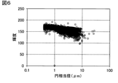
- 6 is a graph plotting the equivalent circle diameter ( ⁇ m) and the brightness of the particles contained in the MXene slurry of Example 1.
- 6 is a graph plotting the equivalent circle diameter ( ⁇ m) and the brightness of the particles contained in the MXene slurry of Example 2.
- (A) is a graph showing the distribution ratio of particle luminance contained in the MXene slurry of Comparative Example 1 and Examples 1 and 2
- (b) is a graph showing a part of (a) enlarged. ..
- a cross-sectional SEM photograph of a conductive film (sample) with a substrate of Comparative Example 2 obtained by using the MXene slurry of Comparative Example 1 is shown.
- the cross-sectional SEM photograph of the conductive film (sample) with a substrate of Example 3 obtained by using the MXene slurry of Example 1 is shown.
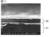
- the cross-sectional SEM photograph of the conductive film (sample) with a substrate of Example 4 obtained by using the MXene slurry of Example 2 is shown. It is a figure explaining the conductive film produced by the conventional manufacturing method, and shows the schematic schematic sectional view of the conductive film on a base material.
- a conductive film, a particulate matter, a slurry containing the particulate matter, and a method for producing a conductive film using the slurry in one embodiment of the present invention will be described in detail. Not limited.
- the conductive film 30 of the present embodiment contains particles 10 of a predetermined layered material, and the (00 l) surface (l is 2 natural) obtained by X-ray diffraction measurement of the conductive film 30.
- the half-value width of the rocking curve in the ⁇ -axis direction with respect to the peak (which is several times the number) is 10.3 ° or less.
- the conductive film 30 of the present embodiment will be described through the manufacturing method.
- the predetermined layered material that can be used in this embodiment is MXene and is defined as follows: A layered material comprising one or more layers, wherein the layer has the following formula: M m X n (In the formula, M is at least one group 3, 4, 5, 6, 7 metal, so-called early transition metals such as Sc, Ti, Zr, Hf, V, Nb, Ta, Cr, Mo and It may contain at least one selected from the group consisting of Mn.
- the layer body represented by may have a crystal lattice in which each X is located in an octahedral array of M) and the surface of the layer body (more specifically, facing each other of the layer body).
- a layered material containing a modification or termination T (T is at least one selected from the group consisting of a hydroxyl group, a fluorine atom, a chlorine atom, an oxygen atom and a hydrogen atom) present on at least one of the two surfaces thereof.
- n can be 1, 2, 3 or 4, but is not limited to this.
- M is preferably at least one selected from the group consisting of Ti, Zr, Hf, V, Nb, Ta, Cr, Mo and Mn, preferably from Ti, V, Cr and Mo. More preferably, it is at least one selected from the group.
- Such MXene can be synthesized by selectively etching (removing and optionally layering) A atoms (and optionally a portion of M atoms) from the MAX phase.
- the MAX phase is expressed by the following equation: M m AX n (In the formula, M, X, n and m are as described above, A is at least one group 12th, 13th, 14th, 15th and 16th element, usually a group A element, representatively.
- Is a group IIIA and a group IVA and more particularly may include at least one selected from the group consisting of Al, Ga, In, Tl, Si, Ge, Sn, Pb, P, As, S and Cd.
- a layer composed of A atoms is located between two layers represented by and represented by Mm Xn (each X may have a crystal lattice located in an octahedral array of M ). It has a crystal structure.
- Mm Xn a layer of X atoms
- MM X n layer a layer of A atoms
- a atom layer is arranged as a layer next to the n + 1th layer of M atoms, but is not limited to this.
- the A atom layer (and possibly part of the M atom) is removed by selectively etching (removing and possibly layering) the A atom (and possibly part of the M atom) from the MAX phase.
- etching solution usually, but not limited to, an aqueous solution of fluoroacid is used
- the etching can be carried out using an etching solution containing F ⁇ , and may be, for example, a method using a mixed solution of lithium fluoride and hydrochloric acid, a method using hydrofluoric acid, or the like.
- etching so that the number of A atoms remaining in the MXene particles is smaller.
- the fact that there are fewer A atoms remaining contributes to increasing the purity of the single-layer MXene and increasing the in-plane dimensions of the single-layer MXene particles in the particulate matter described later and the slurry containing the same. ..
- layer separation of MXene (delamination, multilayer MXene with a smaller layer of MXene, preferably single layer). It is preferable to carry out a treatment that results in layer MXene).
- the layer separation treatment causes less damage to the MXene particles.
- the layer separation process can be performed by any suitable method, such as sonication, hand shake or automatic shaker, but the sonication can cause the MXene particles to be destroyed (shredded) due to too much shear. ) Therefore, it is preferable to apply an appropriate shearing force by a hand shake or an automatic shaker.
- a hand shake or an automatic shaker When the amount of A atoms remaining in the MXene particles is smaller, the influence of the binding force of the A atoms is smaller, so that the MXene particles can be effectively layer-separated with a smaller shearing force.
- M can be titanium or vanadium and X can be a carbon atom or a nitrogen atom.
- the MAX phase is Ti 3 AlC 2 and MXene is Ti 3 C 2 T s (in other words, M is Ti, X is C, n is 2 and m is 3). Is).
- the MXene particles 10 thus synthesized are, as schematically shown in FIG. 2, particles of a layered material containing one or more MXene layers 7a, 7b (as an example of the MXene particles 10, FIG. 2 ( There may be one layer of MXene particles 10a in a) and two layers of MXene particles 10b in FIG. 2B), but not limited to these examples). More specifically, the MXene layers 7a and 7b are formed on the surface of the layer body ( MmXn layer) 1a and 1b represented by MmXn and the surface of the layer body 1a and 1b (more specifically, in each layer).
- the MXene particles 10 may be a plurality of MXene particles even if the MXene layers are individually separated and exist in one layer (a single-layer structure shown in FIG. 2A, so-called single-layer MXene particles 10a).
- the particles of the laminated body in which the layers are laminated apart from each other may be used, or a mixture thereof may be used.
- the MXene particles 10 can be particles (also referred to as powders or flakes) as an aggregate composed of single-layer MXene particles 10a and / or multilayer MXene particles 10b.
- multi-layer MXene particles two adjacent MXene layers (eg, 7a and 7b) may not necessarily be completely separated or may be partially in contact.
- the MXene particles 10 have as many single-layer MXene particles as possible (the content ratio of the single-layer MXene particles is high) as compared with the multilayer MXene particles.
- each layer of MXene can be, for example, 0.8 nm or more and 5 nm or less, particularly 0.8 nm or more and 3 nm or less (corresponding to the above-mentioned MXene layers 7a and 7b). It may vary mainly depending on the number of M atomic layers contained in each layer).
- the interlayer distance is, for example, 0.8 nm or more and 10 nm or less. In particular, it is 0.8 nm or more and 5 nm or less, and more particularly about 1 nm.
- the thickness in the direction perpendicular to the layer of MXene particles (which can correspond to the "thickness" of MXene particles which are two-dimensional particles) is, for example, 0.8 nm or more, for example, 20 nm or less, particularly 15 nm or less, and more particularly 10 nm or less. Is.
- the total number of layers of MXene particles can be 1 or 2 or more, for example 1 or more and 10 or less, particularly 1 or more and 6 or less.
- the MXene particles are laminated (multilayer MXene) particles, it is preferable that the MXene particles have a small number of layers.
- small number of layers means, for example, that the number of layers of MXene is 6 or less.
- the thickness of the particles of the multilayer MXene having a small number of layers in the stacking direction is preferably 15 nm or less, particularly preferably 10 nm or less.
- this "multilayer MXene with a small number of layers” is also referred to as "small layer MXene”.
- most of the MXene particles are preferably single-layer MXene and / or small-layer MXene particles, and more preferably most of them are single-layer MXene particles.
- the average thickness of MXene particles is preferably 10 nm or less. The average value of this thickness is more preferably 7 nm or less, and even more preferably 5 nm or less.
- the lower limit of the thickness of the MXene particles can be 0.8 nm. Therefore, the average value of the thickness of MXene particles can be about 1 nm or more.
- the dimensions in a plane (two-dimensional sheet surface) parallel to the layer of MXene particles can be, for example, 0.1 ⁇ m or more, particularly 1 ⁇ m or more. For example, it can be 200 ⁇ m or less, particularly 40 ⁇ m or less.
- these dimensions described above are number average dimensions (for example, at least 40 number averages) or X-rays based on photographs of a scanning electron microscope (SEM), a transmission electron microscope (TEM), or an interatomic force microscope (AFM). It can be obtained as a distance in real space calculated from the position on the reciprocal lattice space of the (002) plane measured by the diffraction (XRD) method.
- SEM scanning electron microscope
- TEM transmission electron microscope
- AFM interatomic force microscope
- Non-Patent Document 1 investigated factors that affect the conductivity of the conductive film 30 containing MXene particles in order to achieve higher conductivity than in the past.
- MXene particles multilayer MXene particles
- the substrate surface 31a in other words, the main surface of the film
- the single-layer MXene particles (including the single-layer MXene particles) 10 are relatively randomly stacked and exist, and the impurities 19 other than the MXene particles 10 are present.
- the orientation of the MXene particles is low as a whole of the conductive film, which hinders the stacking of the MXene particles.
- the physical properties of the conductive film containing the MXene particles may differ depending on the orientation of the MXene particles in the film. As schematically shown in FIG.
- a particulate matter (which can be contained in the slurry and used in the present embodiment) as a raw material thereof is important. It turned out to be. More specifically, it is considered desirable to use a particulate matter that satisfies at least one of the following (1) and (2), particularly the following (1), preferably both the following (1) and (2).
- Impurities other than MXene are as small as possible
- Single-layer MXene particles are as much as possible (high content ratio of single-layer MXene particles) than multilayer MXene particles.
- the particulate matter (which can be contained in the slurry and used in the present embodiment) satisfies at least one of the following as an index of the above (1) and / or (2). It has been found that a conductive film having sufficiently high orientation and thus high conductivity can be obtained. -The smaller the ratio of A atom to M atom, the more preferable, specifically, 0.30 mol% or less.-The smaller the ratio of particles having a thickness of more than 20 nm in the particulate matter, the more preferable, specifically. Less than 2% ⁇ It is preferable that the particulate matter does not contain particles that are too thick, specifically, the maximum thickness of the particles contained in the particulate matter is 500 nm or less.
- the particulate matter of the present embodiment contains the MXene particles 10 described above, and satisfies at least one of the following (I) to (III).
- M at least one kind of group 3, 4, 5, 6, 7 metal
- A at least one kind of group 12, 13, 14, 15, 16 element in the above formula, with respect to M.
- the proportion of A is 0.30 mol% or less
- the proportion of particles having a thickness of more than 20 nm in the particulate matter is less than 2%, preferably less than 1% (in other words, in the particulate matter).
- the proportion of particles with a thickness of 20 nm or less is 98% or more, preferably 99% or more)
- the maximum thickness of the particles contained in the particulate matter is 500 nm or less, preferably 250 nm or less, more preferably 100 nm or less, still more preferably 50 nm or less (in other words, the particulate matter has a thickness of 50 nm or less. It does not contain particles larger than 500 nm, preferably does not contain particles larger than 250 nm, more preferably does not contain particles larger than 100 nm, and even more preferably does not contain particles larger than 50 nm).
- M may be Ti and A may be Al.
- the layer separation of the MXene particles can be hindered by the bonding force of the A atom, and a shearing force larger than the bonding force of the A atom is applied to promote the layer separation.
- MXene particles are fragmented, and the in-plane dimensions of the MXene particles become smaller.
- the layer separation of the MXene particles can be effectively promoted with a smaller shearing force, so that MXene particles having a larger in-plane dimension (preferably single-layer MXene particles) can be obtained. Therefore, satisfying the above (I) can indicate that the in-plane dimensions of the MXene particles (particularly the single-layer MXene particles) are relatively large.
- the contents of M and A in the particulate matter may be determined by inductively coupled plasma emission spectroscopy (ICP-AES), fluorescent X-ray analysis (XRF), or the like. It can be measured by element (atomic) analysis, and the ratio of A to M can be calculated from these measured values.
- ICP-AES inductively coupled plasma emission spectroscopy
- XRF fluorescent X-ray analysis
- impurities other than MXene may have dimensions (thickness and / or particle size) larger than 20 nm.
- the thickness of the multilayer MXene particles is larger than the thickness of the single-layer MXene particles, and is more than 20 nm. Therefore, satisfying the above (II) can indicate that there are few impurities and the content ratio of the single-layer MXene particles is high, and the above (1) and (2) can be satisfied.
- the MAX particles may have a thickness greater than 500 nm. Therefore, satisfying the above (III) can indicate that it does not contain MAX particles, and can satisfy the above (1).
- the maximum thickness of the particles contained in the particulate matter is 500 nm or less, which may be extremely important for obtaining a highly oriented conductive film of MXene particles.
- the proportion of particles having a thickness of more than 20 nm in the particulate substance and the maximum thickness of the particles contained in the particulate substance are determined by the liquid composition containing the particulate substance in the liquid medium.
- the slurry described later is dropped onto a flat stage (for example, a silicon wafer having an arithmetic average roughness Ra of 0.5 nm or less), the liquid medium is dried and removed, and an interatomic force microscope (AFM) is used. Except for all particles in the AFM field of view (provided that two or more particles are clearly overlapped, and particles are extended outside the field of view and the overall shape of the particles cannot be predicted, for example, stacking.
- the contours (edges) of each layer are substantially aligned, it is regarded as one particle.
- most of the particles (more than half) are in the field of view, and some of the particles are in the field of view.
- the field of view of the AFM can be, for example, 30 ⁇ m ⁇ 30 ⁇ m, but is not limited thereto.
- the thickness of all particles in each field of view (provided as described above) is measured until the thickness of at least 40 particles is measured.
- the MXene particles contained in the particulate matter can be obtained from MXene.
- Planes parallel to the layers can be arranged parallel to the surface of the stage. Therefore, in the case of MXene particles, the measured value of the particle thickness can measure the thickness in the direction perpendicular to the layer of MXene (which can correspond to the "thickness" of the MXene particles).
- the value of the thickness of the MXene particles measured in this way is Note that it can be larger than the actual MXene particle thickness.
- the particulate matter of the present embodiment can be defined as follows.
- the brightness (A) in which the ratio of the particles decreases to 1% or less on the higher brightness side than the peak (P) of the brightness is specified.
- the particles exhibiting peak luminance are considered to be single-layer MXene particles.
- the particles exhibiting a luminance (P ⁇ W) within 1 times the luminance width (W) with respect to the peak luminance (P) are considered to be single-layer / small-layer MXene particles.
- Particles exhibiting a brightness (smaller than PW and P-3W or more) smaller than 1 time and 3 times or less of the brightness width (W) with respect to the peak brightness (P) are (thicker than small-layer MXene particles). It is considered to be a multi-layer MXene particle.
- Particles exhibiting a small brightness (less than P-3W) that is more than three times the brightness width (W) with respect to the peak brightness (P) are considered to be very thick particles (such particles are very thick).
- the particulate matter of the present embodiment contains the MXene particles 10 described above, and may satisfy the following (IV), and may optionally satisfy at least one of the above (I) to (III).
- the total proportion of particles exhibiting ultra-low brightness (less than P-3W) is less than 0.1%.
- the distribution ratio of the brightness of the particles of the particulate matter is determined by dropping a liquid composition (or a slurry described later) containing the particulate matter in a liquid medium onto a glass plate using a particle image analyzer. Then, cover it with a cover glass, irradiate it with light with a backlight, measure the brightness of the transmitted light while analyzing the transmitted light, and measure the brightness of the transmitted light, and the ratio of the number of particles showing the brightness within a predetermined range to the total number of particles ( %) Is obtained.
- the total number of particles to be measured shall be at least 10,000.
- the predetermined range of luminance when obtaining the luminance distribution can be appropriately selected, and may be, for example, 10.
- the slurry of the present embodiment may be a dispersion liquid and / or a suspension containing the above-mentioned particulate matter in a liquid medium.
- the liquid medium can be an aqueous medium and / or an organic medium, preferably an aqueous medium.
- the aqueous medium is typically water, and in some cases, contains other liquid substances in a relatively small amount (for example, 30% by mass or less, preferably 20% by mass or less based on the whole aqueous medium) in addition to water. May be good.
- the organic medium may be, for example, N-methylpyrrolidone, N-methylformamide, N, N-dimethylformamide, ethanol, methanol, dimethyl sulfoxide, ethylene glycol, acetic acid, isopropyl alcohol and the like.
- the concentration of MXene particles 10 (including single-layer MXene particles 10a and multilayer MXene particles 10b) in the slurry of the present embodiment can be appropriately selected depending on the method of applying the slurry and the like, but is finally conductive with high orientation. In order to obtain a film, it is preferably 10 mg / mL or more and 30 mg / mL or less. When it is 10 mg / mL or more, the single-layer MXene particles are easily oriented with each other.
- the concentration of MXene particles in the slurry is set to 10 mg / mL or more and 30 mg / mL or less to vaporize the liquid medium. It is preferable to suppress the disorder of the orientation state due to.
- the concentration of MXene particles 10 is understood as the solid content concentration in the slurry, and the solid content concentration can be measured by using, for example, a heat-dry weight measurement method, a freeze-dry weight measurement method, a filtration weight measurement method, or the like.
- the ratio of the single-layer MXene particles 10a to the MXene particles 10 is extremely high, and impurities other than the MXene particles 10 are small.
- the slurry of this embodiment can be understood as a highly purified MXene slurry.
- the slurry of the present embodiment is preferably highly dispersed without agglomeration of MXene particles 10.
- the slurry of the present embodiment can be obtained by obtaining a crude MXene slurry and then performing operations of centrifugation and recovery / separation / removal of the supernatant on the crude MXene slurry in multiple steps. More specifically, it is preferable that the operations of centrifugation and recovery of the supernatant are carried out in two or more steps, and the operations of centrifugation and separation and removal of the supernatant are carried out in the final step.
- the crudely purified slurry may contain desired single-layer MXene particles and multilayer MXene particles that have not been monolayered due to insufficient layer separation (delamination) as MXene particles, and further contain impurities other than MXene particles (unreacted). MAX particles and the above-mentioned by-products etc.) may be included.
- the layer separation can occur by applying a shear force larger than the intermolecular force acting between the MXene layers to the multilayer MXene, but the layer cannot be separated unless the shear force is sufficient (single layer). If the shearing force is too large, the MXene will be destroyed (divided into minute MXenes), so it is important to apply an appropriate shearing force. Appropriate shear forces can be applied using a handshake, an automatic shaker, or the like, as described above.
- the crude MXene slurry was highly purified by performing the operations of centrifugation and recovery / separation and removal of the supernatant in multiple steps (adding a (fresh) liquid medium as necessary).
- the MXene slurry of the present embodiment can be obtained.
- FIG. 3 schematically shows a case where the crudely purified MXene slurry is subjected to the operations of centrifugation and recovery of the supernatant in one step.
- the crude MXenes slurry contains single-layer MXene particles 10a and multilayer MXene particles 10b as MXene particles 10 and impurities (unreacted MAX particles and the above-mentioned by-products, etc.) 15. It is contained in the liquid medium 19.
- the crudely purified slurry is largely separated into a supernatant rich in single-layer MXene particles and a precipitate rich in multilayer MXene particles and impurities 11.
- the unreacted MAX particles are relatively heavy like the multilayer MXene particles, and therefore tend to sink more easily than the single-layer MXene particles.
- AlF 3 is relatively heavy (the specific gravity of AlF 3 is 3 g / cm). 3 ) Since the shape seems to be granular, it tends to sink more easily than the single-layer MXene particles. If AlF 3 is present between the layers of the multilayer MXene particles, it is considered that they sink together. On the other hand, it is considered that they sink together.
- the layered MXene particles have a two-dimensional shape with a large aspect ratio, they tend to be difficult to sink.
- This supernatant is recovered by, for example, decantation shown in FIG. 3 (c), and is a fresh liquid as needed.
- a medium is added to obtain a slurry after one-step operation as shown in FIG. 3 (d).
- the multilayer MXene particles 10b and impurities (unreacted MAX particles and the above-mentioned by-products, etc.) 15 are more effective than the crude purified slurry before the operation (FIG. 3A). It has been reduced to.
- the operation of centrifugation and recovery of the supernatant is carried out in two or more steps.
- the supernatant is separated and removed by decantation or the like.
- a highly purified MXene slurry of the present embodiment can be obtained. Since a large amount of fine MXene particles can be distributed to the supernatant separated and removed in the final step, the finally obtained MXene slurry of the present embodiment is finer than the MXene slurry before the final step operation. MXene particles are effectively reduced. As described above, it is possible to obtain a highly purified MXene slurry of the present embodiment containing a high proportion of single-layer MXene particles.
- the particles that settle are roughly determined by the centrifugal force and time, so whether the centrifugation is performed in only one stage or in multiple stages, centrifugation is performed. It is understood that if the force and total time are the same, the supernatant recovered after centrifugation will be in the same state. However, in reality, when the supernatant (the part where a large amount of single-layer MXene particles are distributed) is recovered after centrifugation, the sediment (multilayer MXene particles and impurities) soars up and mixes with the supernatant, so that the supernatant is separated.
- the supernatant portion collected after centrifugation differs between the case where the above is carried out in only one step and the case where the above is carried out in multiple steps.
- a highly purified MXene slurry of the present embodiment can be obtained.
- the operations of centrifugation and recovery / separation / removal of the supernatant are carried out in multiple steps to obtain a single layer. It is preferable to obtain a MXene slurry having a high MXene purity.
- the total number of multi-step operations of centrifugation and recovery / removal of the supernatant is two or more, preferably three or more.
- the centrifugal force and time for centrifugation can be set as appropriate.
- the centrifugal force can be, for example, a relative centrifugal force (RCF) of 3000 ⁇ g or more and 4500 ⁇ g or less, and when the RCF is 4500 ⁇ g or less, it is possible to suppress the destruction of the single-layer MXene particles, and the RCF When it is 3000 ⁇ g or more, the single-layer MXene particles can be effectively separated from the multilayer MXene particles and impurities.
- RCF relative centrifugal force
- the centrifugation time can be, for example, 3 minutes or more and 60 minutes or less, and by 60 minutes or less, it is possible to suppress the aggregation of MXene particles and the re-multilayering of single-layer MXene particles, and it is 3 minutes or more. Therefore, the single-layer MXene particles can be effectively separated from the multilayer MXene particles and impurities.
- the time of the centrifuge can be set longer as the steps progress. However, it should be noted that if the centrifugation time is too long, the single-layer MXene particles will be compressed for a long time, resulting in re-multilayering.
- the conductive film 30 of the present embodiment can be manufactured by using the MXene slurry of the present embodiment adjusted as described above.
- the base material 31 is not particularly limited as long as it has a flat surface 31a (see FIG. 1), and may be made of any suitable material.
- the base material may be, for example, a resin film, a metal foil, a printed wiring board, a mountable electronic component, a metal pin, a metal wiring, a metal wire, or the like.
- the orientation of the conductive film formed on the substrate 31 becomes low, and the surface of the conductive film becomes rough, which is not preferable.
- the surface 31a of the base material 31 may have a surface smoothness equal to or higher than that desired for the conductive film 30, and may typically have an arithmetic mean roughness of 120 nm or less.
- the MXene slurry of the present embodiment is sufficiently on the substrate surface 31a. It is preferable to get wet and spread.
- the substrate surface 31a may be preliminarily hydrophilized to improve wettability.
- the method of applying the slurry of the present embodiment on the base material 31 is only required to be able to obtain the conductive film 30 of the present embodiment having high orientation of MXene particles. More specifically, the application of the slurry may be carried out by spray, spincast or blade method, where the MXene particles are well stacked and the distance between the MXene particles is reduced, whereby the orientation is high and the density is high. It is possible to obtain a conductive film 30 having a smooth surface at (high density). Among them, the spray can apply the slurry (including MXene particles 10 and the liquid medium) of the present embodiment thinly to the base material 31 (to form a thin precursor), and thus to the base material surface 31a.
- the MXene particles 10 can be supplied in a state of being oriented (arranged flatly) in parallel as much as possible (at this time, the surface tension of the liquid medium can also preferably act).
- the nozzle used for spraying is not particularly limited.
- Step (b) the precursor on the substrate 31 is dried.
- drying means removing the liquid medium that may be present in the precursor.
- drying Even if the drying is performed under mild conditions such as natural drying (typically placed in an air atmosphere under normal temperature and pressure) or air drying (blowing air), warm air drying (spraying heated air) is performed. ), Heat drying, and / or vacuum drying may be performed under relatively active conditions.
- mild conditions such as natural drying (typically placed in an air atmosphere under normal temperature and pressure) or air drying (blowing air), warm air drying (spraying heated air) is performed. ), Heat drying, and / or vacuum drying may be performed under relatively active conditions.
- steps (a) (formation of the precursor) and the steps (b) (drying) are repeated twice or more in total until the desired conductive film thickness is obtained.
- step (a) a small amount of slurry is applied so that the MXene particles 10 can be supplied in a state of being oriented as parallel to the substrate surface 31a as possible. It is preferable to form a thin precursor.
- the thin precursor is used so as not to disturb the supply state (oriented state) of the MXene particles 10 as much as possible (do not form large voids) when the liquid medium is dried and removed from the precursor. It is preferable to sufficiently dry each time until the liquid medium does not remain substantially.
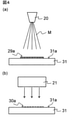
- the combination of spraying and drying may be repeated a plurality of times. More specifically, as shown in FIG. 4A, a small amount of slurry is sprayed from the nozzle 20 toward the substrate surface 31a as mist M (indicated by a dotted line in the figure), and MXene particles are liquid medium.
- the precursor layer (first layer) 29a contained therein is formed.
- the heated air is blown from the warm air dryer 21 in the direction toward the precursor layer 29a on the substrate surface 31a (indicated by the dotted arrow in the figure).
- the liquid medium is removed from the precursor layer 29a to form a conductive layer (first layer) 30a composed of MXene particles.
- a conductive film 30 in which a plurality of conductive layers 30a, 30b, 30c ... (not shown) are laminated can be formed.
- the thickness of one conductive layer formed by such spraying and drying is not particularly limited, but may be, for example, 0.01 ⁇ m or more and 1 ⁇ m or less. The number of repeated sprays and dryings can be appropriately selected depending on the thickness desired for the conductive film 30.
- the conductive film 30 of the present embodiment is manufactured.
- the conductive film 30 contains MXene particles 10, and preferably the liquid medium of the slurry of the present embodiment does not substantially remain.
- the conductive film 30 does not include a so-called binder.
- the MXene particles 10 exist in a relatively aligned state in the finally obtained conductive film 30, and more specifically, the substrate surface 31a (in other words, the conductive film).
- the substrate surface 31a in other words, the conductive film.
- the conductive film 30 having high orientation of the MXene particles 10. According to the conductive film 30, surface contact between the MXene particles 10 is achieved, the contact between the MXene particles 10 is good, and high conductivity can be obtained.
- the conductive film 30 of the present embodiment has a half width at half maximum of the ⁇ -axis direction locking curve with respect to the peak of the (00 l) plane (l is a natural number multiple of 2) obtained by X-ray diffraction measurement thereof. It is 3 ° or less.
- the conductive film containing MXene particles is a general term for MXene particles (single-layer MXene particles and multilayer MXene particles, and single-layer MXene particles are also referred to as "nanosheets" or "single flakes". Can be formed by stacking each other, and it can be considered that the conductivity of such a conductive film is dominated by the orientation of the MXene particles. In order to obtain a conductive film having high conductivity, it is preferable that the MXene particles are oriented as parallel and uniformly as possible, in other words, the orientation is high.
- the half width at half maximum of the ⁇ -axis direction locking curve for the peak of the (00 l) plane (l is a natural number multiple of 2) obtained by X-ray diffraction measurement (hereinafter, simply ". ⁇ -axis direction locking curve half width ") can be applied.
- the narrower the half width of the locking curve in the ⁇ -axis direction the higher the orientation of the MXene particles in the conductive film.
- XRD X-ray diffraction
- ⁇ -axis direction locking curve is obtained by a ⁇ -axis direction scan fixed at 2 ⁇ where the peak of the (00 l) plane is obtained.
- One peak is observed in the ⁇ -axis direction locking curve, and the width (°) of the ⁇ -axis angle when the intensity of this peak is halved is defined as the “ ⁇ -axis direction locking curve full width at half maximum”.
- a microscopic X-ray diffraction ( ⁇ -XRD) device equipped with a two-dimensional detector can be used, and the resulting two-dimensional X-ray diffraction image is converted into one dimension (fitting appropriately).
- XRD profile of ⁇ -axis direction scan (vertical axis is intensity, horizontal axis is 2 ⁇ , generally referred to as “XRD profile”) and ⁇ -axis direction locking curve profile (vertical) with respect to a predetermined 2 ⁇ .
- the axis is the strength and the horizontal axis is ⁇ ).
- the (00l) plane of MXene basically indicates the crystal c-axis direction of MXene, and the peak of the (00l) plane can be observed in the XRD profile of the ⁇ -axis direction scan.
- Bragg's diffraction is performed at ⁇ corresponding to the length d of the periodic structure of MXene (periodic structure along the stacking direction in the laminated structure of single-layer MXene and / or multilayer MXene).
- the peak of the (00l) plane can be observed, but the length d of the periodic structure is the interlayer distance of MXene (single layer MXene and Regardless of the multilayer MXene, it refers to the distance between any two adjacent MXene layers in the conductive film), and can be shifted depending on the thickness of the MXene layer and the like.
- M m X n MXene represented by Ti 3 C 2
- the intensity is maximized (peak is observed) at an angle perpendicular to (or near) the main plane of the conductive film.
- the more the MXene crystals are aligned in the c-axis direction the more remarkable the decrease in strength is when the MXene is deviated from the vertical angle. Therefore, the smaller the half-value width of the peak in the ⁇ -axis direction locking curve, the more aligned the crystal c-axis directions of MXene, in other words, the higher the orientation (see FIG. 1).
- the conductive film of the present embodiment has a half width of the locking curve in the ⁇ -axis direction of 10.3 ° or less and the orientation of MXene particles is high, a high conductivity, for example, a conductivity of 10,000 S / cm or more can be obtained. be able to.
- the full width at half maximum of the locking curve in the ⁇ -axis direction is preferably 8.8 ° or less, whereby even higher conductivity can be realized.
- There is no particular lower limit for the half-value width of the locking curve in the ⁇ -axis direction but it can be, for example, 3 ° or more.
- the conductive film of the present embodiment may have a conductivity of 12000 S / cm or more.
- the conductivity of the conductive film can be preferably 14,000 S / cm or more, and there is no particular upper limit, but it can be, for example, 30,000 S / cm or less.
- the conductivity can be calculated by measuring the resistivity and thickness of the conductive film and using these measured values.
- the half width of the locking curve in the ⁇ -axis direction is 10.3 ° or less, and the orientation of the MXene particles is high, so that a high density can be obtained.
- a density of .00 g / cm 3 or more can be achieved.
- the high orientation and density indicate a high proportion of single-layer MXene particles in the conductive film.
- the density of the conductive film can be preferably 3.40 g / cm 3 or more, and there is no particular upper limit, but it can be, for example, 4.5 g / cm 3 or less.
- the density can be calculated from the measured values by measuring the mass and thickness of the conductive film for a portion of the conductive film having a predetermined area.
- the half-value width of the locking curve in the ⁇ -axis direction is 10.3 ° or less, and the orientation of the MXene particles is high, so that high surface smoothness can be obtained, and specifically. Can achieve an arithmetic mean roughness (Ra) of 120 nm or less.
- Ra can be preferably 100 nm or less, more preferably 80 nm or less, and there is no particular lower limit, but it can be, for example, 1 nm or more.
- Ra can measure the exposed surface of the conductive film using a surface roughness measuring machine.
- the conductive film of the present embodiment may have a form as a so-called film, and specifically, may have two main surfaces facing each other.
- the thickness of the conductive film, the shape and dimensions when viewed in a plan view, and the like can be appropriately selected depending on the use of the conductive film.
- the conductive film of this embodiment can be used for any suitable application. It is suitably used as an electromagnetic shield (EMI shield) that requires high conductivity.
- EMI shield electromagnetic shield
- an electromagnetic shield having a high shielding rate (EMI shielding property) can be obtained.
- the EMI shielding property is calculated with respect to the conductivity as shown in Table 1 based on the following formula (1).
- SE EMI shielding (dB)
- ⁇ conductivity (S / cm)
- f the frequency of electromagnetic waves (MHz)
- t the film thickness (cm).
- the conductivity is 10,000 S / cm or more, high EMI shielding property can be obtained.
- the conductivity is 10000 S / cm or more, preferably 12000 S / cm or more. Therefore, when the thickness is constant, higher EMI shielding property can be obtained or the thickness can be obtained. A sufficient EMI shielding effect can be obtained even if the amount is reduced.
- the conductive film of the present invention may be manufactured by a method different from the manufacturing method in the above-described embodiment, and the method for manufacturing the conductive film of the present invention is the conductive film in the above-described embodiment. Please note that you are not limited to what you offer.
- TiC powder, Ti powder and Al powder (all manufactured by High Purity Chemical Laboratory Co., Ltd.) were placed in a ball mill containing zirconia balls at a molar ratio of 2: 1: 1 and mixed for 24 hours.
- the obtained mixed powder was calcined at 1350 ° C. for 2 hours in an Ar atmosphere.
- the fired body (block) thus obtained was crushed with an end mill to a maximum size of 40 ⁇ m or less.
- Ti 3 AlC 2 particles (powder) were obtained as MAX particles.
- the Ti 3 AlC 2 particles (powder) obtained above were added to 9 mol / L hydrochloric acid together with LiF (1 g of LiF and 10 mL of 9 mol / L hydrochloric acid per 1 g of Ti 3 AlC 2 particles), 35.
- the mixture was stirred at ° C. for 24 hours with a stirrer to obtain a solid-liquid mixture (suspension) containing a solid component derived from Ti 3 AlC 2 particles.
- the operation of washing with pure water and separating and removing the supernatant by decantation using a centrifuge was repeated about 10 times.
- the mixture in which pure water was added to the sediment was stirred with an automatic shaker for 15 minutes. As a result, a crudely purified MXene slurry was obtained.
- the MXene slurry after the one-step operation was placed in a centrifuge tube having a capacity of 50 mL, and centrifuged at 3500 ⁇ g RCF for 15 minutes using a centrifuge. The supernatant separated by this was recovered by decantation to obtain a MXene slurry after a two-step operation. The remaining sediment (high-concentration slurry) excluding the supernatant was diluted by adding pure water to obtain the MXene slurry (solid content concentration 15 mg / mL) of Comparative Example 1.
- the MXene slurry after the two-step operation was placed in a centrifuge tube having a capacity of 50 mL, and centrifuged at 3500 ⁇ g RCF for 30 minutes using a centrifuge. The supernatant separated by this was recovered by decantation to obtain a MXene slurry after a three-step operation. The remaining sediment (high-concentration slurry) excluding the supernatant was diluted by adding pure water to obtain the MXene slurry of Example 1 (solid content concentration 15 mg / mL).
- the MXene slurry after the three-step operation was placed in a centrifuge tube having a capacity of 50 mL, and centrifuged at 3500 ⁇ g RCF for 45 minutes using a centrifuge. The supernatant separated by this was separated and removed by decantation. The separated supernatant was not used thereafter. The remaining sediment (high-concentration slurry) excluding the supernatant was diluted by adding pure water to obtain the MXene slurry of Example 2 (solid content concentration 15 mg / mL).
- the distribution ratio of the brightness of the particles (the ratio of the number of particles having a predetermined range of brightness based on the total number of particles (100%)) was investigated.
- the predetermined range is set to 10, and the brightness is 60 or less, 60 or more and 70 or less, 70 or more and 80 or less, ..., 180 or more and 190 or less, 190 or more and 200 or less, and 200 or more, for example, more than 120.
- the particles having a brightness of 130 or less were labeled as particles having a brightness of "130".
- the results are shown in FIG. Highly bright particles are considered to be thin particles, i.e.
- the MXene slurry of Example 1 (FIG. 6) has a brightness of 100 or less (ie, considerably larger in thickness) than the MXene slurry of Comparative Example 1 (FIG. 5). Almost no particles are seen, and it is understood that the single-layer MXene particles can be highly purified. Further, in the MXene slurry of Example 2 (FIG.
- the proportion of particles having a luminance of 100 or more, specifically 0.13%, and the proportion of particles having a luminance of 100 or less are The total was 0.1% or more, specifically 0.35%.
- the proportion of particles having a luminance of 100 is less than 0.1%, specifically 0.01%, and the proportion of particles having a luminance of 100 or less is totaled. Even less than 0.1%, specifically 0.01%.
- Example 1 the thickness of eight particles existing in the visual field 1 is measured, then the thickness of the eight particles existing in the visual field 2 is measured, and ... 5) Next, the thicknesses of the 6 particles existing in the visual field 6 were measured, and the measurement results of the total thickness of 42 particles were obtained.
- the MXene slurry of Comparative Example 1 has 3 particles having a thickness of more than 20 nm out of a total of 48 particles, and therefore, the proportion of particles having a thickness of more than 20 nm in the particulate matter. was 6%.
- the maximum thickness of the particles contained in the particulate matter exceeds 500 nm, and the particles having a thickness of more than 500 nm are considered to be MAX particles.
- the MXene slurry of Example 1 out of a total of 42 particles, zero particles have a thickness of more than 20 nm, and therefore, the proportion of particles having a thickness of more than 20 nm in the particulate matter is 0%. Met.
- the MXene slurry of Example 1 had a maximum thickness of particles contained in the particulate matter of about 13 nm, only one particle having a thickness of more than 10 nm, and all other particles having a thickness of 10 nm or less.
- the particle thickness distribution measured by AFM shown in Table 3 generally corresponds to the brightness distribution ratio measured by the particle image analyzer (“Moforogi 4”) shown in FIG.
- the particles exhibiting a brightness of 150 or more and 190 or less in FIG. 8 are considered to be single-layer / small-layer MXene particles, which may be considered to correspond to particles having a thickness of 10 nm or less in AFM measurement.
- Particles exhibiting a brightness of 110 or more and less than 150 in FIG. 8 are considered to be multilayer MXene particles (thicker than small-layer MXene particles), which are considered to correspond to particles having a thickness of more than 10 nm and a thickness of 30 nm or less as measured by AFM. It's okay.
- Particles exhibiting a brightness of less than 110 (100 or less) in FIG. 8 are considered to be very thick particles, which may be considered to correspond to particles greater than 30 nm in AFM measurements.
- the ratio of Al to Ti (mol%) is reduced in the MXene slurry of Example 1 as compared with the MXene slurry of Comparative Example 1 (more specifically, Al to Ti in the slurry). It is understood that the monolayer MXene particles can be highly purified. Further, it is understood that in the MXene slurry of Example 2, the ratio of Al to Ti (mol%) is further reduced, and the single-layer MXene particles can be further purified.
- Each MXene slurry prepared above was diluted by adding pure water to prepare a slurry having a solid content concentration of about 15 mg / mL.
- a polyethylene terephthalate film having a thickness of 50 ⁇ m and having a hydrophilized surface treatment (ultraviolet-ozone treatment) was prepared as a base material. On the surface of the base material, a square area of 3 cm ⁇ 3 cm was left exposed, and the periphery thereof was masked with scotch tape.
- the substrate was sprayed at 0.40 MPa (absolute pressure). After spraying, it was dried by blowing warm air with a hand dryer (EH5206P-A manufactured by Panasonic Corporation).
- the thickness of one layer of the precursor by spraying was several tens of nm. After spraying one layer of the precursor, it was sufficiently dried by blowing warm air (the temperature of the substrate during drying was considered to be 40 ° C. or higher, and the drying was effectively promoted).
- the spraying and drying operations were repeated 100 times or more in total.
- ⁇ Axial locking curve full width at half maximum
- the conductive film (sample) with a base material prepared above is punched out or cut out together with the base material, and XRD measured using ⁇ -XRD (AXS D8 DISCOVER with GADDS, manufactured by Bruker Corporation).
- the peak (in the vicinity) (formula: the peak of the (0010) plane of MXene whose M m X n is represented by Ti 3 C 2 ) is investigated, and the ⁇ -axis direction locking curve is obtained for this peak, and the ⁇ -axis direction locking curve is obtained.
- the half price range was calculated.
- the full width at half maximum of the locking curve in the ⁇ -axis direction was taken as the average value of the measured values at two points obtained by the XRD measurement.
- the results are shown in Table 5 (in Table 5, the half-value width of the ⁇ -axis direction locking curve is simply referred to as "half-value width").
- the conductivity (S / cm) of the conductive film is measured by using the portion of the conductive film (sample) with a substrate prepared above that is not the portion punched out above (the same applies hereinafter). did. More specifically, the conductivity is the resistivity (surface resistivity) ( ⁇ ) and the thickness ( ⁇ m) (minus the thickness of the base material) three times at five points in total at the four corners and the center per sample. The resistivity (S / cm) was calculated from the average value of the three measurements, and the average value of the resistivity of the five points obtained by this was adopted. A resistivity meter (Roresta AX MCP-T370 manufactured by Mitsubishi Chemical Analytical Corporation) was used for resistivity measurement. A micrometer (Mitutoyo Co., Ltd., MDH-25MB) was used for the thickness measurement. The results are also shown in Table 5.
- Density Of the conductive film (sample) with a substrate prepared above a total of 5 points, the same as those for the thickness measurement above, were cut out in a 1 cm ⁇ 1 cm area, and the cut out parts were before peeling the conductive film and The subsequent mass was measured, and the mass of the conductive film per unit area (1 cm 2 ) was calculated as the difference between the measured values. Then, the density of the conductive film was calculated by dividing the mass of the conductive film per unit area (1 cm 2 ) by the thickness obtained by the above thickness measurement. The results are also shown in Table 5.
- Ra Arimetic Mean Roughness
- a label having a color and characters on the label surface is obliquely opposed to the exposed surface of the conductive film (inner angle). Approximately 45 °), and the reflection of the label surface on the exposed surface of the conductive film was observed.
- On the label surface (i) a black area, (ii) an area with black characters on a white background, (iii) an area with white and black characters on a green background, and (iv) a green character and black on a white background.
- the areas where the letters were written were lined up parallel to each other. The higher the degree of reflection on the conductive film, the higher the light reflectivity and the higher the orientation.
- the reflection on the label surface was hardly observed, and (i) a blackish region, (ii) a whitish region, (iii) a greenish region, and (iv) a whitish region could be discriminated. It was about.
- reflection on the label surface was observed, and (i) black areas, (ii) white areas with black characters, and (iii) green areas with white and black characters. In addition, (iv) what appeared to be green and black characters could be identified in the white area.
- the single-layer MXene particles were laminated with generally good orientation. Further, in the conductive film of Example 4 (FIG. 11), the disorder of the layer structure of MXene was not observed, and the single-layer MXene particles were laminated with extremely high orientation.
- the conductive film of the present invention can be used for any suitable application, and can be particularly preferably used, for example, as an electromagnetic shield.
Landscapes
- Physics & Mathematics (AREA)
- Chemical & Material Sciences (AREA)
- Dispersion Chemistry (AREA)
- Spectroscopy & Molecular Physics (AREA)
- Electromagnetism (AREA)
- Engineering & Computer Science (AREA)
- Microelectronics & Electronic Packaging (AREA)
- Laminated Bodies (AREA)
- Conductive Materials (AREA)
- Shielding Devices Or Components To Electric Or Magnetic Fields (AREA)
Priority Applications (3)
| Application Number | Priority Date | Filing Date | Title |
|---|---|---|---|
| CN202180060354.3A CN116134978B (zh) | 2020-08-13 | 2021-08-05 | 导电性膜、粒子状物质、浆料和导电性膜的制造方法 |
| JP2022542831A JP7480848B2 (ja) | 2020-08-13 | 2021-08-05 | 導電性膜、粒子状物質、スラリーおよび導電性膜の製造方法 |
| US18/158,600 US20230217635A1 (en) | 2020-08-13 | 2023-01-24 | Conductive film, particulate matter, slurry, and method for producing conductive film |
Applications Claiming Priority (2)
| Application Number | Priority Date | Filing Date | Title |
|---|---|---|---|
| JP2020136819 | 2020-08-13 | ||
| JP2020-136819 | 2020-08-13 |
Related Child Applications (1)
| Application Number | Title | Priority Date | Filing Date |
|---|---|---|---|
| US18/158,600 Continuation US20230217635A1 (en) | 2020-08-13 | 2023-01-24 | Conductive film, particulate matter, slurry, and method for producing conductive film |
Publications (1)
| Publication Number | Publication Date |
|---|---|
| WO2022034853A1 true WO2022034853A1 (ja) | 2022-02-17 |
Family
ID=80247888
Family Applications (1)
| Application Number | Title | Priority Date | Filing Date |
|---|---|---|---|
| PCT/JP2021/029151 Ceased WO2022034853A1 (ja) | 2020-08-13 | 2021-08-05 | 導電性膜、粒子状物質、スラリーおよび導電性膜の製造方法 |
Country Status (4)
| Country | Link |
|---|---|
| US (1) | US20230217635A1 (https=) |
| JP (1) | JP7480848B2 (https=) |
| CN (1) | CN116134978B (https=) |
| WO (1) | WO2022034853A1 (https=) |
Cited By (2)
| Publication number | Priority date | Publication date | Assignee | Title |
|---|---|---|---|---|
| WO2023223780A1 (ja) * | 2022-05-16 | 2023-11-23 | 株式会社村田製作所 | 導電性2次元粒子およびその製造方法、導電性膜、導電性ペースト、ならびに導電性複合材料 |
| JPWO2023233783A1 (https=) * | 2022-06-01 | 2023-12-07 |
Citations (5)
| Publication number | Priority date | Publication date | Assignee | Title |
|---|---|---|---|---|
| CN107058851A (zh) * | 2016-12-29 | 2017-08-18 | 上海大学 | 一种二维片层材料增强的金属基复合材料 |
| KR101966582B1 (ko) * | 2018-02-02 | 2019-04-05 | 성균관대학교산학협력단 | 2차원 맥세인 박막의 제조방법 |
| CN110698847A (zh) * | 2019-10-21 | 2020-01-17 | 西北工业大学 | 水性聚氨酯-MXene电磁屏蔽仿生纳米复合材料膜及制备方法 |
| US20200163261A1 (en) * | 2018-01-05 | 2020-05-21 | Korea Institute Of Science And Technology | Method for manufacturing electromagnetic interference shielding film |
| US20200240000A1 (en) * | 2017-10-16 | 2020-07-30 | Drexel University | Mxene layers as substrates for growth of highly oriented perovskite thin films |
Family Cites Families (11)
| Publication number | Priority date | Publication date | Assignee | Title |
|---|---|---|---|---|
| JP5145938B2 (ja) * | 2005-09-16 | 2013-02-20 | 大日本印刷株式会社 | 帯電防止防眩フィルム |
| JP5387034B2 (ja) * | 2009-02-20 | 2014-01-15 | 大日本印刷株式会社 | 導電性基板 |
| WO2016049109A2 (en) * | 2014-09-25 | 2016-03-31 | Drexel University | Physical forms of mxene materials exhibiting novel electrical and optical characteristics |
| JP6460383B2 (ja) * | 2014-12-11 | 2019-01-30 | Dic株式会社 | 導電性積層体及びその製造方法 |
| JP2017191928A (ja) * | 2016-04-11 | 2017-10-19 | 株式会社リコー | 電気機械変換電子部品、液体吐出ヘッド、液体吐出ユニット及び液体を吐出する装置 |
| KR102200472B1 (ko) * | 2016-04-22 | 2021-01-08 | 한국과학기술연구원 | Emi 차폐용 2차원 금속 탄화물, 질화물 및 탄질화물 필름 및 복합체 |
| US20180338396A1 (en) * | 2017-05-16 | 2018-11-22 | Murata Manufacturing Co., Ltd. | Electronic component having electromagnetic shielding and method for producing the same |
| US11312631B2 (en) * | 2017-09-28 | 2022-04-26 | Murata Manufacturing Co., Ltd. | Aligned film and method for producing the same |
| US11202398B2 (en) * | 2017-09-28 | 2021-12-14 | Murata Manufacturing Co., Ltd. | Electromagnetic shielding material and method for producing the same |
| CN110972477A (zh) * | 2018-12-28 | 2020-04-07 | 株式会社亚都玛科技 | MXene粒子材料、MXene粒子材料的制造方法和二次电池 |
| CN111312434B (zh) * | 2020-02-27 | 2021-05-04 | 北京化工大学 | 基于金属纳米线的多层结构透明电磁屏蔽膜及其制备方法与应用 |
-
2021
- 2021-08-05 CN CN202180060354.3A patent/CN116134978B/zh active Active
- 2021-08-05 JP JP2022542831A patent/JP7480848B2/ja active Active
- 2021-08-05 WO PCT/JP2021/029151 patent/WO2022034853A1/ja not_active Ceased
-
2023
- 2023-01-24 US US18/158,600 patent/US20230217635A1/en active Pending
Patent Citations (5)
| Publication number | Priority date | Publication date | Assignee | Title |
|---|---|---|---|---|
| CN107058851A (zh) * | 2016-12-29 | 2017-08-18 | 上海大学 | 一种二维片层材料增强的金属基复合材料 |
| US20200240000A1 (en) * | 2017-10-16 | 2020-07-30 | Drexel University | Mxene layers as substrates for growth of highly oriented perovskite thin films |
| US20200163261A1 (en) * | 2018-01-05 | 2020-05-21 | Korea Institute Of Science And Technology | Method for manufacturing electromagnetic interference shielding film |
| KR101966582B1 (ko) * | 2018-02-02 | 2019-04-05 | 성균관대학교산학협력단 | 2차원 맥세인 박막의 제조방법 |
| CN110698847A (zh) * | 2019-10-21 | 2020-01-17 | 西北工业大学 | 水性聚氨酯-MXene电磁屏蔽仿生纳米复合材料膜及制备方法 |
Cited By (5)
| Publication number | Priority date | Publication date | Assignee | Title |
|---|---|---|---|---|
| WO2023223780A1 (ja) * | 2022-05-16 | 2023-11-23 | 株式会社村田製作所 | 導電性2次元粒子およびその製造方法、導電性膜、導電性ペースト、ならびに導電性複合材料 |
| JPWO2023223780A1 (https=) * | 2022-05-16 | 2023-11-23 | ||
| JPWO2023233783A1 (https=) * | 2022-06-01 | 2023-12-07 | ||
| WO2023233783A1 (ja) * | 2022-06-01 | 2023-12-07 | 株式会社村田製作所 | 電極および電極の製造方法 |
| JP7750406B2 (ja) | 2022-06-01 | 2025-10-07 | 株式会社村田製作所 | 電極および電極の製造方法 |
Also Published As
| Publication number | Publication date |
|---|---|
| CN116134978B (zh) | 2025-10-21 |
| US20230217635A1 (en) | 2023-07-06 |
| JPWO2022034853A1 (https=) | 2022-02-17 |
| CN116134978A (zh) | 2023-05-16 |
| JP7480848B2 (ja) | 2024-05-10 |
Similar Documents
| Publication | Publication Date | Title |
|---|---|---|
| US9957164B2 (en) | Highly conducting graphitic films from graphene liquid crystals | |
| US10059592B1 (en) | Process for producing highly oriented graphene films | |
| US10005099B2 (en) | Production of highly oriented graphene oxide films and graphitic films derived therefrom | |
| CN110892570B (zh) | MXene粒子材料、浆料、二次电池、透明电极、MXene粒子材料的制造方法 | |
| KR101606401B1 (ko) | 다층 그래핀 피복 기판의 제조 방법 | |
| US20150217538A1 (en) | Highly oriented graphene structures and process for producing same | |
| KR102470752B1 (ko) | 고전도성 흑연 필름 및 생산 공정 | |
| US20230217635A1 (en) | Conductive film, particulate matter, slurry, and method for producing conductive film | |
| WO2022080321A1 (ja) | 導電性2次元粒子およびその製造方法、導電性膜、導電性複合材料、ならびに導電性ペースト | |
| Guo et al. | Multifunctional polyimide/boron nitride nanosheet/Ti3C2Tx MXene composite film with three-dimensional conductive network for integrated thermal conductive, electromagnetic interference shielding, and Joule heating performances | |
| US20230207152A1 (en) | Conductive two-dimensional particle and method for producing the same | |
| Kobayashi et al. | Fabrication of high concentration barium titanate/polyvinylpyrrolidone nano-composite thin films and their dielectric properties | |
| WO2022050114A1 (ja) | 導電性2次元粒子およびその製造方法 | |
| JP7042800B2 (ja) | 高配向フミン酸フィルムおよびそれから得られる高導電性黒鉛フィルムならびに同フィルムを含有するデバイス | |
| Meng et al. | Using cellulose nanocrystals for graphene/hexagonal boron nitride nanosheet films towards efficient thermal management with tunable electrical conductivity | |
| KR101494626B1 (ko) | 내마모성이 우수한 그래핀-알루미나-지르코니아 복합체의 제조방법 | |
| Chibério et al. | Al2O3 dielectric ceramic tapes containing hBN for applications on high-frequency substrates | |
| US20180050914A1 (en) | Process for Producing Highly Oriented Humic Acid Films and Highly Conducting Graphitic Films Derived Therefrom | |
| WO2022034852A1 (ja) | 膜の製造方法および導電性膜 | |
| WO2022050317A1 (ja) | 導電性膜およびその製造方法 | |
| Pradhan et al. | Specific heat and thermal conductivity measurements for anisotropic and random macroscopic composites of cobalt nanowires | |
| CN111886200A (zh) | 碳基复合材料 | |
| JP6903538B2 (ja) | 誘電体複合材料 | |
| KR102249313B1 (ko) | 무선 주파수 안테나 구조체 및 이의 제조방법 | |
| WO2024029207A1 (ja) | 液晶ポリマーフィルムおよびこれを備えた積層体、ならびに、液晶ポリマーフィルムの製造方法 |
Legal Events
| Date | Code | Title | Description |
|---|---|---|---|
| 121 | Ep: the epo has been informed by wipo that ep was designated in this application |
Ref document number: 21855932 Country of ref document: EP Kind code of ref document: A1 |
|
| ENP | Entry into the national phase |
Ref document number: 2022542831 Country of ref document: JP Kind code of ref document: A |
|
| NENP | Non-entry into the national phase |
Ref country code: DE |
|
| 122 | Ep: pct application non-entry in european phase |
Ref document number: 21855932 Country of ref document: EP Kind code of ref document: A1 |
|
| WWG | Wipo information: grant in national office |
Ref document number: 202180060354.3 Country of ref document: CN |