WO2022024228A1 - 車両の制御方法及び車両の制御システム - Google Patents
車両の制御方法及び車両の制御システム Download PDFInfo
- Publication number
- WO2022024228A1 WO2022024228A1 PCT/JP2020/028930 JP2020028930W WO2022024228A1 WO 2022024228 A1 WO2022024228 A1 WO 2022024228A1 JP 2020028930 W JP2020028930 W JP 2020028930W WO 2022024228 A1 WO2022024228 A1 WO 2022024228A1
- Authority
- WO
- WIPO (PCT)
- Prior art keywords
- vehicle
- electric motor
- driving force
- engine
- value
- Prior art date
- Legal status (The legal status is an assumption and is not a legal conclusion. Google has not performed a legal analysis and makes no representation as to the accuracy of the status listed.)
- Ceased
Links
Images


Classifications
-
- B—PERFORMING OPERATIONS; TRANSPORTING
- B60—VEHICLES IN GENERAL
- B60K—ARRANGEMENT OR MOUNTING OF PROPULSION UNITS OR OF TRANSMISSIONS IN VEHICLES; ARRANGEMENT OR MOUNTING OF PLURAL DIVERSE PRIME-MOVERS IN VEHICLES; AUXILIARY DRIVES FOR VEHICLES; INSTRUMENTATION OR DASHBOARDS FOR VEHICLES; ARRANGEMENTS IN CONNECTION WITH COOLING, AIR INTAKE, GAS EXHAUST OR FUEL SUPPLY OF PROPULSION UNITS IN VEHICLES
- B60K6/00—Arrangement or mounting of plural diverse prime-movers for mutual or common propulsion, e.g. hybrid propulsion systems comprising electric motors and internal combustion engines
- B60K6/20—Arrangement or mounting of plural diverse prime-movers for mutual or common propulsion, e.g. hybrid propulsion systems comprising electric motors and internal combustion engines the prime-movers consisting of electric motors and internal combustion engines, e.g. HEVs
- B60K6/42—Arrangement or mounting of plural diverse prime-movers for mutual or common propulsion, e.g. hybrid propulsion systems comprising electric motors and internal combustion engines the prime-movers consisting of electric motors and internal combustion engines, e.g. HEVs characterised by the architecture of the hybrid electric vehicle
- B60K6/46—Series type
-
- B—PERFORMING OPERATIONS; TRANSPORTING
- B60—VEHICLES IN GENERAL
- B60K—ARRANGEMENT OR MOUNTING OF PROPULSION UNITS OR OF TRANSMISSIONS IN VEHICLES; ARRANGEMENT OR MOUNTING OF PLURAL DIVERSE PRIME-MOVERS IN VEHICLES; AUXILIARY DRIVES FOR VEHICLES; INSTRUMENTATION OR DASHBOARDS FOR VEHICLES; ARRANGEMENTS IN CONNECTION WITH COOLING, AIR INTAKE, GAS EXHAUST OR FUEL SUPPLY OF PROPULSION UNITS IN VEHICLES
- B60K6/00—Arrangement or mounting of plural diverse prime-movers for mutual or common propulsion, e.g. hybrid propulsion systems comprising electric motors and internal combustion engines
- B60K6/20—Arrangement or mounting of plural diverse prime-movers for mutual or common propulsion, e.g. hybrid propulsion systems comprising electric motors and internal combustion engines the prime-movers consisting of electric motors and internal combustion engines, e.g. HEVs
- B60K6/42—Arrangement or mounting of plural diverse prime-movers for mutual or common propulsion, e.g. hybrid propulsion systems comprising electric motors and internal combustion engines the prime-movers consisting of electric motors and internal combustion engines, e.g. HEVs characterised by the architecture of the hybrid electric vehicle
- B60K6/44—Series-parallel type
- B60K6/442—Series-parallel switching type
-
- B—PERFORMING OPERATIONS; TRANSPORTING
- B60—VEHICLES IN GENERAL
- B60K—ARRANGEMENT OR MOUNTING OF PROPULSION UNITS OR OF TRANSMISSIONS IN VEHICLES; ARRANGEMENT OR MOUNTING OF PLURAL DIVERSE PRIME-MOVERS IN VEHICLES; AUXILIARY DRIVES FOR VEHICLES; INSTRUMENTATION OR DASHBOARDS FOR VEHICLES; ARRANGEMENTS IN CONNECTION WITH COOLING, AIR INTAKE, GAS EXHAUST OR FUEL SUPPLY OF PROPULSION UNITS IN VEHICLES
- B60K6/00—Arrangement or mounting of plural diverse prime-movers for mutual or common propulsion, e.g. hybrid propulsion systems comprising electric motors and internal combustion engines
- B60K6/20—Arrangement or mounting of plural diverse prime-movers for mutual or common propulsion, e.g. hybrid propulsion systems comprising electric motors and internal combustion engines the prime-movers consisting of electric motors and internal combustion engines, e.g. HEVs
- B60K6/42—Arrangement or mounting of plural diverse prime-movers for mutual or common propulsion, e.g. hybrid propulsion systems comprising electric motors and internal combustion engines the prime-movers consisting of electric motors and internal combustion engines, e.g. HEVs characterised by the architecture of the hybrid electric vehicle
- B60K6/44—Series-parallel type
- B60K6/448—Electrical distribution type
-
- B—PERFORMING OPERATIONS; TRANSPORTING
- B60—VEHICLES IN GENERAL
- B60W—CONJOINT CONTROL OF VEHICLE SUB-UNITS OF DIFFERENT TYPE OR DIFFERENT FUNCTION; CONTROL SYSTEMS SPECIALLY ADAPTED FOR HYBRID VEHICLES; ROAD VEHICLE DRIVE CONTROL SYSTEMS FOR PURPOSES NOT RELATED TO THE CONTROL OF A PARTICULAR SUB-UNIT
- B60W10/00—Conjoint control of vehicle sub-units of different type or different function
- B60W10/04—Conjoint control of vehicle sub-units of different type or different function including control of propulsion units
- B60W10/06—Conjoint control of vehicle sub-units of different type or different function including control of propulsion units including control of combustion engines
-
- B—PERFORMING OPERATIONS; TRANSPORTING
- B60—VEHICLES IN GENERAL
- B60W—CONJOINT CONTROL OF VEHICLE SUB-UNITS OF DIFFERENT TYPE OR DIFFERENT FUNCTION; CONTROL SYSTEMS SPECIALLY ADAPTED FOR HYBRID VEHICLES; ROAD VEHICLE DRIVE CONTROL SYSTEMS FOR PURPOSES NOT RELATED TO THE CONTROL OF A PARTICULAR SUB-UNIT
- B60W10/00—Conjoint control of vehicle sub-units of different type or different function
- B60W10/04—Conjoint control of vehicle sub-units of different type or different function including control of propulsion units
- B60W10/08—Conjoint control of vehicle sub-units of different type or different function including control of propulsion units including control of electric propulsion units, e.g. motors or generators
-
- B—PERFORMING OPERATIONS; TRANSPORTING
- B60—VEHICLES IN GENERAL
- B60W—CONJOINT CONTROL OF VEHICLE SUB-UNITS OF DIFFERENT TYPE OR DIFFERENT FUNCTION; CONTROL SYSTEMS SPECIALLY ADAPTED FOR HYBRID VEHICLES; ROAD VEHICLE DRIVE CONTROL SYSTEMS FOR PURPOSES NOT RELATED TO THE CONTROL OF A PARTICULAR SUB-UNIT
- B60W10/00—Conjoint control of vehicle sub-units of different type or different function
- B60W10/24—Conjoint control of vehicle sub-units of different type or different function including control of energy storage means
- B60W10/26—Conjoint control of vehicle sub-units of different type or different function including control of energy storage means for electrical energy, e.g. batteries or capacitors
-
- B—PERFORMING OPERATIONS; TRANSPORTING
- B60—VEHICLES IN GENERAL
- B60W—CONJOINT CONTROL OF VEHICLE SUB-UNITS OF DIFFERENT TYPE OR DIFFERENT FUNCTION; CONTROL SYSTEMS SPECIALLY ADAPTED FOR HYBRID VEHICLES; ROAD VEHICLE DRIVE CONTROL SYSTEMS FOR PURPOSES NOT RELATED TO THE CONTROL OF A PARTICULAR SUB-UNIT
- B60W20/00—Control systems specially adapted for hybrid vehicles
- B60W20/10—Controlling the power contribution of each of the prime movers to meet required power demand
- B60W20/12—Controlling the power contribution of each of the prime movers to meet required power demand using control strategies taking into account route information
-
- B—PERFORMING OPERATIONS; TRANSPORTING
- B60—VEHICLES IN GENERAL
- B60W—CONJOINT CONTROL OF VEHICLE SUB-UNITS OF DIFFERENT TYPE OR DIFFERENT FUNCTION; CONTROL SYSTEMS SPECIALLY ADAPTED FOR HYBRID VEHICLES; ROAD VEHICLE DRIVE CONTROL SYSTEMS FOR PURPOSES NOT RELATED TO THE CONTROL OF A PARTICULAR SUB-UNIT
- B60W20/00—Control systems specially adapted for hybrid vehicles
- B60W20/10—Controlling the power contribution of each of the prime movers to meet required power demand
- B60W20/13—Controlling the power contribution of each of the prime movers to meet required power demand in order to stay within battery power input or output limits; in order to prevent overcharging or battery depletion
-
- B—PERFORMING OPERATIONS; TRANSPORTING
- B60—VEHICLES IN GENERAL
- B60W—CONJOINT CONTROL OF VEHICLE SUB-UNITS OF DIFFERENT TYPE OR DIFFERENT FUNCTION; CONTROL SYSTEMS SPECIALLY ADAPTED FOR HYBRID VEHICLES; ROAD VEHICLE DRIVE CONTROL SYSTEMS FOR PURPOSES NOT RELATED TO THE CONTROL OF A PARTICULAR SUB-UNIT
- B60W30/00—Purposes of road vehicle drive control systems not related to the control of a particular sub-unit, e.g. of systems using conjoint control of vehicle sub-units
- B60W30/18—Propelling the vehicle
- B60W30/182—Selecting between different operative modes, e.g. comfort and performance modes
-
- B—PERFORMING OPERATIONS; TRANSPORTING
- B60—VEHICLES IN GENERAL
- B60W—CONJOINT CONTROL OF VEHICLE SUB-UNITS OF DIFFERENT TYPE OR DIFFERENT FUNCTION; CONTROL SYSTEMS SPECIALLY ADAPTED FOR HYBRID VEHICLES; ROAD VEHICLE DRIVE CONTROL SYSTEMS FOR PURPOSES NOT RELATED TO THE CONTROL OF A PARTICULAR SUB-UNIT
- B60W40/00—Estimation or calculation of non-directly measurable driving parameters for road vehicle drive control systems not related to the control of a particular sub unit, e.g. by using mathematical models
- B60W40/02—Estimation or calculation of non-directly measurable driving parameters for road vehicle drive control systems not related to the control of a particular sub unit, e.g. by using mathematical models related to ambient conditions
-
- B—PERFORMING OPERATIONS; TRANSPORTING
- B60—VEHICLES IN GENERAL
- B60W—CONJOINT CONTROL OF VEHICLE SUB-UNITS OF DIFFERENT TYPE OR DIFFERENT FUNCTION; CONTROL SYSTEMS SPECIALLY ADAPTED FOR HYBRID VEHICLES; ROAD VEHICLE DRIVE CONTROL SYSTEMS FOR PURPOSES NOT RELATED TO THE CONTROL OF A PARTICULAR SUB-UNIT
- B60W50/00—Details of control systems for road vehicle drive control not related to the control of a particular sub-unit, e.g. process diagnostic or vehicle driver interfaces
- B60W50/02—Ensuring safety in case of control system failures, e.g. by diagnosing, circumventing or fixing failures
- B60W50/038—Limiting the input power, torque or speed
-
- B—PERFORMING OPERATIONS; TRANSPORTING
- B60—VEHICLES IN GENERAL
- B60W—CONJOINT CONTROL OF VEHICLE SUB-UNITS OF DIFFERENT TYPE OR DIFFERENT FUNCTION; CONTROL SYSTEMS SPECIALLY ADAPTED FOR HYBRID VEHICLES; ROAD VEHICLE DRIVE CONTROL SYSTEMS FOR PURPOSES NOT RELATED TO THE CONTROL OF A PARTICULAR SUB-UNIT
- B60W60/00—Drive control systems specially adapted for autonomous road vehicles
- B60W60/001—Planning or execution of driving tasks
- B60W60/0015—Planning or execution of driving tasks specially adapted for safety
- B60W60/0018—Planning or execution of driving tasks specially adapted for safety by employing degraded modes, e.g. reducing speed, in response to suboptimal conditions
- B60W60/00182—Planning or execution of driving tasks specially adapted for safety by employing degraded modes, e.g. reducing speed, in response to suboptimal conditions in response to weather conditions
-
- B—PERFORMING OPERATIONS; TRANSPORTING
- B60—VEHICLES IN GENERAL
- B60W—CONJOINT CONTROL OF VEHICLE SUB-UNITS OF DIFFERENT TYPE OR DIFFERENT FUNCTION; CONTROL SYSTEMS SPECIALLY ADAPTED FOR HYBRID VEHICLES; ROAD VEHICLE DRIVE CONTROL SYSTEMS FOR PURPOSES NOT RELATED TO THE CONTROL OF A PARTICULAR SUB-UNIT
- B60W50/00—Details of control systems for road vehicle drive control not related to the control of a particular sub-unit, e.g. process diagnostic or vehicle driver interfaces
- B60W2050/0062—Adapting control system settings
- B60W2050/0075—Automatic parameter input, automatic initialising or calibrating means
- B60W2050/0095—Automatic control mode change
- B60W2050/0096—Control during transition between modes
-
- B—PERFORMING OPERATIONS; TRANSPORTING
- B60—VEHICLES IN GENERAL
- B60W—CONJOINT CONTROL OF VEHICLE SUB-UNITS OF DIFFERENT TYPE OR DIFFERENT FUNCTION; CONTROL SYSTEMS SPECIALLY ADAPTED FOR HYBRID VEHICLES; ROAD VEHICLE DRIVE CONTROL SYSTEMS FOR PURPOSES NOT RELATED TO THE CONTROL OF A PARTICULAR SUB-UNIT
- B60W2510/00—Input parameters relating to a particular sub-units
- B60W2510/06—Combustion engines, Gas turbines
- B60W2510/0666—Engine power
-
- B—PERFORMING OPERATIONS; TRANSPORTING
- B60—VEHICLES IN GENERAL
- B60W—CONJOINT CONTROL OF VEHICLE SUB-UNITS OF DIFFERENT TYPE OR DIFFERENT FUNCTION; CONTROL SYSTEMS SPECIALLY ADAPTED FOR HYBRID VEHICLES; ROAD VEHICLE DRIVE CONTROL SYSTEMS FOR PURPOSES NOT RELATED TO THE CONTROL OF A PARTICULAR SUB-UNIT
- B60W2510/00—Input parameters relating to a particular sub-units
- B60W2510/08—Electric propulsion units
- B60W2510/081—Speed
-
- B—PERFORMING OPERATIONS; TRANSPORTING
- B60—VEHICLES IN GENERAL
- B60W—CONJOINT CONTROL OF VEHICLE SUB-UNITS OF DIFFERENT TYPE OR DIFFERENT FUNCTION; CONTROL SYSTEMS SPECIALLY ADAPTED FOR HYBRID VEHICLES; ROAD VEHICLE DRIVE CONTROL SYSTEMS FOR PURPOSES NOT RELATED TO THE CONTROL OF A PARTICULAR SUB-UNIT
- B60W2510/00—Input parameters relating to a particular sub-units
- B60W2510/08—Electric propulsion units
- B60W2510/083—Torque
-
- B—PERFORMING OPERATIONS; TRANSPORTING
- B60—VEHICLES IN GENERAL
- B60W—CONJOINT CONTROL OF VEHICLE SUB-UNITS OF DIFFERENT TYPE OR DIFFERENT FUNCTION; CONTROL SYSTEMS SPECIALLY ADAPTED FOR HYBRID VEHICLES; ROAD VEHICLE DRIVE CONTROL SYSTEMS FOR PURPOSES NOT RELATED TO THE CONTROL OF A PARTICULAR SUB-UNIT
- B60W2510/00—Input parameters relating to a particular sub-units
- B60W2510/08—Electric propulsion units
- B60W2510/085—Power
-
- B—PERFORMING OPERATIONS; TRANSPORTING
- B60—VEHICLES IN GENERAL
- B60W—CONJOINT CONTROL OF VEHICLE SUB-UNITS OF DIFFERENT TYPE OR DIFFERENT FUNCTION; CONTROL SYSTEMS SPECIALLY ADAPTED FOR HYBRID VEHICLES; ROAD VEHICLE DRIVE CONTROL SYSTEMS FOR PURPOSES NOT RELATED TO THE CONTROL OF A PARTICULAR SUB-UNIT
- B60W2520/00—Input parameters relating to overall vehicle dynamics
- B60W2520/10—Longitudinal speed
-
- B—PERFORMING OPERATIONS; TRANSPORTING
- B60—VEHICLES IN GENERAL
- B60W—CONJOINT CONTROL OF VEHICLE SUB-UNITS OF DIFFERENT TYPE OR DIFFERENT FUNCTION; CONTROL SYSTEMS SPECIALLY ADAPTED FOR HYBRID VEHICLES; ROAD VEHICLE DRIVE CONTROL SYSTEMS FOR PURPOSES NOT RELATED TO THE CONTROL OF A PARTICULAR SUB-UNIT
- B60W2540/00—Input parameters relating to occupants
- B60W2540/10—Accelerator pedal position
- B60W2540/103—Accelerator thresholds, e.g. kickdown
-
- B—PERFORMING OPERATIONS; TRANSPORTING
- B60—VEHICLES IN GENERAL
- B60W—CONJOINT CONTROL OF VEHICLE SUB-UNITS OF DIFFERENT TYPE OR DIFFERENT FUNCTION; CONTROL SYSTEMS SPECIALLY ADAPTED FOR HYBRID VEHICLES; ROAD VEHICLE DRIVE CONTROL SYSTEMS FOR PURPOSES NOT RELATED TO THE CONTROL OF A PARTICULAR SUB-UNIT
- B60W2552/00—Input parameters relating to infrastructure
- B60W2552/25—Road altitude
-
- B—PERFORMING OPERATIONS; TRANSPORTING
- B60—VEHICLES IN GENERAL
- B60W—CONJOINT CONTROL OF VEHICLE SUB-UNITS OF DIFFERENT TYPE OR DIFFERENT FUNCTION; CONTROL SYSTEMS SPECIALLY ADAPTED FOR HYBRID VEHICLES; ROAD VEHICLE DRIVE CONTROL SYSTEMS FOR PURPOSES NOT RELATED TO THE CONTROL OF A PARTICULAR SUB-UNIT
- B60W2555/00—Input parameters relating to exterior conditions, not covered by groups B60W2552/00, B60W2554/00
- B60W2555/40—Altitude
-
- B—PERFORMING OPERATIONS; TRANSPORTING
- B60—VEHICLES IN GENERAL
- B60W—CONJOINT CONTROL OF VEHICLE SUB-UNITS OF DIFFERENT TYPE OR DIFFERENT FUNCTION; CONTROL SYSTEMS SPECIALLY ADAPTED FOR HYBRID VEHICLES; ROAD VEHICLE DRIVE CONTROL SYSTEMS FOR PURPOSES NOT RELATED TO THE CONTROL OF A PARTICULAR SUB-UNIT
- B60W2710/00—Output or target parameters relating to a particular sub-units
- B60W2710/08—Electric propulsion units
- B60W2710/083—Torque
-
- B—PERFORMING OPERATIONS; TRANSPORTING
- B60—VEHICLES IN GENERAL
- B60W—CONJOINT CONTROL OF VEHICLE SUB-UNITS OF DIFFERENT TYPE OR DIFFERENT FUNCTION; CONTROL SYSTEMS SPECIALLY ADAPTED FOR HYBRID VEHICLES; ROAD VEHICLE DRIVE CONTROL SYSTEMS FOR PURPOSES NOT RELATED TO THE CONTROL OF A PARTICULAR SUB-UNIT
- B60W2710/00—Output or target parameters relating to a particular sub-units
- B60W2710/08—Electric propulsion units
- B60W2710/086—Power
-
- B—PERFORMING OPERATIONS; TRANSPORTING
- B60—VEHICLES IN GENERAL
- B60Y—INDEXING SCHEME RELATING TO ASPECTS CROSS-CUTTING VEHICLE TECHNOLOGY
- B60Y2300/00—Purposes or special features of road vehicle drive control systems
- B60Y2300/18—Propelling the vehicle
- B60Y2300/182—Selecting between different operative modes, e.g. comfort and performance modes
-
- Y—GENERAL TAGGING OF NEW TECHNOLOGICAL DEVELOPMENTS; GENERAL TAGGING OF CROSS-SECTIONAL TECHNOLOGIES SPANNING OVER SEVERAL SECTIONS OF THE IPC; TECHNICAL SUBJECTS COVERED BY FORMER USPC CROSS-REFERENCE ART COLLECTIONS [XRACs] AND DIGESTS
- Y02—TECHNOLOGIES OR APPLICATIONS FOR MITIGATION OR ADAPTATION AGAINST CLIMATE CHANGE
- Y02T—CLIMATE CHANGE MITIGATION TECHNOLOGIES RELATED TO TRANSPORTATION
- Y02T10/00—Road transport of goods or passengers
- Y02T10/60—Other road transportation technologies with climate change mitigation effect
- Y02T10/62—Hybrid vehicles
Definitions
- the present invention relates to a vehicle control method and a vehicle control system including an electric motor for driving a vehicle and an engine for driving a generator for generating electric power supplied to the electric motor.
- a vehicle equipped with an electric motor for driving a vehicle and an engine for driving a generator for generating electric power supplied to the electric motor a so-called series type hybrid vehicle.
- the engine is stopped / operated according to the state of charge of the battery and the required power of the vehicle.
- JP2014-133457A discloses an engine operation control device for a hybrid vehicle that corrects the set rotation speed of the engine to increase as the atmospheric pressure at the current position of the vehicle decreases.
- One aspect of the present invention is an electric motor that drives a vehicle, an engine that drives a generator that generates electric power to be supplied to the electric motor, and a generator that is rechargeable and electrically connected to the electric motor. It is a control method of a vehicle equipped with a battery. This vehicle control method includes a control step that limits the driving force of the electric motor when the vehicle is traveling in an environment where the engine output is limited.
- FIG. 1 is a block diagram showing a configuration example of a vehicle according to the first embodiment of the present invention.
- FIG. 2A is a diagram showing an example of a normal time charge / discharge map.
- FIG. 2B is a diagram showing an example of a charge / discharge map for highlands.
- FIG. 3A is a diagram showing an example of the relationship between the air density correction coefficient and the altitude.
- FIG. 3B is a diagram showing an example of the relationship between the engine output and the altitude.
- FIG. 3C is a diagram showing an example of the relationship between the upper limit of the drive output of the electric motor and the altitude.
- FIG. 3D is a diagram showing an example of the relationship between the total value of the engine output and the battery output and the altitude.
- FIG. 4 is a diagram showing an example of the relationship between the required driving force and the vehicle speed.
- FIG. 5 is a flowchart showing an example of a processing procedure of a vehicle control process executed by a vehicle control system.
- FIG. 6 is a diagram showing an example of the relationship between the required driving force and the vehicle speed in the second embodiment.
- FIG. 7 is a flowchart showing an example of a processing procedure of the vehicle control process executed by the vehicle control system according to the third embodiment.
- FIG. 1 is a block diagram showing a configuration example of the vehicle 1 according to the first embodiment of the present invention.
- the vehicle 1 includes an engine 11, a generator 12, a battery 13, an electric motor 14, an inverter 15, a drive system controller 100, and a power generation system controller 200. Further, the vehicle 1 includes a kickdown switch (not shown) that is activated by depressing the accelerator pedal to a predetermined position.
- the kickdown switch may also be referred to as a pedal force step pedal.
- Each of the drive system controller 100 and the power generation system controller 200 is a control device that controls various devices, for example, a central processing unit (CPU (Central Processing Unit)), a read-only memory (ROM (Read Only Memory)), and random access. It is composed of a microcomputer equipped with a memory (RAM (RandomAccessMemory)) and an input / output interface (I / O (input / output) interface).
- CPU Central Processing Unit
- ROM Read Only Memory
- RAM RandomAccessMemory
- I / O input / output interface
- the drive system controller 100 functions as a control unit that controls the operation of various devices such as the battery 13, the electric motor 14, and the inverter 15 provided in the vehicle 1 by executing a specific program.
- the power generation system controller 200 functions as a control unit that controls the operation of various devices such as the engine 11, the generator 12, and the battery 13 provided in the vehicle 1 by executing a specific program.
- each of the drive system controller 100 and the power generation system controller 200 may be composed of a plurality of microcomputers instead of being composed of one microcomputer. Further, the drive system controller 100 and the power generation system controller 200 may be configured by one microcomputer. In this way, the control system of the vehicle 1 is configured by the drive system controller 100 and the power generation system controller 200.
- the vehicle 1 supplies the electric power generated by the generator 12 to the battery 13 via the inverter 15 by using the power of the engine 11, and rotates the electric motor 14 based on the electric power of the battery 13 to drive the drive wheels of the vehicle 1. It is configured as a so-called series-type hybrid vehicle that drives (not shown). Therefore, in the vehicle 1, the engine 11 is used not as a power source for driving the vehicle 1 but as a power source for generating power of the generator 12.
- the engine 11 is a so-called internal combustion engine that uses gasoline or the like as fuel, and is mechanically connected to the generator 12. Further, the engine 11 is used as a drive source for rotationally driving the generator 12 when the battery 13 is charged or the like.
- the generator 12 is configured to generate electricity by rotating based on the power from the engine 11 and to charge the battery 13. Further, the generator 12 is also configured to drive the engine 11 to power running (motoring) by rotationally driving it with the electric power of the battery 13. By executing the motoring control for rotating the engine 11 by using the power of the generator 12 in this way, when the engine 11 is cranked at the start of the engine 11 or when negative pressure for brake pedal assist is required.
- the throttle valve can be closed to generate negative pressure in the intake passage.
- the generator 12 functions as a power generation motor and an engine starter.
- the drive system controller 100 includes a target driving force calculation unit 101, a torque conversion unit 102, a highland determination unit 103, a K / D determination unit 104, a drive torque limiting unit 105, and a selection unit 106.
- the target driving force calculation unit 101 calculates the driving force (torque command value of the electric motor 14) required by the vehicle 1 based on the accelerator opening (APO) and the vehicle speed, and selects the calculation result. Output to unit 106.
- the driving force is also referred to as a driving torque.
- the accelerator opening degree can be acquired based on the operation amount of the accelerator pedal in the vehicle 1, and the vehicle speed can be acquired by the vehicle speed sensor in the vehicle 1.
- the torque conversion unit 102 calculates the driving force that can be supplied from the battery 13 to the electric motor 14 based on the maximum power that can be supplied by the battery 13, and outputs the calculation result to the selection unit 106.
- the highland determination unit 103 determines whether or not the vehicle 1 is traveling in an environment where the output of the engine 11 is restricted, and outputs the determination result to the drive torque limiting unit 105.
- the environment in which the output of the engine 11 is limited is, for example, an environment in which the air density is low. That is, the environment in which the output of the engine 11 is limited is, for example, an environment in which the intake amount of the engine 11 decreases. Further, it can be considered that the environment in which the output of the engine 11 is limited is an environment in which the amount of power generated by the engine 11 cannot be sufficiently secured.
- the environment in which the output of the engine 11 is limited means, for example, a place where the altitude exceeds a predetermined altitude, that is, a highland.
- the environment in which the output of the engine 11 is limited means, for example, a place having a temperature higher than a predetermined temperature, for example, a tropical region.
- a predetermined temperature for example, a tropical region.
- the altitude TH1 can be set to, for example, about 2800 m.
- the high altitude determination unit 103 acquires the atmospheric pressure from the atmospheric pressure sensor that measures the atmospheric pressure of the air that the engine 11 takes in, and acquires the temperature from the temperature sensor that measures the temperature of the air that the engine 11 takes in. Then, the highland determination unit 103 obtains the air density at the place where the vehicle 1 exists based on the acquired atmospheric pressure and temperature, and determines whether or not the vehicle 1 has reached the altitude TH1 based on the air density. do. Specifically, the highland determination unit 103 determines that the highland is not highland when the air density is equal to or higher than a predetermined value, and determines that the highland is not highland when the air density is less than the predetermined value.
- the highland determination is performed using the atmospheric pressure and the temperature
- the highland determination may be performed using at least one of the atmospheric pressure and the temperature. Further, the determination example will be described in detail with reference to FIGS. 3A to 3D.
- the K / D determination unit 104 determines whether or not the kickdown switch has been turned on by the driver based on the signal from the kickdown switch, and outputs the determination result to the drive torque limiting unit 105.
- the drive torque limiting unit 105 sets a limit value that limits the driving force of the electric motor 14 based on the determination result output from the highland determination unit 103 and the determination result output from the K / D determination unit 104.
- the limit value is output to the selection unit 106. The method of setting the limit value of the driving force will be described in detail with reference to FIGS. 3C, 3D, and 4.
- the vehicle 1 is based on the driving force output from the target driving force calculation unit 101, the driving force output from the torque conversion unit 102, and the limiting value output from the driving torque limiting unit 105.
- the required driving force (torque command value of the electric motor 14) is selected, and the selection result is output to the inverter 15 and the power conversion unit 201.
- the selection unit 106 selects the minimum value from the values output from each of the target driving force calculation unit 101, the torque conversion unit 102, and the drive torque limiting unit 105. Further, the selection unit 106 outputs the selected value to the power conversion unit 201 of the power generation system controller 200 as information indicating how much drive torque is required as the drive torque of the electric motor 14.
- the power generation system controller 200 includes a power conversion unit 201, a high altitude determination unit 202, a normal time charge / discharge map holding unit 203, a high altitude charge / discharge map holding unit 204, a map selection unit 205, an addition unit 206, and a speed change. It includes a number holding unit 207, an ⁇ -ray rotation number calculation unit 208, a minimum value selection unit 209, a highland rotation number calculation unit 210, a rotation number selection unit 211, and a maximum value selection unit 212.
- the power conversion unit 201 converts the driving force (torque command value of the electric motor 14) output from the selection unit 106 into a power value (output power value of the battery 13), and adds the converted power value to the addition unit. Output to 206.
- the highland determination unit 202 determines whether or not the vehicle 1 is traveling in an environment where the output of the engine 11 is restricted, and outputs the determination result to the map selection unit 205 and the rotation speed selection unit 211.
- the determination method is the same as that of the highland determination unit 103. Further, in the power generation system controller 200, the highland determination unit 202 may be omitted and the determination result from the highland determination unit 103 may be used.
- the normal time charge / discharge map holding unit 203 holds a normal time charge / discharge map used when it is determined that the vehicle 1 is in a place other than a highland (normal place), and the held charge / discharge map is held.
- the map is supplied to the map selection unit 205.
- the normal charge / discharge map will be described in detail with reference to FIG. 2A.
- the highland charge / discharge map holding unit 204 holds the highland charge / discharge map used when it is determined that the vehicle 1 is in the highland, and supplies the held charge / discharge map to the map selection unit 205. do.
- the charge / discharge map for highlands will be described in detail with reference to FIG. 2B.
- the map selection unit 205 selects a charge / discharge map to be used for charging / discharging the battery 13 based on the determination result by the highland determination unit 202, and supplies the selected charge / discharge map to the addition unit 206. Specifically, when the map selection unit 205 determines that the highland is highland by the highland determination unit 202, the map selection unit 205 selects the charge / discharge map for highland, and the highland determination unit 202 does not determine that the highland area is highland. Select the normal hourly charge / discharge map.
- the addition unit 206 adds the power value output from the power conversion unit 201 and the value specified by the charge / discharge map output from the map selection unit 205, and the addition result is the ⁇ -ray rotation speed calculation unit. It is output to 208 and the high-altitude rotation speed calculation unit 210. That is, in consideration of the power value (output power value of the battery 13) corresponding to the torque command value of the electric motor 14 and the charge / discharge map according to the result of the high altitude determination, the ⁇ -ray rotation speed calculation unit 208 and the high altitude The calculation is performed by the rotation number calculation unit 210.
- the speed change holding unit 207 holds the speed change number (rotational speed for each vehicle speed) in which the optimum rotation speed of the engine 11 is set for each vehicle speed in consideration of the fuel consumption and the generated sound of the engine 11.
- the held shift number is supplied to the minimum value selection unit 209.
- the ⁇ -ray rotation speed calculation unit 208 calculates the rotation speed of the ⁇ -ray based on the addition value output from the addition unit 206, and outputs the calculation result to the minimum value selection unit 209.
- the ⁇ ray indicates the number of revolutions at which the engine 11 has the best fuel efficiency for each engine output. That is, the rotation speed of the engine 11 having the best fuel consumption can be obtained for each added value by using ⁇ rays.
- the minimum value selection unit 209 selects a smaller value from the calculation result by the ⁇ -ray rotation speed calculation unit 208 and the shift number held in the shift number holding unit 207, and the selected value is selected. Is supplied to the maximum value selection unit 212. That is, the minimum value selection unit 209 selects a smaller value from the rotation speed of the ⁇ ray obtained according to the addition value output from the addition unit 206 and the optimum rotation speed according to the vehicle speed of the vehicle 1. select.
- the high-altitude rotation speed calculation unit 210 calculates the rotation speed of the high-altitude engine 11 based on the addition value output from the addition unit 206, and outputs the calculation result to the rotation speed selection unit 211.
- the rotation speed of the engine 11 for highlands is a value for producing the torque required in the highlands at the lowest possible rotation speed in consideration of the environment in the highlands.
- the rotation speed selection unit 211 sets the rotation speed of the engine 11 for driving the generator 12 from the calculation result by the high altitude rotation speed calculation unit 210 and "0". One is selected, and the selected value is supplied to the maximum value selection unit 212. Specifically, the rotation speed selection unit 211 selects the calculation result by the rotation speed calculation unit 210 for highlands when it is determined to be in the highlands, and selects "0" when it is not determined to be in the highlands. To.
- the maximum value selection unit 212 selects a large value from the value selected by the minimum value selection unit 209 and the value selected by the rotation speed selection unit 211, and the selected value is used as the engine. Output to 11. That is, the rotation speed of the engine 11 is controlled based on the value selected by the maximum value selection unit 212.
- FIG. 2A is a diagram showing an example of a normal time charge / discharge map.
- FIG. 2B is a diagram showing an example of a charge / discharge map for highlands.
- the vertical axis indicates the additional charge amount “kW” of the battery 13
- the horizontal axis indicates the SOC (States Of Charge) “%”.
- the additional charge amount means the amount of electric power charged to the battery 13 among the electric power generated by the generator 12. For example, if the value of the additional charge amount is a positive value, it is charged, and if the value of the additional charge amount is a negative value, it is discharged.
- FIGS. 2A and 2B show an example in which the lower limit value of the additional charge amount of the battery 13 is controlled. That is, FIG. 2A shows an example of the lower limit line of the additional charge amount in the normal time, and FIG. 2B shows an example of the lower limit line of the additional charge amount in the highlands.
- the charge / discharge map holds a plurality of maps according to the vehicle speed, but in FIGS. 2A and 2B, for ease of explanation, an example of a map when the vehicle speed is V1 (kph (kilometer per hour)). show. V1 is, for example, the vehicle speed at the time of high-speed traveling.
- the addition unit 206 adds the value of the power conversion unit 201 (power value corresponding to the torque command value of the electric motor 14) and the value of the charge / discharge map shown in FIG. 2A or FIG. 2B. do.
- the normal charge / discharge map shown in FIG. 2A is used, and if it is determined to be a highland, the charge / discharge for highlands shown in FIG. 2B is used.
- a map is used.
- the value of the additional charge amount “kW” (vertical axis) according to the SOC of the current battery 13 is to be added.
- the additional charge amount "kW” becomes a positive value. Further, in the normal state, when the vehicle speed is V1, when the SOC becomes So1 or more, the additional charge amount “kW” becomes a negative value. As described above, in the normal state, when the vehicle speed is V1, the SOC of the battery 13 is set to be at least So1 or higher.
- the additional charge amount "kW” becomes a positive value. Further, when it is determined to be a highland and the vehicle speed is V1, when the SOC becomes So2 or more, the additional charge amount “kW” becomes a negative value. As described above, when it is determined to be a highland and the vehicle speed is V1, the SOC of the battery 13 is set to be at least So2 or higher.
- So1 is a smaller value than So2. That is, the SOC in which the additional charge amount (vertical axis in FIG. 2A) shown in FIG. 2A is 0 kW is smaller than the SOC in which the additional charge amount (vertical axis in FIG. 2B) shown in FIG. 2B is 0 kW.
- the SOCs (So1 shown in FIG. 2A and So2 shown in FIG. 2B) in which the additional charge amount shown in FIGS. 2A and 2B is 0 kW will be referred to as “SOC center”.
- the SOC center (So1 and So2) can be set by using various experimental data such as the performance of the battery, the engine and the generator.
- the present embodiment shows an example in which only the lower limit value of the additional charge amount of the battery 13 is controlled, the upper limit value of the additional charge amount of the battery 13 may be controlled. Further, in the present embodiment, an example of performing control in two stages according to whether or not it is determined to be in a highland is shown, but even if control is performed in three or more stages according to the altitude of the vehicle 1. good.
- Example of driving force limitation show an example of limiting the driving force when the highland determination threshold value TH1 is used as a reference.
- each relationship is shown in a simplified manner for the sake of simplicity.
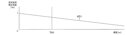
- FIG. 3A is a diagram showing an example of the relationship between the air density correction coefficient and the altitude [m].
- the air density can be obtained based on the atmospheric pressure and the temperature.
- the altitude can be determined based on the air density.
- FIG. 3A in order to facilitate the explanation, the relationship between the air density correction coefficient and the altitude [m] is simplified and shown by the straight line AD1.
- the air density correction coefficient is a value indicating the ratio of the amount of air that can be taken in by the engine 11 when the altitude of the vehicle 1 is 0 m and is set to "1". For example, taking an engine 11 having a maximum output of 100 kW as an example, an engine output of 100 kW is possible when the air density correction coefficient is 1, and an engine output of 90 kW is possible when the air density correction coefficient is 0.9. It is possible. That is, as shown in the straight line AD1, the value of the air density correction coefficient decreases as the altitude of the vehicle 1 increases.
- an example in which the vehicle 1 reaches an altitude of TH1, for example, 2800 m, is determined to be a highland is shown. That is, an example is shown in which the altitude TH1 is set to the highland determination threshold value TH1.
- the high altitude determination threshold value TH1 can be set by using various experimental data such as the performance of the battery, the engine, and the generator according to the altitude.
- FIG. 3B is a diagram showing an example of the relationship between the engine output [kw] and the altitude [m].
- the relationship between the engine output [kw] and the altitude [m] is simplified by a straight line EP1 for the sake of simplicity.
- the engine output according to the altitude can be obtained by multiplying the maximum output of the engine 11 by the air density correction coefficient shown in FIG. 3A. That is, the engine output decreases as the altitude increases.
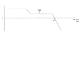
- FIG. 3C is a diagram showing an example of the relationship between the drive output upper limit [kw] of the electric motor 14 and the altitude [m].
- the driving force of the electric motor 14 is not limited. That is, the minimum value of the driving force obtained by the target driving force calculation unit 101 and the torque conversion unit 102 is set as the driving force of the electric motor 14.
- the upper limit of the driving force of the electric motor 14 is limited. Further, the limit amount is gradually increased until the altitude of the vehicle 1 exceeds the highland determination threshold value TH1 and reaches the threshold value TH2 (however, TH1 ⁇ TH2). Further, when the altitude of the vehicle 1 exceeds the threshold value TH2, the limit amount is fixed. By limiting the upper limit of the driving force of the electric motor 14 in this way, it is possible to prevent the SOC of the battery 13 from being overused.
- the kickdown switch when the driver depresses the accelerator with the intention of accelerating, the kickdown switch is turned on. In this case, if the upper limit of the driving force of the electric motor 14 is limited, the driver cannot obtain the intended acceleration feeling, and it is conceivable that the driver feels uncomfortable. Therefore, even when the altitude of the vehicle 1 exceeds the high altitude determination threshold value TH1, when the kickdown switch is turned on, the limitation of the driving force of the electric motor 14 is relaxed as shown in the line DL2 of FIG. 3C.
- the kickdown switch when the kickdown switch is turned on, it is limited by the driving force for kickdown stepping. This makes it possible to reflect the driver's intention to accelerate even in the highlands. Further, the existing kickdown switch can be used to determine the acceleration intention of the driver and used for controlling the limitation of the driving force of the electric motor 14.
- the limit amount of the driving force of the electric motor 14 is set as shown in the line DL3.
- the kickdown switch is turned on, as shown in line DL2, the limit amount of the driving force of the electric motor 14 is set based on the kickdown switch on operation (an example of the acceleration operation of the vehicle 1). Set.
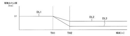
- FIG. 3D is a diagram showing an example of the relationship between the total value [kw] of the engine output and the battery output and the altitude [m].
- the vertical axis in FIG. 3D means the output that can be used by driving the vehicle 1. That is, an example of the relationship when the information regarding the outputs of the engine 11 and the battery 13 is viewed on the power axis is shown.
- the straight line EB1 shown in FIG. 3D indicates a value obtained by adding the value of the straight line EP1 shown in FIG. 3B and the value of the line DL1 shown in FIG. 3C.
- the line EB2 shown in FIG. 3D shows a value obtained by adding the value of the straight line EP1 shown in FIG. 3B and the value of the line DL2 shown in FIG. 3C.
- the line EB3 shown in FIG. 3D shows a value obtained by adding the value of the straight line EP1 shown in FIG. 3B and the value of the line DL3 shown in FIG. 3C.
- the dotted line EB4 shown in FIG. 3D is a case where it is assumed that the limitation shown in FIG. 3C (limitation of the upper limit value of the driving force of the electric motor 14) is not applied when the altitude of the vehicle 1 exceeds the high altitude determination threshold value TH1. Indicates the value of.
- the dotted line BT1 shown in FIG. 3D indicates the amount of electric power generated by the engine output corresponding to the straight line EP1 in FIG. 3B.
- the value of the line EB3 becomes smaller than the value of the dotted line BT1. That is, by limiting the upper limit of the driving force of the electric motor 14, among the electric power that can be generated by the engine output, the amount of electric power that is not used for driving the electric motor 14 is generated. That is, a surplus charge capacity is generated.
- the altitude of the vehicle 1 exceeds the threshold value TH2 and the kickdown switch is not turned on, the electric power generated by the engine output can be charged to the battery 13, and the battery 13 is exhausted. Can be prevented.
- the exhaustion of the battery 13 means that the SOC of the battery 13 is less than a predetermined value. For example, when the SOC of the battery 13 is less than 40%, it is determined that the SOC of the battery 13 is exhausted.
- the battery 13 can be charged by setting the line EB3 below the dotted line BT1. , It is possible to prevent the SOC of the battery 13 from being exhausted.
- the upper limit of the driving force of the electric motor 14 is limited so that the line EB3 is below the dotted line BT1 immediately after the altitude of the vehicle 1 exceeds the high altitude determination threshold TH1, the driving force suddenly increases. There is a risk that such changes will give the driver a sense of discomfort. Therefore, until the altitude of the vehicle 1 exceeds the high altitude determination threshold TH1 and reaches the threshold TH2, as shown in line EB3 of FIG.
- the upper limit of the driving force of the electric motor 14 is set according to the altitude of the vehicle 1. Gradually limit. When the altitude of the vehicle 1 exceeds the threshold value TH2, the upper limit of the driving force of the electric motor 14 is limited so that the line EB3 is below the dotted line BT1.
- the output supply from the battery 13 to the electric motor 14 is not limited according to the amount of depression of the accelerator pedal of the driver. If this is done, the battery 13 may be exhausted immediately. That is, if the engine output is reduced in the highlands but the drive output is unlimited, the SOC of the battery 13 may be exhausted immediately. In this way, when the battery 13 is exhausted, it is necessary to cover the output of the electric motor 14 only with the electric power generated by the engine 11, so that it becomes necessary to remarkably limit the driving force of the electric motor 14, resulting in a feeling of insufficient acceleration. Connect. For example, on highways, such restrictions can lead to driver dissatisfaction.
- the upper limit of the driving force of the electric motor 14 is limited with reference to the highland determination threshold TH1. Further, when the altitude of the vehicle 1 exceeds the highland determination threshold value TH1, the charging capacity is set so as to be generated with reference to the vicinity of the threshold value TH2. That is, when the vehicle 1 has an altitude from the high altitude determination threshold value TH1 to the vicinity of the threshold value TH2, the charging capacity is set so as not to occur, but when the altitude of the vehicle 1 exceeds the threshold value TH2, charging is performed. Set to generate extra power. As described above, in the first embodiment, the control of the driving force of the electric motor 14 and the control of the remaining charging capacity of the battery 13 are changed with reference to the highland determination threshold value TH1 and the threshold value TH2.
- the SOC center of the battery 13 can be changed high in the highlands. Specifically, a charge / discharge map for highlands is prepared, and when it is determined that the map is highlands, the charge / discharge map for highlands is switched to. That is, the SOC target value of the battery 13 is switched from the flat ground to the high ground for use.
- the rotation speed for the highlands and the rotation number of the ⁇ -rays for the highlands are calculated, and the rotation required for the highlands is calculated. Be able to specify the number.
- the driving force of the electric motor 14 is limited and the SOC center of the battery 13 is moved high to achieve the intention of accelerating in the highlands. It is possible to guarantee a tolerable SOC.
- the value of the line EB2 becomes larger than the value of the dotted line BT1 even when the altitude of the vehicle 1 exceeds the threshold value TH2. That is, when the limitation on the upper limit of the driving force of the electric motor 14 is relaxed, the electric power of the battery 13 may be required to drive the electric motor 14 in addition to the electric power generated by the engine output. If such a state continues, the battery 13 may be exhausted. However, when the kickdown switch is not turned on, the driving force of the electric motor 14 is limited, so if the limitation is continued until the driver intends to accelerate, the driver may feel insufficient acceleration. There is. Therefore, when the kickdown switch is turned on, the control as shown by the line EB2 is executed.
- FIG. 4 is a diagram showing an example of the relationship between the required driving force and the vehicle speed.
- the vertical axis indicates the required driving force “N”
- the horizontal axis indicates the vehicle speed “kph”.
- the example of the relationship between the required driving force and the vehicle speed shown in FIG. 4 can also be used as an example of the relationship between the required driving force and the rotation speed of the electric motor 14. I can grasp it.
- Line RD1 shows an example of the relationship between the required driving force and the vehicle speed in an environment that is not determined to be in the highlands.
- the required driving force takes a substantially constant value with respect to the change in the rotation speed of the electric motor 14. Therefore, this region R1 can be referred to as a motor torque constant region.
- this region R2 in which the rotation speed of the electric motor 14 is between the first rotation speed NR1 and the second rotation speed NR2 (however, NR1 ⁇ NR2), the electric motor 14 responds to a change in the rotation speed of the electric motor 14.
- the output of is almost constant. Therefore, this region R2 can be referred to as a motor output constant region.
- the second rotation speed NR2 corresponds to the upper limit rotation speed at which the practical performance of the electric motor 14 can be exhibited.
- Line RD3 shows an example of the relationship between the required driving force and the vehicle speed when the altitude of the vehicle 1 is the high altitude determination threshold value TH1.
- Line RD2 shows an example of the relationship between the required driving force and the vehicle speed when the kickdown switch is turned on when the altitude of the vehicle 1 is the high altitude determination threshold value TH1.
- the driving force is not limited until the vehicle speed reaches S6, regardless of whether or not it is determined to be in the highlands.
- a series-type hybrid vehicle can give a comfortable feeling of acceleration.
- the frequency of depression of the accelerator pedal is often low on expressways, it is considered that the frequency of depression of the accelerator pedal is relatively high in urban areas.
- S6 such as in an urban area
- appropriate acceleration is often required. Therefore, in urban areas where it is expected to travel at relatively low speeds, in order to take advantage of the characteristics of series-type hybrid vehicles, the driving force will not be limited. That is, normal control is performed in an urban area where the vehicle speed is lower than a predetermined vehicle speed.
- S6 is shown as a vehicle speed threshold value TH11
- S8 is shown as a vehicle speed threshold value TH12.
- S6 is a vehicle speed when traveling in an urban area or the like
- S8 is a value about several tens (kph) higher than S6. It should be noted that S6 and S8 can be set by using various experimental data such as the performance of the battery, the engine and the generator according to the altitude and the vehicle speed.
- the driving force is not limited regardless of whether or not it is determined to be in the highlands. Further, in the motor output constant region R2, the driving force is limited when it is determined to be in the highlands.
- the dotted line DD1 indicates the limit value of the driving force of the electric motor 14 when it is determined that the SOC of the battery 13 is exhausted when the altitude of the vehicle 1 is the high altitude determination threshold value TH1. That is, the dotted line DD1 is a driving force for driving the electric motor 14 using only the electric power generated by the engine output when it is determined that the SOC of the battery 13 is exhausted and the electric power of the battery 13 cannot be used. Is shown.
- the driving force of the electric motor 14 is secured up to the value of the dotted line DD1. It is possible. Further, by setting the relationship between the required driving force of the vehicle 1 and the vehicle speed below the dotted line DD1, the electric power generated by the engine output can be charged to the battery 13.
- the driving force of the electric motor 14 is limited based on the electric power generated by the engine 11 in that environment. In other words, the driving force of the electric motor 14 is limited so that the electric power generated by the engine 11 in the environment becomes larger than the required power of the electric motor 14.
- the battery 13 can be charged by setting the relationship between the required driving force of the vehicle 1 and the vehicle speed below the dotted line DD1. Therefore, it is possible to prevent the SOC of the battery 13 from being exhausted.
- the driving force of the electric motor 14 is limited so as to be below the dotted line DD1 immediately after the vehicle speed exceeds the vehicle speed threshold value TH11, a sudden change in the driving force gives the driver a sense of discomfort. There is a risk.
- the driving force of the electric motor 14 is gradually limited according to the increase in the vehicle speed, as shown by the line RD3 in FIG. Then, when the vehicle speed exceeds the vehicle speed threshold value TH12, the driving force of the electric motor 14 is limited so that the line RD3 is lower than the dotted line DD1.
- the driving force of the electric motor 14 is limited based on the vehicle speed of the vehicle 1 as shown in the lines RD2 and RD3. Set the amount. Further, as shown in the line RD2, the limit amount of the driving force of the electric motor 14 is set based on the vehicle speed of the vehicle 1 and the acceleration operation of the vehicle 1 (on operation of the kickdown switch).
- FIG. 5 is a flowchart showing an example of a processing procedure of vehicle control processing executed by the control system of vehicle 1. It should be noted that this processing procedure is executed based on the program stored in the storage unit (not shown) of the control system of the vehicle 1.
- step S501 the highland determination unit 103 and the highland determination unit 202 perform highland determination. If it is determined to be in the highlands, the process proceeds to step S505, and if it is determined to be not in the highlands, the process proceeds to step S502.
- the power generation system controller 200 sets the target SOC center at the normal time.
- the map selection unit 205 selects the normal time charge / discharge map held in the normal time charge / discharge map holding unit 203, and the charge / discharge of the battery 13 based on the normal time charge / discharge map is set.
- the target SOC center in the normal time means the SOC center (the SOC in which the additional charge amount is 0 kW) that is the target in the normal time.
- step S503 the power generation system controller 200 sets the normal engine speed.
- the ⁇ -ray rotation speed calculation unit 208 calculates the rotation speed of the ⁇ -ray based on the normal time charge / discharge map. Further, the rotation speed selection unit 211 selects "0". Then, the maximum value selection unit 212 is the smaller of the value selected by the minimum value selection unit 209 (the rotation speed of the ⁇ ray based on the normal time charge / discharge map and the optimum rotation speed according to the vehicle speed of the vehicle 1). Value) is selected as the engine speed.
- step S504 the drive system controller 100 outputs an instruction for controlling the driving force of the vehicle 1 to the inverter 15 based on the value selected by the selection unit 106. Since it is not determined to be a highland, the selection unit 106 selects the minimum value of the driving force obtained by the target driving force calculation unit 101 and the torque conversion unit 102.
- step S505 the power generation system controller 200 sets the target SOC center for highlands.
- the map selection unit 205 selects the highland charge / discharge map held in the highland charge / discharge map holding unit 204, and the charge / discharge of the battery 13 based on the highland charge / discharge map is set.
- the target SOC center for highlands means the target SOC center (SOC with an additional charge amount of 0 kW) when it is determined to be in the highlands.
- the target SOC center of the battery 13 is set to a larger value than before it is determined to be in the highlands.
- step S506 the power generation system controller 200 sets the engine speed for highlands.
- the ⁇ -ray rotation speed calculation unit 208 calculates the rotation speed of the ⁇ -ray based on the high-altitude charge / discharge map.
- the minimum value selection unit 209 selects a smaller value of the rotation speed of the ⁇ ray based on the charge / discharge map for highlands and the optimum rotation speed according to the vehicle speed of the vehicle 1.
- the rotation speed selection unit 211 selects the rotation speed of the engine 11 for high altitudes calculated by the rotation speed calculation unit 210 for high altitudes.
- the maximum value selection unit 212 rotates the engine with a larger value from the value selected by the minimum value selection unit 209 and the value selected by the rotation speed selection unit 211 (the rotation speed of the engine 11 for highlands). Select as a number.
- step S507 the K / D determination unit 104 makes a K / D determination to determine whether or not the kickdown switch is turned on. Then, when the kickdown switch is turned on, the process proceeds to step S509, and when the kickdown switch is not turned on, the process proceeds to step S508.
- step S508 the drive torque limiting unit 105 sets a limit value for the driving force for highlands. Specifically, as shown in the line DL3 of FIG. 3C and the line RD3 of FIG. 4, the limit value of the driving force for highlands is set.
- step S509 the drive torque limiting unit 105 sets the driving force limit for highlands by a predetermined value. Specifically, as shown in the line DL2 of FIG. 3C and the line RD2 of FIG. 4, the limit value of the driving force for highlands when the kickdown switch is turned on is set.
- step S510 the selection unit 106 determines the vehicle speed to determine whether or not the vehicle speed is equal to or higher than a predetermined value. Then, when the vehicle speed is equal to or higher than a predetermined value, the selection unit 106 selects the limit value of the driving force for highlands set by the drive torque limiting unit 105 in step S508 or S509, and proceeds to step S508. However, when the value set by the drive torque limiting unit 105 is larger than the value obtained by the target driving force calculation unit 101 or the torque conversion unit 102, it is obtained by the target driving force calculation unit 101 and the torque conversion unit 102. The minimum value of the applied driving force is selected. On the other hand, when the vehicle speed is less than a predetermined value, the selection unit 106 selects the minimum value of the driving force obtained by the target driving force calculation unit 101 and the torque conversion unit 102, and proceeds to step S504.
- the driving force is not limited even if it is determined to be in the highlands.
- a predetermined value for example, S6 (kph) shown in FIG. 4
- the target SOC center for the highlands is set and the engine speed for the highlands is set.
- step S511 the drive system controller 100 outputs an instruction for controlling the driving force of the vehicle 1 to the inverter 15 based on the value selected by the selection unit 106.
- the electric power generated by the engine is used to increase the SOC of the battery.
- a part of the electric power generated by the engine is used to increase the SOC of the battery, so that the electric power used as the driving force for driving the electric motor is limited. That is, since the SOC of the battery is increased, the driving force of the vehicle is further limited.
- the driving force of the vehicle is significantly limited, the driving force of the vehicle is significantly different before and after the SOC of the battery is lowered, so that the driver may feel dissatisfied.
- the control that limits the driving force of the vehicle 1 is executed even when the SOC of the battery 13 is not lowered. That is, when it is determined that the altitude is high, the control for limiting the driving force of the vehicle 1 is executed regardless of the SOC of the battery 13.
- the driving force of the electric motor 14 when it is determined that the altitude is high and there is no intention of acceleration (that is, when the kickdown switch is not turned on), the driving force of the electric motor 14 is limited.
- the limitation on the driving force of the electric motor 14 when it is determined to be a highland and there is an intention to accelerate (that is, when the kickdown switch is turned on), the limitation on the driving force of the electric motor 14 is relaxed. By doing so, it is possible to extend the time until the vehicle becomes in a low SOC state that significantly limits the driving force of the vehicle 1 while responding to the driver's acceleration intention, and to extend the distance (time) that can be traveled at high output. Can be done.
- the driving force of the electric motor 14 can be limited as the engine output decreases. Further, the SOC of the battery 13 can be preserved by limiting the driving force of the electric motor 14. Further, by switching to the charge / discharge map for highlands and calculating the engine speed for highlands, the SOC center of the battery 13 can be changed to a higher value. Further, it is possible to determine whether or not the driver intends to accelerate, and when the driver intends to accelerate, the limitation on the driving force of the electric motor 14 can be relaxed. As a result, when the vehicle 1 is present in a high altitude, it is possible to control the minimum vehicle speed to continue for a long time by depressing the accelerator pedal while suppressing a decrease in the SOC of the battery 13.
- the vehicle control method according to the first embodiment is configured to be rechargeable by an electric motor 14 for driving the vehicle 1, an engine 11 for driving a generator 12 for generating electric power to be supplied to the electric motor 14, and a generator 12. It is a control method of the vehicle 1 including the battery 13 electrically connected to the electric motor 14 as well as the electric motor 14.
- This control method includes a control step (steps S505 to S511) for limiting the driving force of the electric motor 14 when the vehicle 1 is traveling in an environment where the output of the engine 11 is limited.
- the decrease in the SOC of the battery 13 is suppressed by limiting the driving force of the electric motor 14 in response to the decrease in the engine output in the highlands, and the mileage of the vehicle 1 is suppressed. Can be extended.
- control steps S510, S511) are based on the vehicle speed of the vehicle 1 when the vehicle 1 is traveling in an environment in which the output of the engine 11 is restricted.
- the limit amount of the driving force of the electric motor 14 is set.
- the driving force of the electric motor 14 can be adjusted based on the vehicle speed of the vehicle 1 to provide a comfortable operating environment for the driver.
- the vehicle speed of the vehicle 1 is predetermined when the vehicle 1 is traveling in an environment where the output of the engine 11 is restricted.
- the value for example, S6 (kph) shown in FIG. 4
- the driving force of the electric motor 14 is limited, and when the vehicle speed of the vehicle 1 is small based on the predetermined value, the driving force of the electric motor 14 is not limited.
- the driving force of the electric motor 14 is not limited in an urban area or the like where the vehicle is expected to travel at a low speed, and the electric motor 14 is driven on a highway or the like where the vehicle is expected to travel at a high speed. Limit power. In this way, the driving force of the electric motor 14 can be adjusted based on the vehicle speed of the vehicle 1.
- the vehicle 1 in the control step (steps S507 and S509), the vehicle 1 travels in an environment where the output of the engine 11 is restricted, and the vehicle speed of the vehicle 1 is set to a predetermined value.
- the kickdown switch is turned on (an example of a predetermined acceleration operation) in a large case as a reference, the limitation on the driving force of the electric motor 14 is relaxed.
- control step is a kickdown switch of the vehicle 1 when the vehicle 1 is traveling in an environment where the output of the engine 11 is restricted.
- the limit amount of the driving force of the electric motor 14 is set based on the on operation (an example of a predetermined acceleration operation).
- control steps S507 to S511) are the vehicle speed of the vehicle 1 and the vehicle when the vehicle 1 is traveling in an environment where the output of the engine 11 is restricted.
- the limit amount of the driving force of the electric motor 14 is set based on the acceleration operation of 1.
- step S505 when the vehicle 1 is traveling in an environment in which the output of the engine 11 is restricted, the vehicle 1 travels in that environment.
- the SOC in which the additional charge amount of the battery 13 is 0 kW is set to a larger value than before. That is, the target SOC center of the battery 13 is set higher than before the vehicle 1 travels in the environment.
- the SOC in which the additional charge amount of the battery 13 is 0 kW is So1 shown in FIG. 2A and So2 shown in FIG. 2B, and is also referred to as a SOC center.
- the driving force of the electric motor 14 is limited in accordance with the decrease in the engine output in the highlands, and at the same time, the SOC of the battery 13 is limited. Control the center higher.
- step S508 when the vehicle 1 is traveling in an environment in which the output of the engine 11 is restricted, the engine 11 is in that environment.
- the driving force of the electric motor 14 is limited based on the power generated by the electric motor 14.
- the SOC of the battery 13 is set by setting the output value of the electric motor 14 based on the maximum output value of the engine 11 in high altitudes. It is possible to suppress the decrease in the vehicle 1 and extend the mileage of the vehicle 1.
- step S508 the electric power generated by the engine 11 in an environment where the output of the engine 11 is limited becomes larger than the required power of the electric motor 14. As such, the driving force of the electric motor 14 is limited.
- the amount of power generated by the engine 11 decreases in high altitudes. Therefore, by setting the output value of the electric motor 14 smaller than the maximum output value of the engine 11 in high altitudes, the SOC of the battery 13 can be determined. It is possible to suppress the decrease and extend the mileage of the vehicle 1.
- control step is the output of the electric motor 14 when the vehicle 1 is traveling in an environment where the output of the engine 11 is restricted. Limit the driving force in a certain area.
- a comfortable operating environment can be provided to the driver by adjusting the driving force of the electric motor 14 in a constant output region.
- the control system of the vehicle 1 can be charged by the electric motor 14 that drives the vehicle 1, the engine 11 that drives the generator 12 that generates the electric power supplied to the electric motor 14, and the generator 12. It includes a battery 13 that is configured and electrically connected to the electric motor 14, and a drive system controller 100 (an example of the controller) that controls the electric motor 14.
- the drive system controller 100 limits the driving force of the electric motor 14 when the vehicle 1 is traveling in an environment where the output of the engine 11 is limited.
- the decrease in the SOC of the battery 13 is suppressed by limiting the driving force of the electric motor 14 in response to the decrease in the engine output in the highlands, and the vehicle 1 travels. You can extend the distance.
- the upper limit value of the driving force of the electric motor is limited when the altitude of the vehicle exceeds the high altitude determination threshold value TH1. That is, an example is shown in which control is performed in one step when it is determined to be a highland. However, a plurality of high altitude determination threshold values may be set, and restrictions corresponding to each high altitude determination threshold value may be executed at the timing when the altitude of the vehicle exceeds these high altitude determination threshold values. Therefore, in the second embodiment, an example is shown in which a plurality of high altitude determination threshold values are set to limit the upper limit value of the driving force of the electric motor.
- the second embodiment is an example in which a part of the first embodiment is modified, and the illustration and a part of the description thereof are omitted for the parts common to the first embodiment.
- FIG. 6 is a diagram showing an example of the relationship between the required driving force and the vehicle speed in the second embodiment. Note that FIG. 6 is an example in which a part of FIG. 4 is modified, and the parts common to FIG. 4 are designated by the same reference numerals and a part of the description thereof will be omitted.
- a high altitude determination threshold value TH1 for example, about 2800 m
- a high altitude determination threshold value TH3 for example, about 2300 m
- Line RD5 shows an example of the relationship between the required driving force and the vehicle speed when the altitude of the vehicle 1 is the high altitude determination threshold value TH3.
- Line RD4 shows an example of the relationship between the required driving force and the vehicle speed when the kickdown switch is turned on when the altitude of the vehicle 1 is the high altitude determination threshold value TH3.
- the limit value when the altitude of the vehicle 1 is the high altitude determination threshold value TH3 is smaller than the limit value when the altitude of the vehicle 1 is the high altitude determination threshold value TH1.
- the vehicle 1 equipped with the kickdown switch has been described as an example.
- the first and second embodiments can be applied to a vehicle not equipped with a kickdown switch. Therefore, in the third embodiment, a vehicle not equipped with a kickdown switch will be described as an example.
- the third embodiment is an example in which a part of the first and second embodiments is modified, and the illustration and a part of the description thereof are omitted for the parts common to the first and second embodiments.
- the vehicle in the third embodiment omits the K / D determination unit 104 shown in FIG. Further, in the third embodiment, when the driving force of the electric motor 14 is limited, the limitation is not relaxed in consideration of the kickdown switch. Specifically, the limit values corresponding to the line DL2 shown in FIG. 3C, the EB2 shown in FIG. 3D, the line RD2 shown in FIG. 4, and the line RD4 shown in FIG. 6 are not selected. Therefore, it is possible to further suppress the decrease in SOC of the battery 13 and further extend the mileage of the vehicle 1.
- FIG. 7 is a flowchart showing an example of a processing procedure of the vehicle control process executed by the vehicle control system according to the third embodiment.
- the example shown in FIG. 7 is a modification of a part of FIG. 5, and the same reference numerals are given to the parts common to those in FIG. 5, and a part of the description thereof will be omitted.
- FIG. 7 is different in that steps S507 and S509 shown in FIG. 5 are omitted.
- the decrease in the SOC of the battery 13 is further suppressed, and the mileage of the vehicle 1 is increased. It can be extended further.
Landscapes
- Engineering & Computer Science (AREA)
- Transportation (AREA)
- Mechanical Engineering (AREA)
- Automation & Control Theory (AREA)
- Chemical & Material Sciences (AREA)
- Combustion & Propulsion (AREA)
- Human Computer Interaction (AREA)
- Physics & Mathematics (AREA)
- Mathematical Physics (AREA)
- Electric Propulsion And Braking For Vehicles (AREA)
- Hybrid Electric Vehicles (AREA)
- Control Of Vehicle Engines Or Engines For Specific Uses (AREA)
Priority Applications (7)
| Application Number | Priority Date | Filing Date | Title |
|---|---|---|---|
| US18/018,004 US12286093B2 (en) | 2020-07-28 | 2020-07-28 | Method for controlling vehicle and system for controlling vehicle |
| MX2023001110A MX2023001110A (es) | 2020-07-28 | 2020-07-28 | Metodo para controlar vehiculo y sistema para controlar vehiculo. |
| CN202080104633.0A CN116133918B (zh) | 2020-07-28 | 2020-07-28 | 车辆的控制方法以及车辆的控制系统 |
| JP2022539842A JP7323073B2 (ja) | 2020-07-28 | 2020-07-28 | 車両の制御方法及び車両の制御システム |
| BR112023001526A BR112023001526A2 (pt) | 2020-07-28 | 2020-07-28 | Método para controlar veículo e sistema para controlar veículo |
| PCT/JP2020/028930 WO2022024228A1 (ja) | 2020-07-28 | 2020-07-28 | 車両の制御方法及び車両の制御システム |
| EP20947167.1A EP4190653B1 (en) | 2020-07-28 | 2020-07-28 | Method for controlling vehicle and system for controlling vehicle |
Applications Claiming Priority (1)
| Application Number | Priority Date | Filing Date | Title |
|---|---|---|---|
| PCT/JP2020/028930 WO2022024228A1 (ja) | 2020-07-28 | 2020-07-28 | 車両の制御方法及び車両の制御システム |
Publications (1)
| Publication Number | Publication Date |
|---|---|
| WO2022024228A1 true WO2022024228A1 (ja) | 2022-02-03 |
Family
ID=80037850
Family Applications (1)
| Application Number | Title | Priority Date | Filing Date |
|---|---|---|---|
| PCT/JP2020/028930 Ceased WO2022024228A1 (ja) | 2020-07-28 | 2020-07-28 | 車両の制御方法及び車両の制御システム |
Country Status (7)
| Country | Link |
|---|---|
| US (1) | US12286093B2 (https=) |
| EP (1) | EP4190653B1 (https=) |
| JP (1) | JP7323073B2 (https=) |
| CN (1) | CN116133918B (https=) |
| BR (1) | BR112023001526A2 (https=) |
| MX (1) | MX2023001110A (https=) |
| WO (1) | WO2022024228A1 (https=) |
Families Citing this family (2)
| Publication number | Priority date | Publication date | Assignee | Title |
|---|---|---|---|---|
| JP7211536B2 (ja) * | 2019-12-06 | 2023-01-24 | 日産自動車株式会社 | ハイブリッド車両制御方法及びハイブリッド車両制御装置 |
| US20250360929A1 (en) * | 2024-05-24 | 2025-11-27 | Thermo King Llc | Auxiliary power unit power compensation using global positioning system for altitude |
Citations (9)
| Publication number | Priority date | Publication date | Assignee | Title |
|---|---|---|---|---|
| JP2009173235A (ja) * | 2008-01-28 | 2009-08-06 | Toyota Motor Corp | ハイブリッド車両の駆動力制御装置 |
| JP2009220765A (ja) * | 2008-03-18 | 2009-10-01 | Toyota Motor Corp | ハイブリッド車両の制御装置 |
| JP2012060844A (ja) * | 2010-09-13 | 2012-03-22 | Toyota Motor Corp | 車両 |
| JP2014133457A (ja) | 2013-01-09 | 2014-07-24 | Mitsubishi Motors Corp | ハイブリッド車のエンジン運転制御装置 |
| JP2015093573A (ja) * | 2013-11-12 | 2015-05-18 | トヨタ自動車株式会社 | ハイブリッド車両 |
| JP2015209027A (ja) * | 2014-04-24 | 2015-11-24 | 三菱自動車工業株式会社 | ハイブリッド車両の制御装置 |
| JP2019123378A (ja) * | 2018-01-17 | 2019-07-25 | トヨタ自動車株式会社 | シリーズハイブリッド車両の制御装置 |
| JP2020011649A (ja) * | 2018-07-19 | 2020-01-23 | 本田技研工業株式会社 | ハイブリッド車両の制御装置 |
| JP2020089031A (ja) * | 2018-11-22 | 2020-06-04 | マツダ株式会社 | 車両の電源制御装置 |
Family Cites Families (7)
| Publication number | Priority date | Publication date | Assignee | Title |
|---|---|---|---|---|
| ES2167809T5 (es) * | 1996-12-20 | 2013-06-20 | Manuel Dos Santos Da Ponte | Aparato generador híbrido |
| JP3374802B2 (ja) * | 1999-09-24 | 2003-02-10 | 株式会社日立製作所 | ハイブリッド車両 |
| US11254211B2 (en) * | 2005-11-17 | 2022-02-22 | Invently Automotive Inc. | Electric vehicle power management system |
| JP5332907B2 (ja) * | 2009-05-27 | 2013-11-06 | 日産自動車株式会社 | 電動車両のバッテリ充電制御装置 |
| US8973536B2 (en) * | 2013-01-25 | 2015-03-10 | Caterpillar Inc. | Engine compensation for fan power |
| JP5928493B2 (ja) | 2014-01-17 | 2016-06-01 | トヨタ自動車株式会社 | 車両 |
| JP7053279B2 (ja) * | 2018-01-15 | 2022-04-12 | 本田技研工業株式会社 | 車両制御システム、車両制御方法、およびプログラム |
-
2020
- 2020-07-28 BR BR112023001526A patent/BR112023001526A2/pt not_active Application Discontinuation
- 2020-07-28 US US18/018,004 patent/US12286093B2/en active Active
- 2020-07-28 EP EP20947167.1A patent/EP4190653B1/en active Active
- 2020-07-28 JP JP2022539842A patent/JP7323073B2/ja active Active
- 2020-07-28 MX MX2023001110A patent/MX2023001110A/es unknown
- 2020-07-28 CN CN202080104633.0A patent/CN116133918B/zh active Active
- 2020-07-28 WO PCT/JP2020/028930 patent/WO2022024228A1/ja not_active Ceased
Patent Citations (9)
| Publication number | Priority date | Publication date | Assignee | Title |
|---|---|---|---|---|
| JP2009173235A (ja) * | 2008-01-28 | 2009-08-06 | Toyota Motor Corp | ハイブリッド車両の駆動力制御装置 |
| JP2009220765A (ja) * | 2008-03-18 | 2009-10-01 | Toyota Motor Corp | ハイブリッド車両の制御装置 |
| JP2012060844A (ja) * | 2010-09-13 | 2012-03-22 | Toyota Motor Corp | 車両 |
| JP2014133457A (ja) | 2013-01-09 | 2014-07-24 | Mitsubishi Motors Corp | ハイブリッド車のエンジン運転制御装置 |
| JP2015093573A (ja) * | 2013-11-12 | 2015-05-18 | トヨタ自動車株式会社 | ハイブリッド車両 |
| JP2015209027A (ja) * | 2014-04-24 | 2015-11-24 | 三菱自動車工業株式会社 | ハイブリッド車両の制御装置 |
| JP2019123378A (ja) * | 2018-01-17 | 2019-07-25 | トヨタ自動車株式会社 | シリーズハイブリッド車両の制御装置 |
| JP2020011649A (ja) * | 2018-07-19 | 2020-01-23 | 本田技研工業株式会社 | ハイブリッド車両の制御装置 |
| JP2020089031A (ja) * | 2018-11-22 | 2020-06-04 | マツダ株式会社 | 車両の電源制御装置 |
Non-Patent Citations (1)
| Title |
|---|
| See also references of EP4190653A4 |
Also Published As
| Publication number | Publication date |
|---|---|
| JP7323073B2 (ja) | 2023-08-08 |
| JPWO2022024228A1 (https=) | 2022-02-03 |
| EP4190653B1 (en) | 2025-08-27 |
| CN116133918A (zh) | 2023-05-16 |
| EP4190653A4 (en) | 2023-09-06 |
| BR112023001526A2 (pt) | 2023-02-14 |
| EP4190653A1 (en) | 2023-06-07 |
| US20230271598A1 (en) | 2023-08-31 |
| MX2023001110A (es) | 2023-02-22 |
| US12286093B2 (en) | 2025-04-29 |
| CN116133918B (zh) | 2025-09-19 |
Similar Documents
| Publication | Publication Date | Title |
|---|---|---|
| CN103249624B (zh) | 混合动力系统控制装置 | |
| JP2012066624A (ja) | 電動車両の発電制御装置両 | |
| CN112109698B (zh) | 车辆控制方法、装置、介质及车辆 | |
| KR102703754B1 (ko) | 친환경 차량의 연료 전지 제어 장치, 그를 포함한 시스템 및 그 방법 | |
| CN104554266B (zh) | 具有踏板位置对车轮输出需求的动态映射的混合动力车辆 | |
| WO2007141984A1 (ja) | ハイブリッド車両の制御装置およびハイブリッド車両 | |
| JP2014519432A (ja) | 内燃機関制御装置及び内燃機関制御方法 | |
| US20150066327A1 (en) | Eco-mode cruise control | |
| US7684906B2 (en) | Method of controlling hybrid vehicle | |
| US11535237B2 (en) | Electric device control method and electric device | |
| JPWO2011125865A1 (ja) | ハイブリッド車両の制御装置 | |
| JP7323073B2 (ja) | 車両の制御方法及び車両の制御システム | |
| JP3662904B2 (ja) | ハイブリッド車両の駆動制御システム | |
| US9434378B2 (en) | System and method for improving the vehicle feel, fuel efficiency and performance of a hybrid vehicle | |
| JP2015166220A (ja) | ハイブリッド車の制御装置 | |
| JP7115647B2 (ja) | 電動車両の制御装置 | |
| US11420615B2 (en) | Powertrain system | |
| JP2019206956A (ja) | 車両システム | |
| KR102873158B1 (ko) | 하이브리드 자동차 및 그를 위한 동력 제어 방법 | |
| JP5927792B2 (ja) | 車両用制御装置および車両用制御方法 | |
| WO2025248656A1 (ja) | 車両の制御方法および車両の制御装置 | |
| JP2023060622A (ja) | 制御装置およびハイブリッド車両 | |
| CN118251337B (zh) | 车辆的控制方法以及车辆的控制装置 | |
| JP2020075534A (ja) | ハイブリッド車両の制御装置 | |
| JP2019018691A (ja) | ハイブリッド車両の制御装置 |
Legal Events
| Date | Code | Title | Description |
|---|---|---|---|
| 121 | Ep: the epo has been informed by wipo that ep was designated in this application |
Ref document number: 20947167 Country of ref document: EP Kind code of ref document: A1 |
|
| ENP | Entry into the national phase |
Ref document number: 2022539842 Country of ref document: JP Kind code of ref document: A |
|
| REG | Reference to national code |
Ref country code: BR Ref legal event code: B01A Ref document number: 112023001526 Country of ref document: BR |
|
| ENP | Entry into the national phase |
Ref document number: 112023001526 Country of ref document: BR Kind code of ref document: A2 Effective date: 20230126 |
|
| WWE | Wipo information: entry into national phase |
Ref document number: 2020947167 Country of ref document: EP |
|
| ENP | Entry into the national phase |
Ref document number: 2020947167 Country of ref document: EP Effective date: 20230228 |
|
| NENP | Non-entry into the national phase |
Ref country code: DE |
|
| WWG | Wipo information: grant in national office |
Ref document number: 18018004 Country of ref document: US |
|
| WWG | Wipo information: grant in national office |
Ref document number: 2020947167 Country of ref document: EP |
|
| WWG | Wipo information: grant in national office |
Ref document number: 202080104633.0 Country of ref document: CN |