WO2022018948A1 - 製袋方法、および、溶着方法 - Google Patents
製袋方法、および、溶着方法 Download PDFInfo
- Publication number
- WO2022018948A1 WO2022018948A1 PCT/JP2021/019009 JP2021019009W WO2022018948A1 WO 2022018948 A1 WO2022018948 A1 WO 2022018948A1 JP 2021019009 W JP2021019009 W JP 2021019009W WO 2022018948 A1 WO2022018948 A1 WO 2022018948A1
- Authority
- WO
- WIPO (PCT)
- Prior art keywords
- horn
- anvil
- gusset
- torso
- bag
- Prior art date
- Legal status (The legal status is an assumption and is not a legal conclusion. Google has not performed a legal analysis and makes no representation as to the accuracy of the status listed.)
- Ceased
Links
Images


Classifications
-
- B—PERFORMING OPERATIONS; TRANSPORTING
- B31—MAKING ARTICLES OF PAPER, CARDBOARD OR MATERIAL WORKED IN A MANNER ANALOGOUS TO PAPER; WORKING PAPER, CARDBOARD OR MATERIAL WORKED IN A MANNER ANALOGOUS TO PAPER
- B31B—MAKING CONTAINERS OF PAPER, CARDBOARD OR MATERIAL WORKED IN A MANNER ANALOGOUS TO PAPER
- B31B70/00—Making flexible containers, e.g. envelopes or bags
- B31B70/60—Uniting opposed surfaces or edges; Taping
- B31B70/64—Uniting opposed surfaces or edges; Taping by applying heat or pressure
- B31B70/644—Making seals parallel to the direction of movement, i.e. longitudinal sealing
-
- B—PERFORMING OPERATIONS; TRANSPORTING
- B31—MAKING ARTICLES OF PAPER, CARDBOARD OR MATERIAL WORKED IN A MANNER ANALOGOUS TO PAPER; WORKING PAPER, CARDBOARD OR MATERIAL WORKED IN A MANNER ANALOGOUS TO PAPER
- B31B—MAKING CONTAINERS OF PAPER, CARDBOARD OR MATERIAL WORKED IN A MANNER ANALOGOUS TO PAPER
- B31B70/00—Making flexible containers, e.g. envelopes or bags
- B31B70/60—Uniting opposed surfaces or edges; Taping
- B31B70/64—Uniting opposed surfaces or edges; Taping by applying heat or pressure
- B31B70/645—Making seals transversally to the direction of movement
-
- B—PERFORMING OPERATIONS; TRANSPORTING
- B29—WORKING OF PLASTICS; WORKING OF SUBSTANCES IN A PLASTIC STATE IN GENERAL
- B29C—SHAPING OR JOINING OF PLASTICS; SHAPING OF MATERIAL IN A PLASTIC STATE, NOT OTHERWISE PROVIDED FOR; AFTER-TREATMENT OF THE SHAPED PRODUCTS, e.g. REPAIRING
- B29C65/00—Joining or sealing of preformed parts, e.g. welding of plastics materials; Apparatus therefor
- B29C65/02—Joining or sealing of preformed parts, e.g. welding of plastics materials; Apparatus therefor by heating, with or without pressure
- B29C65/08—Joining or sealing of preformed parts, e.g. welding of plastics materials; Apparatus therefor by heating, with or without pressure using ultrasonic vibrations
-
- B—PERFORMING OPERATIONS; TRANSPORTING
- B29—WORKING OF PLASTICS; WORKING OF SUBSTANCES IN A PLASTIC STATE IN GENERAL
- B29C—SHAPING OR JOINING OF PLASTICS; SHAPING OF MATERIAL IN A PLASTIC STATE, NOT OTHERWISE PROVIDED FOR; AFTER-TREATMENT OF THE SHAPED PRODUCTS, e.g. REPAIRING
- B29C65/00—Joining or sealing of preformed parts, e.g. welding of plastics materials; Apparatus therefor
- B29C65/74—Joining or sealing of preformed parts, e.g. welding of plastics materials; Apparatus therefor by welding and severing, or by joining and severing, the severing being performed in the area to be joined, next to the area to be joined, in the joint area or next to the joint area
-
- B—PERFORMING OPERATIONS; TRANSPORTING
- B29—WORKING OF PLASTICS; WORKING OF SUBSTANCES IN A PLASTIC STATE IN GENERAL
- B29C—SHAPING OR JOINING OF PLASTICS; SHAPING OF MATERIAL IN A PLASTIC STATE, NOT OTHERWISE PROVIDED FOR; AFTER-TREATMENT OF THE SHAPED PRODUCTS, e.g. REPAIRING
- B29C65/00—Joining or sealing of preformed parts, e.g. welding of plastics materials; Apparatus therefor
- B29C65/78—Means for handling the parts to be joined, e.g. for making containers or hollow articles, e.g. means for handling sheets, plates, web-like materials, tubular articles, hollow articles or elements to be joined therewith; Means for discharging the joined articles from the joining apparatus
- B29C65/7858—Means for handling the parts to be joined, e.g. for making containers or hollow articles, e.g. means for handling sheets, plates, web-like materials, tubular articles, hollow articles or elements to be joined therewith; Means for discharging the joined articles from the joining apparatus characterised by the feeding movement of the parts to be joined
- B29C65/7888—Means for handling of moving sheets or webs
- B29C65/7891—Means for handling of moving sheets or webs of discontinuously moving sheets or webs
-
- B—PERFORMING OPERATIONS; TRANSPORTING
- B29—WORKING OF PLASTICS; WORKING OF SUBSTANCES IN A PLASTIC STATE IN GENERAL
- B29C—SHAPING OR JOINING OF PLASTICS; SHAPING OF MATERIAL IN A PLASTIC STATE, NOT OTHERWISE PROVIDED FOR; AFTER-TREATMENT OF THE SHAPED PRODUCTS, e.g. REPAIRING
- B29C66/00—General aspects of processes or apparatus for joining preformed parts
- B29C66/01—General aspects dealing with the joint area or with the area to be joined
- B29C66/03—After-treatments in the joint area
- B29C66/032—Mechanical after-treatments
- B29C66/0326—Cutting, e.g. by using waterjets, or perforating
-
- B—PERFORMING OPERATIONS; TRANSPORTING
- B29—WORKING OF PLASTICS; WORKING OF SUBSTANCES IN A PLASTIC STATE IN GENERAL
- B29C—SHAPING OR JOINING OF PLASTICS; SHAPING OF MATERIAL IN A PLASTIC STATE, NOT OTHERWISE PROVIDED FOR; AFTER-TREATMENT OF THE SHAPED PRODUCTS, e.g. REPAIRING
- B29C66/00—General aspects of processes or apparatus for joining preformed parts
- B29C66/01—General aspects dealing with the joint area or with the area to be joined
- B29C66/05—Particular design of joint configurations
- B29C66/10—Particular design of joint configurations particular design of the joint cross-sections
- B29C66/11—Joint cross-sections comprising a single joint-segment, i.e. one of the parts to be joined comprising a single joint-segment in the joint cross-section
- B29C66/112—Single lapped joints
- B29C66/1122—Single lap to lap joints, i.e. overlap joints
-
- B—PERFORMING OPERATIONS; TRANSPORTING
- B29—WORKING OF PLASTICS; WORKING OF SUBSTANCES IN A PLASTIC STATE IN GENERAL
- B29C—SHAPING OR JOINING OF PLASTICS; SHAPING OF MATERIAL IN A PLASTIC STATE, NOT OTHERWISE PROVIDED FOR; AFTER-TREATMENT OF THE SHAPED PRODUCTS, e.g. REPAIRING
- B29C66/00—General aspects of processes or apparatus for joining preformed parts
- B29C66/40—General aspects of joining substantially flat articles, e.g. plates, sheets or web-like materials; Making flat seams in tubular or hollow articles; Joining single elements to substantially flat surfaces
- B29C66/41—Joining substantially flat articles ; Making flat seams in tubular or hollow articles
- B29C66/43—Joining a relatively small portion of the surface of said articles
- B29C66/431—Joining the articles to themselves
-
- B—PERFORMING OPERATIONS; TRANSPORTING
- B29—WORKING OF PLASTICS; WORKING OF SUBSTANCES IN A PLASTIC STATE IN GENERAL
- B29C—SHAPING OR JOINING OF PLASTICS; SHAPING OF MATERIAL IN A PLASTIC STATE, NOT OTHERWISE PROVIDED FOR; AFTER-TREATMENT OF THE SHAPED PRODUCTS, e.g. REPAIRING
- B29C66/00—General aspects of processes or apparatus for joining preformed parts
- B29C66/70—General aspects of processes or apparatus for joining preformed parts characterised by the composition, physical properties or the structure of the material of the parts to be joined; Joining with non-plastics material
- B29C66/72—General aspects of processes or apparatus for joining preformed parts characterised by the composition, physical properties or the structure of the material of the parts to be joined; Joining with non-plastics material characterised by the structure of the material of the parts to be joined
- B29C66/723—General aspects of processes or apparatus for joining preformed parts characterised by the composition, physical properties or the structure of the material of the parts to be joined; Joining with non-plastics material characterised by the structure of the material of the parts to be joined being multi-layered
- B29C66/7232—General aspects of processes or apparatus for joining preformed parts characterised by the composition, physical properties or the structure of the material of the parts to be joined; Joining with non-plastics material characterised by the structure of the material of the parts to be joined being multi-layered comprising a non-plastics layer
- B29C66/72327—General aspects of processes or apparatus for joining preformed parts characterised by the composition, physical properties or the structure of the material of the parts to be joined; Joining with non-plastics material characterised by the structure of the material of the parts to be joined being multi-layered comprising a non-plastics layer consisting of natural products or their composites, not provided for in B29C66/72321 - B29C66/72324
- B29C66/72328—Paper
-
- B—PERFORMING OPERATIONS; TRANSPORTING
- B29—WORKING OF PLASTICS; WORKING OF SUBSTANCES IN A PLASTIC STATE IN GENERAL
- B29C—SHAPING OR JOINING OF PLASTICS; SHAPING OF MATERIAL IN A PLASTIC STATE, NOT OTHERWISE PROVIDED FOR; AFTER-TREATMENT OF THE SHAPED PRODUCTS, e.g. REPAIRING
- B29C66/00—General aspects of processes or apparatus for joining preformed parts
- B29C66/70—General aspects of processes or apparatus for joining preformed parts characterised by the composition, physical properties or the structure of the material of the parts to be joined; Joining with non-plastics material
- B29C66/73—General aspects of processes or apparatus for joining preformed parts characterised by the composition, physical properties or the structure of the material of the parts to be joined; Joining with non-plastics material characterised by the intensive physical properties of the material of the parts to be joined, by the optical properties of the material of the parts to be joined, by the extensive physical properties of the parts to be joined, by the state of the material of the parts to be joined or by the material of the parts to be joined being a thermoplastic or a thermoset
- B29C66/739—General aspects of processes or apparatus for joining preformed parts characterised by the composition, physical properties or the structure of the material of the parts to be joined; Joining with non-plastics material characterised by the intensive physical properties of the material of the parts to be joined, by the optical properties of the material of the parts to be joined, by the extensive physical properties of the parts to be joined, by the state of the material of the parts to be joined or by the material of the parts to be joined being a thermoplastic or a thermoset characterised by the material of the parts to be joined being a thermoplastic or a thermoset
- B29C66/7392—General aspects of processes or apparatus for joining preformed parts characterised by the composition, physical properties or the structure of the material of the parts to be joined; Joining with non-plastics material characterised by the intensive physical properties of the material of the parts to be joined, by the optical properties of the material of the parts to be joined, by the extensive physical properties of the parts to be joined, by the state of the material of the parts to be joined or by the material of the parts to be joined being a thermoplastic or a thermoset characterised by the material of the parts to be joined being a thermoplastic or a thermoset characterised by the material of at least one of the parts being a thermoplastic
- B29C66/73921—General aspects of processes or apparatus for joining preformed parts characterised by the composition, physical properties or the structure of the material of the parts to be joined; Joining with non-plastics material characterised by the intensive physical properties of the material of the parts to be joined, by the optical properties of the material of the parts to be joined, by the extensive physical properties of the parts to be joined, by the state of the material of the parts to be joined or by the material of the parts to be joined being a thermoplastic or a thermoset characterised by the material of the parts to be joined being a thermoplastic or a thermoset characterised by the material of at least one of the parts being a thermoplastic characterised by the materials of both parts being thermoplastics
-
- B—PERFORMING OPERATIONS; TRANSPORTING
- B29—WORKING OF PLASTICS; WORKING OF SUBSTANCES IN A PLASTIC STATE IN GENERAL
- B29C—SHAPING OR JOINING OF PLASTICS; SHAPING OF MATERIAL IN A PLASTIC STATE, NOT OTHERWISE PROVIDED FOR; AFTER-TREATMENT OF THE SHAPED PRODUCTS, e.g. REPAIRING
- B29C66/00—General aspects of processes or apparatus for joining preformed parts
- B29C66/80—General aspects of machine operations or constructions and parts thereof
- B29C66/83—General aspects of machine operations or constructions and parts thereof characterised by the movement of the joining or pressing tools
- B29C66/832—Reciprocating joining or pressing tools
- B29C66/8322—Joining or pressing tools reciprocating along one axis
-
- B—PERFORMING OPERATIONS; TRANSPORTING
- B29—WORKING OF PLASTICS; WORKING OF SUBSTANCES IN A PLASTIC STATE IN GENERAL
- B29C—SHAPING OR JOINING OF PLASTICS; SHAPING OF MATERIAL IN A PLASTIC STATE, NOT OTHERWISE PROVIDED FOR; AFTER-TREATMENT OF THE SHAPED PRODUCTS, e.g. REPAIRING
- B29C66/00—General aspects of processes or apparatus for joining preformed parts
- B29C66/80—General aspects of machine operations or constructions and parts thereof
- B29C66/84—Specific machine types or machines suitable for specific applications
- B29C66/851—Bag or container making machines
- B29C66/8511—Bag making machines
-
- B—PERFORMING OPERATIONS; TRANSPORTING
- B31—MAKING ARTICLES OF PAPER, CARDBOARD OR MATERIAL WORKED IN A MANNER ANALOGOUS TO PAPER; WORKING PAPER, CARDBOARD OR MATERIAL WORKED IN A MANNER ANALOGOUS TO PAPER
- B31B—MAKING CONTAINERS OF PAPER, CARDBOARD OR MATERIAL WORKED IN A MANNER ANALOGOUS TO PAPER
- B31B70/00—Making flexible containers, e.g. envelopes or bags
- B31B70/14—Cutting, e.g. perforating, punching, slitting or trimming
- B31B70/16—Cutting webs
-
- B—PERFORMING OPERATIONS; TRANSPORTING
- B31—MAKING ARTICLES OF PAPER, CARDBOARD OR MATERIAL WORKED IN A MANNER ANALOGOUS TO PAPER; WORKING PAPER, CARDBOARD OR MATERIAL WORKED IN A MANNER ANALOGOUS TO PAPER
- B31B—MAKING CONTAINERS OF PAPER, CARDBOARD OR MATERIAL WORKED IN A MANNER ANALOGOUS TO PAPER
- B31B70/00—Making flexible containers, e.g. envelopes or bags
- B31B70/26—Folding sheets, blanks or webs
- B31B70/262—Folding sheets, blanks or webs involving longitudinally folding, i.e. along a line parallel to the direction of movement
- B31B70/266—Folding sheets, blanks or webs involving longitudinally folding, i.e. along a line parallel to the direction of movement involving gusset-forming
-
- B—PERFORMING OPERATIONS; TRANSPORTING
- B31—MAKING ARTICLES OF PAPER, CARDBOARD OR MATERIAL WORKED IN A MANNER ANALOGOUS TO PAPER; WORKING PAPER, CARDBOARD OR MATERIAL WORKED IN A MANNER ANALOGOUS TO PAPER
- B31B—MAKING CONTAINERS OF PAPER, CARDBOARD OR MATERIAL WORKED IN A MANNER ANALOGOUS TO PAPER
- B31B70/00—Making flexible containers, e.g. envelopes or bags
- B31B70/60—Uniting opposed surfaces or edges; Taping
- B31B70/64—Uniting opposed surfaces or edges; Taping by applying heat or pressure
- B31B70/66—Uniting opposed surfaces or edges; Taping by applying heat or pressure by high-frequency electric heating
-
- B—PERFORMING OPERATIONS; TRANSPORTING
- B65—CONVEYING; PACKING; STORING; HANDLING THIN OR FILAMENTARY MATERIAL
- B65D—CONTAINERS FOR STORAGE OR TRANSPORT OF ARTICLES OR MATERIALS, e.g. BAGS, BARRELS, BOTTLES, BOXES, CANS, CARTONS, CRATES, DRUMS, JARS, TANKS, HOPPERS, FORWARDING CONTAINERS; ACCESSORIES, CLOSURES, OR FITTINGS THEREFOR; PACKAGING ELEMENTS; PACKAGES
- B65D33/00—Details of, or accessories for, sacks or bags
- B65D33/16—End- or aperture-closing arrangements or devices
- B65D33/25—Riveting; Dovetailing; Screwing; using press buttons or slide fasteners
-
- B—PERFORMING OPERATIONS; TRANSPORTING
- B29—WORKING OF PLASTICS; WORKING OF SUBSTANCES IN A PLASTIC STATE IN GENERAL
- B29L—INDEXING SCHEME ASSOCIATED WITH SUBCLASS B29C, RELATING TO PARTICULAR ARTICLES
- B29L2031/00—Other particular articles
- B29L2031/712—Containers; Packaging elements or accessories, Packages
- B29L2031/7128—Bags, sacks, sachets
-
- B—PERFORMING OPERATIONS; TRANSPORTING
- B31—MAKING ARTICLES OF PAPER, CARDBOARD OR MATERIAL WORKED IN A MANNER ANALOGOUS TO PAPER; WORKING PAPER, CARDBOARD OR MATERIAL WORKED IN A MANNER ANALOGOUS TO PAPER
- B31B—MAKING CONTAINERS OF PAPER, CARDBOARD OR MATERIAL WORKED IN A MANNER ANALOGOUS TO PAPER
- B31B2155/00—Flexible containers made from webs
- B31B2155/001—Flexible containers made from webs by folding webs longitudinally
- B31B2155/0014—Flexible containers made from webs by folding webs longitudinally having their openings facing transversally to the direction of movement
-
- B—PERFORMING OPERATIONS; TRANSPORTING
- B31—MAKING ARTICLES OF PAPER, CARDBOARD OR MATERIAL WORKED IN A MANNER ANALOGOUS TO PAPER; WORKING PAPER, CARDBOARD OR MATERIAL WORKED IN A MANNER ANALOGOUS TO PAPER
- B31B—MAKING CONTAINERS OF PAPER, CARDBOARD OR MATERIAL WORKED IN A MANNER ANALOGOUS TO PAPER
- B31B2160/00—Shape of flexible containers
- B31B2160/20—Shape of flexible containers with structural provision for thickness of contents
-
- B—PERFORMING OPERATIONS; TRANSPORTING
- B65—CONVEYING; PACKING; STORING; HANDLING THIN OR FILAMENTARY MATERIAL
- B65D—CONTAINERS FOR STORAGE OR TRANSPORT OF ARTICLES OR MATERIALS, e.g. BAGS, BARRELS, BOTTLES, BOXES, CANS, CARTONS, CRATES, DRUMS, JARS, TANKS, HOPPERS, FORWARDING CONTAINERS; ACCESSORIES, CLOSURES, OR FITTINGS THEREFOR; PACKAGING ELEMENTS; PACKAGES
- B65D2207/00—Standing packages
Definitions
- the present application relates to a bag making method and a welding method including welding two parts of a gusset part folded between two body parts to each other.
- a plastic bag a bag such as a pouch, for example, has two torso facing each other.
- the bag comprises a gusset that is folded between the torso to increase its capacity or to gain the independence of the bag.
- the gusset part is, for example, a side gusset part, a bottom gusset part, or a heaven gusset part.
- the gusset portion is divided into two parts by its bent edge.
- the two parts may be welded together at the edge of the bag to prevent the bag from expanding excessively or to enhance the bag's independence.
- the reason for enhancing the independence of the bag is that when the bag is placed on the mounting surface, the contact portion between the bag and the mounting surface is composed of both ends of the gusset portion (bottom gusset portion), and the contents are This is because, if filled, the edges of both ends are not in a straight line and come into contact with the mounting surface as the outer peripheral edge of a region having a predetermined area.
- Patent Document 1 discloses a method of ultrasonically welding two portions of a gusset portion to each other.
- the horn is brought into contact with one body portion and the anvil is brought into contact with the other body portion, and the two body portions and the gusset portion folded between these body portions are formed with the horn and the anvil. Hold and pressurize. Then, the two parts of the gusset portion are welded to each other by the ultrasonic vibration of the horn.
- the body portion located between the horn anvil and the gusset portion becomes a factor that lowers the transmission efficiency of vibration energy from the horn to the portion to be welded. Therefore, the two portions of the gusset portion may not be firmly welded to each other.
- An object of the present application is to provide a bag making method and a welding method for efficiently welding two parts of a gusset portion.
- a bag making method is provided.
- the bag making method is: The web is folded to form a continuous first torso, a continuous second torso, and a continuous gusset from the web, wherein the gussets are the first and second. Folded between the torso;
- the horn comprises sandwiching and pressurizing the first torso, the second torso, and the gusset folded between the first and second torso with a horn and anvil.
- the anvil has a facing surface facing the anvil, the anvil has an opposing surface facing the horn, and at least one of the horn and the anvil has a plurality of protrusions protruding from the facing surface;
- the first and first parts of the gusset are due to ultrasonic vibrations of the horn while the first body, the second body, and the gusset are sandwiched and pressurized by the horn and the anvil.
- a bag is manufactured by cross-cutting the web in the width direction of the web, with the first portion and the second portion crossing an ultrasonic welding region in which the horn and the anvil are ultrasonically welded to each other. , Equipped with.
- the bag making method may include manufacturing the bag having the ultrasonic welding region having a length dimension in the bag inclusion larger than the length dimension outside the bag.
- the bag making method may include manufacturing the bag having the trapezoidal ultrasonic welding region that narrows toward the outside of the bag.
- the bag making method may include manufacturing the bag having the gusset portion as a bottom gusset portion.
- the bag making method may include manufacturing the bag having the marks of the plurality of protrusions generated during ultrasonic welding using the horn and the anvil.
- a welding method in which the first portion and the second portion of the gusset portion folded between the first body portion and the second body portion are ultrasonically welded to each other.
- the welding method is:
- the horn comprises sandwiching and pressurizing the first torso, the second torso, and the gusset folded between the first and second torso with a horn and anvil.
- the anvil has a facing surface facing the anvil, the anvil has an opposing surface facing the horn, and at least one of the anvil or the horn has a plurality of protrusions protruding from the facing surface;
- the first and second parts due to ultrasonic vibrations of the horn while the first body, the second body, and the gusset are sandwiched and pressurized by the horn and the anvil. To be welded to each other.
- the plurality of protrusions may be pointed.
- the welding method is When the first body portion, the second body portion, and the gusset portion are sandwiched and pressed by the horn and the anvil, the plurality of protrusions penetrate the first or second body portion. As such, it may be provided to pierce the first or second body portion and the gusset portion.
- the welding method is When the first body portion, the second body portion, and the gusset portion are sandwiched and pressed by the horn and the anvil, the plurality of protrusions are formed on the first body portion, the first portion, and the like. And, it may be provided to pierce the first body portion, the second body portion, the first portion, and the second portion so as to penetrate the second portion.
- the plurality of protrusions may have a flat tip.
- the welding method is When the first body portion, the second body portion, and the gusset portion are sandwiched and pressed by the horn and the anvil, the plurality of protrusions are formed on the first body portion and the second body portion. , The first portion and the laminated portion including the second portion may be provided to be recessed.
- the first body portion, the second body portion, and the gusset portion may be a laminated film including a base material layer made of a base material and a sealant layer made of a sealant having a melting point lower than that of the base material, respectively. ..
- the welding method is The sealant is melted by the ultrasonic vibration of the horn, and the first body portion, the second body portion, the first part, and the second part are integrally welded using the sealant. May be equipped with.
- the welding method is The web may be folded to form the first torso, the second torso, and the gusset from the web.
- the first body portion, the second body portion, and the gusset portion are continuous and may be integrally formed.
- the first body portion, the second body portion, and the gusset portion may be separate parts.
- the plurality of protrusions may be provided on both the facing surface of the horn and the facing surface of the anvil.
- the protrusion of the horn and the protrusion of the anvil are oriented at right angles to the opposite direction of the horn and the anvil so that the tip of the protrusion of the horn and the tip of the protrusion of the anvil do not face each other. It may be arranged offset.
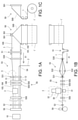
- FIG. 1A is a schematic plan view of an exemplary bag making machine
- FIG. 1B is a front view of FIG. 1A
- FIG. 1C is a side view of FIG. 1A
- 2A is an enlarged plan view of the area S of FIG. 1A
- FIG. 2B is a rear view of FIG. 2A
- FIG. 2C is a partial plan view of the expansion roller in the area T of FIG. 2A
- FIG. 3 is a diagram showing the bag of FIG. 1A in detail. It is sectional drawing of the folded laminated film.
- FIG. 5A shows an exemplary horn and anvil
- FIG. 5B shows an exemplary sequence of protrusions of FIG. 5A. 6A-6C show exemplary ultrasonic welding.
- FIG. 7A shows another exemplary horn and anvil
- FIG. 7B shows another exemplary sequence of protrusions of FIG. 7A
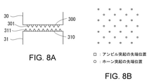
- FIG. 8A shows another exemplary horn and anvil
- FIG. 8B illustrates the positional relationship between the tip of the horn protrusion and the tip of the anvil protrusion.
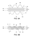
- 9A and 9B show another exemplary ultrasonic welding.
- 10A, 10B show another exemplary projection
- FIGS. 10C, 10D show another exemplary arrangement of protrusions.
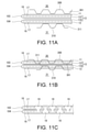
- 11A-11C show another exemplary ultrasonic welding.
- 12A is a plan view of an exemplary bag
- FIG. 12B is an enlarged view of the region P of FIG. 12A
- FIG. 12C is a sectional view taken along line QQ of FIG.
- FIG. 12B and FIG. 12D is a cross-sectional view of FIG. 12B. It is a cross-sectional view taken along the line RR.
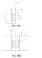
- FIG. 13A shows an exemplary ultrasonic welding region in the bag and
- FIG. 13B shows an exemplary ultrasonic welding region in the web.
- 14A, 14B show yet another exemplary ultrasonic welding region in the bag.
- FIGS. 1A-1C An exemplary bag making machine is shown in FIGS. 1A-1C.
- Bags 10 (FIG. 1A) are sequentially manufactured by a bag making machine.
- the web 1 is continuously fed from the original fabric 1'in its length direction (its continuous direction) at a constant speed, and is folded in half by the first folding device 50.
- the first folding device 50 includes a triangular plate 500 and a pair of grip rollers 501.
- the web 1 is folded in half along the longitudinal center line by the triangular plate 500 and the grip roller 501 during transportation.
- Reference numeral 100 in FIG. 1A indicates a folding edge resulting from the folding of the web 1.
- Reference numerals 101 and 102 in FIG. 1A indicate both sides of the web 1 aligned with each other by folding the web 1 in half.
- the folded web 1 is then appropriately switched from continuous transport to intermittent transport by a dancer device 51 including a dancer roller.
- a transport device 52 including a pair of transport rollers is provided in the downstream portion of the bag making machine, and the web 1 is intermittently transported in the length direction of the web 1.
- the transport direction of the web 1 is indicated by reference numeral X1.
- the web 1 is then further folded by a second folding device 53 to include two continuous body portions 11, 12 and a continuous gusset portion 13 folded between these body portions 11, 12. , Made from web 1.
- the second folding device 53 includes a pair of expansion rollers 532 (FIG. 1B) arranged downstream of the pair of guide rollers 530 and upstream of the pair of guide rollers 531.
- the web 1 is expanded by the expansion roller 532 in the section from the guide roller 530 to the guide roller 531 to provide a space between the two layers of the web 1.
- the second folding device 53 is further provided with a first forming plate 533 provided downstream of the expansion roller 532 and a second forming plate 533 provided following the downstream of the first forming plate 533.
- a forming plate 534 is provided.
- the first forming plate 533 has a trapezoidal shape.
- the first forming plate 533 is arranged in the space formed by the expansion roller 532 so as to abut from the inside of the web 1 on the portion including the bent edge 100 of the web 1.
- the first forming plate 533 is oriented so as to narrow toward the downstream.
- the second forming plate 534 has a triangular shape.
- the second forming plate 534 is arranged so as to abut from the outside on the portion including the bent edge 100.
- the second forming plate 534 narrows toward the downstream and toward the web 1, and one apex 5340 (FIG. 2B) becomes the downstream end of the second forming plate 534 and enters the web 1 and approaches the guide roller 531. , Contact the bent edge 100 of the web 1.
- the portion including the bent edge 100 is guided to the second forming plate 534 in a state of being expanded by the first forming plate 533, and then between the two layers of the web 1 by the second forming plate 534. It is folded back in the opposite direction along the bending edge 100 so as to enter. Then, in that state, the web 1 passes between the pair of guide rollers 531.
- the portion including the bent edge 100 is folded between the two layers of the web 1 resulting in a continuous gusset portion 13, and the two layers of the web 1 are two continuous trunk portions. It becomes 11 and 12.
- the bent edge 100 becomes the inner edge of the gusset portion 13.
- the gusset portion 13 is divided into two portions 131 and 132 (see FIG. 4) by its inner edge 100.
- Reference numerals 103 and 104 in FIG. 2A indicate the outer edge of the gusset portion 13, and this outer edge is also the boundary edge between the gusset portion 13 and the body portions 11 and 12.
- the web 1 is conveyed in such a folded state.
- FIG. 2C shows an enlarged view of the expansion roller 532 in the region T of FIG. 2A.
- each expansion roller 532 may have an R-shaped end 5320. Then, the end portion 5320 may be located on the folded side of the web 1 so as to be in contact with the inner surface of the web 1 to prevent the web 1 from being damaged.
- the continuous strip member 2 (FIG. 1A) is inserted between the two layers of the web 1 (hence, the torso 11 and 12) through the space secured by the expansion roller 532. good.
- the band-shaped member 2 of the embodiment may be a part that allows the bag 10 to be repeatedly opened and closed, and specifically, is a zipper made of a male material and a female material that are detachably fitted to each other.
- the zipper 2 is guided by the guide roller 54 with the male and female materials fitted to each other, turned around, and inserted between the body portions 11 and 12.
- the zipper 2 may be inserted between the body portions 11 and 12 and then irradiated with a laser by a laser device (not shown) and welded to the body portions 11 and 12. Therefore, the male material may be laser welded to the inner surface of the body portion 11/12, and the female material may be laser welded to the inner surface of the body portion 12/11.
- the laser device for welding may be disclosed in, for example, Japanese Patent Application Laid-Open No. 2017-47622. Instead of such a laser method, a heat sealing method may be adopted.
- the configuration of the bag 10 becomes complicated, the number of steps for incorporating or forming additional parts such as strip-shaped members, gussets, and spouts increases. As a result, the entire bag making process becomes complicated, but there is a concern that the bag making speed may decrease. For proper speed improvement, it is important to balance the specific process so that it does not become a bottleneck. For example, in the case of bag making including the welding process of the heat-sealing type zipper 2, if the welding of the heat-sealing type zipper 2 is the bottleneck, the laser method is used as the welding of the zipper 2 as in the present embodiment. Adopt to improve bag making speed.
- the heat sealing device 55 may include a plurality of sealing units 550. In the embodiment, three seal units 550 are provided, each including a pair of heated heat seal bars.
- the number of seal units 550 may be determined according to characteristics such as bag making speed.
- the plurality of seal units 550 may sequentially heat-seal the same portion to provide a high-quality heat seal at high speed, or may heat-seal different portions.
- the web 1 of the embodiment is a laminated film including a base material layer 16 made of a base material and a sealant layer 17 made of a sealant having a melting point lower than that of the base material.
- the base material may be, for example, nylon, PET, or the like.
- the sealant may be, for example, polyethylene, polypropylene or the like.
- the base material layer 16 forms the first surface of the web 1, and the sealant layer 17 forms the second surface of the web 1.
- the outer surface of the web 1 (hence the torso 11, 12 and the gusset 13) is formed by the substrate layer 16, and the inner surface of the web 1 (hence the torso 11, 12 and the gusset 13) is formed by the sealant layer 17.
- the web 1 is folded by the folding devices 50 and 53. Then, heat sealing is performed by utilizing the melting of the sealant of the sealant layer 17.
- the heat seal device 55 heat-seals the body portions 11 and 12 to each other in a region where they do not sandwich the gusset portion 13, and heat-seals the body portion 11 and the gusset portion 13 (part 131) to each other.
- the portion 12 and the gusset portion 13 (part 132) are heat-sealed with each other.
- the outer surfaces (opposing surfaces) of the portions 131 and 132 of the gusset portion 13 are formed of the base material layer 16, they are not heat-sealed by the heat-sealing device 55.
- the portions 131 and 132 are ultrasonically welded to each other by the ultrasonic welding device 3 each time the web 1 is intermittently conveyed.
- an ultrasonically welded region 15 (not shown in FIG. 1A, see FIG. 3) (hereinafter referred to as an ultrasonic welded region) is generated on the web 1 at a pitch corresponding to the width of the bag 10.
- the ultrasonic welding region 15 is internally included in the heat seal region 14.
- the ultrasonic welding device 3 is arranged downstream of the two seal units 550 and upstream of one seal unit 550.
- the web 1 is heat-sealed twice at the same location by two seal units 550 upstream of the ultrasonic welding device 3, thereby softening the body portions 11, 12 and the gusset portion 13.
- the ultrasonic welding device 3 performs ultrasonic welding on the body portions 11 and 12 and the gusset portion 13 in a softened and lightly attached state.
- the ultrasonic welding device 3 and the welding method using the ultrasonic welding device 3 will be described in detail later.
- the relative positional relationship of the ultrasonic welding device 3 with the heat sealing device 55 (sealing unit 550) is arbitrary, and may be appropriately determined according to the material of the web 1 (bag 10), the purpose of welding, and the like. Further, the order of ultrasonic welding and heat sealing may be appropriately determined according to the material of the web 1 (bag 10), the purpose of welding, and the like.
- the web 1 and zipper 2 are placed in the heat sealing region 14 in the width direction of the web 1 by a crosscut device 56 including a cutter, a cradle, etc. at each intermittent feed of the web 1. At the position, it is cross-cut across the ultrasonic welding region 15. As a result, the bags 10 are sequentially manufactured.
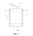
- FIG. 3 shows an enlarged view of the bag 10 of FIG. 1A.
- the bag 10 can be repeatedly opened and closed by the zipper 2.
- the body portions 11 and 12 and the gusset portion 13 are integrally formed by a single sheet separated from the web 1.
- the edges 101, 102 define the opening of the bag 10.
- the gusset portion 13 functions as a bottom gusset portion. Since the areas 14 and 15 are divided into two by the cross cut, they are located on both sides of the bag 10.
- the ultrasonic welding device 3 and the method of ultrasonically welding the portions 131 and 132 of the gusset portion 13 to each other using the ultrasonic welding device 3 will be described.
- the ultrasonic welding device 3 includes a horn 30 and an anvil 31 provided so as to face each other.
- the ultrasonic welding device 3 further includes a drive device 32 configured to move the horn 30 closer to and further from the anvil 31 and ultrasonically vibrate the horn 30.
- the horn 30 and the anvil 31 face each other up and down with the web 1 during intermittent transportation in between. Specifically, the horn 30 and the anvil 31 face each other with the body portions 11 and 12 and the gusset portion 13 folded between them in between.
- the body portions 11, 12 and the gusset portion 13 are sandwiched and pressurized by the horn 30 and the anvil 31.
- the horn 30 is vibrated at high frequencies by the drive device 32.
- the energy of ultrasonic vibration is transmitted to a portion to be welded (hereinafter referred to as a target location) and converted into frictional heat at the target location.
- the members are welded to each other at the target location due to the temperature rise due to the frictional heat.
- the gusset portion 13 is made of a single material such as polyethylene, the facing surfaces of the portions 131 and 132 are welded to each other.
- the gusset portion 13 is a laminated film in which the facing surfaces of the portions 131 and 132 are formed of a base material layer, the protrusions 311 of the anvil 31 and / or the protrusions 301 of the horn 30 (FIGS. 5A and 7A, which will be described later).
- the base material layer is broken by (see FIG. 8A and the like), and the sealant layer of the laminated film is melted, so that the facing surfaces of the portions 131 and 132 are substantially welded to each other.
- the ultrasonic welding conditions including frequency, amplitude, vibration time, pressing force, etc. are appropriately selected according to the material of the welded portions 131 and 132, the required welding strength, and the like.
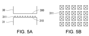
- the horn 30 includes a flat facing surface 300 facing the anvil 31.
- the anvil 31 includes a flat facing surface 310 facing the horn 30 and a plurality of protrusions 311 protruding from the facing surface 310.
- the protrusion 311 may be pointed. As shown in the plan view of FIG. 5B, the protrusions 311 may be arranged two-dimensionally.
- the protrusion 311 penetrates at least the outer substrate layer 16 of the web 1. Then, it penetrates into the inner sealant layer 17. More specifically, the protrusion 311 is pierced into the body portion 11, 12 and the portion 131, 132 until it penetrates the body portion 12 and the portions 131, 132 of the gusset portion 13 and reaches the opposite body portion 11. .. Then, in that state, the horn 30 is ultrasonically vibrated. By this ultrasonic vibration, the portions 131 and 132 are ultrasonically welded to each other as shown in FIG. 6C.
- the protrusion 311 Since the protrusion 311 has entered the laminated portion consisting of the body portions 11, 12 and the gusset portion 13, the distance between the horn 30 and the anvil 31 is shortened, and therefore the distance between the horn 30 / anvil 31 and the target portion is shortened. The distance is shortened. As a result, the vibration energy is efficiently transmitted to the target location, and the temperature of the target location rises in a short time. Therefore, the protrusion 311 improves the efficiency of ultrasonic welding.
- the heat seal by the seal unit 550 softens the web 1 (its base material layer 16) before the ultrasonic welding. This facilitates the entry of the protrusion 311 into the web 1, specifically the piercing.
- the sealant of the sealant layer 17 is melted by the ultrasonic vibration of the horn 30 and flows into each through hole of the base material layer 16. It is squeezed and filled, and as shown in FIG. 6C, a sealant filling portion 18 is formed.
- the filling portions 18 integrally weld the body portions 11, 12 and the portions 131, 132, thereby improving the welding strength of the ultrasonic welding region 15.
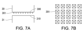
- a plurality of protrusions 301 may be two-dimensionally arranged so as to project from the facing surface 300 of the horn 30 instead of the facing surface 310 of the anvil 31. This also makes it possible to achieve the above effect.
- both the horn 30 and the anvil 31 may be provided with protrusions 301 and 311.
- the protrusions 301 of the horn 30 and the protrusions 311 of the anvil 31 are arranged so as to be offset from each other in a direction perpendicular to their facing directions so that their tips do not face each other.
- both the horn 30 and the anvil 31 have protrusions 301 and 311, more efficient ultrasonic welding can be performed.
- the protrusions 301/311 may have a square pyramid shape.
- the base of the square pyramid may be a rectangle (including a square) (FIG. 5B, FIG. 7B) or a rhombus (FIG. 10A).
- the protrusions 301/311 may have a polygonal pyramid shape other than the square pyramid, respectively.
- the protrusions 301/311 may be conical as shown in FIG. 10B.
- the protrusions 301/311 may be regularly arranged in the vertical and horizontal directions, for example, in a matrix, as shown in FIGS. 5B, 7B, 10C, and 10D. As shown in FIGS. 10C and 10D, for example, the protrusions 301/311 may be oriented so that the diagonal line of the bottom surface of the protrusions 301/311 is slanted with respect to the vertical and horizontal directions of the arrangement of the protrusions 301 / 311.
- the plurality of protrusions 301 may have different orientations from each other, and the plurality of protrusions 311 may have different orientations from each other.
- a protrusion 301/311 having a flat tip may be used.
- both the horn 30 and the anvil 31 are provided with protrusions 301, 311 having a flat tip.
- the protrusions 301, 311 are recessed into the laminated portion composed of the body portions 11, 12 and the gusset portion 13. Then, ultrasonic welding is performed by the ultrasonic vibration of the horn 30.
- FIG. 12A is a front view of the bag 10. After the shape of the bag 10 is completed by cross-cutting, a step of filling the contents may be carried out.
- the weight of the contents in the bag 10 exerts a force F (FIG. 12D) that tends to separate the gusset portions 13 (bottom gusset portions) portions 131 and 132 from each other in the ultrasonic welding region 15. As shown in FIG. 12B, this force F is larger in the outward component F1 of the bag 10 than in the vertical component F2 of the bag 10.
- the ultrasonic welding between the portions 131 and 132 opposes the force F that separates these portions 131 and 132.
- the strength of ultrasonic welding increases in proportion to the ratio of the welded portion in the cross section perpendicular to the direction of the component F1. Therefore, in the case of the semicircular ultrasonic welding region 15 as shown in FIG. 12B, the strength of ultrasonic welding is higher at the position of the line M than at the position of the line L.
- the ultrasonic welding region 15 is the bag as shown in FIG. 13A. It is preferable to have the length dimension L1 inside the bag, which is larger than the length dimension L2 on the outside (L1> L2). As shown in FIG. 13A, the ultrasonic welding region 15 of the bag 10 may have a trapezoidal shape that narrows toward the outside of the bag.
- the ultrasonic welding region 15 of FIG. 12B and the ultrasonic welding region 15 of FIG. 13A have the same area
- the ultrasonic welding region 15 of FIG. 13A has the same weight as that of FIG. 12B. Stronger against peeling by.
- the shapes of the facing surfaces 300 and 310 of the horn 30 and the anvil 31 are determined so that the ultrasonic welding region 15 of FIG. 13B is formed on the web 1 by the ultrasonic welding device 3 (FIG. 1A).
- the web 1 is cross-cut at the cross-cut position 560 by the cross-cut device 56 (FIG. 1A), and the ultrasonic welding region 15 is divided into two.
- the bag 10 having the trapezoidal ultrasonic welding region 15 is manufactured.
- the corner of the ultrasonic welding region 15 May have an R shape.
- the ultrasonic welding region 15 is not limited to the trapezoidal shape as shown in FIG. 14A, but may be a square shape having R-shaped corners as shown in FIG. 14B.
- the ultrasonic welding region 15 of FIGS. 14A and 14B may also be formed by the method described in FIG. 13B.
- the projection 301/311 improves the efficiency of ultrasonic welding.
- the welding method may be applied not to the web 1 but to the body portion 11, the body portion 12, and the gusset portion 13 integrally formed by folding a single-leaf sheet. Further, the welding method may be applied to the body portion 11, the body portion 12, and the gusset portion 13 as separate parts.
- the gusset portion 13 may function as a heaven gusset portion instead of the bottom gusset portion.
- the welding method may be applied to the side gusset portion folded into the body portions 11 and 12 as in Patent Document 1.
- a material having thermoplasticity may be widely used in addition to the laminated film including the base material layer 16 and the sealant layer 17 as in the embodiment.
- a monomaterial material that is superior to recycling may be used.
- a material that can reduce the amount of resin discarded such as a material composed of paper as a base material and a resin coated on the paper, may be used.
- a biodegradable material may be used.
Landscapes
- Engineering & Computer Science (AREA)
- Mechanical Engineering (AREA)
- Chemical & Material Sciences (AREA)
- Composite Materials (AREA)
- Making Paper Articles (AREA)
Priority Applications (4)
| Application Number | Priority Date | Filing Date | Title |
|---|---|---|---|
| EP21844616.9A EP4183565B1 (en) | 2020-07-20 | 2021-05-19 | Bag making method and welding method |
| CN202180046473.3A CN115803179A (zh) | 2020-07-20 | 2021-05-19 | 制袋方法、及熔接方法 |
| US18/013,540 US12011898B2 (en) | 2020-07-20 | 2021-05-19 | Bag making method |
| JP2021577590A JP7286200B2 (ja) | 2020-07-20 | 2021-05-19 | 製袋方法、および、溶着方法 |
Applications Claiming Priority (2)
| Application Number | Priority Date | Filing Date | Title |
|---|---|---|---|
| JP2020-123841 | 2020-07-20 | ||
| JP2020123841 | 2020-07-20 |
Publications (1)
| Publication Number | Publication Date |
|---|---|
| WO2022018948A1 true WO2022018948A1 (ja) | 2022-01-27 |
Family
ID=79728645
Family Applications (1)
| Application Number | Title | Priority Date | Filing Date |
|---|---|---|---|
| PCT/JP2021/019009 Ceased WO2022018948A1 (ja) | 2020-07-20 | 2021-05-19 | 製袋方法、および、溶着方法 |
Country Status (5)
| Country | Link |
|---|---|
| US (1) | US12011898B2 (enExample) |
| EP (1) | EP4183565B1 (enExample) |
| JP (1) | JP7286200B2 (enExample) |
| CN (1) | CN115803179A (enExample) |
| WO (1) | WO2022018948A1 (enExample) |
Families Citing this family (1)
| Publication number | Priority date | Publication date | Assignee | Title |
|---|---|---|---|---|
| US11999128B2 (en) * | 2022-02-09 | 2024-06-04 | Paper Converting Machine Company | Method of aligning air burst on bag wicketer processing line |
Citations (4)
| Publication number | Priority date | Publication date | Assignee | Title |
|---|---|---|---|---|
| JPS61502666A (ja) * | 1984-07-12 | 1986-11-20 | ザ・コカ−コ−ラ・カンパニ− | 超音波スポット溶接組立体及び方法 |
| JP2017217764A (ja) * | 2016-06-03 | 2017-12-14 | 株式会社細川洋行 | 包装袋のシール方法及び包装袋 |
| JP2018140519A (ja) * | 2017-02-27 | 2018-09-13 | 株式会社フジシールインターナショナル | パウチ容器のヒートシール装置 |
| JP2019533591A (ja) * | 2016-10-18 | 2019-11-21 | レシラックス エヌブイResilux Nv | プラスチックの超音波溶接用ソノトロードおよびアンビル、並びにプラスチック容器の製造方法 |
Family Cites Families (19)
| Publication number | Priority date | Publication date | Assignee | Title |
|---|---|---|---|---|
| CN85106066A (zh) * | 1985-03-21 | 1986-09-17 | 可口可乐公司 | 超音波点焊组件及方法 |
| JP2971185B2 (ja) * | 1991-06-28 | 1999-11-02 | 住友ベークライト株式会社 | 容器本体のフランジ部への微小凹部の形成方法 |
| JP3934747B2 (ja) * | 1997-08-08 | 2007-06-20 | 株式会社ファブリカトヤマ | シール装置の制御方法 |
| FR2784051B1 (fr) * | 1998-10-06 | 2000-12-22 | Unisabi Sa | Dispositif de soudage par ultrasons |
| JP2000202910A (ja) * | 1999-01-11 | 2000-07-25 | Nippon Plast Co Ltd | トリム体の成形方法及びそのトリム体 |
| DE60038639T2 (de) * | 1999-12-02 | 2009-05-14 | Totani Corp. | Kunststofftasche |
| DE10123309A1 (de) * | 2001-05-14 | 2002-12-05 | Imtex S L | Verfahren zum Verbinden von Stücken aus textilem Gewebe |
| JP4451244B2 (ja) * | 2004-08-02 | 2010-04-14 | 大日本住友製薬株式会社 | 包装袋のシール方法、包装袋、包装袋のシール装置、および製袋装置 |
| ES2369607T3 (es) * | 2005-07-20 | 2011-12-02 | Indag Gesellschaft für Industriebedarf mbH & Co. Betriebs KG | Dispositivo y procedimiento para aplicar una costura de soldadura, así como bolsa de lámina. |
| AU2008364073B2 (en) * | 2008-11-13 | 2011-08-25 | Totani Corporation | Plastic bag making apparatus |
| JP5985930B2 (ja) * | 2012-08-29 | 2016-09-06 | 昭和電工パッケージング株式会社 | 密封容器 |
| JP5323249B1 (ja) * | 2012-12-28 | 2013-10-23 | トタニ技研工業株式会社 | 製袋機 |
| JP2015013390A (ja) * | 2013-07-03 | 2015-01-22 | 大日本印刷株式会社 | 製袋機および製袋方法 |
| JP6537979B2 (ja) | 2014-01-24 | 2019-07-03 | 株式会社細川洋行 | ガゼット袋、ガゼット袋の製造方法、及び積層体の接合方法 |
| CN105666938B (zh) * | 2014-11-18 | 2018-12-28 | 户谷技研工业株式会社 | 塑料袋制作设备 |
| KR20170043971A (ko) * | 2015-10-14 | 2017-04-24 | (주)인터팩 | 초음파용 라미네이트 튜브 접합장치 |
| KR20170108189A (ko) * | 2016-03-16 | 2017-09-27 | (주)엘지하우시스 | 이종소재 바닥재의 초음파 용착장치 및 초음파 용착방법 |
| JP6688666B2 (ja) * | 2016-04-15 | 2020-04-28 | 株式会社細川洋行 | ガゼット袋、及びガゼット袋の製造方法 |
| WO2019097942A1 (ja) * | 2017-11-14 | 2019-05-23 | トタニ技研工業株式会社 | 溶着方法および溶着装置 |
-
2021
- 2021-05-19 EP EP21844616.9A patent/EP4183565B1/en active Active
- 2021-05-19 CN CN202180046473.3A patent/CN115803179A/zh active Pending
- 2021-05-19 US US18/013,540 patent/US12011898B2/en active Active
- 2021-05-19 JP JP2021577590A patent/JP7286200B2/ja active Active
- 2021-05-19 WO PCT/JP2021/019009 patent/WO2022018948A1/ja not_active Ceased
Patent Citations (4)
| Publication number | Priority date | Publication date | Assignee | Title |
|---|---|---|---|---|
| JPS61502666A (ja) * | 1984-07-12 | 1986-11-20 | ザ・コカ−コ−ラ・カンパニ− | 超音波スポット溶接組立体及び方法 |
| JP2017217764A (ja) * | 2016-06-03 | 2017-12-14 | 株式会社細川洋行 | 包装袋のシール方法及び包装袋 |
| JP2019533591A (ja) * | 2016-10-18 | 2019-11-21 | レシラックス エヌブイResilux Nv | プラスチックの超音波溶接用ソノトロードおよびアンビル、並びにプラスチック容器の製造方法 |
| JP2018140519A (ja) * | 2017-02-27 | 2018-09-13 | 株式会社フジシールインターナショナル | パウチ容器のヒートシール装置 |
Non-Patent Citations (1)
| Title |
|---|
| See also references of EP4183565A4 |
Also Published As
| Publication number | Publication date |
|---|---|
| EP4183565A4 (en) | 2024-10-30 |
| US12011898B2 (en) | 2024-06-18 |
| CN115803179A (zh) | 2023-03-14 |
| EP4183565B1 (en) | 2025-10-15 |
| US20230256698A1 (en) | 2023-08-17 |
| EP4183565A1 (en) | 2023-05-24 |
| JP7286200B2 (ja) | 2023-06-05 |
| JPWO2022018948A1 (enExample) | 2022-01-27 |
Similar Documents
| Publication | Publication Date | Title |
|---|---|---|
| JP4615049B2 (ja) | 横シーリングのためのデバイス及び方法 | |
| JP6544935B2 (ja) | 電子レンジ用包装袋及び製袋方法 | |
| JP7119239B2 (ja) | 紙袋を製造するためのピロー包装機 | |
| TWI532554B (zh) | 袋子和閉合袋體之方法 | |
| JP7286200B2 (ja) | 製袋方法、および、溶着方法 | |
| JP2014034166A (ja) | プラスチックフィルム接合方法 | |
| JP4057157B2 (ja) | プラスチック袋の製造方法 | |
| JP4141128B2 (ja) | ジッパー付袋の製造方法及びそれに用いるジッパー開口部サイドシール装置 | |
| JPH0571444B2 (enExample) | ||
| JPWO2022018948A5 (enExample) | ||
| JP5635542B2 (ja) | 製袋充填機における袋開封部形成装置 | |
| JP2022022862A (ja) | ガゼット袋の製造方法及びガゼット袋 | |
| JP7359494B2 (ja) | 製袋機、製袋方法、および、袋 | |
| CN104647803B (zh) | 塑料膜的接合方法 | |
| JP7168184B2 (ja) | 製袋機、製袋方法、および、袋 | |
| JP7594302B2 (ja) | 製袋充填機における超音波横シール装置 | |
| CN118849524A (zh) | 包装袋的制造系统 | |
| JP2004359296A (ja) | 印刷袋体及びその製袋方法 | |
| JPS6337693B2 (enExample) | ||
| WO2022180986A1 (ja) | 製袋方法、および、製袋機 | |
| JP2021187486A (ja) | 包装袋 | |
| KR101524187B1 (ko) | 제1 부재 및 제2 부재를 동시에 융착하는 수용 백 제조 장치 | |
| JP2002002718A (ja) | 袋、および袋の製造方法 | |
| JP2004338770A (ja) | ジッパー付袋、その製造方法及び装置 | |
| JP2001158056A (ja) | 製袋機 |
Legal Events
| Date | Code | Title | Description |
|---|---|---|---|
| ENP | Entry into the national phase |
Ref document number: 2021577590 Country of ref document: JP Kind code of ref document: A |
|
| 121 | Ep: the epo has been informed by wipo that ep was designated in this application |
Ref document number: 21844616 Country of ref document: EP Kind code of ref document: A1 |
|
| NENP | Non-entry into the national phase |
Ref country code: DE |
|
| ENP | Entry into the national phase |
Ref document number: 2021844616 Country of ref document: EP Effective date: 20230220 |
|
| WWG | Wipo information: grant in national office |
Ref document number: 2021844616 Country of ref document: EP |