WO2022018948A1 - Bag making method and welding method - Google Patents
Bag making method and welding method Download PDFInfo
- Publication number
- WO2022018948A1 WO2022018948A1 PCT/JP2021/019009 JP2021019009W WO2022018948A1 WO 2022018948 A1 WO2022018948 A1 WO 2022018948A1 JP 2021019009 W JP2021019009 W JP 2021019009W WO 2022018948 A1 WO2022018948 A1 WO 2022018948A1
- Authority
- WO
- WIPO (PCT)
- Prior art keywords
- horn
- anvil
- gusset
- torso
- bag
- Prior art date
Links
Images


Classifications
-
- B—PERFORMING OPERATIONS; TRANSPORTING
- B31—MAKING ARTICLES OF PAPER, CARDBOARD OR MATERIAL WORKED IN A MANNER ANALOGOUS TO PAPER; WORKING PAPER, CARDBOARD OR MATERIAL WORKED IN A MANNER ANALOGOUS TO PAPER
- B31B—MAKING CONTAINERS OF PAPER, CARDBOARD OR MATERIAL WORKED IN A MANNER ANALOGOUS TO PAPER
- B31B70/00—Making flexible containers, e.g. envelopes or bags
- B31B70/60—Uniting opposed surfaces or edges; Taping
- B31B70/64—Uniting opposed surfaces or edges; Taping by applying heat or pressure
- B31B70/644—Making seals parallel to the direction of movement, i.e. longitudinal sealing
-
- B—PERFORMING OPERATIONS; TRANSPORTING
- B31—MAKING ARTICLES OF PAPER, CARDBOARD OR MATERIAL WORKED IN A MANNER ANALOGOUS TO PAPER; WORKING PAPER, CARDBOARD OR MATERIAL WORKED IN A MANNER ANALOGOUS TO PAPER
- B31B—MAKING CONTAINERS OF PAPER, CARDBOARD OR MATERIAL WORKED IN A MANNER ANALOGOUS TO PAPER
- B31B70/00—Making flexible containers, e.g. envelopes or bags
- B31B70/60—Uniting opposed surfaces or edges; Taping
- B31B70/64—Uniting opposed surfaces or edges; Taping by applying heat or pressure
- B31B70/645—Making seals transversally to the direction of movement
-
- B—PERFORMING OPERATIONS; TRANSPORTING
- B29—WORKING OF PLASTICS; WORKING OF SUBSTANCES IN A PLASTIC STATE IN GENERAL
- B29C—SHAPING OR JOINING OF PLASTICS; SHAPING OF MATERIAL IN A PLASTIC STATE, NOT OTHERWISE PROVIDED FOR; AFTER-TREATMENT OF THE SHAPED PRODUCTS, e.g. REPAIRING
- B29C65/00—Joining or sealing of preformed parts, e.g. welding of plastics materials; Apparatus therefor
- B29C65/02—Joining or sealing of preformed parts, e.g. welding of plastics materials; Apparatus therefor by heating, with or without pressure
- B29C65/08—Joining or sealing of preformed parts, e.g. welding of plastics materials; Apparatus therefor by heating, with or without pressure using ultrasonic vibrations
-
- B—PERFORMING OPERATIONS; TRANSPORTING
- B29—WORKING OF PLASTICS; WORKING OF SUBSTANCES IN A PLASTIC STATE IN GENERAL
- B29C—SHAPING OR JOINING OF PLASTICS; SHAPING OF MATERIAL IN A PLASTIC STATE, NOT OTHERWISE PROVIDED FOR; AFTER-TREATMENT OF THE SHAPED PRODUCTS, e.g. REPAIRING
- B29C65/00—Joining or sealing of preformed parts, e.g. welding of plastics materials; Apparatus therefor
- B29C65/74—Joining or sealing of preformed parts, e.g. welding of plastics materials; Apparatus therefor by welding and severing, or by joining and severing, the severing being performed in the area to be joined, next to the area to be joined, in the joint area or next to the joint area
-
- B—PERFORMING OPERATIONS; TRANSPORTING
- B29—WORKING OF PLASTICS; WORKING OF SUBSTANCES IN A PLASTIC STATE IN GENERAL
- B29C—SHAPING OR JOINING OF PLASTICS; SHAPING OF MATERIAL IN A PLASTIC STATE, NOT OTHERWISE PROVIDED FOR; AFTER-TREATMENT OF THE SHAPED PRODUCTS, e.g. REPAIRING
- B29C65/00—Joining or sealing of preformed parts, e.g. welding of plastics materials; Apparatus therefor
- B29C65/78—Means for handling the parts to be joined, e.g. for making containers or hollow articles, e.g. means for handling sheets, plates, web-like materials, tubular articles, hollow articles or elements to be joined therewith; Means for discharging the joined articles from the joining apparatus
- B29C65/7858—Means for handling the parts to be joined, e.g. for making containers or hollow articles, e.g. means for handling sheets, plates, web-like materials, tubular articles, hollow articles or elements to be joined therewith; Means for discharging the joined articles from the joining apparatus characterised by the feeding movement of the parts to be joined
- B29C65/7888—Means for handling of moving sheets or webs
- B29C65/7891—Means for handling of moving sheets or webs of discontinuously moving sheets or webs
-
- B—PERFORMING OPERATIONS; TRANSPORTING
- B29—WORKING OF PLASTICS; WORKING OF SUBSTANCES IN A PLASTIC STATE IN GENERAL
- B29C—SHAPING OR JOINING OF PLASTICS; SHAPING OF MATERIAL IN A PLASTIC STATE, NOT OTHERWISE PROVIDED FOR; AFTER-TREATMENT OF THE SHAPED PRODUCTS, e.g. REPAIRING
- B29C66/00—General aspects of processes or apparatus for joining preformed parts
- B29C66/01—General aspects dealing with the joint area or with the area to be joined
- B29C66/03—After-treatments in the joint area
- B29C66/032—Mechanical after-treatments
- B29C66/0326—Cutting, e.g. by using waterjets, or perforating
-
- B—PERFORMING OPERATIONS; TRANSPORTING
- B29—WORKING OF PLASTICS; WORKING OF SUBSTANCES IN A PLASTIC STATE IN GENERAL
- B29C—SHAPING OR JOINING OF PLASTICS; SHAPING OF MATERIAL IN A PLASTIC STATE, NOT OTHERWISE PROVIDED FOR; AFTER-TREATMENT OF THE SHAPED PRODUCTS, e.g. REPAIRING
- B29C66/00—General aspects of processes or apparatus for joining preformed parts
- B29C66/01—General aspects dealing with the joint area or with the area to be joined
- B29C66/05—Particular design of joint configurations
- B29C66/10—Particular design of joint configurations particular design of the joint cross-sections
- B29C66/11—Joint cross-sections comprising a single joint-segment, i.e. one of the parts to be joined comprising a single joint-segment in the joint cross-section
- B29C66/112—Single lapped joints
- B29C66/1122—Single lap to lap joints, i.e. overlap joints
-
- B—PERFORMING OPERATIONS; TRANSPORTING
- B29—WORKING OF PLASTICS; WORKING OF SUBSTANCES IN A PLASTIC STATE IN GENERAL
- B29C—SHAPING OR JOINING OF PLASTICS; SHAPING OF MATERIAL IN A PLASTIC STATE, NOT OTHERWISE PROVIDED FOR; AFTER-TREATMENT OF THE SHAPED PRODUCTS, e.g. REPAIRING
- B29C66/00—General aspects of processes or apparatus for joining preformed parts
- B29C66/40—General aspects of joining substantially flat articles, e.g. plates, sheets or web-like materials; Making flat seams in tubular or hollow articles; Joining single elements to substantially flat surfaces
- B29C66/41—Joining substantially flat articles ; Making flat seams in tubular or hollow articles
- B29C66/43—Joining a relatively small portion of the surface of said articles
- B29C66/431—Joining the articles to themselves
-
- B—PERFORMING OPERATIONS; TRANSPORTING
- B29—WORKING OF PLASTICS; WORKING OF SUBSTANCES IN A PLASTIC STATE IN GENERAL
- B29C—SHAPING OR JOINING OF PLASTICS; SHAPING OF MATERIAL IN A PLASTIC STATE, NOT OTHERWISE PROVIDED FOR; AFTER-TREATMENT OF THE SHAPED PRODUCTS, e.g. REPAIRING
- B29C66/00—General aspects of processes or apparatus for joining preformed parts
- B29C66/70—General aspects of processes or apparatus for joining preformed parts characterised by the composition, physical properties or the structure of the material of the parts to be joined; Joining with non-plastics material
- B29C66/72—General aspects of processes or apparatus for joining preformed parts characterised by the composition, physical properties or the structure of the material of the parts to be joined; Joining with non-plastics material characterised by the structure of the material of the parts to be joined
- B29C66/723—General aspects of processes or apparatus for joining preformed parts characterised by the composition, physical properties or the structure of the material of the parts to be joined; Joining with non-plastics material characterised by the structure of the material of the parts to be joined being multi-layered
- B29C66/7232—General aspects of processes or apparatus for joining preformed parts characterised by the composition, physical properties or the structure of the material of the parts to be joined; Joining with non-plastics material characterised by the structure of the material of the parts to be joined being multi-layered comprising a non-plastics layer
- B29C66/72327—General aspects of processes or apparatus for joining preformed parts characterised by the composition, physical properties or the structure of the material of the parts to be joined; Joining with non-plastics material characterised by the structure of the material of the parts to be joined being multi-layered comprising a non-plastics layer consisting of natural products or their composites, not provided for in B29C66/72321 - B29C66/72324
- B29C66/72328—Paper
-
- B—PERFORMING OPERATIONS; TRANSPORTING
- B29—WORKING OF PLASTICS; WORKING OF SUBSTANCES IN A PLASTIC STATE IN GENERAL
- B29C—SHAPING OR JOINING OF PLASTICS; SHAPING OF MATERIAL IN A PLASTIC STATE, NOT OTHERWISE PROVIDED FOR; AFTER-TREATMENT OF THE SHAPED PRODUCTS, e.g. REPAIRING
- B29C66/00—General aspects of processes or apparatus for joining preformed parts
- B29C66/70—General aspects of processes or apparatus for joining preformed parts characterised by the composition, physical properties or the structure of the material of the parts to be joined; Joining with non-plastics material
- B29C66/73—General aspects of processes or apparatus for joining preformed parts characterised by the composition, physical properties or the structure of the material of the parts to be joined; Joining with non-plastics material characterised by the intensive physical properties of the material of the parts to be joined, by the optical properties of the material of the parts to be joined, by the extensive physical properties of the parts to be joined, by the state of the material of the parts to be joined or by the material of the parts to be joined being a thermoplastic or a thermoset
- B29C66/739—General aspects of processes or apparatus for joining preformed parts characterised by the composition, physical properties or the structure of the material of the parts to be joined; Joining with non-plastics material characterised by the intensive physical properties of the material of the parts to be joined, by the optical properties of the material of the parts to be joined, by the extensive physical properties of the parts to be joined, by the state of the material of the parts to be joined or by the material of the parts to be joined being a thermoplastic or a thermoset characterised by the material of the parts to be joined being a thermoplastic or a thermoset
- B29C66/7392—General aspects of processes or apparatus for joining preformed parts characterised by the composition, physical properties or the structure of the material of the parts to be joined; Joining with non-plastics material characterised by the intensive physical properties of the material of the parts to be joined, by the optical properties of the material of the parts to be joined, by the extensive physical properties of the parts to be joined, by the state of the material of the parts to be joined or by the material of the parts to be joined being a thermoplastic or a thermoset characterised by the material of the parts to be joined being a thermoplastic or a thermoset characterised by the material of at least one of the parts being a thermoplastic
- B29C66/73921—General aspects of processes or apparatus for joining preformed parts characterised by the composition, physical properties or the structure of the material of the parts to be joined; Joining with non-plastics material characterised by the intensive physical properties of the material of the parts to be joined, by the optical properties of the material of the parts to be joined, by the extensive physical properties of the parts to be joined, by the state of the material of the parts to be joined or by the material of the parts to be joined being a thermoplastic or a thermoset characterised by the material of the parts to be joined being a thermoplastic or a thermoset characterised by the material of at least one of the parts being a thermoplastic characterised by the materials of both parts being thermoplastics
-
- B—PERFORMING OPERATIONS; TRANSPORTING
- B29—WORKING OF PLASTICS; WORKING OF SUBSTANCES IN A PLASTIC STATE IN GENERAL
- B29C—SHAPING OR JOINING OF PLASTICS; SHAPING OF MATERIAL IN A PLASTIC STATE, NOT OTHERWISE PROVIDED FOR; AFTER-TREATMENT OF THE SHAPED PRODUCTS, e.g. REPAIRING
- B29C66/00—General aspects of processes or apparatus for joining preformed parts
- B29C66/80—General aspects of machine operations or constructions and parts thereof
- B29C66/83—General aspects of machine operations or constructions and parts thereof characterised by the movement of the joining or pressing tools
- B29C66/832—Reciprocating joining or pressing tools
- B29C66/8322—Joining or pressing tools reciprocating along one axis
-
- B—PERFORMING OPERATIONS; TRANSPORTING
- B29—WORKING OF PLASTICS; WORKING OF SUBSTANCES IN A PLASTIC STATE IN GENERAL
- B29C—SHAPING OR JOINING OF PLASTICS; SHAPING OF MATERIAL IN A PLASTIC STATE, NOT OTHERWISE PROVIDED FOR; AFTER-TREATMENT OF THE SHAPED PRODUCTS, e.g. REPAIRING
- B29C66/00—General aspects of processes or apparatus for joining preformed parts
- B29C66/80—General aspects of machine operations or constructions and parts thereof
- B29C66/84—Specific machine types or machines suitable for specific applications
- B29C66/851—Bag or container making machines
- B29C66/8511—Bag making machines
-
- B—PERFORMING OPERATIONS; TRANSPORTING
- B31—MAKING ARTICLES OF PAPER, CARDBOARD OR MATERIAL WORKED IN A MANNER ANALOGOUS TO PAPER; WORKING PAPER, CARDBOARD OR MATERIAL WORKED IN A MANNER ANALOGOUS TO PAPER
- B31B—MAKING CONTAINERS OF PAPER, CARDBOARD OR MATERIAL WORKED IN A MANNER ANALOGOUS TO PAPER
- B31B70/00—Making flexible containers, e.g. envelopes or bags
- B31B70/14—Cutting, e.g. perforating, punching, slitting or trimming
- B31B70/16—Cutting webs
-
- B—PERFORMING OPERATIONS; TRANSPORTING
- B31—MAKING ARTICLES OF PAPER, CARDBOARD OR MATERIAL WORKED IN A MANNER ANALOGOUS TO PAPER; WORKING PAPER, CARDBOARD OR MATERIAL WORKED IN A MANNER ANALOGOUS TO PAPER
- B31B—MAKING CONTAINERS OF PAPER, CARDBOARD OR MATERIAL WORKED IN A MANNER ANALOGOUS TO PAPER
- B31B70/00—Making flexible containers, e.g. envelopes or bags
- B31B70/26—Folding sheets, blanks or webs
- B31B70/262—Folding sheets, blanks or webs involving longitudinally folding, i.e. along a line parallel to the direction of movement
- B31B70/266—Folding sheets, blanks or webs involving longitudinally folding, i.e. along a line parallel to the direction of movement involving gusset-forming
-
- B—PERFORMING OPERATIONS; TRANSPORTING
- B31—MAKING ARTICLES OF PAPER, CARDBOARD OR MATERIAL WORKED IN A MANNER ANALOGOUS TO PAPER; WORKING PAPER, CARDBOARD OR MATERIAL WORKED IN A MANNER ANALOGOUS TO PAPER
- B31B—MAKING CONTAINERS OF PAPER, CARDBOARD OR MATERIAL WORKED IN A MANNER ANALOGOUS TO PAPER
- B31B70/00—Making flexible containers, e.g. envelopes or bags
- B31B70/60—Uniting opposed surfaces or edges; Taping
- B31B70/64—Uniting opposed surfaces or edges; Taping by applying heat or pressure
- B31B70/66—Uniting opposed surfaces or edges; Taping by applying heat or pressure by high-frequency electric heating
-
- B—PERFORMING OPERATIONS; TRANSPORTING
- B65—CONVEYING; PACKING; STORING; HANDLING THIN OR FILAMENTARY MATERIAL
- B65D—CONTAINERS FOR STORAGE OR TRANSPORT OF ARTICLES OR MATERIALS, e.g. BAGS, BARRELS, BOTTLES, BOXES, CANS, CARTONS, CRATES, DRUMS, JARS, TANKS, HOPPERS, FORWARDING CONTAINERS; ACCESSORIES, CLOSURES, OR FITTINGS THEREFOR; PACKAGING ELEMENTS; PACKAGES
- B65D33/00—Details of, or accessories for, sacks or bags
- B65D33/16—End- or aperture-closing arrangements or devices
- B65D33/25—Riveting; Dovetailing; Screwing; using press buttons or slide fasteners
-
- B—PERFORMING OPERATIONS; TRANSPORTING
- B29—WORKING OF PLASTICS; WORKING OF SUBSTANCES IN A PLASTIC STATE IN GENERAL
- B29L—INDEXING SCHEME ASSOCIATED WITH SUBCLASS B29C, RELATING TO PARTICULAR ARTICLES
- B29L2031/00—Other particular articles
- B29L2031/712—Containers; Packaging elements or accessories, Packages
- B29L2031/7128—Bags, sacks, sachets
-
- B—PERFORMING OPERATIONS; TRANSPORTING
- B31—MAKING ARTICLES OF PAPER, CARDBOARD OR MATERIAL WORKED IN A MANNER ANALOGOUS TO PAPER; WORKING PAPER, CARDBOARD OR MATERIAL WORKED IN A MANNER ANALOGOUS TO PAPER
- B31B—MAKING CONTAINERS OF PAPER, CARDBOARD OR MATERIAL WORKED IN A MANNER ANALOGOUS TO PAPER
- B31B2155/00—Flexible containers made from webs
- B31B2155/001—Flexible containers made from webs by folding webs longitudinally
- B31B2155/0014—Flexible containers made from webs by folding webs longitudinally having their openings facing transversally to the direction of movement
-
- B—PERFORMING OPERATIONS; TRANSPORTING
- B31—MAKING ARTICLES OF PAPER, CARDBOARD OR MATERIAL WORKED IN A MANNER ANALOGOUS TO PAPER; WORKING PAPER, CARDBOARD OR MATERIAL WORKED IN A MANNER ANALOGOUS TO PAPER
- B31B—MAKING CONTAINERS OF PAPER, CARDBOARD OR MATERIAL WORKED IN A MANNER ANALOGOUS TO PAPER
- B31B2160/00—Shape of flexible containers
- B31B2160/20—Shape of flexible containers with structural provision for thickness of contents
-
- B—PERFORMING OPERATIONS; TRANSPORTING
- B65—CONVEYING; PACKING; STORING; HANDLING THIN OR FILAMENTARY MATERIAL
- B65D—CONTAINERS FOR STORAGE OR TRANSPORT OF ARTICLES OR MATERIALS, e.g. BAGS, BARRELS, BOTTLES, BOXES, CANS, CARTONS, CRATES, DRUMS, JARS, TANKS, HOPPERS, FORWARDING CONTAINERS; ACCESSORIES, CLOSURES, OR FITTINGS THEREFOR; PACKAGING ELEMENTS; PACKAGES
- B65D2207/00—Standing packages
Definitions
- the present application relates to a bag making method and a welding method including welding two parts of a gusset part folded between two body parts to each other.
- a plastic bag a bag such as a pouch, for example, has two torso facing each other.
- the bag comprises a gusset that is folded between the torso to increase its capacity or to gain the independence of the bag.
- the gusset part is, for example, a side gusset part, a bottom gusset part, or a heaven gusset part.
- the gusset portion is divided into two parts by its bent edge.
- the two parts may be welded together at the edge of the bag to prevent the bag from expanding excessively or to enhance the bag's independence.
- the reason for enhancing the independence of the bag is that when the bag is placed on the mounting surface, the contact portion between the bag and the mounting surface is composed of both ends of the gusset portion (bottom gusset portion), and the contents are This is because, if filled, the edges of both ends are not in a straight line and come into contact with the mounting surface as the outer peripheral edge of a region having a predetermined area.
- Patent Document 1 discloses a method of ultrasonically welding two portions of a gusset portion to each other.
- the horn is brought into contact with one body portion and the anvil is brought into contact with the other body portion, and the two body portions and the gusset portion folded between these body portions are formed with the horn and the anvil. Hold and pressurize. Then, the two parts of the gusset portion are welded to each other by the ultrasonic vibration of the horn.
- the body portion located between the horn anvil and the gusset portion becomes a factor that lowers the transmission efficiency of vibration energy from the horn to the portion to be welded. Therefore, the two portions of the gusset portion may not be firmly welded to each other.
- An object of the present application is to provide a bag making method and a welding method for efficiently welding two parts of a gusset portion.
- a bag making method is provided.
- the bag making method is: The web is folded to form a continuous first torso, a continuous second torso, and a continuous gusset from the web, wherein the gussets are the first and second. Folded between the torso;
- the horn comprises sandwiching and pressurizing the first torso, the second torso, and the gusset folded between the first and second torso with a horn and anvil.
- the anvil has a facing surface facing the anvil, the anvil has an opposing surface facing the horn, and at least one of the horn and the anvil has a plurality of protrusions protruding from the facing surface;
- the first and first parts of the gusset are due to ultrasonic vibrations of the horn while the first body, the second body, and the gusset are sandwiched and pressurized by the horn and the anvil.
- a bag is manufactured by cross-cutting the web in the width direction of the web, with the first portion and the second portion crossing an ultrasonic welding region in which the horn and the anvil are ultrasonically welded to each other. , Equipped with.
- the bag making method may include manufacturing the bag having the ultrasonic welding region having a length dimension in the bag inclusion larger than the length dimension outside the bag.
- the bag making method may include manufacturing the bag having the trapezoidal ultrasonic welding region that narrows toward the outside of the bag.
- the bag making method may include manufacturing the bag having the gusset portion as a bottom gusset portion.
- the bag making method may include manufacturing the bag having the marks of the plurality of protrusions generated during ultrasonic welding using the horn and the anvil.
- a welding method in which the first portion and the second portion of the gusset portion folded between the first body portion and the second body portion are ultrasonically welded to each other.
- the welding method is:
- the horn comprises sandwiching and pressurizing the first torso, the second torso, and the gusset folded between the first and second torso with a horn and anvil.
- the anvil has a facing surface facing the anvil, the anvil has an opposing surface facing the horn, and at least one of the anvil or the horn has a plurality of protrusions protruding from the facing surface;
- the first and second parts due to ultrasonic vibrations of the horn while the first body, the second body, and the gusset are sandwiched and pressurized by the horn and the anvil. To be welded to each other.
- the plurality of protrusions may be pointed.
- the welding method is When the first body portion, the second body portion, and the gusset portion are sandwiched and pressed by the horn and the anvil, the plurality of protrusions penetrate the first or second body portion. As such, it may be provided to pierce the first or second body portion and the gusset portion.
- the welding method is When the first body portion, the second body portion, and the gusset portion are sandwiched and pressed by the horn and the anvil, the plurality of protrusions are formed on the first body portion, the first portion, and the like. And, it may be provided to pierce the first body portion, the second body portion, the first portion, and the second portion so as to penetrate the second portion.
- the plurality of protrusions may have a flat tip.
- the welding method is When the first body portion, the second body portion, and the gusset portion are sandwiched and pressed by the horn and the anvil, the plurality of protrusions are formed on the first body portion and the second body portion. , The first portion and the laminated portion including the second portion may be provided to be recessed.
- the first body portion, the second body portion, and the gusset portion may be a laminated film including a base material layer made of a base material and a sealant layer made of a sealant having a melting point lower than that of the base material, respectively. ..
- the welding method is The sealant is melted by the ultrasonic vibration of the horn, and the first body portion, the second body portion, the first part, and the second part are integrally welded using the sealant. May be equipped with.
- the welding method is The web may be folded to form the first torso, the second torso, and the gusset from the web.
- the first body portion, the second body portion, and the gusset portion are continuous and may be integrally formed.
- the first body portion, the second body portion, and the gusset portion may be separate parts.
- the plurality of protrusions may be provided on both the facing surface of the horn and the facing surface of the anvil.
- the protrusion of the horn and the protrusion of the anvil are oriented at right angles to the opposite direction of the horn and the anvil so that the tip of the protrusion of the horn and the tip of the protrusion of the anvil do not face each other. It may be arranged offset.
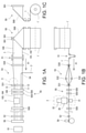
- FIG. 1A is a schematic plan view of an exemplary bag making machine
- FIG. 1B is a front view of FIG. 1A
- FIG. 1C is a side view of FIG. 1A
- 2A is an enlarged plan view of the area S of FIG. 1A
- FIG. 2B is a rear view of FIG. 2A
- FIG. 2C is a partial plan view of the expansion roller in the area T of FIG. 2A
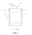
- FIG. 3 is a diagram showing the bag of FIG. 1A in detail. It is sectional drawing of the folded laminated film.
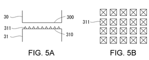
- FIG. 5A shows an exemplary horn and anvil
- FIG. 5B shows an exemplary sequence of protrusions of FIG. 5A. 6A-6C show exemplary ultrasonic welding.
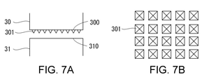
- FIG. 7A shows another exemplary horn and anvil
- FIG. 7B shows another exemplary sequence of protrusions of FIG. 7A
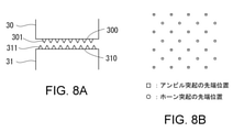
- FIG. 8A shows another exemplary horn and anvil
- FIG. 8B illustrates the positional relationship between the tip of the horn protrusion and the tip of the anvil protrusion.
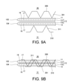
- 9A and 9B show another exemplary ultrasonic welding.
- 10A, 10B show another exemplary projection
- FIGS. 10C, 10D show another exemplary arrangement of protrusions.
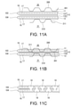
- 11A-11C show another exemplary ultrasonic welding.
- 12A is a plan view of an exemplary bag
- FIG. 12B is an enlarged view of the region P of FIG. 12A
- FIG. 12C is a sectional view taken along line QQ of FIG.
- FIG. 12B and FIG. 12D is a cross-sectional view of FIG. 12B. It is a cross-sectional view taken along the line RR.
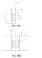
- FIG. 13A shows an exemplary ultrasonic welding region in the bag and
- FIG. 13B shows an exemplary ultrasonic welding region in the web.
- 14A, 14B show yet another exemplary ultrasonic welding region in the bag.
- FIGS. 1A-1C An exemplary bag making machine is shown in FIGS. 1A-1C.
- Bags 10 (FIG. 1A) are sequentially manufactured by a bag making machine.
- the web 1 is continuously fed from the original fabric 1'in its length direction (its continuous direction) at a constant speed, and is folded in half by the first folding device 50.
- the first folding device 50 includes a triangular plate 500 and a pair of grip rollers 501.
- the web 1 is folded in half along the longitudinal center line by the triangular plate 500 and the grip roller 501 during transportation.
- Reference numeral 100 in FIG. 1A indicates a folding edge resulting from the folding of the web 1.
- Reference numerals 101 and 102 in FIG. 1A indicate both sides of the web 1 aligned with each other by folding the web 1 in half.
- the folded web 1 is then appropriately switched from continuous transport to intermittent transport by a dancer device 51 including a dancer roller.
- a transport device 52 including a pair of transport rollers is provided in the downstream portion of the bag making machine, and the web 1 is intermittently transported in the length direction of the web 1.
- the transport direction of the web 1 is indicated by reference numeral X1.
- the web 1 is then further folded by a second folding device 53 to include two continuous body portions 11, 12 and a continuous gusset portion 13 folded between these body portions 11, 12. , Made from web 1.
- the second folding device 53 includes a pair of expansion rollers 532 (FIG. 1B) arranged downstream of the pair of guide rollers 530 and upstream of the pair of guide rollers 531.
- the web 1 is expanded by the expansion roller 532 in the section from the guide roller 530 to the guide roller 531 to provide a space between the two layers of the web 1.
- the second folding device 53 is further provided with a first forming plate 533 provided downstream of the expansion roller 532 and a second forming plate 533 provided following the downstream of the first forming plate 533.
- a forming plate 534 is provided.
- the first forming plate 533 has a trapezoidal shape.
- the first forming plate 533 is arranged in the space formed by the expansion roller 532 so as to abut from the inside of the web 1 on the portion including the bent edge 100 of the web 1.
- the first forming plate 533 is oriented so as to narrow toward the downstream.
- the second forming plate 534 has a triangular shape.
- the second forming plate 534 is arranged so as to abut from the outside on the portion including the bent edge 100.
- the second forming plate 534 narrows toward the downstream and toward the web 1, and one apex 5340 (FIG. 2B) becomes the downstream end of the second forming plate 534 and enters the web 1 and approaches the guide roller 531. , Contact the bent edge 100 of the web 1.
- the portion including the bent edge 100 is guided to the second forming plate 534 in a state of being expanded by the first forming plate 533, and then between the two layers of the web 1 by the second forming plate 534. It is folded back in the opposite direction along the bending edge 100 so as to enter. Then, in that state, the web 1 passes between the pair of guide rollers 531.
- the portion including the bent edge 100 is folded between the two layers of the web 1 resulting in a continuous gusset portion 13, and the two layers of the web 1 are two continuous trunk portions. It becomes 11 and 12.
- the bent edge 100 becomes the inner edge of the gusset portion 13.
- the gusset portion 13 is divided into two portions 131 and 132 (see FIG. 4) by its inner edge 100.
- Reference numerals 103 and 104 in FIG. 2A indicate the outer edge of the gusset portion 13, and this outer edge is also the boundary edge between the gusset portion 13 and the body portions 11 and 12.
- the web 1 is conveyed in such a folded state.
- FIG. 2C shows an enlarged view of the expansion roller 532 in the region T of FIG. 2A.
- each expansion roller 532 may have an R-shaped end 5320. Then, the end portion 5320 may be located on the folded side of the web 1 so as to be in contact with the inner surface of the web 1 to prevent the web 1 from being damaged.
- the continuous strip member 2 (FIG. 1A) is inserted between the two layers of the web 1 (hence, the torso 11 and 12) through the space secured by the expansion roller 532. good.
- the band-shaped member 2 of the embodiment may be a part that allows the bag 10 to be repeatedly opened and closed, and specifically, is a zipper made of a male material and a female material that are detachably fitted to each other.
- the zipper 2 is guided by the guide roller 54 with the male and female materials fitted to each other, turned around, and inserted between the body portions 11 and 12.
- the zipper 2 may be inserted between the body portions 11 and 12 and then irradiated with a laser by a laser device (not shown) and welded to the body portions 11 and 12. Therefore, the male material may be laser welded to the inner surface of the body portion 11/12, and the female material may be laser welded to the inner surface of the body portion 12/11.
- the laser device for welding may be disclosed in, for example, Japanese Patent Application Laid-Open No. 2017-47622. Instead of such a laser method, a heat sealing method may be adopted.
- the configuration of the bag 10 becomes complicated, the number of steps for incorporating or forming additional parts such as strip-shaped members, gussets, and spouts increases. As a result, the entire bag making process becomes complicated, but there is a concern that the bag making speed may decrease. For proper speed improvement, it is important to balance the specific process so that it does not become a bottleneck. For example, in the case of bag making including the welding process of the heat-sealing type zipper 2, if the welding of the heat-sealing type zipper 2 is the bottleneck, the laser method is used as the welding of the zipper 2 as in the present embodiment. Adopt to improve bag making speed.
- the heat sealing device 55 may include a plurality of sealing units 550. In the embodiment, three seal units 550 are provided, each including a pair of heated heat seal bars.
- the number of seal units 550 may be determined according to characteristics such as bag making speed.
- the plurality of seal units 550 may sequentially heat-seal the same portion to provide a high-quality heat seal at high speed, or may heat-seal different portions.
- the web 1 of the embodiment is a laminated film including a base material layer 16 made of a base material and a sealant layer 17 made of a sealant having a melting point lower than that of the base material.
- the base material may be, for example, nylon, PET, or the like.
- the sealant may be, for example, polyethylene, polypropylene or the like.
- the base material layer 16 forms the first surface of the web 1, and the sealant layer 17 forms the second surface of the web 1.
- the outer surface of the web 1 (hence the torso 11, 12 and the gusset 13) is formed by the substrate layer 16, and the inner surface of the web 1 (hence the torso 11, 12 and the gusset 13) is formed by the sealant layer 17.
- the web 1 is folded by the folding devices 50 and 53. Then, heat sealing is performed by utilizing the melting of the sealant of the sealant layer 17.
- the heat seal device 55 heat-seals the body portions 11 and 12 to each other in a region where they do not sandwich the gusset portion 13, and heat-seals the body portion 11 and the gusset portion 13 (part 131) to each other.
- the portion 12 and the gusset portion 13 (part 132) are heat-sealed with each other.
- the outer surfaces (opposing surfaces) of the portions 131 and 132 of the gusset portion 13 are formed of the base material layer 16, they are not heat-sealed by the heat-sealing device 55.
- the portions 131 and 132 are ultrasonically welded to each other by the ultrasonic welding device 3 each time the web 1 is intermittently conveyed.
- an ultrasonically welded region 15 (not shown in FIG. 1A, see FIG. 3) (hereinafter referred to as an ultrasonic welded region) is generated on the web 1 at a pitch corresponding to the width of the bag 10.
- the ultrasonic welding region 15 is internally included in the heat seal region 14.
- the ultrasonic welding device 3 is arranged downstream of the two seal units 550 and upstream of one seal unit 550.
- the web 1 is heat-sealed twice at the same location by two seal units 550 upstream of the ultrasonic welding device 3, thereby softening the body portions 11, 12 and the gusset portion 13.
- the ultrasonic welding device 3 performs ultrasonic welding on the body portions 11 and 12 and the gusset portion 13 in a softened and lightly attached state.
- the ultrasonic welding device 3 and the welding method using the ultrasonic welding device 3 will be described in detail later.
- the relative positional relationship of the ultrasonic welding device 3 with the heat sealing device 55 (sealing unit 550) is arbitrary, and may be appropriately determined according to the material of the web 1 (bag 10), the purpose of welding, and the like. Further, the order of ultrasonic welding and heat sealing may be appropriately determined according to the material of the web 1 (bag 10), the purpose of welding, and the like.
- the web 1 and zipper 2 are placed in the heat sealing region 14 in the width direction of the web 1 by a crosscut device 56 including a cutter, a cradle, etc. at each intermittent feed of the web 1. At the position, it is cross-cut across the ultrasonic welding region 15. As a result, the bags 10 are sequentially manufactured.
- FIG. 3 shows an enlarged view of the bag 10 of FIG. 1A.
- the bag 10 can be repeatedly opened and closed by the zipper 2.
- the body portions 11 and 12 and the gusset portion 13 are integrally formed by a single sheet separated from the web 1.
- the edges 101, 102 define the opening of the bag 10.
- the gusset portion 13 functions as a bottom gusset portion. Since the areas 14 and 15 are divided into two by the cross cut, they are located on both sides of the bag 10.
- the ultrasonic welding device 3 and the method of ultrasonically welding the portions 131 and 132 of the gusset portion 13 to each other using the ultrasonic welding device 3 will be described.
- the ultrasonic welding device 3 includes a horn 30 and an anvil 31 provided so as to face each other.
- the ultrasonic welding device 3 further includes a drive device 32 configured to move the horn 30 closer to and further from the anvil 31 and ultrasonically vibrate the horn 30.
- the horn 30 and the anvil 31 face each other up and down with the web 1 during intermittent transportation in between. Specifically, the horn 30 and the anvil 31 face each other with the body portions 11 and 12 and the gusset portion 13 folded between them in between.
- the body portions 11, 12 and the gusset portion 13 are sandwiched and pressurized by the horn 30 and the anvil 31.
- the horn 30 is vibrated at high frequencies by the drive device 32.
- the energy of ultrasonic vibration is transmitted to a portion to be welded (hereinafter referred to as a target location) and converted into frictional heat at the target location.
- the members are welded to each other at the target location due to the temperature rise due to the frictional heat.
- the gusset portion 13 is made of a single material such as polyethylene, the facing surfaces of the portions 131 and 132 are welded to each other.
- the gusset portion 13 is a laminated film in which the facing surfaces of the portions 131 and 132 are formed of a base material layer, the protrusions 311 of the anvil 31 and / or the protrusions 301 of the horn 30 (FIGS. 5A and 7A, which will be described later).
- the base material layer is broken by (see FIG. 8A and the like), and the sealant layer of the laminated film is melted, so that the facing surfaces of the portions 131 and 132 are substantially welded to each other.
- the ultrasonic welding conditions including frequency, amplitude, vibration time, pressing force, etc. are appropriately selected according to the material of the welded portions 131 and 132, the required welding strength, and the like.
- the horn 30 includes a flat facing surface 300 facing the anvil 31.
- the anvil 31 includes a flat facing surface 310 facing the horn 30 and a plurality of protrusions 311 protruding from the facing surface 310.
- the protrusion 311 may be pointed. As shown in the plan view of FIG. 5B, the protrusions 311 may be arranged two-dimensionally.
- the protrusion 311 penetrates at least the outer substrate layer 16 of the web 1. Then, it penetrates into the inner sealant layer 17. More specifically, the protrusion 311 is pierced into the body portion 11, 12 and the portion 131, 132 until it penetrates the body portion 12 and the portions 131, 132 of the gusset portion 13 and reaches the opposite body portion 11. .. Then, in that state, the horn 30 is ultrasonically vibrated. By this ultrasonic vibration, the portions 131 and 132 are ultrasonically welded to each other as shown in FIG. 6C.
- the protrusion 311 Since the protrusion 311 has entered the laminated portion consisting of the body portions 11, 12 and the gusset portion 13, the distance between the horn 30 and the anvil 31 is shortened, and therefore the distance between the horn 30 / anvil 31 and the target portion is shortened. The distance is shortened. As a result, the vibration energy is efficiently transmitted to the target location, and the temperature of the target location rises in a short time. Therefore, the protrusion 311 improves the efficiency of ultrasonic welding.
- the heat seal by the seal unit 550 softens the web 1 (its base material layer 16) before the ultrasonic welding. This facilitates the entry of the protrusion 311 into the web 1, specifically the piercing.
- the sealant of the sealant layer 17 is melted by the ultrasonic vibration of the horn 30 and flows into each through hole of the base material layer 16. It is squeezed and filled, and as shown in FIG. 6C, a sealant filling portion 18 is formed.
- the filling portions 18 integrally weld the body portions 11, 12 and the portions 131, 132, thereby improving the welding strength of the ultrasonic welding region 15.
- a plurality of protrusions 301 may be two-dimensionally arranged so as to project from the facing surface 300 of the horn 30 instead of the facing surface 310 of the anvil 31. This also makes it possible to achieve the above effect.
- both the horn 30 and the anvil 31 may be provided with protrusions 301 and 311.
- the protrusions 301 of the horn 30 and the protrusions 311 of the anvil 31 are arranged so as to be offset from each other in a direction perpendicular to their facing directions so that their tips do not face each other.
- both the horn 30 and the anvil 31 have protrusions 301 and 311, more efficient ultrasonic welding can be performed.
- the protrusions 301/311 may have a square pyramid shape.
- the base of the square pyramid may be a rectangle (including a square) (FIG. 5B, FIG. 7B) or a rhombus (FIG. 10A).
- the protrusions 301/311 may have a polygonal pyramid shape other than the square pyramid, respectively.
- the protrusions 301/311 may be conical as shown in FIG. 10B.
- the protrusions 301/311 may be regularly arranged in the vertical and horizontal directions, for example, in a matrix, as shown in FIGS. 5B, 7B, 10C, and 10D. As shown in FIGS. 10C and 10D, for example, the protrusions 301/311 may be oriented so that the diagonal line of the bottom surface of the protrusions 301/311 is slanted with respect to the vertical and horizontal directions of the arrangement of the protrusions 301 / 311.
- the plurality of protrusions 301 may have different orientations from each other, and the plurality of protrusions 311 may have different orientations from each other.
- a protrusion 301/311 having a flat tip may be used.
- both the horn 30 and the anvil 31 are provided with protrusions 301, 311 having a flat tip.
- the protrusions 301, 311 are recessed into the laminated portion composed of the body portions 11, 12 and the gusset portion 13. Then, ultrasonic welding is performed by the ultrasonic vibration of the horn 30.
- FIG. 12A is a front view of the bag 10. After the shape of the bag 10 is completed by cross-cutting, a step of filling the contents may be carried out.
- the weight of the contents in the bag 10 exerts a force F (FIG. 12D) that tends to separate the gusset portions 13 (bottom gusset portions) portions 131 and 132 from each other in the ultrasonic welding region 15. As shown in FIG. 12B, this force F is larger in the outward component F1 of the bag 10 than in the vertical component F2 of the bag 10.
- the ultrasonic welding between the portions 131 and 132 opposes the force F that separates these portions 131 and 132.
- the strength of ultrasonic welding increases in proportion to the ratio of the welded portion in the cross section perpendicular to the direction of the component F1. Therefore, in the case of the semicircular ultrasonic welding region 15 as shown in FIG. 12B, the strength of ultrasonic welding is higher at the position of the line M than at the position of the line L.
- the ultrasonic welding region 15 is the bag as shown in FIG. 13A. It is preferable to have the length dimension L1 inside the bag, which is larger than the length dimension L2 on the outside (L1> L2). As shown in FIG. 13A, the ultrasonic welding region 15 of the bag 10 may have a trapezoidal shape that narrows toward the outside of the bag.
- the ultrasonic welding region 15 of FIG. 12B and the ultrasonic welding region 15 of FIG. 13A have the same area
- the ultrasonic welding region 15 of FIG. 13A has the same weight as that of FIG. 12B. Stronger against peeling by.
- the shapes of the facing surfaces 300 and 310 of the horn 30 and the anvil 31 are determined so that the ultrasonic welding region 15 of FIG. 13B is formed on the web 1 by the ultrasonic welding device 3 (FIG. 1A).
- the web 1 is cross-cut at the cross-cut position 560 by the cross-cut device 56 (FIG. 1A), and the ultrasonic welding region 15 is divided into two.
- the bag 10 having the trapezoidal ultrasonic welding region 15 is manufactured.
- the corner of the ultrasonic welding region 15 May have an R shape.
- the ultrasonic welding region 15 is not limited to the trapezoidal shape as shown in FIG. 14A, but may be a square shape having R-shaped corners as shown in FIG. 14B.
- the ultrasonic welding region 15 of FIGS. 14A and 14B may also be formed by the method described in FIG. 13B.
- the projection 301/311 improves the efficiency of ultrasonic welding.
- the welding method may be applied not to the web 1 but to the body portion 11, the body portion 12, and the gusset portion 13 integrally formed by folding a single-leaf sheet. Further, the welding method may be applied to the body portion 11, the body portion 12, and the gusset portion 13 as separate parts.
- the gusset portion 13 may function as a heaven gusset portion instead of the bottom gusset portion.
- the welding method may be applied to the side gusset portion folded into the body portions 11 and 12 as in Patent Document 1.
- a material having thermoplasticity may be widely used in addition to the laminated film including the base material layer 16 and the sealant layer 17 as in the embodiment.
- a monomaterial material that is superior to recycling may be used.
- a material that can reduce the amount of resin discarded such as a material composed of paper as a base material and a resin coated on the paper, may be used.
- a biodegradable material may be used.
Landscapes
- Engineering & Computer Science (AREA)
- Mechanical Engineering (AREA)
- Chemical & Material Sciences (AREA)
- Composite Materials (AREA)
- Making Paper Articles (AREA)
Abstract
According to the present invention, at least one among a horn and an anvil comprises a plurality of protrusions protruding from a facing surface thereof. Two body parts and a gusset part folded between the body parts are sandwiched and pressed by the horn and the anvil. Two portions of the gusset part are welded to each other by ultrasonic vibrations from the horn between sandwiching and pressing.
Description
本願は、2つの胴部の間に折り込まれたガセット部の2つの部分を互いに溶着することを含む製袋方法および溶着方法に関する。
The present application relates to a bag making method and a welding method including welding two parts of a gusset part folded between two body parts to each other.
プラスチック袋、パウチのような袋は、例えば、互いに対向する2つの胴部を備える。袋は、その容量の拡大のために、または、袋の自立性を得るために、胴部の間に折り込まれたガセット部を備える。
A plastic bag, a bag such as a pouch, for example, has two torso facing each other. The bag comprises a gusset that is folded between the torso to increase its capacity or to gain the independence of the bag.
ガセット部は、例えば、サイドガセット部、底ガセット部、または天ガセット部である。ガセット部は、その折曲縁によって2つの部分に区画されている。例えば、2つの部分を袋の端において互いに溶着して、袋が過剰に拡大することを防いだり、袋の自立性を強化したりすることがある。袋の自立性を強化する理由は、袋を載置面に置く際、袋と当該載置面との接触部を構成するのはガセット部(底ガセット部)の両端縁であり、内容物が充填されていれば、当該両端縁は一直線ではなく、所定の面積を有する領域の外周縁として当該載置面に接触するからである。
The gusset part is, for example, a side gusset part, a bottom gusset part, or a heaven gusset part. The gusset portion is divided into two parts by its bent edge. For example, the two parts may be welded together at the edge of the bag to prevent the bag from expanding excessively or to enhance the bag's independence. The reason for enhancing the independence of the bag is that when the bag is placed on the mounting surface, the contact portion between the bag and the mounting surface is composed of both ends of the gusset portion (bottom gusset portion), and the contents are This is because, if filled, the edges of both ends are not in a straight line and come into contact with the mounting surface as the outer peripheral edge of a region having a predetermined area.
特許文献1は、ガセット部の2つの部分を互いに超音波溶着する方法を開示する。特許文献1の方法は、ホーンを一方の胴部に接触させアンビルを他方の胴部に接触させて、これら2つの胴部およびこれらの胴部の間に折り込まれたガセット部をホーンおよびアンビルで挟持および加圧する。そして、ホーンの超音波振動によって、ガセット部の2つの部分を互いに溶着する。
Patent Document 1 discloses a method of ultrasonically welding two portions of a gusset portion to each other. In the method of Patent Document 1, the horn is brought into contact with one body portion and the anvil is brought into contact with the other body portion, and the two body portions and the gusset portion folded between these body portions are formed with the horn and the anvil. Hold and pressurize. Then, the two parts of the gusset portion are welded to each other by the ultrasonic vibration of the horn.
このような超音波溶着を実施するとき、ホーン・アンビルとガセット部との間に位置する胴部が、ホーンから溶着されるべき箇所への振動エネルギーの伝達効率を下げる要因となる。したがって、ガセット部の2つの部分がしっかりと互いに溶着されないことがある。
When performing such ultrasonic welding, the body portion located between the horn anvil and the gusset portion becomes a factor that lowers the transmission efficiency of vibration energy from the horn to the portion to be welded. Therefore, the two portions of the gusset portion may not be firmly welded to each other.
本願は、ガセット部の2つの部分を効率的に溶着する製袋方法および溶着方法を提供することを目的とする。
An object of the present application is to provide a bag making method and a welding method for efficiently welding two parts of a gusset portion.
本願の一態様によれば、製袋方法が提供され、
前記製袋方法は:
ウェブを折って、連続状の第1胴部、連続状の第2胴部、および、連続状のガセット部を前記ウェブから形成すること、を備え、前記ガセット部は、前記第1および第2胴部の間に折り込まれており;
前記第1胴部、前記第2胴部、および、前記第1および第2胴部の間に折り込まれた前記ガセット部を、ホーンおよびアンビルで挟持および加圧すること、を備え、前記ホーンは、前記アンビルに対向する対向面を備え、前記アンビルは、前記ホーンに対向する対向面を備え、前記ホーンおよび前記アンビルのうち少なくともいずれか一方は、その前記対向面から突出する複数の突起を備え;
前記第1胴部、前記第2胴部、および、前記ガセット部が前記ホーンおよび前記アンビルで挟持および加圧されている間の前記ホーンの超音波振動によって、前記ガセット部の第1部分と第2部分とを互いに溶着すること、を備え;および、
前記第1部分および前記第2部分が前記ホーンおよび前記アンビルで互いに超音波溶着された超音波溶着領域を横切って、前記ウェブを、前記ウェブの幅方向にクロスカットして、袋を製造すること、を備える。 According to one aspect of the present application, a bag making method is provided.
The bag making method is:
The web is folded to form a continuous first torso, a continuous second torso, and a continuous gusset from the web, wherein the gussets are the first and second. Folded between the torso;
The horn comprises sandwiching and pressurizing the first torso, the second torso, and the gusset folded between the first and second torso with a horn and anvil. The anvil has a facing surface facing the anvil, the anvil has an opposing surface facing the horn, and at least one of the horn and the anvil has a plurality of protrusions protruding from the facing surface;
The first and first parts of the gusset are due to ultrasonic vibrations of the horn while the first body, the second body, and the gusset are sandwiched and pressurized by the horn and the anvil. Provided to weld the two parts to each other; and
A bag is manufactured by cross-cutting the web in the width direction of the web, with the first portion and the second portion crossing an ultrasonic welding region in which the horn and the anvil are ultrasonically welded to each other. , Equipped with.
前記製袋方法は、袋外方における長さ寸法よりも大きい袋内包における長さ寸法を有する前記超音波溶着領域を備える前記袋を製造すること、を備えてよい。
The bag making method may include manufacturing the bag having the ultrasonic welding region having a length dimension in the bag inclusion larger than the length dimension outside the bag.
前記製袋方法は、袋外方に向って窄まる台形形状の前記超音波溶着領域を備える前記袋を製造すること、を備えてよい。
The bag making method may include manufacturing the bag having the trapezoidal ultrasonic welding region that narrows toward the outside of the bag.
前記製袋方法は、前記ガセット部を底ガセット部として備える前記袋を製造すること、を備えてよい。
The bag making method may include manufacturing the bag having the gusset portion as a bottom gusset portion.
前記製袋方法は、前記ホーンおよび前記アンビルを用いた超音波溶着の際に生じた前記複数の突起の痕を有する前記袋を製造すること、を備えてよい。
The bag making method may include manufacturing the bag having the marks of the plurality of protrusions generated during ultrasonic welding using the horn and the anvil.
また、本願の別の態様によれば、第1胴部と第2胴部との間に折りこまれたガセット部の第1部分および第2部分を互いに超音波溶着する溶着方法が提供され、
前記溶着方法は:
前記第1胴部、前記第2胴部、および、前記第1および第2胴部の間に折り込まれた前記ガセット部をホーンおよびアンビルで挟持および加圧すること、を備え、前記ホーンは、前記アンビルに対向する対向面を備え、前記アンビルは、前記ホーンに対向する対向面を備え、前記アンビルまたは前記ホーンの少なくともいずれか一方は、その前記対向面から突出する複数の突起を備え;および、
前記第1胴部、前記第2胴部、および、前記ガセット部が前記ホーンおよび前記アンビルで挟持および加圧されている間の前記ホーンの超音波振動によって、前記第1部分および前記第2部分を互いに溶着すること、を備える。 Further, according to another aspect of the present application, there is provided a welding method in which the first portion and the second portion of the gusset portion folded between the first body portion and the second body portion are ultrasonically welded to each other.
The welding method is:
The horn comprises sandwiching and pressurizing the first torso, the second torso, and the gusset folded between the first and second torso with a horn and anvil. The anvil has a facing surface facing the anvil, the anvil has an opposing surface facing the horn, and at least one of the anvil or the horn has a plurality of protrusions protruding from the facing surface;
The first and second parts due to ultrasonic vibrations of the horn while the first body, the second body, and the gusset are sandwiched and pressurized by the horn and the anvil. To be welded to each other.
前記複数の突起は、尖状でよい。
前記溶着方法は、
前記第1胴部、前記第2胴部、および、前記ガセット部が前記ホーンおよび前記アンビルで挟持および加圧される際に、前記複数の突起を、前記第1または第2胴部を貫通するように、前記第1または第2胴部、および、前記ガセット部に突刺することを備えてよい。 The plurality of protrusions may be pointed.
The welding method is
When the first body portion, the second body portion, and the gusset portion are sandwiched and pressed by the horn and the anvil, the plurality of protrusions penetrate the first or second body portion. As such, it may be provided to pierce the first or second body portion and the gusset portion.
前記溶着方法は、
前記第1胴部、前記第2胴部、および、前記ガセット部が前記ホーンおよび前記アンビルで挟持および加圧される際に、前記複数の突起を、前記第1胴部、前記第1部分、および、前記第2部分を貫通するように、前記第1胴部、前記第2胴部、前記第1部分、および、前記第2部分に突刺することを備えてよい。 The welding method is
When the first body portion, the second body portion, and the gusset portion are sandwiched and pressed by the horn and the anvil, the plurality of protrusions are formed on the first body portion, the first portion, and the like. And, it may be provided to pierce the first body portion, the second body portion, the first portion, and the second portion so as to penetrate the second portion.
前記複数の突起は、フラットな先端を備えてよい。
前記溶着方法は、
前記第1胴部、前記第2胴部、および、前記ガセット部が前記ホーンおよび前記アンビルで挟持および加圧される際に、前記複数の突起を、前記第1胴部、前記第2胴部、前記第1部分、および、前記第2部分からなる積層部分にめり込ませることを備えてよい。 The plurality of protrusions may have a flat tip.
The welding method is
When the first body portion, the second body portion, and the gusset portion are sandwiched and pressed by the horn and the anvil, the plurality of protrusions are formed on the first body portion and the second body portion. , The first portion and the laminated portion including the second portion may be provided to be recessed.
前記第1胴部、前記第2胴部、および、前記ガセット部は、それぞれ、基材からなる基材層、および、前記基材よりも融点の低いシーラントからなるシーラント層を含むラミネートフィルムでよい。
前記溶着方法は、
前記ホーンの超音波振動により前記シーラントを溶融させて、前記第1胴部、前記第2胴部、前記第1部分、および、前記第2部分を、前記シーラントを用いて一体的に溶着すること、を備えてよい。 The first body portion, the second body portion, and the gusset portion may be a laminated film including a base material layer made of a base material and a sealant layer made of a sealant having a melting point lower than that of the base material, respectively. ..
The welding method is
The sealant is melted by the ultrasonic vibration of the horn, and the first body portion, the second body portion, the first part, and the second part are integrally welded using the sealant. May be equipped with.
前記溶着方法は、
ウェブを折って、前記第1胴部、前記第2胴部、および、前記ガセット部を前記ウェブから形成することを備えてよい。ここで、前記第1胴部、前記第2胴部、および、前記ガセット部は、連続状であり、一体形成されてよい。 The welding method is
The web may be folded to form the first torso, the second torso, and the gusset from the web. Here, the first body portion, the second body portion, and the gusset portion are continuous and may be integrally formed.
前記第1胴部、前記第2胴部、および、前記ガセット部は、別々のパーツであってもよい。
The first body portion, the second body portion, and the gusset portion may be separate parts.
前記複数の突起は、前記ホーンの前記対向面および前記アンビルの前記対向面の双方に設けられてよい。前記ホーンの前記突起および前記アンビルの前記突起は、前記ホーンの前記突起の先端と前記アンビルの前記突起の先端とが互いに対向しないように、前記ホーンおよび前記アンビルの対向方向に直角な方向に互いにオフセットされて配置されてよい。
The plurality of protrusions may be provided on both the facing surface of the horn and the facing surface of the anvil. The protrusion of the horn and the protrusion of the anvil are oriented at right angles to the opposite direction of the horn and the anvil so that the tip of the protrusion of the horn and the tip of the protrusion of the anvil do not face each other. It may be arranged offset.
以下、図面を参照して、本願の実施形態が説明される。
Hereinafter, embodiments of the present application will be described with reference to the drawings.
例示の製袋機が、図1A-図1Cに示されている。袋10(図1A)が、製袋機によって順次製造される。ウェブ1が、原反1’からその長さ方向(その連続方向)に定速で連続的に繰り出され、第1折り装置50によって2つ折りされる。第1折り装置50は、三角板500と、一対のくわえローラ501とを備える。ウェブ1は、三角板500、および、くわえローラ501によって、搬送の際に、その長手方向中心線に沿って2つ折りされていく。図1Aの符号100は、ウェブ1の2つ折りの結果生じる折曲縁を示す。図1Aの符号101,102は、ウェブ1の2つ折りによって互いに整合したウェブ1の両側縁を示す。
An exemplary bag making machine is shown in FIGS. 1A-1C. Bags 10 (FIG. 1A) are sequentially manufactured by a bag making machine. The web 1 is continuously fed from the original fabric 1'in its length direction (its continuous direction) at a constant speed, and is folded in half by the first folding device 50. The first folding device 50 includes a triangular plate 500 and a pair of grip rollers 501. The web 1 is folded in half along the longitudinal center line by the triangular plate 500 and the grip roller 501 during transportation. Reference numeral 100 in FIG. 1A indicates a folding edge resulting from the folding of the web 1. Reference numerals 101 and 102 in FIG. 1A indicate both sides of the web 1 aligned with each other by folding the web 1 in half.
2つ折りされたウェブ1は、次いで、ダンサーローラを含むダンサー装置51によって連続搬送から間欠搬送に適切に切り替えられる。なお、一対の搬送ローラを含む搬送装置52が、製袋機の下流部分に設けられ、ウェブ1を当該ウェブ1の長さ方向に間欠的に搬送している。ウェブ1の搬送方向は、符号X1によって示される。
The folded web 1 is then appropriately switched from continuous transport to intermittent transport by a dancer device 51 including a dancer roller. A transport device 52 including a pair of transport rollers is provided in the downstream portion of the bag making machine, and the web 1 is intermittently transported in the length direction of the web 1. The transport direction of the web 1 is indicated by reference numeral X1.
次いで、ウェブ1は、第2折り装置53によってさらに折られて、2つの連続状の胴部11,12、および、これらの胴部11,12の間に折り込まれた連続状のガセット部13が、ウェブ1から形成されるようにする。
The web 1 is then further folded by a second folding device 53 to include two continuous body portions 11, 12 and a continuous gusset portion 13 folded between these body portions 11, 12. , Made from web 1.
第2折り装置53は、一対のガイドローラ530の下流かつ一対のガイドローラ531の上流に配置された一対の拡張ローラ532(図1B)を備える。ウェブ1が、拡張ローラ532によって、ガイドローラ530からガイドローラ531までの区間で拡げられ、ウェブ1の2層の間に空間が設けられる。
The second folding device 53 includes a pair of expansion rollers 532 (FIG. 1B) arranged downstream of the pair of guide rollers 530 and upstream of the pair of guide rollers 531. The web 1 is expanded by the expansion roller 532 in the section from the guide roller 530 to the guide roller 531 to provide a space between the two layers of the web 1.
図2A,図2Bの通り、第2折り装置53は、さらに、拡張ローラ532の下流に続いて設けられた第1形成板533と、第1形成板533の下流に続いて設けられた第2形成板534とを備える。
As shown in FIGS. 2A and 2B, the second folding device 53 is further provided with a first forming plate 533 provided downstream of the expansion roller 532 and a second forming plate 533 provided following the downstream of the first forming plate 533. A forming plate 534 is provided.
第1形成板533は、台形形状を有する。第1形成板533は、ウェブ1の折曲縁100を含む部分にウェブ1の内側から当接するように、拡張ローラ532によって形成された空間内に配置されている。第1形成板533は、下流に向って窄まるように配向されている。
The first forming plate 533 has a trapezoidal shape. The first forming plate 533 is arranged in the space formed by the expansion roller 532 so as to abut from the inside of the web 1 on the portion including the bent edge 100 of the web 1. The first forming plate 533 is oriented so as to narrow toward the downstream.
第2形成板534は、三角形状を有する。第2形成板534は、折曲縁100を含む部分に、外側から当接するように配置されている。第2形成板534は、下流に向ってかつウェブ1に向って窄まり、その1つの頂点5340(図2B)が第2形成板534の下流端となりウェブ1に入り込み、ガイドローラ531に接近し、ウェブ1の折曲縁100と当接する。
The second forming plate 534 has a triangular shape. The second forming plate 534 is arranged so as to abut from the outside on the portion including the bent edge 100. The second forming plate 534 narrows toward the downstream and toward the web 1, and one apex 5340 (FIG. 2B) becomes the downstream end of the second forming plate 534 and enters the web 1 and approaches the guide roller 531. , Contact the bent edge 100 of the web 1.
ウェブ1の搬送に伴い、折曲縁100を含む部分が、第1形成板533によって拡げられた状態で第2形成板534へ案内され、次いで第2形成板534によってウェブ1の2層の間に入り込むように折曲縁100に沿って反対方向に折り返される。そして、その状態で、ウェブ1が、一対のガイドローラ531の間を通過する。
Along with the transportation of the web 1, the portion including the bent edge 100 is guided to the second forming plate 534 in a state of being expanded by the first forming plate 533, and then between the two layers of the web 1 by the second forming plate 534. It is folded back in the opposite direction along the bending edge 100 so as to enter. Then, in that state, the web 1 passes between the pair of guide rollers 531.
これによって、折曲縁100を含む部分は、ウェブ1の2層の間に折り込まれ、その結果、連続状のガセット部13となり、そして、ウェブ1の2層は、2つの連続状の胴部11,12になる。折曲縁100がガセット部13の内側縁になる。ガセット部13は、その内側縁100によって、2つの部分131,132(図4参照)に区画される。図2Aの符号103,104は、ガセット部13の外側縁を示し、この外側縁は、ガセット部13と胴部11,12との境界縁でもある。以下、ウェブ1は、このように折られた状態で搬送される。
Thereby, the portion including the bent edge 100 is folded between the two layers of the web 1 resulting in a continuous gusset portion 13, and the two layers of the web 1 are two continuous trunk portions. It becomes 11 and 12. The bent edge 100 becomes the inner edge of the gusset portion 13. The gusset portion 13 is divided into two portions 131 and 132 (see FIG. 4) by its inner edge 100. Reference numerals 103 and 104 in FIG. 2A indicate the outer edge of the gusset portion 13, and this outer edge is also the boundary edge between the gusset portion 13 and the body portions 11 and 12. Hereinafter, the web 1 is conveyed in such a folded state.
なお、第2形成板534の頂点5340のウェブ1への入込み寸法がガセット部13の折込み寸法である。図2Cは、図2Aの領域Tにおける拡張ローラ532を拡大して示す。図2Cの通り、各拡張ローラ532は、R形状の端部5320を有してよい。そして、当該端部5320が、ウェブ1の折り込まれる側に位置し、ウェブ1の内面に接触するようにし、それにより、ウェブ1が傷つくのを防止してよい。
The insertion dimension of the apex 5340 of the second forming plate 534 into the web 1 is the folding dimension of the gusset portion 13. FIG. 2C shows an enlarged view of the expansion roller 532 in the region T of FIG. 2A. As shown in FIG. 2C, each expansion roller 532 may have an R-shaped end 5320. Then, the end portion 5320 may be located on the folded side of the web 1 so as to be in contact with the inner surface of the web 1 to prevent the web 1 from being damaged.
図1A,図1Bの通り、連続状の帯状部材2(図1A)が、拡張ローラ532によって確保された空間を通じて、ウェブ1の2層(したがって、胴部11,12)の間に挿入されてよい。実施形態の帯状部材2は、袋10を繰り返し開閉可能にするパーツでよく、具体的には、互いに着脱可能に嵌合する雄材と雌材とからなるジッパである。ジッパ2は、雄材と雌材とが互いに嵌合した状態でガイドローラ54よって案内され、方向転換され、胴部11,12の間に挿入される。
As shown in FIGS. 1A and 1B, the continuous strip member 2 (FIG. 1A) is inserted between the two layers of the web 1 (hence, the torso 11 and 12) through the space secured by the expansion roller 532. good. The band-shaped member 2 of the embodiment may be a part that allows the bag 10 to be repeatedly opened and closed, and specifically, is a zipper made of a male material and a female material that are detachably fitted to each other. The zipper 2 is guided by the guide roller 54 with the male and female materials fitted to each other, turned around, and inserted between the body portions 11 and 12.
ジッパ2は、胴部11,12の間に挿入された後、レーザ装置(図示されない)によってレーザ照射されて胴部11,12に溶着されてよい。したがって、雄材が胴部11/12の内面にレーザ溶着され、雌材が胴部12/11の内面にレーザ溶着されてよい。溶着用のレーザ装置は、例えば、特開2017-47622号公報に開示のものでよい。このようなレーザ方式に代えて、ヒートシール方式が採用されてよい。
The zipper 2 may be inserted between the body portions 11 and 12 and then irradiated with a laser by a laser device (not shown) and welded to the body portions 11 and 12. Therefore, the male material may be laser welded to the inner surface of the body portion 11/12, and the female material may be laser welded to the inner surface of the body portion 12/11. The laser device for welding may be disclosed in, for example, Japanese Patent Application Laid-Open No. 2017-47622. Instead of such a laser method, a heat sealing method may be adopted.
袋10の構成が複雑になると、帯状部材、ガセット部、スパウトなどの追加のパーツを組み込むまたは形成する工程が増える。結果的に、製袋工程全体も複雑になるが、製袋速度の低下が懸念される。速度の適切な向上のために、特定の工程がボトルネックとならないようにバランスを図ることが重要である。例えば、ヒートシール方式のジッパ2の溶着工程を含む製袋の場合に、ヒートシール方式のジッパ2の溶着がボトルネックとなっていれば、本実施形態のようにジッパ2の溶着としてレーザ方式を採用して、製袋速度を向上させる。
As the configuration of the bag 10 becomes complicated, the number of steps for incorporating or forming additional parts such as strip-shaped members, gussets, and spouts increases. As a result, the entire bag making process becomes complicated, but there is a concern that the bag making speed may decrease. For proper speed improvement, it is important to balance the specific process so that it does not become a bottleneck. For example, in the case of bag making including the welding process of the heat-sealing type zipper 2, if the welding of the heat-sealing type zipper 2 is the bottleneck, the laser method is used as the welding of the zipper 2 as in the present embodiment. Adopt to improve bag making speed.
胴部11,12、および、ガセット部13の形成後、ウェブ1が、ウェブ1の間欠送りの度に、ヒートシール装置55によってウェブ1の幅方向にヒートシールされる。それによって、ヒートシールされた領域14(図1Aでは図示略、図3参照)(以下、ヒートシール領域)が袋10の幅に相当するピッチでウェブ1に生じる。ヒートシール装置55は、複数のシールユニット550を備えてよい。実施形態では、3つのシールユニット550が設けられており、それぞれ、加熱された一対のヒートシールバーを含む。
After the body portions 11, 12 and the gusset portion 13 are formed, the web 1 is heat-sealed in the width direction of the web 1 by the heat sealing device 55 each time the web 1 is intermittently fed. As a result, a heat-sealed region 14 (not shown in FIG. 1A, see FIG. 3) (hereinafter, heat-sealed region) is generated on the web 1 at a pitch corresponding to the width of the bag 10. The heat sealing device 55 may include a plurality of sealing units 550. In the embodiment, three seal units 550 are provided, each including a pair of heated heat seal bars.
シールユニット550の数は、製袋速度などの特性に従って決定されてよい。複数のシールユニット550が、同じ箇所を順次ヒートシールして、質の高いヒートシールを高速で提供してもよいし、異なる箇所をヒートシールしてもよい。
The number of seal units 550 may be determined according to characteristics such as bag making speed. The plurality of seal units 550 may sequentially heat-seal the same portion to provide a high-quality heat seal at high speed, or may heat-seal different portions.
図4の通り、実施形態のウェブ1は、基材からなる基材層16と、基材よりも融点の低いシーラントからなるシーラント層17を含むラミネートフィルムである。基材は、例えば、ナイロン、PETなどでよい。シーラントは、例えば、ポリエチレン、ポリプロピレンなどでよい。基材層16によってウェブ1の第1表面が形成され、シーラント層17によってウェブ1の第2表面が形成される。
As shown in FIG. 4, the web 1 of the embodiment is a laminated film including a base material layer 16 made of a base material and a sealant layer 17 made of a sealant having a melting point lower than that of the base material. The base material may be, for example, nylon, PET, or the like. The sealant may be, for example, polyethylene, polypropylene or the like. The base material layer 16 forms the first surface of the web 1, and the sealant layer 17 forms the second surface of the web 1.
ウェブ1(したがって、胴部11,12およびガセット部13)の外面が基材層16によって形成され、ウェブ1(したがって、胴部11,12およびガセット部13)の内面がシーラント層17によって形成されるように、ウェブ1が折り装置50,53によって折られている。そして、シーラント層17のシーラントの溶融を利用してヒートシールが実施される。
The outer surface of the web 1 (hence the torso 11, 12 and the gusset 13) is formed by the substrate layer 16, and the inner surface of the web 1 (hence the torso 11, 12 and the gusset 13) is formed by the sealant layer 17. As described above, the web 1 is folded by the folding devices 50 and 53. Then, heat sealing is performed by utilizing the melting of the sealant of the sealant layer 17.
したがって、ヒートシール装置55は、胴部11,12を、これらがガセット部13を挟んでいない領域で互いにヒートシールし、胴部11とガセット部13(部分131)とを互いにヒートシールし、胴部12とガセット部13(部分132)とを互いにヒートシールする。一方、ガセット部13の部分131,132は、その外面(対向面)が基材層16で形成されているので、ヒートシール装置55によって互いにヒートシールされない。
Therefore, the heat seal device 55 heat-seals the body portions 11 and 12 to each other in a region where they do not sandwich the gusset portion 13, and heat-seals the body portion 11 and the gusset portion 13 (part 131) to each other. The portion 12 and the gusset portion 13 (part 132) are heat-sealed with each other. On the other hand, since the outer surfaces (opposing surfaces) of the portions 131 and 132 of the gusset portion 13 are formed of the base material layer 16, they are not heat-sealed by the heat-sealing device 55.
部分131,132は、超音波溶着装置3によって、ウェブ1の間欠搬送の度に、互いに超音波溶着される。それによって、超音波溶着された領域15(図1Aで図示略、図3参照)(以下、超音波溶着領域)が、袋10の幅に相当するピッチでウェブ1に生じる。実施形態では、超音波溶着領域15は、ヒートシール領域14に内含される。
The portions 131 and 132 are ultrasonically welded to each other by the ultrasonic welding device 3 each time the web 1 is intermittently conveyed. As a result, an ultrasonically welded region 15 (not shown in FIG. 1A, see FIG. 3) (hereinafter referred to as an ultrasonic welded region) is generated on the web 1 at a pitch corresponding to the width of the bag 10. In the embodiment, the ultrasonic welding region 15 is internally included in the heat seal region 14.
超音波溶着装置3は、実施形態では、2つのシールユニット550の下流で1つのシールユニット550の上流に配置されている。ウェブ1が、超音波溶着装置3の上流の2つのシールユニット550によって同じ箇所を2回ヒートシールされ、これにより、胴部11,12およびガセット部13を軟化させる。超音波溶着装置3は、軟化して軽くくっついた状態の胴部11,12およびガセット部13に対して超音波溶着を実施する。超音波溶着装置3およびこれを用いた溶着方法は、後に詳述される。
In the embodiment, the ultrasonic welding device 3 is arranged downstream of the two seal units 550 and upstream of one seal unit 550. The web 1 is heat-sealed twice at the same location by two seal units 550 upstream of the ultrasonic welding device 3, thereby softening the body portions 11, 12 and the gusset portion 13. The ultrasonic welding device 3 performs ultrasonic welding on the body portions 11 and 12 and the gusset portion 13 in a softened and lightly attached state. The ultrasonic welding device 3 and the welding method using the ultrasonic welding device 3 will be described in detail later.
超音波溶着装置3のヒートシール装置55(シールユニット550)との相対位置関係は任意であり、ウェブ1(袋10)の材質や溶着の目的などに応じて適宜決定されてよい。また、超音波溶着とヒートシールとの順序も、ウェブ1(袋10)の材質や溶着の目的などに応じて適宜決定されてよい。
The relative positional relationship of the ultrasonic welding device 3 with the heat sealing device 55 (sealing unit 550) is arbitrary, and may be appropriately determined according to the material of the web 1 (bag 10), the purpose of welding, and the like. Further, the order of ultrasonic welding and heat sealing may be appropriately determined according to the material of the web 1 (bag 10), the purpose of welding, and the like.
ヒートシールおよび超音波溶着の後、ウェブ1およびジッパ2は、ウェブ1の間欠送りの度に、カッター、受台などを含むクロスカット装置56によって、ウェブ1の幅方向に、ヒートシール領域14の位置で、超音波溶着領域15を横切って、クロスカットされる。それによって、袋10が順次製造される。
After heat sealing and ultrasonic welding, the web 1 and zipper 2 are placed in the heat sealing region 14 in the width direction of the web 1 by a crosscut device 56 including a cutter, a cradle, etc. at each intermittent feed of the web 1. At the position, it is cross-cut across the ultrasonic welding region 15. As a result, the bags 10 are sequentially manufactured.
図3は、図1Aの袋10を拡大して示す。ジッパ2によって袋10は繰り返し開閉可能となる。胴部11,12およびガセット部13が、ウェブ1から切り離された1枚のシートによって一体形成されている。縁101,102によって袋10の開口が規定される。ガセット部13が底ガセット部として機能する。領域14,15は、クロスカットによって2分割されるので、袋10の両側に位置する。
FIG. 3 shows an enlarged view of the bag 10 of FIG. 1A. The bag 10 can be repeatedly opened and closed by the zipper 2. The body portions 11 and 12 and the gusset portion 13 are integrally formed by a single sheet separated from the web 1. The edges 101, 102 define the opening of the bag 10. The gusset portion 13 functions as a bottom gusset portion. Since the areas 14 and 15 are divided into two by the cross cut, they are located on both sides of the bag 10.
以下、超音波溶着装置3、および、これを用いてガセット部13の部分131,132を互いに超音波溶着する方法が説明される。
Hereinafter, the ultrasonic welding device 3 and the method of ultrasonically welding the portions 131 and 132 of the gusset portion 13 to each other using the ultrasonic welding device 3 will be described.
図1Bの通り、超音波溶着装置3は、互いに対向するように設けられたホーン30およびアンビル31を備える。超音波溶着装置3は、さらに、ホーン30をアンビル31に対して近接および離間させ、かつ、ホーン30を超音波振動させるように構成された駆動装置32を備える。ホーン30およびアンビル31は、間欠搬送中のウェブ1を間にして上下に互いに対向している。具体的には、ホーン30およびアンビル31は、胴部11,12、および、これらの間に折り込まれたガセット部13を間にして互いに対向している。
As shown in FIG. 1B, the ultrasonic welding device 3 includes a horn 30 and an anvil 31 provided so as to face each other. The ultrasonic welding device 3 further includes a drive device 32 configured to move the horn 30 closer to and further from the anvil 31 and ultrasonically vibrate the horn 30. The horn 30 and the anvil 31 face each other up and down with the web 1 during intermittent transportation in between. Specifically, the horn 30 and the anvil 31 face each other with the body portions 11 and 12 and the gusset portion 13 folded between them in between.
ホーン30が駆動装置32によってアンビル31に対して近接することで、胴部11,12、および、ガセット部13は、ホーン30およびアンビル31で挟持かつ加圧される。この挟持および加圧の間に、ホーン30が駆動装置32によって高周波で振動される。超音波振動のエネルギーが、溶着されるべき箇所(以下、ターゲット箇所)に伝達され、ターゲット箇所において摩擦熱に変換される。そして、摩擦熱による昇温によりターゲット箇所で部材同士が溶着される。具体的には、ガセット部13が、ポリエチレン等の単一素材である場合、部分131,132の対向面同士が溶着される。一方、ガセット部13が、部分131,132の対向面が基材層によって構成されたラミネートフィルムである場合、後述のアンビル31の突起311及び/又はホーン30の突起301(図5A,図7A,図8Aなど参照)によって基材層が破られて、ラミネートフィルムのシーラント層が溶け出すことにより、部分131,132の対向面同士が実質的に溶着される。
When the horn 30 is brought close to the anvil 31 by the drive device 32, the body portions 11, 12 and the gusset portion 13 are sandwiched and pressurized by the horn 30 and the anvil 31. During this pinching and pressurization, the horn 30 is vibrated at high frequencies by the drive device 32. The energy of ultrasonic vibration is transmitted to a portion to be welded (hereinafter referred to as a target location) and converted into frictional heat at the target location. Then, the members are welded to each other at the target location due to the temperature rise due to the frictional heat. Specifically, when the gusset portion 13 is made of a single material such as polyethylene, the facing surfaces of the portions 131 and 132 are welded to each other. On the other hand, when the gusset portion 13 is a laminated film in which the facing surfaces of the portions 131 and 132 are formed of a base material layer, the protrusions 311 of the anvil 31 and / or the protrusions 301 of the horn 30 (FIGS. 5A and 7A, which will be described later). The base material layer is broken by (see FIG. 8A and the like), and the sealant layer of the laminated film is melted, so that the facing surfaces of the portions 131 and 132 are substantially welded to each other.
周波数、振幅、振動時間、加圧力等を含む超音波溶着の条件は、溶着される部分131,132の素材、必要な溶着の強度などに応じて適宜選択される。
The ultrasonic welding conditions including frequency, amplitude, vibration time, pressing force, etc. are appropriately selected according to the material of the welded portions 131 and 132, the required welding strength, and the like.
図5Aの通り、ホーン30は、アンビル31に対向するフラットな対向面300を備える。アンビル31は、ホーン30に対向するフラットな対向面310と、対向面310から突出する複数の突起311とを備える。
As shown in FIG. 5A, the horn 30 includes a flat facing surface 300 facing the anvil 31. The anvil 31 includes a flat facing surface 310 facing the horn 30 and a plurality of protrusions 311 protruding from the facing surface 310.
突起311は、尖状でよい。図5Bの平面図の通り、突起311は2次元的に配列されてよい。
The protrusion 311 may be pointed. As shown in the plan view of FIG. 5B, the protrusions 311 may be arranged two-dimensionally.
図6A,図6Bの通り、胴部11,12およびガセット部13がホーン30およびアンビル31で挟持および加圧される際に、この突起311は、少なくともウェブ1の外側の基材層16を貫通し、内側のシーラント層17にまで侵入する。より具体的には、突起311は、胴部12、ガセット部13の部分131,132を貫通して反対側の胴部11に達するまで、胴部11,12および部分131,132に突刺される。そして、その状態で、ホーン30が超音波振動される。この超音波振動によって、図6Cの通り、部分131,132が互いに超音波溶着される。
As shown in FIGS. 6A and 6B, when the body portions 11, 12 and the gusset portion 13 are sandwiched and pressed by the horn 30 and the anvil 31, the protrusion 311 penetrates at least the outer substrate layer 16 of the web 1. Then, it penetrates into the inner sealant layer 17. More specifically, the protrusion 311 is pierced into the body portion 11, 12 and the portion 131, 132 until it penetrates the body portion 12 and the portions 131, 132 of the gusset portion 13 and reaches the opposite body portion 11. .. Then, in that state, the horn 30 is ultrasonically vibrated. By this ultrasonic vibration, the portions 131 and 132 are ultrasonically welded to each other as shown in FIG. 6C.
突起311が、胴部11,12およびガセット部13からなる積層部分に入り込んでいるので、ホーン30とアンビル31との間の距離を短くし、したがってホーン30・アンビル31とターゲット箇所との間の距離を短くしている。これにより、振動エネルギーが、ターゲット箇所に効率的に伝達され、ターゲット箇所が短時間で昇温する。したがって、突起311により、超音波溶着の効率が向上している。
Since the protrusion 311 has entered the laminated portion consisting of the body portions 11, 12 and the gusset portion 13, the distance between the horn 30 and the anvil 31 is shortened, and therefore the distance between the horn 30 / anvil 31 and the target portion is shortened. The distance is shortened. As a result, the vibration energy is efficiently transmitted to the target location, and the temperature of the target location rises in a short time. Therefore, the protrusion 311 improves the efficiency of ultrasonic welding.
超音波溶着の前に、シールユニット550によるヒートシールが、ウェブ1(その基材層16)を軟化させることは前述の通りである。これが、突起311のウェブ1へ入込みを、具体的には突刺を容易にしている。
As described above, the heat seal by the seal unit 550 softens the web 1 (its base material layer 16) before the ultrasonic welding. This facilitates the entry of the protrusion 311 into the web 1, specifically the piercing.
実施形態のようなラミネートフィルムの場合、突起311が基材層16を貫通しているので、シーラント層17のシーラントがホーン30の超音波振動により溶融し、基材層16の各貫通孔に流れこみ、充填され、図6Cの通り、シーラントの充填部18が生じる。この充填部18によって、胴部11,12、および、部分131,132が一体的に溶着され、超音波溶着領域15の溶着強度を向上させる。
In the case of the laminated film as in the embodiment, since the protrusion 311 penetrates the base material layer 16, the sealant of the sealant layer 17 is melted by the ultrasonic vibration of the horn 30 and flows into each through hole of the base material layer 16. It is squeezed and filled, and as shown in FIG. 6C, a sealant filling portion 18 is formed. The filling portions 18 integrally weld the body portions 11, 12 and the portions 131, 132, thereby improving the welding strength of the ultrasonic welding region 15.
図1の製袋においては、超音波溶着に続いて、下流のシールユニット550によって、超音波溶着領域15を内含するヒートシール領域14において再びヒートシールが実施される。このとき、シーラント層17同士のヒートシールが完成する。さらに、超音波溶着領域15において染み出したシーラント、すなわちシーラントの充填部18がさらに加熱されることで、突起311の痕が、ウェブ1に、したがって袋10に残るものの、平滑で質の高いシール表面の仕上げを達成することができる。
In the bag making of FIG. 1, following ultrasonic welding, heat sealing is performed again in the heat sealing region 14 including the ultrasonic welding region 15 by the downstream sealing unit 550. At this time, the heat seal between the sealant layers 17 is completed. Further, further heating of the sealant exuded in the ultrasonic welding region 15, i.e. the sealant filling portion 18, leaves traces of protrusions 311 on the web 1 and thus on the bag 10, but is a smooth, high quality seal. A surface finish can be achieved.
図7A,図7Bの通り、複数の突起301が、アンビル31の対向面310に代えて、ホーン30の対向面300から突出するように二次元的に配列されてよい。これによっても、上記の効果を奏することができる。
As shown in FIGS. 7A and 7B, a plurality of protrusions 301 may be two-dimensionally arranged so as to project from the facing surface 300 of the horn 30 instead of the facing surface 310 of the anvil 31. This also makes it possible to achieve the above effect.
図8A,図8Bの通り、ホーン30およびアンビル31の双方が、突起301,311を備えてもよい。ここで、図8Bの通り、ホーン30の突起301およびアンビル31の突起311は、それらの先端が互いに対向しないように、それらの対向方向に直角な方向に互いにオフセットされて配置されている。
As shown in FIGS. 8A and 8B, both the horn 30 and the anvil 31 may be provided with protrusions 301 and 311. Here, as shown in FIG. 8B, the protrusions 301 of the horn 30 and the protrusions 311 of the anvil 31 are arranged so as to be offset from each other in a direction perpendicular to their facing directions so that their tips do not face each other.
そして、図9A、図9Bの通り、ホーン30およびアンビル31で胴部11,12およびガセット部13が挟持および加圧される際に、突起301/311は、胴部11/12、ガセット部13の部分131,132を貫通し反対側の胴部12/11に達するまで、胴部11,12および部分131,132に突刺される。そして、この挟持および加圧の間のホーン30の超音波振動によって、超音波溶着が実施される。
Then, as shown in FIGS. 9A and 9B, when the body portions 11 and 12 and the gusset portion 13 are sandwiched and pressed by the horn 30 and the anvil 31, the protrusions 301/311 have the body portion 11/12 and the gusset portion 13. It is pierced into the body portions 11, 12 and the portions 131, 132 until it penetrates the portions 131 and 132 and reaches the body portion 12/11 on the opposite side. Then, ultrasonic welding is performed by the ultrasonic vibration of the horn 30 during the pinching and pressurization.
ホーン30およびアンビル31の双方が突起301,311を有するので、より効率的な超音波溶着を実施することができる。
Since both the horn 30 and the anvil 31 have protrusions 301 and 311, more efficient ultrasonic welding can be performed.
図5B,図7B,図10Aの通り、突起301/311は、四角錘形でよい。四角錘の底辺は、長方形(正方形を含む)(図5B,図7B)、菱形(図10A)でよい。突起301/311は、それぞれ、四角錘以外の多角錘形でもよい。突起301/311は、図10Bの通り、円錐形でもよい。
As shown in FIGS. 5B, 7B, and 10A, the protrusions 301/311 may have a square pyramid shape. The base of the square pyramid may be a rectangle (including a square) (FIG. 5B, FIG. 7B) or a rhombus (FIG. 10A). The protrusions 301/311 may have a polygonal pyramid shape other than the square pyramid, respectively. The protrusions 301/311 may be conical as shown in FIG. 10B.
突起301/311は、図5B,図7B,図10C,図10Dの通り、縦横方向に規則的に例えばマトリックス状に配列されてもよい。図10C,図10Dの通り、例えば、突起301/311の底面の対角線が突起301/311の配列の縦横方向に対して斜めになるように、突起301/311が配向されてよい。複数の突起301同士が互いに異なる配向を有してよいし、複数の突起311が互いに異なる配向を有してよい。
The protrusions 301/311 may be regularly arranged in the vertical and horizontal directions, for example, in a matrix, as shown in FIGS. 5B, 7B, 10C, and 10D. As shown in FIGS. 10C and 10D, for example, the protrusions 301/311 may be oriented so that the diagonal line of the bottom surface of the protrusions 301/311 is slanted with respect to the vertical and horizontal directions of the arrangement of the protrusions 301 / 311. The plurality of protrusions 301 may have different orientations from each other, and the plurality of protrusions 311 may have different orientations from each other.
尖状の突起301/311に代えて、例えば、フラットな先端を有する突起301/311が用いられてよい。
Instead of the pointed protrusion 301/311, for example, a protrusion 301/311 having a flat tip may be used.
図11A-図11Cでは、ホーン30およびアンビル31の双方が、フラットな先端を有する突起301,311を備える。ホーン30およびアンビル31で胴部11,12およびガセット部13が挟持および加圧される際に、突起301,311が、胴部11,12とガセット部13とからなる積層部分にめり込む。そして、ホーン30の超音波振動によって、超音波溶着が実施される。
In FIGS. 11A-11C, both the horn 30 and the anvil 31 are provided with protrusions 301, 311 having a flat tip. When the body portions 11, 12 and the gusset portion 13 are sandwiched and pressed by the horn 30 and the anvil 31, the protrusions 301, 311 are recessed into the laminated portion composed of the body portions 11, 12 and the gusset portion 13. Then, ultrasonic welding is performed by the ultrasonic vibration of the horn 30.
これによっても、ホーン30およびアンビル31の間の距離が短くなるので、振動エネルギーの効率的な伝達が可能になり、したがって、部分131,132の効率的な超音波溶着を可能にする。
This also shortens the distance between the horn 30 and the anvil 31 so that the vibration energy can be efficiently transmitted, and thus the efficient ultrasonic welding of the portions 131 and 132 is possible.
図12Aは、袋10の正面図である。クロスカットによって袋10の形状が完成した後、内容物を充填する工程が実施されることがある。袋10内の内容物の自重が、ガセット部13(底ガセット部である)の部分131,132を超音波溶着領域15において互いに引き離そうとする力F(図12D)を作用させる。図12Bの通り、この力Fは、袋10の縦方向の成分F2よりも、袋10の外方向の成分F1のほうが大きい。
FIG. 12A is a front view of the bag 10. After the shape of the bag 10 is completed by cross-cutting, a step of filling the contents may be carried out. The weight of the contents in the bag 10 exerts a force F (FIG. 12D) that tends to separate the gusset portions 13 (bottom gusset portions) portions 131 and 132 from each other in the ultrasonic welding region 15. As shown in FIG. 12B, this force F is larger in the outward component F1 of the bag 10 than in the vertical component F2 of the bag 10.
部分131,132の間の超音波溶着は、これらの部分131,132を引き離す力Fに対抗している。超音波溶着の強度は、成分F1の方向に垂直な断面において、溶着部分の比率に応じて強くなる。したがって、図12Bのような半円形の超音波溶着領域15の場合、ラインLの位置よりもラインMの位置ほうが超音波溶着の強度が高い。
The ultrasonic welding between the portions 131 and 132 opposes the force F that separates these portions 131 and 132. The strength of ultrasonic welding increases in proportion to the ratio of the welded portion in the cross section perpendicular to the direction of the component F1. Therefore, in the case of the semicircular ultrasonic welding region 15 as shown in FIG. 12B, the strength of ultrasonic welding is higher at the position of the line M than at the position of the line L.
袋10内の内容物の自重など袋10の内部から外方に作用する力によって部分131,132が互いに引き離されることを防止する観点からは、図13Aの通り、超音波溶着領域15は、袋外方における長さ寸法L2よりも大きい袋内方における長さ寸法L1を有することが好ましい(L1>L2)。図13Aの通り、袋10の超音波溶着領域15は、袋外方に向けて窄まる台形形状を有してよい。
From the viewpoint of preventing the portions 131 and 132 from being separated from each other by a force acting outward from the inside of the bag 10 such as the weight of the contents in the bag 10, the ultrasonic welding region 15 is the bag as shown in FIG. 13A. It is preferable to have the length dimension L1 inside the bag, which is larger than the length dimension L2 on the outside (L1> L2). As shown in FIG. 13A, the ultrasonic welding region 15 of the bag 10 may have a trapezoidal shape that narrows toward the outside of the bag.
例えば、図12Bの超音波溶着領域15と図13Aの超音波溶着領域15とが同じ面積であるとした場合、図13Aの超音波溶着領域15は、図12Bのそれによりも、内容物の自重による引き剥がしに対してより強い。
For example, assuming that the ultrasonic welding region 15 of FIG. 12B and the ultrasonic welding region 15 of FIG. 13A have the same area, the ultrasonic welding region 15 of FIG. 13A has the same weight as that of FIG. 12B. Stronger against peeling by.
製袋工程において、図13Bの超音波溶着領域15が超音波溶着装置3(図1A)によってウェブ1に形成されるように、ホーン30およびアンビル31の両対向面300、310の形状が決定される。ウェブ1がクロスカット装置56(図1A)によってクロスカット位置560でクロスカットされて、超音波溶着領域15が2分割される。それにより、図13Aのように、台形形状の超音波溶着領域15を有する袋10が製造される。
In the bag making step, the shapes of the facing surfaces 300 and 310 of the horn 30 and the anvil 31 are determined so that the ultrasonic welding region 15 of FIG. 13B is formed on the web 1 by the ultrasonic welding device 3 (FIG. 1A). To. The web 1 is cross-cut at the cross-cut position 560 by the cross-cut device 56 (FIG. 1A), and the ultrasonic welding region 15 is divided into two. As a result, as shown in FIG. 13A, the bag 10 having the trapezoidal ultrasonic welding region 15 is manufactured.
なお、図13Aのように超音波溶着領域15が尖った角を有すれば、当該尖った角から溶着が剥がれ得る問題があるので、図14A,図14Bの通り、超音波溶着領域15の角がR形状を有してよい。超音波溶着領域15は、図14Aのような台形状に限らず、図14BのようなR形状の角を有する四角形状でもよい。図14A,図14Bの超音波溶着領域15も、図13Bで説明された方法で形成されてよい。
If the ultrasonic welding region 15 has a sharp corner as shown in FIG. 13A, there is a problem that the welding may be peeled off from the sharp corner. Therefore, as shown in FIGS. 14A and 14B, the corner of the ultrasonic welding region 15 May have an R shape. The ultrasonic welding region 15 is not limited to the trapezoidal shape as shown in FIG. 14A, but may be a square shape having R-shaped corners as shown in FIG. 14B. The ultrasonic welding region 15 of FIGS. 14A and 14B may also be formed by the method described in FIG. 13B.
突起301/311によって超音波溶着の効率が向上することは上述の通りである。
As described above, the projection 301/311 improves the efficiency of ultrasonic welding.
溶着方法は、ウェブ1ではなく、単葉のシートを折ることによって一体的に形成された胴部11、胴部12、および、ガセット部13に対して適用されてもよい。また、溶着方法は、別々のパーツとしての胴部11、胴部12、および、ガセット部13に対して適用されてもよい。
The welding method may be applied not to the web 1 but to the body portion 11, the body portion 12, and the gusset portion 13 integrally formed by folding a single-leaf sheet. Further, the welding method may be applied to the body portion 11, the body portion 12, and the gusset portion 13 as separate parts.
ガセット部13は、底ガセット部に代えて天ガセット部として機能させてもよい。溶着方法は、特許文献1のように胴部11,12に折り込まれたサイドガセット部に適用されてもよい。
The gusset portion 13 may function as a heaven gusset portion instead of the bottom gusset portion. The welding method may be applied to the side gusset portion folded into the body portions 11 and 12 as in Patent Document 1.
胴部11,12、および、ガセット部13の素材として、実施形態のような基材層16およびシーラント層17を含むラミネートフィルムの他、熱可塑性を有する素材が広く用いられてよい。例えば、リサイクルに優位なモノマテリアル素材が用いられてよい。また、基材としての紙と紙にコーティングされた樹脂とからなる素材のように、樹脂の廃棄量を低減可能にする素材が用いられてもよい。また、生分解性の素材が用いられてもよい。
As the material of the body portions 11, 12 and the gusset portion 13, a material having thermoplasticity may be widely used in addition to the laminated film including the base material layer 16 and the sealant layer 17 as in the embodiment. For example, a monomaterial material that is superior to recycling may be used. Further, a material that can reduce the amount of resin discarded, such as a material composed of paper as a base material and a resin coated on the paper, may be used. In addition, a biodegradable material may be used.
1 ウェブ
10 袋
11,12 胴部
13 ガセット部
131,132 ガセット部の部分
15 超音波溶着領域
30 ホーン
300 対向面
301 突起
31 アンビル
310 対向面
311 突起 1Web 10 Bags 11, 12 Body 13 Gusset 131, 132 Gusset 15 Ultrasonic welding area 30 Horn 300 Facing surface 301 Protrusion 31 Anvil 310 Facing surface 311 Protrusion
10 袋
11,12 胴部
13 ガセット部
131,132 ガセット部の部分
15 超音波溶着領域
30 ホーン
300 対向面
301 突起
31 アンビル
310 対向面
311 突起 1
Claims (13)
- 製袋方法であって:
ウェブを折って、連続状の第1胴部、連続状の第2胴部、および、連続状のガセット部を前記ウェブから形成すること、を備え、前記ガセット部は、前記第1および第2胴部の間に折り込まれており;
前記第1胴部、前記第2胴部、および、前記第1および第2胴部の間に折り込まれた前記ガセット部を、ホーンおよびアンビルで挟持および加圧すること、を備え、前記ホーンは、前記アンビルに対向する対向面を備え、前記アンビルは、前記ホーンに対向する対向面を備え、前記ホーンおよび前記アンビルのうち少なくともいずれか一方は、その前記対向面から突出する複数の突起を備え;
前記第1胴部、前記第2胴部、および、前記ガセット部が前記ホーンおよび前記アンビルで挟持および加圧されている間の前記ホーンの超音波振動によって、前記ガセット部の第1部分と第2部分とを互いに溶着すること、を備え;および、
前記第1部分および前記第2部分が前記ホーンおよび前記アンビルで互いに超音波溶着された超音波溶着領域を横切って、前記ウェブを前記ウェブの幅方向にクロスカットして、袋を製造すること、を備える、
ことを特徴とする製袋方法。 The bag making method:
The web is folded to form a continuous first torso, a continuous second torso, and a continuous gusset from the web, wherein the gussets are the first and second. Folded between the torso;
The horn comprises sandwiching and pressurizing the first torso, the second torso, and the gusset folded between the first and second torso with a horn and anvil. The anvil has a facing surface facing the anvil, the anvil has an opposing surface facing the horn, and at least one of the horn and the anvil has a plurality of protrusions protruding from the facing surface;
The first and first parts of the gusset are due to ultrasonic vibrations of the horn while the first body, the second body, and the gusset are sandwiched and pressurized by the horn and the anvil. Provided to weld the two parts to each other; and
To manufacture a bag, the web is cross-cut in the width direction of the web, the first portion and the second portion crossing an ultrasonic welding region in which the horn and the anvil are ultrasonically welded to each other. Equipped with
A bag making method characterized by that. - 袋外方における長さ寸法よりも大きい袋内包における長さ寸法を有する前記超音波溶着領域を備える前記袋を製造すること、を備える、
請求項1に記載の製袋方法。 It comprises producing the bag comprising the ultrasonic welding region having a length dimension in the bag inclusion larger than the length dimension outside the bag.
The bag making method according to claim 1. - 袋外方に向って窄まる台形形状の前記超音波溶着領域を備える前記袋を製造すること、を備える、
請求項2に記載の製袋方法。 To manufacture the bag having the trapezoidal shape of the ultrasonic welding region that narrows toward the outside of the bag.
The bag making method according to claim 2. - 前記ガセット部を底ガセット部として備える前記袋を製造すること、を備える、
請求項1から請求項3のいずれか1項に記載の製袋方法。 Manufacture the bag comprising the gusset portion as a bottom gusset portion.
The bag making method according to any one of claims 1 to 3. - 前記ホーンおよび前記アンビルを用いた超音波溶着の際に生じた前記複数の突起の痕を有する前記袋を製造すること、を備える、
請求項1から請求項4のいずれか1項に記載の製袋方法。 It comprises producing the bag having the marks of the plurality of protrusions generated during ultrasonic welding using the horn and the anvil.
The bag making method according to any one of claims 1 to 4. - 第1胴部と第2胴部との間に折りこまれたガセット部の第1部分および第2部分を互いに超音波溶着する溶着方法であって、
前記溶着方法は:
前記第1胴部、前記第2胴部、および、前記第1および第2胴部の間に折り込まれた前記ガセット部をホーンおよびアンビルで挟持および加圧すること、を備え、前記ホーンは、前記アンビルに対向する対向面を備え、前記アンビルは、前記ホーンに対向する対向面を備え、前記アンビルまたは前記ホーンの少なくともいずれか一方は、その前記対向面から突出する複数の突起を備え;および、
前記第1胴部、前記第2胴部、および、前記ガセット部が前記ホーンおよび前記アンビルで挟持および加圧されている間の前記ホーンの超音波振動によって、前記第1部分および前記第2部分を互いに溶着すること、を備える、
ことを特徴とする溶着方法。 It is a welding method in which the first portion and the second portion of the gusset portion folded between the first body portion and the second body portion are ultrasonically welded to each other.
The welding method is:
The horn comprises sandwiching and pressurizing the first torso, the second torso, and the gusset folded between the first and second torso with a horn and anvil. The anvil has a facing surface facing the anvil, the anvil has an opposing surface facing the horn, and at least one of the anvil or the horn has a plurality of protrusions protruding from the facing surface;
The first and second parts due to ultrasonic vibrations of the horn while the first body, the second body, and the gusset are sandwiched and pressurized by the horn and the anvil. Welding together,
A welding method characterized by that. - 前記複数の突起は、尖状であり、
前記溶着方法は、
前記第1胴部、前記第2胴部、および、前記ガセット部が前記ホーンおよび前記アンビルで挟持および加圧される際に、前記複数の突起を、前記第1または第2胴部を貫通するように、前記第1または第2胴部、および、前記ガセット部に突刺することを備える、
請求項6に記載の溶着方法。 The plurality of protrusions are pointed and have a pointed shape.
The welding method is
When the first body portion, the second body portion, and the gusset portion are sandwiched and pressed by the horn and the anvil, the plurality of protrusions penetrate the first or second body portion. As such, it comprises piercing the first or second torso and the gusset.
The welding method according to claim 6. - 前記溶着方法は、
前記第1胴部、前記第2胴部、および、前記ガセット部が前記ホーンおよび前記アンビルで挟持および加圧される際に、前記複数の突起を、前記第1胴部、前記第1部分、および、前記第2部分を貫通するように、前記第1胴部、前記第2胴部、前記第1部分、および、前記第2部分に突刺することを備える、
請求項7に記載の溶着方法。 The welding method is
When the first body portion, the second body portion, and the gusset portion are sandwiched and pressed by the horn and the anvil, the plurality of protrusions are formed on the first body portion, the first portion, and the like. It also comprises piercing the first torso, the second torso, the first portion, and the second portion so as to penetrate the second portion.
The welding method according to claim 7. - 前記複数の突起は、フラットな先端を備え、
前記溶着方法は、
前記第1胴部、前記第2胴部、および、前記ガセット部が前記ホーンおよび前記アンビルで挟持および加圧される際に、前記複数の突起を、前記第1胴部、前記第2胴部、前記第1部分、および、前記第2部分からなる積層部分にめり込ませることを備える、
請求項6に記載の溶着方法。 The plurality of protrusions have a flat tip and have a flat tip.
The welding method is
When the first body portion, the second body portion, and the gusset portion are sandwiched and pressed by the horn and the anvil, the plurality of protrusions are formed on the first body portion and the second body portion. , The first portion and the laminated portion including the second portion.
The welding method according to claim 6. - 前記第1胴部、前記第2胴部、および、前記ガセット部は、それぞれ、基材からなる基材層、および、前記基材よりも融点の低いシーラントからなるシーラント層を含むラミネートフィルムであり、
前記溶着方法は、
前記ホーンの超音波振動により前記シーラントを溶融させて、前記第1胴部、前記第2胴部、前記第1部分、および、前記第2部分を、前記シーラントを用いて一体的に溶着すること、を備える、
請求項7から請求項9のいずれか1項に記載の溶着方法。 The first body portion, the second body portion, and the gusset portion are laminated films including a base material layer made of a base material and a sealant layer made of a sealant having a melting point lower than that of the base material, respectively. ,
The welding method is
The sealant is melted by the ultrasonic vibration of the horn, and the first body portion, the second body portion, the first part, and the second part are integrally welded using the sealant. , Equipped with
The welding method according to any one of claims 7 to 9. - 前記溶着方法は、
ウェブを折って、前記第1胴部、前記第2胴部、および、前記ガセット部を前記ウェブから形成することを備え、前記第1胴部、前記第2胴部、および、前記ガセット部は、連続状であり、一体形成されている、
請求項6から請求項10のいずれか1項に記載の溶着方法。 The welding method is
The web is folded to form the first torso, the second torso, and the gusset from the web, the first torso, the second torso, and the gusset. , Continuous and integrally formed,
The welding method according to any one of claims 6 to 10. - 前記第1胴部、前記第2胴部、および、前記ガセット部は、別々のパーツである、
請求項6から請求項10のいずれか1項に記載の溶着方法。 The first torso, the second torso, and the gusset are separate parts.
The welding method according to any one of claims 6 to 10. - 前記複数の突起は、前記ホーンの前記対向面および前記アンビルの前記対向面の双方に設けられ、
前記ホーンの前記突起および前記アンビルの前記突起は、前記ホーンの前記突起の先端と前記アンビルの前記突起の先端とが互いに対向しないように、前記ホーンおよび前記アンビルの対向方向に直角な方向に互いにオフセットされて配置されている、
請求項6から請求項12に記載の溶着方法。 The plurality of protrusions are provided on both the facing surface of the horn and the facing surface of the anvil.
The protrusion of the horn and the protrusion of the anvil are oriented at right angles to the opposite direction of the horn and the anvil so that the tip of the protrusion of the horn and the tip of the protrusion of the anvil do not face each other. Arranged offset,
The welding method according to claim 6 to 12.
Priority Applications (4)
| Application Number | Priority Date | Filing Date | Title |
|---|---|---|---|
| EP21844616.9A EP4183565A1 (en) | 2020-07-20 | 2021-05-19 | Bag making method and welding method |
| US18/013,540 US12011898B2 (en) | 2020-07-20 | 2021-05-19 | Bag making method |
| JP2021577590A JP7286200B2 (en) | 2020-07-20 | 2021-05-19 | Bag-making method and welding method |
| CN202180046473.3A CN115803179A (en) | 2020-07-20 | 2021-05-19 | Bag making method and welding method |
Applications Claiming Priority (2)
| Application Number | Priority Date | Filing Date | Title |
|---|---|---|---|
| JP2020123841 | 2020-07-20 | ||
| JP2020-123841 | 2020-07-20 |
Publications (1)
| Publication Number | Publication Date |
|---|---|
| WO2022018948A1 true WO2022018948A1 (en) | 2022-01-27 |
Family
ID=79728645
Family Applications (1)
| Application Number | Title | Priority Date | Filing Date |
|---|---|---|---|
| PCT/JP2021/019009 WO2022018948A1 (en) | 2020-07-20 | 2021-05-19 | Bag making method and welding method |
Country Status (5)
| Country | Link |
|---|---|
| US (1) | US12011898B2 (en) |
| EP (1) | EP4183565A1 (en) |
| JP (1) | JP7286200B2 (en) |
| CN (1) | CN115803179A (en) |
| WO (1) | WO2022018948A1 (en) |
Families Citing this family (1)
| Publication number | Priority date | Publication date | Assignee | Title |
|---|---|---|---|---|
| US11999128B2 (en) * | 2022-02-09 | 2024-06-04 | Paper Converting Machine Company | Method of aligning air burst on bag wicketer processing line |
Citations (4)
| Publication number | Priority date | Publication date | Assignee | Title |
|---|---|---|---|---|
| JPS61502666A (en) * | 1984-07-12 | 1986-11-20 | ザ・コカ−コ−ラ・カンパニ− | Ultrasonic spot welding assembly and method |
| JP2017217764A (en) * | 2016-06-03 | 2017-12-14 | 株式会社細川洋行 | Packaging bag sealing method and packaging bag |
| JP2018140519A (en) * | 2017-02-27 | 2018-09-13 | 株式会社フジシールインターナショナル | Heat seal device for pouch container |
| JP2019533591A (en) * | 2016-10-18 | 2019-11-21 | レシラックス エヌブイResilux Nv | Sonotrode and anvil for ultrasonic welding of plastic, and method for producing plastic container |
Family Cites Families (5)
| Publication number | Priority date | Publication date | Assignee | Title |
|---|---|---|---|---|
| AU2008364073B2 (en) * | 2008-11-13 | 2011-08-25 | Totani Corporation | Plastic bag making apparatus |
| JP5985930B2 (en) | 2012-08-29 | 2016-09-06 | 昭和電工パッケージング株式会社 | Sealed container |
| JP5323249B1 (en) * | 2012-12-28 | 2013-10-23 | トタニ技研工業株式会社 | Bag making machine |
| JP2015013390A (en) | 2013-07-03 | 2015-01-22 | 大日本印刷株式会社 | Bag-making machine and bag-making method |
| JP6537979B2 (en) | 2014-01-24 | 2019-07-03 | 株式会社細川洋行 | Gusset bag, method of manufacturing gusset bag, and method of joining laminates |
-
2021
- 2021-05-19 JP JP2021577590A patent/JP7286200B2/en active Active
- 2021-05-19 US US18/013,540 patent/US12011898B2/en active Active
- 2021-05-19 WO PCT/JP2021/019009 patent/WO2022018948A1/en unknown
- 2021-05-19 EP EP21844616.9A patent/EP4183565A1/en active Pending
- 2021-05-19 CN CN202180046473.3A patent/CN115803179A/en active Pending
Patent Citations (4)
| Publication number | Priority date | Publication date | Assignee | Title |
|---|---|---|---|---|
| JPS61502666A (en) * | 1984-07-12 | 1986-11-20 | ザ・コカ−コ−ラ・カンパニ− | Ultrasonic spot welding assembly and method |
| JP2017217764A (en) * | 2016-06-03 | 2017-12-14 | 株式会社細川洋行 | Packaging bag sealing method and packaging bag |
| JP2019533591A (en) * | 2016-10-18 | 2019-11-21 | レシラックス エヌブイResilux Nv | Sonotrode and anvil for ultrasonic welding of plastic, and method for producing plastic container |
| JP2018140519A (en) * | 2017-02-27 | 2018-09-13 | 株式会社フジシールインターナショナル | Heat seal device for pouch container |
Also Published As
| Publication number | Publication date |
|---|---|
| US20230256698A1 (en) | 2023-08-17 |
| CN115803179A (en) | 2023-03-14 |
| JP7286200B2 (en) | 2023-06-05 |
| EP4183565A1 (en) | 2023-05-24 |
| US12011898B2 (en) | 2024-06-18 |
| JPWO2022018948A1 (en) | 2022-01-27 |
Similar Documents
| Publication | Publication Date | Title |
|---|---|---|
| JP4615049B2 (en) | Device and method for lateral sealing | |
| JP6544935B2 (en) | Packaging bag for microwave oven and bag making method | |
| NZ270937A (en) | Bottle/can carrier; plastics structure that includes a joint between two carrying portions; each side possessing annular rings | |
| TWI532554B (en) | Sack and method of closing a sack body | |
| JP3098675B2 (en) | Method for manufacturing bag with linear rib | |
| WO2022018948A1 (en) | Bag making method and welding method | |
| US7285083B2 (en) | Method of manufacturing thin-walled containers from film webs and production facility for carrying out the method | |
| CN113543963A (en) | Tubular bag machine for producing paper bags | |
| JP2009051523A (en) | Package manufacturing method and package | |
| JP4057157B2 (en) | Plastic bag manufacturing method | |
| JP2014034166A (en) | Method for joining plastic films | |
| JPH0571444B2 (en) | ||
| JP2008105733A (en) | Bag with reinforcing member and its manufacturing method | |
| TW201134648A (en) | Method of closing a sack body | |
| JP2011101966A (en) | Method for processing seal of synthetic resin sheet, method for manufacturing bag, seal processing device, and bag manufacturing equipment | |
| JPWO2022018948A5 (en) | ||
| JP2022022862A (en) | Manufacturing method of gazette bag and gazette bag | |
| WO2022264652A1 (en) | Bag-producing machine, bag-producing method, and bag | |
| JP7168184B2 (en) | Bag-making machine, bag-making method, and bag | |
| JP4891622B2 (en) | Method and apparatus for manufacturing synthetic resin sheet cover for pallet load | |
| WO2022180986A1 (en) | Bag making method and bag making machine | |
| JP2009214907A (en) | Packaging bag and vertical bag-making, filling and packaging machine | |
| JPH09277406A (en) | Bag making machine | |
| JP2004359296A (en) | Printing bag and method for making the same | |
| JP2021187486A (en) | Packaging bag |
Legal Events
| Date | Code | Title | Description |
|---|---|---|---|
| ENP | Entry into the national phase |
Ref document number: 2021577590 Country of ref document: JP Kind code of ref document: A |
|
| 121 | Ep: the epo has been informed by wipo that ep was designated in this application |
Ref document number: 21844616 Country of ref document: EP Kind code of ref document: A1 |
|
| NENP | Non-entry into the national phase |
Ref country code: DE |
|
| ENP | Entry into the national phase |
Ref document number: 2021844616 Country of ref document: EP Effective date: 20230220 |