WO2022014319A1 - 絶縁基板およびその製造方法 - Google Patents
絶縁基板およびその製造方法 Download PDFInfo
- Publication number
- WO2022014319A1 WO2022014319A1 PCT/JP2021/024584 JP2021024584W WO2022014319A1 WO 2022014319 A1 WO2022014319 A1 WO 2022014319A1 JP 2021024584 W JP2021024584 W JP 2021024584W WO 2022014319 A1 WO2022014319 A1 WO 2022014319A1
- Authority
- WO
- WIPO (PCT)
- Prior art keywords
- metal plate
- insulating substrate
- heat
- main surface
- circuit
- Prior art date
Links
Images


Classifications
-
- H—ELECTRICITY
- H01—ELECTRIC ELEMENTS
- H01L—SEMICONDUCTOR DEVICES NOT COVERED BY CLASS H10
- H01L23/00—Details of semiconductor or other solid state devices
- H01L23/34—Arrangements for cooling, heating, ventilating or temperature compensation ; Temperature sensing arrangements
- H01L23/36—Selection of materials, or shaping, to facilitate cooling or heating, e.g. heatsinks
- H01L23/373—Cooling facilitated by selection of materials for the device or materials for thermal expansion adaptation, e.g. carbon
- H01L23/3735—Laminates or multilayers, e.g. direct bond copper ceramic substrates
-
- C—CHEMISTRY; METALLURGY
- C04—CEMENTS; CONCRETE; ARTIFICIAL STONE; CERAMICS; REFRACTORIES
- C04B—LIME, MAGNESIA; SLAG; CEMENTS; COMPOSITIONS THEREOF, e.g. MORTARS, CONCRETE OR LIKE BUILDING MATERIALS; ARTIFICIAL STONE; CERAMICS; REFRACTORIES; TREATMENT OF NATURAL STONE
- C04B37/00—Joining burned ceramic articles with other burned ceramic articles or other articles by heating
- C04B37/02—Joining burned ceramic articles with other burned ceramic articles or other articles by heating with metallic articles
- C04B37/023—Joining burned ceramic articles with other burned ceramic articles or other articles by heating with metallic articles characterised by the interlayer used
- C04B37/026—Joining burned ceramic articles with other burned ceramic articles or other articles by heating with metallic articles characterised by the interlayer used consisting of metals or metal salts
-
- H—ELECTRICITY
- H01—ELECTRIC ELEMENTS
- H01L—SEMICONDUCTOR DEVICES NOT COVERED BY CLASS H10
- H01L23/00—Details of semiconductor or other solid state devices
- H01L23/34—Arrangements for cooling, heating, ventilating or temperature compensation ; Temperature sensing arrangements
- H01L23/36—Selection of materials, or shaping, to facilitate cooling or heating, e.g. heatsinks
- H01L23/373—Cooling facilitated by selection of materials for the device or materials for thermal expansion adaptation, e.g. carbon
- H01L23/3736—Metallic materials
-
- C—CHEMISTRY; METALLURGY
- C04—CEMENTS; CONCRETE; ARTIFICIAL STONE; CERAMICS; REFRACTORIES
- C04B—LIME, MAGNESIA; SLAG; CEMENTS; COMPOSITIONS THEREOF, e.g. MORTARS, CONCRETE OR LIKE BUILDING MATERIALS; ARTIFICIAL STONE; CERAMICS; REFRACTORIES; TREATMENT OF NATURAL STONE
- C04B2235/00—Aspects relating to ceramic starting mixtures or sintered ceramic products
- C04B2235/65—Aspects relating to heat treatments of ceramic bodies such as green ceramics or pre-sintered ceramics, e.g. burning, sintering or melting processes
- C04B2235/658—Atmosphere during thermal treatment
- C04B2235/6581—Total pressure below 1 atmosphere, e.g. vacuum
-
- C—CHEMISTRY; METALLURGY
- C04—CEMENTS; CONCRETE; ARTIFICIAL STONE; CERAMICS; REFRACTORIES
- C04B—LIME, MAGNESIA; SLAG; CEMENTS; COMPOSITIONS THEREOF, e.g. MORTARS, CONCRETE OR LIKE BUILDING MATERIALS; ARTIFICIAL STONE; CERAMICS; REFRACTORIES; TREATMENT OF NATURAL STONE
- C04B2237/00—Aspects relating to ceramic laminates or to joining of ceramic articles with other articles by heating
- C04B2237/02—Aspects relating to interlayers, e.g. used to join ceramic articles with other articles by heating
- C04B2237/12—Metallic interlayers
- C04B2237/125—Metallic interlayers based on noble metals, e.g. silver
-
- C—CHEMISTRY; METALLURGY
- C04—CEMENTS; CONCRETE; ARTIFICIAL STONE; CERAMICS; REFRACTORIES
- C04B—LIME, MAGNESIA; SLAG; CEMENTS; COMPOSITIONS THEREOF, e.g. MORTARS, CONCRETE OR LIKE BUILDING MATERIALS; ARTIFICIAL STONE; CERAMICS; REFRACTORIES; TREATMENT OF NATURAL STONE
- C04B2237/00—Aspects relating to ceramic laminates or to joining of ceramic articles with other articles by heating
- C04B2237/02—Aspects relating to interlayers, e.g. used to join ceramic articles with other articles by heating
- C04B2237/12—Metallic interlayers
- C04B2237/126—Metallic interlayers wherein the active component for bonding is not the largest fraction of the interlayer
- C04B2237/127—The active component for bonding being a refractory metal
-
- C—CHEMISTRY; METALLURGY
- C04—CEMENTS; CONCRETE; ARTIFICIAL STONE; CERAMICS; REFRACTORIES
- C04B—LIME, MAGNESIA; SLAG; CEMENTS; COMPOSITIONS THEREOF, e.g. MORTARS, CONCRETE OR LIKE BUILDING MATERIALS; ARTIFICIAL STONE; CERAMICS; REFRACTORIES; TREATMENT OF NATURAL STONE
- C04B2237/00—Aspects relating to ceramic laminates or to joining of ceramic articles with other articles by heating
- C04B2237/30—Composition of layers of ceramic laminates or of ceramic or metallic articles to be joined by heating, e.g. Si substrates
- C04B2237/32—Ceramic
- C04B2237/36—Non-oxidic
- C04B2237/366—Aluminium nitride
-
- C—CHEMISTRY; METALLURGY
- C04—CEMENTS; CONCRETE; ARTIFICIAL STONE; CERAMICS; REFRACTORIES
- C04B—LIME, MAGNESIA; SLAG; CEMENTS; COMPOSITIONS THEREOF, e.g. MORTARS, CONCRETE OR LIKE BUILDING MATERIALS; ARTIFICIAL STONE; CERAMICS; REFRACTORIES; TREATMENT OF NATURAL STONE
- C04B2237/00—Aspects relating to ceramic laminates or to joining of ceramic articles with other articles by heating
- C04B2237/30—Composition of layers of ceramic laminates or of ceramic or metallic articles to be joined by heating, e.g. Si substrates
- C04B2237/40—Metallic
- C04B2237/407—Copper
-
- H—ELECTRICITY
- H01—ELECTRIC ELEMENTS
- H01L—SEMICONDUCTOR DEVICES NOT COVERED BY CLASS H10
- H01L23/00—Details of semiconductor or other solid state devices
- H01L23/34—Arrangements for cooling, heating, ventilating or temperature compensation ; Temperature sensing arrangements
- H01L23/36—Selection of materials, or shaping, to facilitate cooling or heating, e.g. heatsinks
- H01L23/367—Cooling facilitated by shape of device
-
- H—ELECTRICITY
- H05—ELECTRIC TECHNIQUES NOT OTHERWISE PROVIDED FOR
- H05K—PRINTED CIRCUITS; CASINGS OR CONSTRUCTIONAL DETAILS OF ELECTRIC APPARATUS; MANUFACTURE OF ASSEMBLAGES OF ELECTRICAL COMPONENTS
- H05K1/00—Printed circuits
- H05K1/02—Details
- H05K1/0201—Thermal arrangements, e.g. for cooling, heating or preventing overheating
- H05K1/0203—Cooling of mounted components
- H05K1/0209—External configuration of printed circuit board adapted for heat dissipation, e.g. lay-out of conductors, coatings
-
- H—ELECTRICITY
- H05—ELECTRIC TECHNIQUES NOT OTHERWISE PROVIDED FOR
- H05K—PRINTED CIRCUITS; CASINGS OR CONSTRUCTIONAL DETAILS OF ELECTRIC APPARATUS; MANUFACTURE OF ASSEMBLAGES OF ELECTRICAL COMPONENTS
- H05K1/00—Printed circuits
- H05K1/02—Details
- H05K1/03—Use of materials for the substrate
- H05K1/0306—Inorganic insulating substrates, e.g. ceramic, glass
Definitions
- the present invention relates to an insulating substrate used for a semiconductor power module or the like and a method for manufacturing the same.
- an insulating substrate such as the semiconductor power module, AlN, brazed by Al 2 O 3, Si 3 N brazing material layer copper plate on both surfaces of the ceramic substrate made of like 4 It is configured. Then, the copper plate on the circuit side is made into a predetermined copper circuit, electronic parts such as semiconductor chips are soldered, and the copper plate on the heat dissipation side is a heat sink (base plate) such as Cu or Al having excellent thermal conductivity. Soldering is used to manufacture semiconductor power modules and the like.
- insulating substrate for example, as shown in Patent Document 2, a metal-ceramic insulating substrate in which a metal plate is bonded to a ceramic substrate using a brazing material containing Ag, Cu, and an active metal is used as the insulating substrate. It is used. Further, as shown in Patent Document 3, in order to improve the soldering of electronic parts and heat sinks and to improve the corrosion resistance, the entire copper plate is covered with Ni plating.
- a heat dissipation side metal plate is formed on one main surface of the ceramic substrate, and a circuit side metal plate (circuit) is formed on the other main surface of the ceramic substrate.
- a pattern) is formed, and the ceramic substrate, the heat-dissipating side metal plate, and the circuit-side metal plate are joined via a brazing material layer.
- the surface (the other main surface) of the heat-dissipating metal plate is a plate-shaped relatively thick (for example, about 2 to 5 mm) heat-dissipating plate made of, for example, Cu (for example, about 2 to 5 mm).
- the base plate) is bonded by soldering, and electronic components such as semiconductor chips and terminals are mounted on the surface (the other main surface) of the circuit-side metal plate by soldering or ultrasonic bonding. Further, after wiring by bonding power semiconductors or the like is completed, a resin case is formed on the heat sink so as to surround the insulating substrate, the gel material for sealing is filled in the case, and the case lid is closed.
- the power module is manufactured through processes such as being closed.
- the insulating substrate is required to have reliability (heat resistance) against the heat load (heat history) generated in the above-mentioned power module assembly process (in the insulating substrate alone).
- heat resistance heat resistance
- heat history heat history generated in the above-mentioned power module assembly process
- the ceramic insulating substrates of Patent Documents 1 and 3 are not sufficient in the furnace resistance of the insulating substrate alone, and there is a possibility that cracks may occur in the ceramic substrate after passing through the furnace.
- the insulating substrate of Patent Document 2 has excellent resistance to furnace passage by itself, but when a high-temperature heat cycle test is performed with the heat-dissipating plate soldered to the metal plate on the heat-dissipating side of the insulating substrate, the insulating substrate cracks into a ceramic substrate. Has been found to occur.
- the present invention has been made in view of such circumstances, and assumes a state in which the insulating substrate alone has excellent resistance to furnace passage, and a heat sink is soldered to the insulating substrate (that is, a state in which the insulating substrate is incorporated in the power module). ), It is an object of the present invention to provide an insulating substrate having excellent heat cycle characteristics at high temperature.
- the present inventors investigated the factors of cracks generated in the ceramic substrate. As a result, when an electronic component or a heat sink is soldered to an insulating substrate, a component derived from the solder (for example, Sn) erodes (diffuses) into the brazing material layer to which the copper plate is bonded, and the component of the brazing material (for example, Sn) is eroded (diffused). It was speculated that solder erosion of the brazing filler metal layer, such as forming a brittle compound with Ag, Cu, etc., may cause cracks. Therefore, in the present invention, by using Ni plating to prevent the solder from coming into direct contact with the brazing filler metal layer, it is possible to prevent solder components such as Sn from diffusing into the brazing filler metal layer. ..
- an insulating substrate in which one main surface of a heat-dissipating metal plate is brazed to one main surface of a ceramics substrate via a brazing material layer, wherein the ceramic substrate and the heat-dissipating metal plate are used.
- a Ni-plated layer is provided to cover the brazing material layer exposed from between, and at least a part of the other main surface of the heat-dissipating metal plate is not covered with the Ni-plated layer, and the surface of the heat-dissipating metal plate is not covered.
- An insulating substrate is provided, characterized in that it is in an exposed state.
- a part or all of the side surface of the heat radiation side metal plate may be covered with the Ni plating layer. Further, the periphery of the other main surface of the heat radiation side metal plate may be covered with the Ni plating layer. Further, one main surface of the circuit-side metal plate may be brazed to the other main surface of the ceramic substrate via a brazing material layer.
- the circuit-side metal plate may be a copper plate or a copper alloy plate. Further, the heat radiation side metal plate may be a copper plate or a copper alloy plate.
- one main surface of the heat radiation side metal plate is bonded to one main surface of the ceramic substrate via a brazing filler metal layer, and one main surface of the circuit side metal plate is bonded to the other main surface of the ceramic substrate.
- a plating resist is formed on the other main surface of the heat radiation side metal plate, and the insulating substrate on which the plating resist is formed is placed in a Ni plating solution. It is characterized in that a Ni plating layer is formed on a brazing material layer exposed from between the ceramic substrate on which the plating resist is not formed and the heat radiation side metal plate, and then the plating resist is peeled off.
- a method of manufacturing an insulating substrate is provided.
- a part or all of the side surface of the heat radiation side metal plate may be covered with the Ni plating layer. Further, the periphery of the other main surface of the heat radiation side metal plate may be covered with the Ni plating layer. Further, a plating resist may be formed on the other main surface of the circuit-side metal plate, and a Ni-plated layer may be formed on a brazing material layer exposed from between the ceramic substrate and the circuit-side metal plate. Further, a part or all of the side surface of the circuit-side metal plate may be covered with the Ni plating layer. Further, the heat dissipation side metal plate and the circuit side metal plate may be a copper plate or a copper alloy plate. Further, the brazing filler metal layer may have any one metal component selected from Cu, Ag and Sn, and any one active metal component selected from Ti, Hf and Zr.
- an insulating substrate having excellent resistance to passing through the insulating substrate (single unit) and also having excellent heat cycle characteristics in a state where a heat sink is soldered to the insulating substrate.
- the insulating substrate 1 is one main surface (surface) of a (plate-shaped) ceramic substrate 10 composed of AlN, Al 2 O 3 , Si 3 N 4, and the like.
- Insulating substrate 1 in which one main surface (surface) of the heat-dissipating side metal plate 12 (made of copper, aluminum, etc.) is brazed via a brazing material layer 14, the ceramic substrate 10 and the heat-dissipating side.
- a Ni plating layer 21 is provided to cover (the end portion) of the brazing material layer 14 exposed from between the metal plate 12, and at least a part of the other main surface of the heat dissipation side metal plate 12 is covered with the Ni plating layer.
- the feature is that the surface of the heat-dissipating metal plate is exposed. Further, a part or all of the side surface 12a of the heat radiating side metal plate 12 may be covered with the Ni plating layer 21, and the periphery of the other main surface (surface) of the heat radiating side metal plate 12 may be covered with the Ni plating. It may be covered with layer 21.
- one main surface (surface) of the circuit-side metal plate 11 (made of copper, aluminum, etc.) is brazed to the other main surface (surface) of the ceramic substrate 10 via the brazing material layer 13. .
- the heat radiation side metal plate 12 is a copper plate or a copper alloy plate
- the circuit side metal plate 11 is a copper plate or a copper alloy plate.
- the region where the other main surface of the heat radiating side metal plate 12 is not covered with the Ni plating layer and the main surface of the heat radiating side metal plate is exposed is the other main surface of the heat radiating side metal plate. It is preferably 70 area% or more, more preferably 80% or more, and further preferably 90% or more with respect to the surface area.
- one main surface (surface) of the circuit-side metal plate 11 is brazed to the other main surface (upper surface) of the ceramic substrate 10 by a brazing material layer 13, and one of the ceramic substrates 10 is brazed.
- a state in which one main surface (surface) of the heat radiation side metal plate 12 is brazed to the main surface (lower surface) by the brazing material layer 14 is shown.
- the circuit-side metal plate 11 has a predetermined circuit shape, and an electronic component (not shown) such as a semiconductor chip is soldered to the circuit-side metal plate 11. Further, a Cu or Al heat dissipation plate (base plate, not shown) having excellent thermal conductivity is soldered to substantially the entire surface of the other surface of the heat dissipation side metal plate 12 to the power module. Etc. are produced.
- the insulating substrate 1 When the insulating substrate 1 is used as a power module, when the above-mentioned semiconductor chip is soldered to the circuit-side copper plate 11, when the heat-dissipating plate is soldered to the heat-dissipating metal plate 12, and further, the semiconductor. Due to repeated heat generation when the chip is energized, the thermal stress generated by the difference in thermal expansion rate between the ceramic substrate 10, the circuit-side metal plate 11 and the heat-dissipating metal plate 12, and the heat cycle load, the circuit-side metal plate 11. At the end of the heat-dissipating side metal plate 12, stress concentration may occur on the surface of the ceramic substrate 10 to cause cracks in the ceramic substrate 10.
- the circuit-side metal plate 11 and the heat-dissipating side are formed by forming the side surfaces 11a and 12a of the circuit-side metal plate 11 and the heat-dissipating-side metal plate 12 on the tapered surface.
- measures are taken to alleviate the stress concentration generated on the ceramic substrate 10.
- a technique for improving heat cycle characteristics by forming a step at the end of a copper plate is also known. Whether or not cracks can be prevented in the ceramic substrate 10 of the insulating substrate 1 against such thermal stress and heat cycle load can be evaluated by the furnace resistance of the insulating substrate 1 (single unit) described later.
- the insulating substrate 1 had a problem even if the above-mentioned furnace resistance was satisfied. That is, in a state where the heat radiating plate is soldered (for example, in a state of being incorporated in a semiconductor power module), a crack may occur in the ceramic substrate 10 at a portion (joint region) inside the end portion of the heat radiating side metal plate 12. I found that. The present inventor investigated the cause of cracks generated in the ceramic substrate 10 at a portion inside the end portion of the heat-dissipating side metal plate 12.
- the heat radiating plate is soldered to the heat radiating side metal plate 12
- the components constituting the solder for example, Sn
- solder erosion of the brazing filler metal layer 14 occurs, such as formation of compounds with elements such as Ag and Cu.
- cracks which are considered to be caused by the formation of a brittle compound such as Cu—Sn in the brazing filler metal layer 14 due to the solder biting of the brazing filler metal layer 14, are formed inside the brazing filler metal layer 14 (substantially parallel to the bonding interface). It was observed to occur (in the direction).
- the ceramic substrate was found at a portion in the brazing filler metal layer 14 inside the end portion of the heat radiation side metal plate 12 and at the tip portion of a crack in the brazing filler metal layer 14. It was observed that cracks were generated in the thickness direction from one surface (surface) of 10. Further, when stress analysis was performed by simulation, it was confirmed that when the cracks were present in the brazing filler metal layer 14, stress concentration was generated on the surface of the ceramic substrate 10 at the tip of the cracks, and the stress concentration caused the ceramics. It was found that cracks were generated on the surface of the substrate 10.
- the operating temperature of power modules has tended to rise, and the use of high-temperature solder having a high Sn content has increased, resulting in an increase in the occurrence of cracks in the ceramic substrate 10 due to the above-mentioned corrosion of the brazing material.
- the solder by preventing the solder from coming into contact with the brazing filler metal layer 14 by Ni plating, erosion of Sn or the like into the brazing filler metal layer 14 is avoided, and cracks in the brazing filler metal layer 14 are prevented.
- the Ni plating layer 21 is provided so as to cover the end portion of the brazing material layer 14 exposed from between the ceramic substrate 10 and the heat radiation side metal plate 12.
- the end portion of the brazing material layer 14 exposed from between the ceramic substrate 10 and the heat radiating side metal plate 12 and a part of the side surface 12a of the heat radiating side metal plate 12 are covered so as to cover a part of the side surface 12a of the heat radiating side metal plate 12.
- the Ni plating layer 21 is provided.
- the heat-dissipating side metal plate 12 On the surface of the heat-dissipating side metal plate 12 excluding the joint surface (one surface) with the ceramic substrate 10, the heat-dissipating side metal plate 12 is exposed in the remaining portion where the Ni plating layer 21 does not exist. That is, there is no Ni plating layer 21 on the other surface of the heat radiating plate side metal plate 12 (lower surface in FIG. 1) and the portion excluding a part of the side surface 12a of the heat radiating side metal plate 12, and the surface of the heat radiating side metal plate 12 is not provided. Is exposed.
- a Ni plating region is provided in which a Ni plating layer 21 is formed to cover the brazing material layer 14 exposed from between the ceramic substrate 10 and the heat radiation side metal plate 12, and the other main surface of the heat radiation side metal plate 12 is provided.
- a region excluding at least the periphery thereof is an insulating substrate 1 which is a non-Ni plated region in which Ni plating is not formed. If the entire surface of the heat radiating side metal plate 12 is covered with Ni plating, the resistance to passing through the furnace may deteriorate. Therefore, it is preferable not to cover the other main surface of the heat radiating side metal plate 12 with Ni plating.
- the Ni-plated layer 21 may have a function of preventing mutual diffusion between the components (for example, Ag) in the brazing material layer and the solder constituents (for example, Sn) from the brazing material layer 14, and the present invention may be used.
- the Ni plating layer means a Ni plating layer or a Ni alloy plating layer, and also includes Ni or Ni alloy plating such as an electric Ni plating layer, a non-electrolytic Ni-P plating layer, and a non-electrolytic Ni-B plating layer.
- a Ni plating layer 20 may be provided so as to cover the end portion of the brazing material layer 13 exposed from between the ceramic substrate 10 and the circuit side metal plate 11.
- the brazing material layer 13 (end portion) exposed from between the ceramic substrate 10 and the circuit-side metal plate 11 and a part of the side surface 11a of the circuit-side metal plate 11 are covered.
- the surface of the circuit-side metal plate 11 is exposed in the remaining portion not covered by the Ni plating layer 20, that is, the circuit.
- an electronic component such as a semiconductor chip is mounted on the other surface of the circuit-side metal plate 11 having a predetermined circuit shape by soldering or the like. Will be done. Further, a Cu or Al heat radiating plate (base plate, not shown) having excellent thermal conductivity is soldered to the other surface of the heat radiating side metal plate 12. As a result, a semiconductor power module or the like is manufactured.
- the end portion of the brazing material layer 13 exposed from between the ceramic substrate 10 and the circuit side metal plate 11 is a Ni plating layer 20. It is covered.
- the brazing filler metal layer 13 on the circuit side does not have to be coated with Ni plating. This is because, when an electronic component is soldered to the circuit-side metal plate 11 in the process of assembling the power module, it is usually unlikely that the solder will adhere to the circuit-side brazing filler metal layer 13.
- electroless plating immersion plating
- plating resist is applied to the other main surface (surface) of the circuit-side metal plate 11 and the other main surface (surface) of the heat-dissipating metal plate 12 so that Ni plating is not coated, and then nickel-free Ni plating is applied. Since each surface is not covered with Ni plating, the characteristics such as furnace resistance and ultrasonic bondability of terminals are good.
- the brazing material layer 13 on the circuit side is also coated with Ni plating.
- Ni plating has higher hardness than the circuit side metal plate 11 such as copper and aluminum and the heat radiation side metal plate 12, and further has higher hardness due to the thermal history such as soldering of chips and heat radiation plates like electroless Ni-P plating. May become.
- Ni plating with high hardness deteriorates the resistance to passing through the furnace, but according to the present invention, in a structure in which the entire metal plate of the insulating substrate (the other main surface of the circuit side metal plate and the heat radiation side metal plate) is covered with Ni plating. Therefore, there is no problem of deterioration of furnace resistance due to Ni plating having high hardness.
- the Ni plating layer does not exist on the surface where the copper bus bar and the circuit upper surface of the insulating substrate are joined, the copper of the copper bus bar and the copper of the circuit are bonded at the time of ultrasonic joining of the copper bus bar. Solid phase diffusion is promoted, and terminal bonding with high bonding strength can be obtained.
- the power module is excellent in mountability (further resistance and ultrasonic bonding property) at the time of assembling, and at high temperature in the power module (structure in which an insulating substrate is soldered to a heat sink). It is possible to provide an insulating substrate having excellent heat cycle characteristics.
- a Ni plating layer 20 is provided so as to cover an end portion of the brazing metal layer 13 on the circuit side and a part of the side surface 11a of the metal plate 11 on the circuit side, and the end portion of the brazing filler metal layer 14 on the heat dissipation side.
- An example is shown in which the Ni plating layer 21 is provided so as to cover a part of the side surface 12a of the heat radiation side metal plate 12, but as shown in FIG. 2, in addition to the ends of the brazing filler metal layers 13 and 14, the circuit
- the entire side surfaces 11a and 12a of the side metal plate 11 and the heat radiation side metal plate 12 may be covered with the Ni plating layers 20 and 21. Further, as shown in FIG.
- one main surface of a heat-dissipating metal plate is bonded to one main surface of a ceramic substrate via a brazing filler metal layer, and the other main surface of the ceramic substrate is bonded to a circuit-side metal.
- a plating resist is formed on the other main surface of the heat-dissipating metal plate (and preferably the other main surface of the circuit-side metal plate), and the insulating substrate on which the resist is formed is immersed in a Ni plating solution.
- a Ni-plated layer is formed on the brazing filler metal layer exposed from between the ceramic substrate on which the resist is not formed and the heat-dissipating metal plate (and preferably between the ceramic substrate and the circuit-side metal plate), and then a Ni-plated layer is formed. It is characterized by peeling off the resist. A part or all of the side surface of the heat radiation side metal plate and the circuit side metal plate may be covered with the Ni plating layer, and the periphery of the other main surface of the heat radiation side metal plate is covered with the Ni plating layer. It may be broken.
- the heat dissipation side metal plate and the circuit side metal plate are preferably copper plates or copper alloy plates, and the brazing metal layer is composed of any one metal component selected from Cu, Ag, and Sn, and Ti, Hf, and Zr. It is preferable to have any one of the active metal components selected from the above.
- an ultraviolet curable alkaline stripping resist having a predetermined circuit pattern shape is applied by screen printing to the other main surface (the surface opposite to the surface bonded to the ceramic substrate) of the copper plate for forming the circuit pattern of the bonded body.
- a 45 mm ⁇ 47 mm rectangular UV-curable alkali peeling resist is placed in the center of the other main surface (the surface opposite to the surface bonded to the ceramic substrate) of the copper plate for forming the heat-dissipating side copper plate of the bonded body.
- the unnecessary part of the copper plate is etched with an etching solution consisting of copper chloride, hydrochloric acid and the rest of the water, and the resist is made with an aqueous sodium hydroxide solution. It was removed to form a circuit pattern (circuit-side copper plate) and a heat-dissipating-side copper plate made of copper plates.
- the intermediate product was immersed in a chemical polishing solution consisting of 14% by mass of sulfuric acid, 3.2% by mass of hydrogen, and the remaining water at 45 ° C. for 5 minutes, and the surfaces of the circuit-side copper plate and the heat-dissipating-side copper plate were immersed. Is removed by chemical polishing so that the active metal-containing brazing material protrudes from the side surfaces of the circuit-side copper plate and the heat-dissipating side copper plate by about 0.3 mm, and the process of forming the circuit-side copper plate and the heat-dissipating side copper plate having a predetermined shape is completed. rice field.
- an ultraviolet curable alkali peeling resist is applied by screen printing on the entire surface of the main surface of the circuit side copper plate and the heat radiation side copper plate, and the resist is irradiated with ultraviolet rays to be cured. Only the main surface of each copper plate was covered with a resist film.
- electroless Ni-P plating is applied to the bonded body with a resist film to form a plating film having a thickness of 4 ⁇ m, and then the resist is removed with an aqueous sodium hydroxide solution between the ceramic substrate and the heat-dissipating copper plate.
- a metal-ceramic insulating substrate was obtained in which the brazing filler metal layer exposed from the above, the brazing filler metal layer exposed from between the ceramic substrate and the circuit side copper plate, and the side surfaces of each copper plate were coated with a Ni plating layer.
- the Ni plating layer is not formed on the other main surfaces of the circuit-side metal plate and the heat-dissipating-side metal plate.
- the above-mentioned metal on the paste solder - that mounting the ceramic insulating substrate after heating to 270 ° C. under a N 2 atmosphere, the temperature is lowered after performing the evacuation while maintaining a 270 ° C. 3 min Then, the metal-ceramic insulating substrate was soldered to the copper base plate (heat dissipation plate).
- the solder thickness after soldering was about 200 ⁇ m.
- Comparative Example 1 As shown in FIG. 4, the resist printing step (for partial Ni plating) and the electroless Ni-P plating step after forming the circuit side copper plate and the heat dissipation side copper plate are not performed, and no Ni plating layer is present.
- a metal-ceramics insulating substrate of Comparative Example 1 was obtained by the same method as in Example 1 except for the above.
- the metal-ceramic insulating substrate of Comparative Example 1 had a bonding area ratio of 70% or more and a share strength of 1500 N or more at the ultrasonic bonding portion, and showed good ultrasonic bonding properties. Further, when the cross section of the ultrasonic bonding portion was observed by SEM / EDS, it was confirmed that the copper terminal portion and the copper circuit portion of the insulating substrate were integrated.
- Comparative Example 2 As shown in FIG. 5, the surface of the circuit-side copper plate and the heat-dissipating copper plate of the insulating substrate has a thickness of 4 ⁇ m without performing the resist printing step (for partial Ni plating) after forming the circuit-side copper plate and the heat-dissipating side copper plate.
- a metal-ceramic insulating substrate of Comparative Example 2 was obtained by the same method as in Example 1 except that it was covered with a Ni-P plating layer.
- the bonding area ratio of the ultrasonic bonding portion was 50%, the share strength was as low as 600N, and the ultrasonic bonding property was poor.
- SEM / EDS observation was performed on the cross section of the ultrasonic joint, there was a place where a Ni-P plating film remained between the copper terminal and the copper circuit of the insulating substrate, and the copper terminal and copper were found. The circuit part was not integrated.
- Example 1 The results of Example 1 and Comparative Examples 1 and 2 are summarized in Table 1.
- the Ni-plated layer When a Ni-plated layer is formed on the entire surface of the circuit-side metal plate (circuit-side copper plate) and the heat-dissipating-side metal plate (heat-dissipating-side copper plate) of the insulating substrate, the Ni-plated layer contains Ag of the brazing material layer and Sn derived from solder. In order to prevent mutual diffusion, the above-mentioned brazing metal is not eaten. However, when a Ni-plated layer is formed on the entire surface of the circuit-side metal plate (circuit-side copper plate) and the heat-dissipating-side metal plate (heat-dissipating-side copper plate) of the insulating substrate, the presence of the hard Ni-plated layer causes power.
- the present invention can be used for an insulating substrate used for, for example, a semiconductor power module.
- Insulation board 10 Ceramic board 11 Circuit side metal plate (circuit side copper plate) 12 Heat dissipation side metal plate (heat dissipation side copper plate) 13, 14 Wax layer 11a, 12a Side surface 20, 21 Ni plating layer
Abstract
セラミックス基板10の一方の主面に、放熱側金属板12の一方の主面がろう材層を介してろう付けされた絶縁基板であって、セラミックス基板10と放熱側金属板12との間から露出するろう材層14を覆うNiめっき層20が設けられ、放熱側金属板12の他方の主面の少なくとも一部がNiめっき層に覆われておらず、放熱側金属板12の表面が露出した状態であることを特徴とする、絶縁基板1である。本発明によれば、絶縁基板1(単体)の通炉耐性に優れ、さらに絶縁基板1に放熱板を半田付けした状態でのヒートサイクル特性にも優れた絶縁基板1を得ることができるようになる。
Description
本発明は、半導体パワーモジュールなどに利用される絶縁基板およびその製造方法に関する。
例えば特許文献1に示されるように、半導体パワーモジュールなどに利用される絶縁基板は、AlN、Al2O3、Si3N4等からなるセラミックス基板の両面に銅板をろう材層によってろう付けした構成になっている。そして、回路側の銅板は所定の銅回路にされて、半導体チップなどの電子部品がはんだ付けされ、放熱側の銅板には熱伝導性に優れたCuやAlなどの放熱板(ベース板)がはんだ付けされて、半導体パワーモジュールなどが作製される。
かかる絶縁基板にあっては、例えば特許文献2に示されるように、絶縁基板として、AgとCuおよび活性金属とを含むろう材を用いて金属板をセラミック基板に接合した金属-セラミック絶縁基板が用いられている。また、特許文献3に示されるように、電子部品や放熱板のはんだ付けを良好にさせるとともに、耐食性を向上させるために、Niめっきで銅板全体を被覆することが行われている。
Cu板等の金属板とAlN基板等のセラミックス基板を接合した絶縁基板は、セラミックス基板の一方の主面に放熱側金属板が形成され、セラミックス基板の他方の主面に回路側金属板(回路パターン)が形成され、セラミックス基板と放熱側金属板および回路側金属板は、ろう材層を介して接合している。
パワーモジュール用基板として前記絶縁基板が使用される場合、前記放熱側金属板の表面(他方の主面)には例えばCuからなる板状の比較的厚い(例えば2~5mm程度の)放熱板(ベース板)が半田により接合され、前記回路側金属板の表面(他方の主面)には半導体チップ等の電子部品や端子などが半田付けや超音波接合などにより搭載される。さらに、パワー半導体等のボンディング等による配線が終わった後に、放熱板上に絶縁基板を囲むように樹脂製のケースが形成され、封止用のゲル材料がケース内に充填され、ケースの蓋が閉じられる、等の工程を経て、パワーモジュールが製造される。
絶縁基板には上述のパワーモジュール組み立て工程で発生する熱負荷(熱履歴)に対する(絶縁基板単体での)信頼性(通炉耐性)が求められる。また近年、絶縁基板は、絶縁基板に放熱板を半田付けした状態において、さらなる高温での厳しいヒートサイクル特性の向上への要望が高まっている。
しかしながら、特許文献1、3のセラミックス絶縁基板は絶縁基板単体での通炉耐性において十分ではなく、通炉後にセラミックス基板にクラックが発生するおそれがある。特許文献2の絶縁基板は、絶縁基板単体での通炉耐性は優れているが、絶縁基板の放熱側金属板に放熱板を半田付けした状態で高温ヒートサイクル試験を行うと、セラミックス基板に割れが発生することがわかってきた。
本発明は、かかる事情に鑑みてなされたものであり、絶縁基板単体での通炉耐性に優れ、さらに絶縁基板に放熱板を半田付けした状態(即ちパワーモジュールに絶縁基板を組み込んだ状態を想定)での高温でのヒートサイクル特性に優れた絶縁基板を提供することを目的とする。
本発明者らは、セラミックス基板に発生するクラックの要因について検討した。その結果、電子部品や放熱板を絶縁基板にはんだ付けした際に、銅板を接合しているろう材層中にはんだ由来の成分(例えばSn)が浸食(拡散)してろう材の成分(例えばAg、Cuなど)と脆い化合物を形成するといった、ろう材層のはんだ食われが、クラックの要因となるのではないかとの推測が得られた。そこで、本発明では、Niめっきを利用して、ろう材層とはんだが直接接触することを防止することで、ろう材層中へSnなどのはんだ構成成分が拡散することを回避するようにした。
本発明によれば、セラミックス基板の一方の主面に、放熱側金属板の一方の主面がろう材層を介してろう付けされた絶縁基板であって、前記セラミックス基板と前記放熱側金属板との間から露出するろう材層を覆うNiめっき層が設けられ、前記放熱側金属板の他方の主面の少なくとも一部がNiめっき層に覆われておらず、前記放熱側金属板の表面が露出した状態であることを特徴とする、絶縁基板が提供される。
この絶縁基板において、前記放熱側金属板の側面の一部もしくは全部が前記Niめっき層で覆われていても良い。また、前記放熱側金属板の他方の主面の周囲が前記Niめっき層で覆われていても良い。また、前記セラミックス基板の他方の主面に、回路側金属板の一方の主面がろう材層を介してろう付けされていても良い。前記回路側金属板が銅板または銅合金板であっても良い。また、前記放熱側金属板が銅板または銅合金板であっても良い。
また、本発明によれば、セラミックス基板の一方の主面に、放熱側金属板の一方の主面がろう材層を介して接合され、セラミックス基板の他方の主面に、回路側金属板の一方の主面がろう材層を介して接合された絶縁基板において、前記放熱側金属板の他方の主面にめっきレジストを形成し、前記めっきレジストが形成された絶縁基板をNiめっき液中に浸漬して、前記めっきレジストが形成されていない前記セラミックス基板と前記放熱側金属板との間から露出するろう材層にNiめっき層を形成し、次いで前記めっきレジストを剥離することを特徴とする、絶縁基板の製造方法が提供される。
この絶縁基板の製造方法において、前記放熱側金属板の側面の一部もしくは全部が前記Niめっき層で覆われていても良い。また、前記放熱側金属板の他方の主面の周囲が前記Niめっき層で覆われていても良い。また、前記回路側金属板の他方の主面にめっきレジストを形成し、前記セラミックス基板と前記回路側金属板との間から露出するろう材層にNiめっき層を形成しても良い。また、前記回路側金属板の側面の一部もしくは全部が前記Niめっき層で覆われていても良い。また、前記放熱側金属板および前記回路側金属板が、銅板または銅合金板であっても良い。また、前記ろう材層がCu、Ag、Snから選ばれるいずれかひとつの金属成分と、Ti、Hf、Zrから選ばれるいずれかひとつの活性金属成分を有しても良い。
本発明によれば、絶縁基板(単体)の通炉耐性に優れ、さらに絶縁基板に放熱板を半田付けした状態でのヒートサイクル特性にも優れた絶縁基板を得ることができるようになる。
以下、本発明の実施の形態の一例について、図面を参照しながら説明する。なお、本明細書および図面において、実質的に同一の機能構成を有する要素においては、同一の符号を付することにより重複説明を省略する。
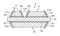
図1に示すように、本発明の実施の形態にかかる絶縁基板1は、AlN 、Al2O3、Si3N4等からなる(板状の)セラミックス基板10の一方の主面(表面)に、(銅やアルミニウム等からなる)放熱側金属板12の一方の主面(表面)がろう材層14を介してろう付けされた絶縁基板1であって、前記セラミックス基板10と前記放熱側金属板12との間から露出するろう材層14(の端部)を覆うNiめっき層21が設けられ、前記放熱側金属板12の他方の主面の少なくとも一部がNiめっき層に覆われておらず、前記放熱側金属板の表面が露出した状態であることを特徴とする。
また、前記放熱側金属板12の側面12aの一部もしくは全部が前記Niめっき層21で覆われていてもよく、前記放熱側金属板12の他方の主面(表面)の周囲が前記Niめっき層21で覆われていてもよい。
また、前記放熱側金属板12の側面12aの一部もしくは全部が前記Niめっき層21で覆われていてもよく、前記放熱側金属板12の他方の主面(表面)の周囲が前記Niめっき層21で覆われていてもよい。
また、前記セラミックス基板10の他方の主面(表面)に、(銅やアルミニウム等からなる)回路側金属板11の一方の主面(表面)がろう材層13を介してろう付けされている。また、前記放熱側金属板12が銅板または銅合金板であることが好ましく、前記回路側金属板11が銅板または銅合金板であることが好ましい。また、前記放熱側金属板12の他方の主面において、Niめっき層に覆われておらず、前記放熱側金属板の主面が露出している領域は、前記放熱側金属板の他方の主面の面積に対して70面積%以上であることが好ましく、80%以上であることがより好ましく、90%以上であることがさらに好ましい。
なお、図1では、セラミックス基板10の他方の主面(上の面)に、回路側金属板11の一方の主面(表面)をろう材層13によってろう付けし、セラミックス基板10の一方の主面(下の面)に、放熱側金属板12の一方の主面(表面)をろう材層14によってろう付けした状態を示している。回路側金属板11は所定の回路の形状にされており、回路側金属板11には、半導体チップなどの電子部品(図示せず)がはんだ付けされる。また、放熱側金属板12には熱伝導性に優れたCuやAlの放熱板(ベース板、図示せず)が放熱側金属板12の他方の面の略全面にはんだ付けされて、パワーモジュールなどが作製される。
かかる絶縁基板1にあっては、パワーモジュールとして使用された場合に、上述の半導体チップを回路側銅板11に半田付けする際や放熱板を放熱側金属板12に半田付けする際、さらには半導体チップの通電時に発熱が繰り返されるなどにより、セラミックス基板10と回路側金属板11および放熱側金属板12との熱膨張率の相違により発生する熱応力、さらにはヒートサイクル負荷により、回路側金属板11、放熱側金属板12の端部において、セラミックス基板10の表面に応力集中が発生してセラミックス基板10にクラックを生ずる恐れがある。そのため、例えばこの実施の形態にかかる絶縁基板1に示すように、回路側金属板11、放熱側金属板12の側面11a、12aをテーパ面に形成することにより、回路側金属板11、放熱側金属板12の端部において、セラミックス基板10に発生する応力集中を緩和させる対策が講じられている。また、例えば銅板の端部に段差を形成することで、ヒートサイクル特性を向上させる技術も知られている。このような熱応力やヒートサイクル負荷に対して絶縁基板1のセラミックス基板10にクラックの発生を防止できるかは、後述の絶縁基板1(単体)の通炉耐性で評価することができる。
しかしながら、上記通炉耐性を満足しても絶縁基板1に不具合が発生することが判明した。すなわち放熱板をはんだ付けした状態(例えば半導体パワーモジュールに組み込まれたた状態)では、放熱側金属板12の端部よりも内側の箇所(接合領域)においてセラミックス基板10にクラックを生ずる場合があることを見出した。本発明者は、この放熱側金属板12の端部よりも内側の箇所においてセラミックス基板10に発生するクラックの要因について検討した。その結果、放熱板を放熱側金属板12にはんだ付けした際に、ろう材層14にはんだが接触すると、はんだを構成する成分(例えばSn)がろう材層に拡散してろう材層を構成するAg、Cuなどの元素と化合物が形成されるといった、ろう材層14のはんだ食われが生じることが判明した。そして、ろう材層14のはんだ食われにより、ろう材層14にCu-Snなどの脆い化合物が形成されることに起因すると考えられるクラックが、ろう材層14の内部に(接合界面に略平行方向に)発生していることが観察された。
さらに絶縁基板1の断面の解析を行ったところ、放熱側金属板12の端部よりも内側のろう材層14中の箇所であって、且つろう材層14中のクラックの先端部においてセラミックス基板10の一方の面(表面)から厚さ方向にクラックが発生していることが観察された。また、シミュレーションにより応力解析を行ったところ、ろう材層14中に前記クラックが存在すると、そのクラックの先端部でセラミックス基板10の表面に応力集中が発生することが確認され、この応力集中によりセラミックス基板10の表面にクラックの発生が起きることが判明した。近年、パワーモジュールの動作温度は上昇する傾向にあり、また、Sn含有量の多い高温はんだの使用が増加しており、前記のろう材食われに起因するセラミックス基板10のクラック発生が増加することが考えられる。本発明では、Niめっきによって、ろう材層14へのはんだの接触を防止することにより、ろう材層14中へのSn等の浸食を回避するようにして、前記ろう材層14中へのクラックの発生およびその先端からのセラミックス基板へのクラックの発生を抑制することに成功した。
さらに前記ろう材層中のクラックを防止することにより、絶縁基板の放熱性の劣化を抑制することができる。
さらに前記ろう材層中のクラックを防止することにより、絶縁基板の放熱性の劣化を抑制することができる。
具体的には図1に示すように、セラミックス基板10と放熱側金属板12との間から露出するろう材層14の端部を覆うように、Niめっき層21が設けられている。この実施の形態にかかる絶縁基板1では、セラミックス基板10と放熱側金属板12との間から露出するろう材層14の端部と放熱側金属板12の側面12aの一部を覆うように、Niめっき層21が設けられている。セラミックス基板10との接合面(一方の面)を除く放熱側金属板12の表面において、Niめっき層21が存在していない残りの部分は放熱側金属板12が露出した状態になっている、すなわち、放熱板側金属板12の他方の面(図1では下面)と、放熱側金属板12の側面12aの一部を除く部分にはNiめっき層21が無く、放熱側金属板12の表面が露出した状態になっている。
言い換えれば、セラミックス基板10と放熱側金属板12との間から露出するろう材層14を覆うNiめっき層21が形成されたNiめっき領域が設けられ、前記放熱側金属板12の他方の主面(の少なくとも周囲を除く領域)は、Niめっきが形成されていない非Niめっき領域である絶縁基板1である。
放熱側金属板12の全面をNiめっきで覆うと通炉耐性が劣化する恐れがあるので、放熱側金属板12の他方の主面はNiめっきで覆わないことが好ましい。
放熱側金属板12の全面をNiめっきで覆うと通炉耐性が劣化する恐れがあるので、放熱側金属板12の他方の主面はNiめっきで覆わないことが好ましい。
なお、Niめっき層21は、ろう材層14からろう材層中の成分(例えばAg)とはんだ構成成分(例えばSn)との相互拡散を防止できる機能を有していれば良く、本発明のNiめっき層は、Niめっき層またはNi合金めっき層を意味し、例えば電気Niめっき層、無電解Ni-Pめっき層、無電解Ni-Bめっき層などのNiまたはNi合金めっきも含まれる。
また、図1に示すように、セラミックス基板10と回路側金属板11との間から露出するろう材層13の端部を覆うように、Niめっき層20を設けてもよい。この実施の形態にかかる絶縁基板1では、セラミックス基板10と回路側金属板11との間から露出するろう材層13(の端部)と回路側金属板11の側面11aの一部を覆うように、Niめっき層20が設けられている。セラミックス基板10との接合面を除く回路側金属板11の表面において、Niめっき層20に覆われていない残りの部分は回路側金属板11の表面が露出した状態になっている、すなわち、回路側金属板11の上面と、側面11aの一部を除く部分にはNiめっき層20が無く、回路側金属板11の表面が露出した状態になっている。
本発明の実施の形態にかかる絶縁基板1において、所定の回路の形状にされた回路側金属板11の他方の面には、半導体チップなどの電子部品(図示せず)がはんだ付け等により搭載される。また、放熱側金属板12の他方の面には熱伝導性に優れたCuやAlの放熱板(ベース板、図示せず)がはんだ付けされる。これにより、半導体パワーモジュールなどが作製される。
図1に示す本発明の実施の形態にかかる絶縁基板1にあっては、セラミックス基板10と回路側金属板11との間から露出しているろう材層13の端部がNiめっき層20で被覆されている。
ただし、回路側のろう材層13はNiめっきで被覆されていなくても良い。なぜなら、パワーモジュールの組み立て工程において回路側金属板11に電子部品をはんだ付けする際に、通常、回路側のろう材層13にはんだが付着する可能性は低いからである。
実施例に後述するように、Niめっきの成膜には無電解めっき(浸漬めっき)を採用することが生産性・コスト面で優れているので好ましい。回路側金属板11の他方の主面(表面)および放熱側金属板12の他方の主面(表面)にNiめっきが被膜されないようにめっきレジストを塗布した後に、無電解Niめっきを施した場合は、各表面がNiめっきで覆われていないことから、通炉耐性および端子の超音波接合性など特性が良好となる。この製法を用いた場合は回路側のろう材層13もNiめっきで被膜される。
本発明の実施の形態にかかる絶縁基板1にあっては、回路側金属板11および放熱側金属板12のいずれも全体がNiめっきで覆われることがないので、通炉耐性が低下するという問題を生じない。Niめっきは銅やアルミニウムなどの回路側金属板11および放熱側金属板12よりも硬度が高く、さらに無電解Ni-Pめっきのようにチップや放熱板の半田付けなどの熱履歴により硬度が高くなることがある。硬度の高いNiめっきは通炉耐性を劣化させるが、本発明によれば、絶縁基板の金属板全体(回路側金属板および放熱側金属板の他方の主面)をNiめっきで被覆した構造ではないため、硬度の高いNiめっきによる通炉耐性の低下という問題は生じない。
また、近年、パワーモジュールの大電流化が進んだことで、前記絶縁基板とパワーモジュールの構成部品である銅端子(バスバー)との接合技術として、従来のはんだ接合やAlワイヤーボンディング接合に代わって、銅バスバーを直接に絶縁基板の回路板の表面に超音波接合する事例が増えている。このような銅バスバーの超音波接合において、回路金属板の表面がNiめっきで覆われている場合、銅バスバーと絶縁基板の(銅)回路板との固相拡散が妨げられ、銅バスバーと絶縁基板との接合強度が低下するという恐れがあった。本発明の実施の形態に関わる構造では、銅バスバーと絶縁基板の回路上面とが接合する表面にNiめっき層が存在しないため、銅バスバーの超音波接合時に銅バスバーの銅と回路の銅との固相拡散が促進され、接合強度の高い端子接合が得られる。
以上により、本発明によれば、パワーモジュール組み立て時の実装性(通炉耐性および超音波接合性)に優れ、かつ、パワーモジュール(放熱板に絶縁基板がはんだ付けされた構造)における高温でのヒートサイクル特性に優れた絶縁基板を提供することができる。
なお、図1では、回路側のろう材層13の端部と回路側金属板11の側面11aの一部を覆うようにNiめっき層20を設け、放熱側のろう材層14の端部と放熱側金属板12の側面12aの一部を覆うように、Niめっき層21が設けた例を示したが、図2に示すように、ろう材層13、14の端部に加えて、回路側金属板11、放熱側金属板12の側面11a、12aの全体をNiめっき層20、21で覆うようにしても良い。また、図3に示すように、回路側金属板11、放熱側金属板12の側面11a、12aに加えて、さらに回路側金属板11の上面の一部(他方の主面の周縁部)と放熱側金属板銅板12の下面の一部(他方の主面の周縁部)までNiめっき層20、21で覆うようにしても良い。
本発明の絶縁基板の製造方法は、セラミックス基板の一方の主面に、放熱側金属板の一方の主面がろう材層を介して接合され、セラミックス基板の他方の主面に、回路側金属板の一方の主面がろう材層を介して接合された絶縁基板において、
前記放熱側金属板の他方の主面(および好ましくは前記回路側金属板の他方の主面)にめっきレジストを形成し、前記レジストが形成された絶縁基板をNiめっき液中に浸漬して、レジストが形成されていない前記セラミックス基板と前記放熱側金属板との間(および好ましくは前記セラミックス基板と前記回路側金属板との間)から露出するろう材層にNiめっき層を形成し、次いで前記レジストを剥離することを特徴とする。
前記放熱側金属板および前記回路側金属板の側面の一部もしくは全部が前記Niめっき層で覆われていてもよく、前記放熱側金属板の他方の主面の周囲が前記Niめっき層で覆われていてもよい。
前記放熱側金属板および前記回路側金属板が、銅板または銅合金板であることが好ましく、前記ろう材層がCu、Ag、Snから選ばれるいずれかひとつの金属成分と、Ti、Hf、Zrから選ばれるいずれかひとつの活性金属成分のを有することが好ましい。
以上、本発明の一実施形態について説明したが、本発明はかかる例に限定されない。当業者であれば、特許請求の範囲に記載された技術的思想の範疇内において、各種の変更例または修正例に想到しうることは明らかであり、それらについても当然に本発明の技術的範囲に属するものと了解される。
(実施例1)
セラミックス基板として46mm×48mm×0.4mmの大きさの市販の窒化アルミニウム基板を準備した。また、83質量%の銀粉と10質量%の銅粉と5質量%の錫粉と(活性金属成分としての)2質量%のチタン粉(Ag:Cu:Sn:Ti=83:10:5:2)をビヒクルに加えて混練して活性金属含有ろう材ペーストを作製し、セラミックス基板の両面の全面に、ろう材ペーストの厚さが10μmになるようにスクリーン印刷した後、大気中で乾燥してろう材層を形成した。次いでろう材層に46mm×48mm×0.3mmの2枚の無酸素銅板をそれぞれ接触配置し、真空炉中で850℃に加熱して窒化アルミニウム基板の両面に銅板を接合して、窒化アルミニウム基板の一方の表面に放熱側銅板形成用の銅板の一方の面が接合(形成)され、窒化アルミニウム基板の他方の主面に回路パターン形成用の銅板の一方の主面が接合(形成)された接合体を得た。
セラミックス基板として46mm×48mm×0.4mmの大きさの市販の窒化アルミニウム基板を準備した。また、83質量%の銀粉と10質量%の銅粉と5質量%の錫粉と(活性金属成分としての)2質量%のチタン粉(Ag:Cu:Sn:Ti=83:10:5:2)をビヒクルに加えて混練して活性金属含有ろう材ペーストを作製し、セラミックス基板の両面の全面に、ろう材ペーストの厚さが10μmになるようにスクリーン印刷した後、大気中で乾燥してろう材層を形成した。次いでろう材層に46mm×48mm×0.3mmの2枚の無酸素銅板をそれぞれ接触配置し、真空炉中で850℃に加熱して窒化アルミニウム基板の両面に銅板を接合して、窒化アルミニウム基板の一方の表面に放熱側銅板形成用の銅板の一方の面が接合(形成)され、窒化アルミニウム基板の他方の主面に回路パターン形成用の銅板の一方の主面が接合(形成)された接合体を得た。
次に、接合体の回路パターン形成用の銅板の他方の主面(セラミックス基板に接合された面の反対側の面)に所定の回路パターン形状の紫外線硬化アルカリ剥離型レジストをスクリーン印刷により塗布し、接合体の放熱側銅板形成用の銅板の他方の主面(セラミックス基板に接合された面の反対側の面)の中央部に、45mm×47mmの長方形の形状の紫外線硬化アルカリ剥離型レジストをスクリーン印刷により塗布し、これらのレジストに紫外線を照射して硬化させた後、塩化銅と塩酸と残部の水とからなるエッチング液により銅板の不要な部分をエッチングし、水酸化ナトリウム水溶液によりレジストを除去して銅板からなる回路パターン(回路側銅板)および放熱側銅板を形成した。
次に、希硫酸に20秒間浸漬して酸洗し、1.6質量%のEDTA・4Naと3質量%のアンモニア水(28質量%のアンモニアを含むアンモニア水)と5質量%の過酸化水素水(35質量%の過酸化水素を含む過酸化水素水)を含むキレート水溶液に20℃で20分間浸漬し、2質量%のエチレントリアミン五酢酸(DTPA)・5Naと5質量%の過酸化水素水を含むキレート水溶液に20℃で52分間浸漬することにより、セラミックス基板表面の銅回路パターンの間や放熱側銅板の周囲に残留する活性金属含有ろう材の不要な部分を除去し絶縁基板の中間製品を得た。
次に、14質量%の硫酸と3.2質量%の過酸化水素と残部の水とからなる化学研磨液に前記中間製品を45℃で5分間浸漬して回路側銅板および放熱側銅板の表面を化学研磨により除去して、活性金属含有ろう材を回路側銅板および放熱側銅板の側面部から0.3mm程度はみ出させ、所定の形状の回路側銅板および放熱側銅板を形成する工程を完了させた。
次に、Niめっきを所定の領域に施すために回路側銅板および放熱側銅板の主面の全面に紫外線硬化アルカリ剥離型レジストをスクリーン印刷により塗布し、レジストに紫外線を照射し硬化することで、各銅板の主面のみをレジスト膜により被覆した。
次に、このレジスト膜付き接合体に無電解Ni-Pめっきを施し、厚さ4μmのめっき被膜を形成したのちに、水酸化ナトリウム水溶液によりレジストを除去して、セラミックス基板と放熱側銅板の間から露出するろう材層、セラミックス基板と回路側銅板の間から露出するろう材層およびそれぞれの銅板の側面がNiめっき層に被覆された金属-セラミックス絶縁基板を得た。なお、回路側金属板および放熱側金属板の他方の主面にNiめっき層は形成されていない。
このようにして作成した金属-セラミックス絶縁基板について、以下のような「ろう材食われ評価」、「通炉耐性評価」、「超音波接合性評価」を実施した。
「ろう材食われ評価」
まず、120mm×60mm×3mmの銅ベース板(放熱板)の表面中央部に、メタルマスクを用いて絶縁基板の外形と同形状(46mm×48mm)にSn-5.0Sbフラックス入りペーストはんだ(千住金属工業株式会社製、エコソルダーM10)をペースト厚さ300μmとなるように塗布した。
まず、120mm×60mm×3mmの銅ベース板(放熱板)の表面中央部に、メタルマスクを用いて絶縁基板の外形と同形状(46mm×48mm)にSn-5.0Sbフラックス入りペーストはんだ(千住金属工業株式会社製、エコソルダーM10)をペースト厚さ300μmとなるように塗布した。
次に、このペーストはんだの上に前述の金属-セラミックス絶縁基板を搭載し、N2雰囲気下で270℃まで昇温した後、270℃を保持したまま真空排気を3分間実施した後に降温することで、金属-セラミックス絶縁基板を銅ベース板(放熱板)にはんだ付けした。はんだ付け後のはんだ厚は約200μmだった。
このようにして得たベース板付き絶縁基板について、断面観察試料を作製しエネルギ-分散型X線分析装置を備えた走査型電子顕微鏡(SEM/EDS)による元素マッピングを実施し、ろう材食われの発生有無を確認した。その結果、本実施例1で作成した金属-セラミックス絶縁基板では、ろう材層を被覆するNi-Pめっきにより絶縁基板のろう材層にはんだの成分であるSn等がろう材層側へ拡散しておらず、脆いCu-Sn化合物が生成していない(ろう材食われが起きていない)ことがSEM/EDSによる元素マッピングから確かめられた。
「通炉耐性評価」
次に通炉耐性を評価するために、本実施例の金属-セラミックス絶縁基板(ベース板を半田付けしていない)4個に対して通炉3回(還元雰囲気(水素/窒素=20/80)下において350℃で10分間加熱した後に室温まで冷却する処理を3回繰り返す)の熱負荷を与えた。通炉3回後のセラミックス部のクラック発生有無を光学顕微鏡により基板全域にわたり検査した。本実施例の金属-セラミックス絶縁基板は、通炉3回後のクラック発生は無く、高い通炉耐性を持つことが確かめられた。
次に通炉耐性を評価するために、本実施例の金属-セラミックス絶縁基板(ベース板を半田付けしていない)4個に対して通炉3回(還元雰囲気(水素/窒素=20/80)下において350℃で10分間加熱した後に室温まで冷却する処理を3回繰り返す)の熱負荷を与えた。通炉3回後のセラミックス部のクラック発生有無を光学顕微鏡により基板全域にわたり検査した。本実施例の金属-セラミックス絶縁基板は、通炉3回後のクラック発生は無く、高い通炉耐性を持つことが確かめられた。
「超音波接合性評価」
次に超音波接合性を評価するために、銅端子(超音波接合面のサイズ5mm×5mm、厚み1mm)を超音波接合装置で本実施例の金属-セラミックス絶縁基板に超音波接合したのち、超音波探傷像により超音波接合部の接合面積率を評価し、シェア強度測定器によりシェア強度を評価した。本実施例の金属-セラミックス絶縁の接合面積率は70%以上、シェア強度は1500N以上であり、良好な超音波接合性を示した。また、超音波接合部の断面にSEM/EDS観察を実施したところ、銅端子部と絶縁基板の銅回路部とが一体化していることも確認できた。
次に超音波接合性を評価するために、銅端子(超音波接合面のサイズ5mm×5mm、厚み1mm)を超音波接合装置で本実施例の金属-セラミックス絶縁基板に超音波接合したのち、超音波探傷像により超音波接合部の接合面積率を評価し、シェア強度測定器によりシェア強度を評価した。本実施例の金属-セラミックス絶縁の接合面積率は70%以上、シェア強度は1500N以上であり、良好な超音波接合性を示した。また、超音波接合部の断面にSEM/EDS観察を実施したところ、銅端子部と絶縁基板の銅回路部とが一体化していることも確認できた。
(比較例1)
図4に示すように、回路側銅板および放熱側銅板を形成後の(部分Niめっき用の)レジスト印刷工程および無電解Ni-Pめっき工程を実施せず、いっさいのNiめっき層が存在しないこと以外は、実施例1と同様の方法により、比較例1の金属-セラミックス絶縁基板を得た。
図4に示すように、回路側銅板および放熱側銅板を形成後の(部分Niめっき用の)レジスト印刷工程および無電解Ni-Pめっき工程を実施せず、いっさいのNiめっき層が存在しないこと以外は、実施例1と同様の方法により、比較例1の金属-セラミックス絶縁基板を得た。
この金属-セラミックス絶縁基板について実施例1と同様の方法により、「ろう材食われ評価」、「通炉耐性評価」、「超音波接合性評価」を実施した。
「ろう材食われ評価」
本比較例1で作成した金属-セラミックス絶縁基板では、ベース付けに用いたはんだは放熱側の銅板の側面に濡れ広がり、セラミックス基板と放熱側銅板の間から露出したろう材層とはんだとが接触し、絶縁基板のろう材層にはんだの成分であるSn等がろう材層側へ拡散し、ろう材層に脆いCu-Sn化合物が生成している(ろう材食われが起きている)ことがSEM/EDSによる元素マッピングから確かめられた。
本比較例1で作成した金属-セラミックス絶縁基板では、ベース付けに用いたはんだは放熱側の銅板の側面に濡れ広がり、セラミックス基板と放熱側銅板の間から露出したろう材層とはんだとが接触し、絶縁基板のろう材層にはんだの成分であるSn等がろう材層側へ拡散し、ろう材層に脆いCu-Sn化合物が生成している(ろう材食われが起きている)ことがSEM/EDSによる元素マッピングから確かめられた。
「通炉耐性評価」
本比較例1の金属-セラミックス絶縁基板は、通炉3回後のクラック発生は無く、高い通炉耐性を持つことが確かめられた。
本比較例1の金属-セラミックス絶縁基板は、通炉3回後のクラック発生は無く、高い通炉耐性を持つことが確かめられた。
「超音波接合性評価」
本比較例1の金属-セラミックス絶縁基板は、超音波接合部の接合面積率が70%以上であり、シェア強度は1500N以上であり、良好な超音波接合性を示した。また、超音波接合部の断面をSEM/EDSで観察したところ、銅端子部と絶縁基板の銅回路部とが一体化していることも確認できた。
本比較例1の金属-セラミックス絶縁基板は、超音波接合部の接合面積率が70%以上であり、シェア強度は1500N以上であり、良好な超音波接合性を示した。また、超音波接合部の断面をSEM/EDSで観察したところ、銅端子部と絶縁基板の銅回路部とが一体化していることも確認できた。
(比較例2)
図5に示すように、回路側銅板および放熱側銅板を形成後の(部分Niめっき用の)レジスト印刷工程を実施せず、絶縁基板の回路側銅板および放熱側銅板の表面が厚さ4μmのNi-Pめっき層によって被覆されていること以外は、実施例1と同様の方法により、比較例2の金属-セラミックス絶縁基板を得た。
図5に示すように、回路側銅板および放熱側銅板を形成後の(部分Niめっき用の)レジスト印刷工程を実施せず、絶縁基板の回路側銅板および放熱側銅板の表面が厚さ4μmのNi-Pめっき層によって被覆されていること以外は、実施例1と同様の方法により、比較例2の金属-セラミックス絶縁基板を得た。
この金属-セラミックス絶縁基板について実施例1と同様の方法により、「ろう材食われ評価」、「通炉耐性評価」、「超音波接合性評価」を実施した。
「ろう材食われ評価」
本比較例2で作成した金属-セラミックス絶縁基板では、ろう材層を被覆するNi-Pめっきにより絶縁基板のろう材層にはんだの成分であるSn等がろう材層側へ拡散しておらず、脆いCu-Sn化合物が生成していない(ろう材食われが起きていない)ことがSEM/EDSによる元素マッピングから確かめられた。
本比較例2で作成した金属-セラミックス絶縁基板では、ろう材層を被覆するNi-Pめっきにより絶縁基板のろう材層にはんだの成分であるSn等がろう材層側へ拡散しておらず、脆いCu-Sn化合物が生成していない(ろう材食われが起きていない)ことがSEM/EDSによる元素マッピングから確かめられた。
「通炉耐性評価」
本比較例2の金属-セラミックス絶縁基板は、通炉3回後にセラミックス部にクラック(4個中2個)が発生しており、通炉耐性が低かった。
本比較例2の金属-セラミックス絶縁基板は、通炉3回後にセラミックス部にクラック(4個中2個)が発生しており、通炉耐性が低かった。
「超音波接合性」
本比較例の金属-セラミックス絶縁基板は、緒音波接合部の接合面積率が50%であり、シェア強度は600Nと低く、超音波接合性が不良であった。また、超音波接合部の断面にSEM/EDS観察を実施したところ、銅端子部と絶縁基板の銅回路部との間にNi-Pめっき被膜が残存している箇所があり、銅端子と銅回路部が一体化していなかった。
本比較例の金属-セラミックス絶縁基板は、緒音波接合部の接合面積率が50%であり、シェア強度は600Nと低く、超音波接合性が不良であった。また、超音波接合部の断面にSEM/EDS観察を実施したところ、銅端子部と絶縁基板の銅回路部との間にNi-Pめっき被膜が残存している箇所があり、銅端子と銅回路部が一体化していなかった。
実施例1および比較例1、2の結果を表1にまとめて示す。

絶縁基板の回路側金属板(回路側銅板)および放熱側金属板(放熱側銅板)の表面の全面にNiめっき層を形成した場合、Niめっき層がろう材層のAgとはんだ由来のSnの相互拡散を防止するため、前記のろう材食われは起こらない。しかしながら、絶縁基板の回路側金属板(回路側銅板)および放熱側金属板(放熱側銅板)の表面の全面にNiめっき層を形成した場合、硬度の硬いNiめっき層が存在することで、パワーモジュール組み立て時に受ける熱負荷に対する信頼性(通炉耐性)が低下するという課題がある。また、絶縁基板の回路金属板(回路側銅板)の表面に銅ターミナル端子を超音波接合するという用途もあり、この場合、銅ターミナル端子が接合される表面はNiめっきされていない銅であることが好ましい。
本発明は、例えば半導体パワーモジュールなどに利用される絶縁基板に利用することができる。
1 絶縁基板
10 セラミックス基板
11 回路側金属板(回路側銅板)
12 放熱側金属板(放熱側銅板)
13、14 ろう材層
11a、12a 側面
20、21 Niめっき層
10 セラミックス基板
11 回路側金属板(回路側銅板)
12 放熱側金属板(放熱側銅板)
13、14 ろう材層
11a、12a 側面
20、21 Niめっき層
Claims (13)
- セラミックス基板の一方の主面に、放熱側金属板の一方の主面がろう材層を介してろう付けされた絶縁基板であって、
前記セラミックス基板と前記放熱側金属板との間から露出するろう材層を覆うNiめっき層が設けられ、
前記放熱側金属板の他方の主面の少なくとも一部がNiめっき層に覆われておらず、前記放熱側金属板の表面が露出した状態であることを特徴とする、絶縁基板。 - 前記放熱側金属板の側面の一部もしくは全部が前記Niめっき層で覆われていることを特徴とする、請求項1に記載の絶縁基板。
- 前記放熱側金属板の他方の主面の周囲が前記Niめっき層で覆われていることを特徴とする、請求項1または2に記載の絶縁基板。
- 前記セラミックス基板の他方の主面に、回路側金属板の一方の主面がろう材層を介してろう付けされていることを特徴とする、請求項1~3のいずれかに記載の絶縁基板。
- 前記回路側金属板が銅板または銅合金板であることを特徴とする、請求項4に記載の絶縁基板。
- 前記放熱側金属板が銅板または銅合金板であることを特徴とする、請求項1~5のいずれかに記載の絶縁基板。
- セラミックス基板の一方の主面に、放熱側金属板の一方の主面がろう材層を介して接合され、セラミックス基板の他方の主面に、回路側金属板の一方の主面がろう材層を介して接合された絶縁基板において、
前記放熱側金属板の他方の主面にめっきレジストを形成し、
前記めっきレジストが形成された絶縁基板をNiめっき液中に浸漬して、前記めっきレジストが形成されていない前記セラミックス基板と前記放熱側金属板との間から露出するろう材層にNiめっき層を形成し、次いで前記めっきレジストを剥離することを特徴とする、絶縁基板の製造方法。 - 前記放熱側金属板の側面の一部もしくは全部が前記Niめっき層で覆われていることを特徴とする、請求項7に記載の絶縁基板の製造方法。
- 前記放熱側金属板の他方の主面の周囲が前記Niめっき層で覆われていることを特徴とする、請求項7または8に記載の絶縁基板の製造方法。
- 前記回路側金属板の他方の主面にめっきレジストを形成し、前記セラミックス基板と前記回路側金属板との間から露出するろう材層にNiめっき層を形成することを特徴とする、請求項7~9のいずれかに記載の絶縁基板の製造方法。
- 前記回路側金属板の側面の一部もしくは全部が前記Niめっき層で覆われていることを特徴とする、請求項7~10のいずれかに記載の絶縁基板の製造方法。
- 前記放熱側金属板および前記回路側金属板が、銅板または銅合金板であることを特徴とする、請求項7~11のいずれかに記載の絶縁基板の製造方法。
- 前記ろう材層がCu、Ag、Snから選ばれるいずれかひとつの金属成分と、Ti、Hf、Zrから選ばれるいずれかひとつの活性金属成分を有することを特徴とする、請求項7~12のいずれかに記載の絶縁基板の製造方法。
Priority Applications (4)
| Application Number | Priority Date | Filing Date | Title |
|---|---|---|---|
| EP21842920.7A EP4184562A1 (en) | 2020-07-15 | 2021-06-29 | Insulation substrate and method for manufacturing same |
| US18/010,104 US20230268245A1 (en) | 2020-07-15 | 2021-06-29 | Insulating substrate and manufacturing method thereof |
| CN202180049035.2A CN115812342A (zh) | 2020-07-15 | 2021-06-29 | 绝缘基板及其制造方法 |
| KR1020237001568A KR20230039649A (ko) | 2020-07-15 | 2021-06-29 | 절연 기판 및 그 제조 방법 |
Applications Claiming Priority (2)
| Application Number | Priority Date | Filing Date | Title |
|---|---|---|---|
| JP2020-121493 | 2020-07-15 | ||
| JP2020121493A JP2022024310A (ja) | 2020-07-15 | 2020-07-15 | 絶縁基板およびその製造方法 |
Publications (1)
| Publication Number | Publication Date |
|---|---|
| WO2022014319A1 true WO2022014319A1 (ja) | 2022-01-20 |
Family
ID=79555435
Family Applications (1)
| Application Number | Title | Priority Date | Filing Date |
|---|---|---|---|
| PCT/JP2021/024584 WO2022014319A1 (ja) | 2020-07-15 | 2021-06-29 | 絶縁基板およびその製造方法 |
Country Status (6)
| Country | Link |
|---|---|
| US (1) | US20230268245A1 (ja) |
| EP (1) | EP4184562A1 (ja) |
| JP (1) | JP2022024310A (ja) |
| KR (1) | KR20230039649A (ja) |
| CN (1) | CN115812342A (ja) |
| WO (1) | WO2022014319A1 (ja) |
Citations (8)
| Publication number | Priority date | Publication date | Assignee | Title |
|---|---|---|---|---|
| JP2001024296A (ja) | 1999-07-07 | 2001-01-26 | Kyocera Corp | セラミック回路基板 |
| JP2002009212A (ja) * | 2000-06-23 | 2002-01-11 | Denki Kagaku Kogyo Kk | 放熱構造体の製造方法 |
| JP2006228918A (ja) * | 2005-02-17 | 2006-08-31 | Hitachi Metals Ltd | セラミックス回路基板およびそれを用いた半導体モジュール |
| JP2009070863A (ja) | 2007-09-11 | 2009-04-02 | Hitachi Ltd | 半導体パワーモジュール |
| JP2010241627A (ja) | 2009-04-03 | 2010-10-28 | Dowa Metaltech Kk | 金属−セラミックス接合基板およびそれに用いるろう材 |
| JP2011097049A (ja) * | 2009-10-01 | 2011-05-12 | Hitachi Metals Ltd | 窒化珪素回路基板およびその製造方法 |
| JP2011181634A (ja) * | 2010-02-26 | 2011-09-15 | Nisshin Steel Co Ltd | 半導体発熱部品搭載用放熱構造体の製造法 |
| JP2016076603A (ja) * | 2014-10-07 | 2016-05-12 | Dowaメタルテック株式会社 | 金属−セラミックス回路基板およびその製造方法 |
-
2020
- 2020-07-15 JP JP2020121493A patent/JP2022024310A/ja active Pending
-
2021
- 2021-06-29 KR KR1020237001568A patent/KR20230039649A/ko unknown
- 2021-06-29 CN CN202180049035.2A patent/CN115812342A/zh active Pending
- 2021-06-29 WO PCT/JP2021/024584 patent/WO2022014319A1/ja unknown
- 2021-06-29 EP EP21842920.7A patent/EP4184562A1/en active Pending
- 2021-06-29 US US18/010,104 patent/US20230268245A1/en active Pending
Patent Citations (8)
| Publication number | Priority date | Publication date | Assignee | Title |
|---|---|---|---|---|
| JP2001024296A (ja) | 1999-07-07 | 2001-01-26 | Kyocera Corp | セラミック回路基板 |
| JP2002009212A (ja) * | 2000-06-23 | 2002-01-11 | Denki Kagaku Kogyo Kk | 放熱構造体の製造方法 |
| JP2006228918A (ja) * | 2005-02-17 | 2006-08-31 | Hitachi Metals Ltd | セラミックス回路基板およびそれを用いた半導体モジュール |
| JP2009070863A (ja) | 2007-09-11 | 2009-04-02 | Hitachi Ltd | 半導体パワーモジュール |
| JP2010241627A (ja) | 2009-04-03 | 2010-10-28 | Dowa Metaltech Kk | 金属−セラミックス接合基板およびそれに用いるろう材 |
| JP2011097049A (ja) * | 2009-10-01 | 2011-05-12 | Hitachi Metals Ltd | 窒化珪素回路基板およびその製造方法 |
| JP2011181634A (ja) * | 2010-02-26 | 2011-09-15 | Nisshin Steel Co Ltd | 半導体発熱部品搭載用放熱構造体の製造法 |
| JP2016076603A (ja) * | 2014-10-07 | 2016-05-12 | Dowaメタルテック株式会社 | 金属−セラミックス回路基板およびその製造方法 |
Also Published As
| Publication number | Publication date |
|---|---|
| EP4184562A1 (en) | 2023-05-24 |
| CN115812342A (zh) | 2023-03-17 |
| US20230268245A1 (en) | 2023-08-24 |
| KR20230039649A (ko) | 2023-03-21 |
| JP2022024310A (ja) | 2022-02-09 |
Similar Documents
| Publication | Publication Date | Title |
|---|---|---|
| JP2006240955A (ja) | セラミック基板、セラミック回路基板及びそれを用いた電力制御部品。 | |
| EP2980843B1 (en) | Power module | |
| WO2015114987A1 (ja) | パワーモジュール用基板とその製造方法とそのパワーモジュール用基板を用いたパワーモジュール | |
| JP2000323618A (ja) | 銅回路接合基板及びその製造方法 | |
| JP2002043482A (ja) | 電子回路用部材及びその製造方法並びに電子部品 | |
| JP4360847B2 (ja) | セラミック回路基板、放熱モジュール、および半導体装置 | |
| US10798824B2 (en) | Method for manufacturing insulated circuit board, insulated circuit board, and thermoelectric conversion module | |
| JP2007134563A (ja) | 段差回路基板、その製造方法およびそれを用いた電力制御部品。 | |
| WO2022014319A1 (ja) | 絶縁基板およびその製造方法 | |
| JP2013191640A (ja) | パワーモジュール用基板及びその製造方法 | |
| JP2005347767A (ja) | セラミックス回路基板の製造方法 | |
| JP4018264B2 (ja) | アルミニウム−窒化アルミニウム絶縁基板の製造方法 | |
| JP4756169B2 (ja) | セラミックス回路基板及びその製造方法 | |
| WO2020218193A1 (ja) | セラミックス回路基板および電子部品モジュール | |
| TWI231019B (en) | Lead frame and manufacturing method thereof and a semiconductor device | |
| WO2022014318A1 (ja) | 絶縁基板およびその製造方法 | |
| JP7298988B2 (ja) | セラミックス回路基板及びその製造方法 | |
| JP3199028B2 (ja) | 半導体装置及びその製造方法 | |
| JP2000086368A (ja) | 窒化物セラミックス基板 | |
| JP2001135902A (ja) | セラミックス回路基板 | |
| JP2004080060A (ja) | 電子部品用パッケージ及びその製造方法 | |
| JPS628532A (ja) | 金メツキされた電子部品パツケ−ジ | |
| JP3526711B2 (ja) | 窒化アルミニウム回路基板 | |
| JP2000332183A (ja) | 放熱板付きリードフレーム部材と半導体装置 | |
| JP2000349098A (ja) | セラミック基板と半導体素子の接合体及びその製造方法 |
Legal Events
| Date | Code | Title | Description |
|---|---|---|---|
| 121 | Ep: the epo has been informed by wipo that ep was designated in this application |
Ref document number: 21842920 Country of ref document: EP Kind code of ref document: A1 |
|
| NENP | Non-entry into the national phase |
Ref country code: DE |
|
| ENP | Entry into the national phase |
Ref document number: 2021842920 Country of ref document: EP Effective date: 20230215 |