WO2022014282A1 - ガスセンサ - Google Patents
ガスセンサ Download PDFInfo
- Publication number
- WO2022014282A1 WO2022014282A1 PCT/JP2021/023700 JP2021023700W WO2022014282A1 WO 2022014282 A1 WO2022014282 A1 WO 2022014282A1 JP 2021023700 W JP2021023700 W JP 2021023700W WO 2022014282 A1 WO2022014282 A1 WO 2022014282A1
- Authority
- WO
- WIPO (PCT)
- Prior art keywords
- housing
- end side
- annular groove
- sensor
- base end
- Prior art date
- Legal status (The legal status is an assumption and is not a legal conclusion. Google has not performed a legal analysis and makes no representation as to the accuracy of the status listed.)
- Ceased
Links
Images



Classifications
-
- G—PHYSICS
- G01—MEASURING; TESTING
- G01N—INVESTIGATING OR ANALYSING MATERIALS BY DETERMINING THEIR CHEMICAL OR PHYSICAL PROPERTIES
- G01N27/00—Investigating or analysing materials by the use of electric, electrochemical, or magnetic means
- G01N27/26—Investigating or analysing materials by the use of electric, electrochemical, or magnetic means by investigating electrochemical variables; by using electrolysis or electrophoresis
- G01N27/403—Cells and electrode assemblies
- G01N27/406—Cells and probes with solid electrolytes
- G01N27/407—Cells and probes with solid electrolytes for investigating or analysing gases
- G01N27/4078—Means for sealing the sensor element in a housing
-
- G—PHYSICS
- G01—MEASURING; TESTING
- G01M—TESTING STATIC OR DYNAMIC BALANCE OF MACHINES OR STRUCTURES; TESTING OF STRUCTURES OR APPARATUS, NOT OTHERWISE PROVIDED FOR
- G01M15/00—Testing of engines
- G01M15/04—Testing internal-combustion engines
- G01M15/10—Testing internal-combustion engines by monitoring exhaust gases or combustion flame
- G01M15/102—Testing internal-combustion engines by monitoring exhaust gases or combustion flame by monitoring exhaust gases
Definitions
- This disclosure relates to gas sensors.
- gas sensors have been developed that are arranged in the exhaust system of an internal combustion engine and detect the concentration of a specific gas in the gas to be measured such as exhaust gas.
- a gas sensor in which the sensor body is held inside the housing, it may be required to airtightly seal the gap between the housing and the sensor body.
- the above-mentioned gap is filled with a sealing material to achieve airtight sealing.
- the airtightness is improved in a high thermal environment by specifying the material composition of the housing and the like.
- the present disclosure is intended to provide a gas sensor capable of improving the airtightness between the housing and the sensor body.
- One aspect of the present disclosure is a housing provided with a locking step formed on an inner peripheral surface.
- a sensor body that is provided with a locked collar that is locked from the base end side to the locking step and is held inside the housing.
- the sealing material filled in the filling portion between the inner peripheral surface of the housing and the outer peripheral surface of the sensor body,
- an insulating member arranged between the inner peripheral surface of the housing and the outer peripheral surface of the sensor body is provided.
- the filling portion is in a gas sensor having an annular groove portion protruding on the outer peripheral side.
- the filling portion has the annular groove portion. This makes it possible to improve the airtightness between the housing and the sensor body.
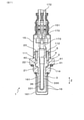
- FIG. 1 is a cross-sectional view taken along the axial direction of the gas sensor in the first embodiment.
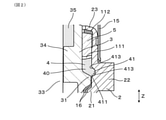
- FIG. 2 is a cross-sectional view of the vicinity of the filling portion in the first embodiment.
- FIG. 3 is a cross-sectional view taken along the line III-III of FIG.
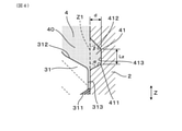
- FIG. 4 is a cross-sectional view of the annular groove portion in the first embodiment.
- FIG. 5 is a cross-sectional view of the vicinity of the filling portion in the comparative form.
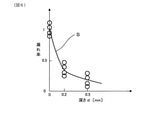
- FIG. 6 is a diagram showing the measurement results in the experimental example.
- FIG. 7 is a cross-sectional view taken along the axial direction of the gas sensor in the second embodiment.
- the gas sensor 1 has a housing 2, a sensor main body 3, a sealing material 4, and an insulating member 5.
- the housing 2 includes a locking step 21 formed on the inner peripheral surface.
- the sensor main body 3 includes a locked flange portion 31 that is locked to the locking step portion 21 from the base end side, and is held inside the housing 2.
- the sealing material 4 is filled in the filling portion 40 between the inner peripheral surface of the housing 2 and the outer peripheral surface of the sensor main body 3 on the base end side of the locked flange portion 31.
- the insulating member 5 is arranged between the inner peripheral surface of the housing 2 and the outer peripheral surface of the sensor main body 3 on the base end side of the sealing material 4.
- the filling portion 40 has an annular groove portion 41 protruding toward the outer peripheral side.
- the sensor main body 3 has a sensor element 33 provided with a sensing unit and an insulating insulator 34 holding the sensor element 33.
- the sensor element 33 is a laminated type sensor element in which a plurality of ceramic layers including a solid electrolyte are laminated.
- the insulating insulator 34 holds the sensor element 33 by inserting it in the axial direction.
- a glass sealing portion 35 is filled in the recess provided at the base end portion of the insulating insulator 34. The glass sealing portion 35 seals between the insulating insulator 34 and the sensor element 33.
- the insulating insulator 34 is made of, for example, a ceramic such as alumina.
- a locked flange portion 31 is formed on the outer peripheral portion of the insulating insulator 34. That is, in this embodiment, the locked flange portion 31 provided on the insulating insulator 34 is locked to the locking step portion 21 of the housing 2.
- a tip end side cover 16 formed so as to cover the sensor main body 3 is provided on the tip end side of the housing 2.
- the gas sensor 1 of this embodiment has a front end side cover 16 having a double structure. These front end side covers 16 are fixed to the housing 2 at the base end portion thereof. In the present embodiment, the base end portion of the front end side cover 16 is interposed between the locking step portion 21 of the housing 2 and the locked flange portion 31 of the sensor main body 3.
- the sealing material 4, the packing 111, the insulating member 5, and the metal ring 112 are sequentially arranged on the base end side of the locked flange portion 31. Further, these members are crimped in the axial direction Z by the caulking portion 23 and receive a compressive load in the axial direction Z.
- the sealing material 4 is made of a ceramic powder such as talc.
- the axial direction Z is the axial direction of the gas sensor 1.
- the tip side cover 16 is formed with a gas flow hole 161 through which the gas to be measured is circulated.
- a gas to be measured such as exhaust gas is introduced into the inside of the front end side cover 16 through the gas flow hole 161 and reaches the measurement electrode (not shown) of the sensor element 33.
- a substantially cylindrical base end side cover 15 is fixed to the base end side of the housing 2.
- the base end side cover 15 is fixed to the outer peripheral surface of the housing 2 by welding or the like on the outer peripheral side of the crimped portion 23.
- a contact terminal 171 for connecting to a terminal provided at the base end portion of the sensor element 33 is arranged inside the base end side cover 15.
- the lead 172 connected to the contact terminal 171 projects toward the proximal end side of the gas sensor 1. Further, the contact terminal 171 is held by the insulating terminal holder 113.
- the terminal holder 113 is made of a ceramic such as alumina, similarly to the insulating insulator 34.
- the base end side cover 15 is provided with an atmosphere introduction unit 151 that introduces the atmosphere inside.
- the atmosphere introduced from the atmosphere introduction unit 151 into the base end side cover 15 reaches a reference electrode (not shown) provided inside the sensor element 33.
- the gas sensor 1 can be installed in the exhaust pipe of the internal combustion engine of a vehicle, for example, to detect the gas of the exhaust gas flowing in the exhaust pipe.
- the gas sensor 1 of this embodiment can be used as an A / F sensor (also referred to as an air-fuel ratio sensor) for detecting an A / F (that is, an air-fuel ratio) of an internal combustion engine obtained from the composition of exhaust gas.
- the sealing material 4 is applied to the filling portion 40. It is filled.
- the gas sensor 1 can also be an oxygen sensor that ON-OFF determines whether the A / F obtained from the composition of the exhaust gas is on the fuel rich side or the fuel lean side with respect to the stoichiometric air-fuel ratio. ..
- the gas sensor 1 is attached to an attached portion such as an exhaust pipe at the attachment screw portion 24 provided in the housing 2. That is, the gas sensor 1 is attached to the attached portion by screwing the attachment screw portion 24 of the housing 2 into the female screw portion provided in the attached portion.
- the housing 2 has the following polygonal portion 22 on the base end side of the mounting screw portion 24. When fastening the mounting screw portion 24 to the mounted portion, the tool is engaged with the polygonal portion 22.
- the polygonal portion 22 protrudes toward the outer peripheral side from the portions on both sides in the axial direction Z, and the outer shape seen from the axial direction Z is polygonal.
- the annular groove portion 41 is provided in the forming region of the polygonal portion 22 in the axial direction Z.
- the polygonal portion 22 has a regular hexagonal shape when viewed from the axial direction.
- the locking step portion 21, the locked flange portion 31, the filling portion 40, and the annular groove portion 41 are formed in a circular shape centered on the central axis of the gas sensor 1.
- the annular groove portion 41 is inclined so that the tip side wall surface 411 is inclined toward the proximal end side toward the outer peripheral side. That is, the angle ⁇ shown in FIG. 4 is less than 90 °. More preferably, the angle ⁇ is 85 ° or less.
- the broken line Z1 in the figure is a straight line parallel to the axial direction Z.
- the angle ⁇ can be, for example, 60 ° or more.
- annular groove portion 41 is inclined so that the base end side wall surface 412 is inclined toward the tip side toward the outer peripheral side.
- the angle ⁇ formed by the proximal side wall surface 412 with the axial direction Z is 45 ° or less.
- the angle ⁇ can be, for example, 15 ° or more.
- the annular groove portion 41 has a depth d of 0.2 to 0.5 mm.
- the annular groove portion 41 has a groove bottom surface 413 on the outer peripheral side along the axial direction Z.
- the length Lz of the groove bottom surface 413 in the axial direction Z can be made longer than the depth d of the annular groove portion 41.
- the length Lz can be, for example, 0.7 mm or more.
- the locked flange portion 31 of the sensor body 3 is inclined so that the front end side surface 311 is inclined toward the base end side toward the outer peripheral side.
- the locked flange portion 31 is inclined so that the base end side surface 312 is inclined toward the tip side toward the outer peripheral side.
- the protruding end of the locked flange portion 31 has a flange top surface 313 along the axial direction Z.
- the difference in position in the axial direction Z between the outer peripheral end of the base end side surface 312 of the locked flange portion 31 and the inner peripheral end of the tip side wall surface 411 of the annular groove portion 41 is 0.3 mm or less.
- the outer peripheral end of the base end side surface 312 and the inner peripheral end of the tip side wall surface 411 are substantially the same in the axial direction Z.
- the crimped portion 23 of the housing 2 is in a state of being erected along the axial direction Z.
- the sensor body 3 is inserted into the housing 2 in this state from the base end side in the axial direction Z.
- the sensor main body 3 is prepared in advance as a sub-assy having a sensor element 33, an insulating insulator 34, and a glass sealing portion 35. Further, in the case of this embodiment, the front end side cover 16 is attached to the housing 2 in advance.
- the sensor main body 3 inserted and arranged in the housing 2 locks the locked flange portion 31 to the locking step portion 21 of the housing 2 via the base end portion of the front end side cover 16.
- the sealing material 4, the packing 111, the insulating member 5, and the metal ring 112 are arranged in this order in the annular space between the outer peripheral surface of the sensor main body 3 and the inner peripheral surface of the housing 2 from the base end side.
- the sealing material 4 is made of ceramic powder such as talc.
- the sealing material 4 is filled in the filling portion 40 including the annular groove portion 41. At this time, the sealing material 4 is pressed in the axial direction Z so that the sealing material 4 is filled as evenly as possible over the entire filling portion 40.
- the caulked portion 23 is formed as shown in FIG.
- the caulking portion 23 crimps and fixes the sealing material 4, the packing 111, the insulating member 5, and the metal ring 112 in the axial direction Z.
- This caulking fixing can be performed by heat caulking, and the base end portion of the housing 2 serving as the caulking portion 23 can be heated to a high temperature to facilitate its deformation.
- the filling portion 40 has an annular groove portion 41. This makes it possible to increase the length of the interface between the sealing material 4 and the housing 2. As a result, the airtightness between the housing 2 and the sensor main body 3 can be improved.
- annular groove portion 41 it is possible to increase the area of the filling portion 40 that receives the surface pressure of the sealing material 4 from the tip side in the axial direction. Therefore, the pressure applied to the sealing material 4 can be increased without increasing the load applied to the locked flange portion 31 of the sensor main body 3. As a result, the airtightness between the housing 2 and the sensor main body 3 can be improved.
- the annular groove portion 41 in the filling portion 40 the amount of the sealing material 4 that can be filled in the filling portion 40 can be increased. As a result, it is easy to suppress a decrease in the internal pressure of the sealing material 4 due to the difference in thermal expansion between the housing 2 and the sensor main body 3. Also from this point of view, the airtightness between the housing 2 and the sensor main body 3 can be improved.
- Some A / F sensors have an atmospheric duct that introduces the atmosphere into the sensor element 33.
- the A / F that is, the air-fuel ratio
- the unburned gas chemically reacts at the electrode exposed to the exhaust gas, and the atmosphere is passed through the solid electrolyte.
- Oxide ions (O2- ) move from the electrode exposed to the exhaust gas to the electrode exposed to the exhaust gas.
- the A / F on the fuel-rich side is detected.
- the sealing property between the space inside the base end side cover 15 and the space inside the front end side cover 16 by the sealing material 4 is important. Further, in the present embodiment, as described above, since the sealing property of the sealing material 4 can be improved, it can be said that it is easy to secure the detection range on the fuel-rich side in the A / F sensor.
- the oxygen sensor detects the rich and lean of the fuel by the output of the electromotive force generated by the difference between the oxygen concentration in the atmosphere in the base end side cover 15 and the oxygen concentration in the exhaust gas in the tip end side cover 16. Therefore, when the gas sensor 1 is an oxygen sensor, if exhaust gas is mixed into the atmosphere side, the detection accuracy may be affected. Therefore, even when the gas sensor 1 of the present embodiment capable of improving the sealing property of the sealing material 4 is applied to the oxygen sensor, there is an advantage in terms of improving the detection accuracy.
- the contact terminal 171 is arranged in the base end side cover 15. Therefore, if the exhaust gas is mixed in the base end side cover 15, the exhaust gas may reach the contact terminal 171. In this case, the contact terminal 171 may be corroded by moisture, nitrogen compounds, etc. in the exhaust gas. Therefore, from the viewpoint of protecting the contact terminal 171 from corrosion, the gas sensor 1 of the present embodiment capable of improving the sealing property of the sealing material 4 is excellent. Further, according to this embodiment, the leakage of the exhaust gas to the base end side in a high temperature environment can be reduced, so that the corrosion resistance reliability of the contact terminal 171 in a higher temperature environment can be ensured.
- annular groove portion 41 is provided in the forming region of the polygonal portion 22 in the axial direction Z. As a result, the annular groove portion 41 can be provided while sufficiently ensuring the strength of the housing 2.
- the annular groove portion 41 is inclined so that the tip side wall surface 411 is directed toward the proximal end side toward the outer peripheral side. As a result, it is easy to fill the annular groove portion 41 with the sealing material 4. Therefore, the sealing material 4 can be filled in the filling portion 40 including the annular groove portion 41 without increasing the filling load when filling the sealing material 4. As a result, the sealing material 4 can be filled in the filling portion 40 without applying an excessive load to the locked flange portion 31 of the sensor main body 3.
- the annular groove portion 41 is inclined so that the base end side wall surface 412 is inclined toward the tip side toward the outer peripheral side, and the angle ⁇ formed with the axial direction Z is 45 ° or less. This also facilitates smooth filling of the sealing material 4 in the annular groove portion 41. As a result, the sealing material 4 can be filled in the filling portion 40 without applying an excessive load to the locked flange portion 31 of the sensor main body 3.
- the annular groove portion 41 has a depth of 0.2 to 0.5 mm. As a result, it is possible to improve the sealing property while ensuring the ease of filling the sealing material 4 in the annular groove portion 41.
- annular groove portion 41 has a groove bottom surface 413. As a result, the sealing material 4 can be more easily filled in the entire annular groove portion 41.
- this embodiment is a form of a gas sensor 9 in which the filling portion 40 does not have an annular groove portion (see reference numeral 41 in FIG. 2). It is the same as the first embodiment except that the filling portion 40 is not provided with the annular groove portion.
- the same codes as those used in the above-mentioned embodiments represent the same components and the like as those in the above-mentioned embodiments, unless otherwise specified.
- the surface that receives the surface pressure of the sealing material 4 from the tip end side in the axial direction is substantially only the base end side surface of the locked flange portion 31 of the sensor main body 3. Therefore, it is difficult to increase the compressive load applied to the sealing material 4, and it is difficult to improve the airtightness between the housing 2 and the sensor body 3.
- the polygonal portion 22 of the housing 2 was heated to 650 ° C. and then cooled to 50 ° C. or lower by air cooling. Further, the polygonal portion 22 of the housing 2 is heated and held at 650 ° C., and the exhaust gas is supplied so that the pressure in the space on the tip side of the sealing material 4 is 0.4 MPa. The amount of leakage between the sensor body 3 and the sensor body 3 was measured. The space on the base end side of the sealing material 4 is atmospheric pressure.
- the vertical axis shows the leakage rate of exhaust gas.
- the leakage rate is the ratio of the leakage amount of the exhaust gas per unit time in each sample when the leakage amount of the exhaust gas per unit time is 1 in the sample 3 in which the annular groove portion 41 is not provided.
- the circular plot shows the leakage rate in each sample, and the curve S is an approximate curve that roughly connects the average values of each sample.
- the leakage rate is significantly reduced. It can also be seen from the figure that the deeper the depth d, the more the leakage rate can be reduced. From this result, it was confirmed that the airtightness between the housing 2 and the sensor main body 3 can be improved by providing the annular groove portion 41. Further, it can be seen that the airtightness can be sufficiently improved by setting the depth d of the annular groove portion 41 to 0.2 mm or more. Considering the workability and ensuring the strength of the housing 2, it is conceivable that the depth d of the annular groove portion 41 is, for example, about 0.2 to 0.5 mm.
- this embodiment is a form of a gas sensor 1 in which the sensor main body 3 is composed of a bottomed cylindrical sensor element 330. That is, in the present embodiment, the sensor main body 3 is a cup-shaped sensor element 330 in which the distal end side is closed and the proximal end side is open. In the present embodiment, the sensor main body 3 does not have a member corresponding to the "insulated insulator 34" in the first embodiment.
- the locked flange portion 31 is formed by enlarging a part of the outer peripheral surface of the sensor element 330.
- the locked flange portion 31 is locked to the locking step portion 21 of the housing 2 via the annular packing 114.
- the tip side cover 16 is fixed at the tip portion of the housing 2.
- the front end side cover 16 may be interposed between the locking step portion 21 and the locked flange portion 31.
- a cylindrical filling portion 40 is formed on the base end side of the locked flange portion 31 between the housing 2 and the sensor main body 3.
- the filling portion 40 has an annular groove portion 41.
- the filling portion 40 including the annular groove portion 41 is filled with the sealing material 4.
- a packing 111, an insulating member 5, and a metal ring 112 are arranged on the base end side of the sealing material 4.
- the sealing material 4, the packing 111, the insulating member 5, and the metal ring 112 are crimped by the crimped portion 23 of the housing 2 and compressed in the axial direction Z.
- a heater 36 for heating the sensor element 330 is arranged inside the sensor element 330.
- a metal terminal 173 connected to the lead 172 is connected to the sensor element 330 and the heater 36.
- a measurement electrode 331 is provided on the outer peripheral surface of the sensor element 330.
- a reference electrode is provided on the inner peripheral surface of the sensor element 330 (not shown).
- the measurement electrode 331 is exposed to the inner space of the front end side cover 16 and is exposed to a gas to be measured such as exhaust gas.
- the inner space of the sensor element 330 in which the reference electrode is arranged communicates with the space in the base end side cover 15, and the atmosphere is introduced.
- the sealing material 4 airtightly seals the gap between the sensor element 330 and the housing 2 to prevent the measured gas such as exhaust gas from leaking to the atmosphere side. Others are the same as those in the first embodiment.
- the gas sensor 1 that can improve the airtightness between the housing 2 and the sensor main body 3. In addition, it has the same effect as that of the first embodiment.
Landscapes
- Chemical & Material Sciences (AREA)
- Health & Medical Sciences (AREA)
- Life Sciences & Earth Sciences (AREA)
- General Physics & Mathematics (AREA)
- Physics & Mathematics (AREA)
- Combustion & Propulsion (AREA)
- Engineering & Computer Science (AREA)
- Biochemistry (AREA)
- Analytical Chemistry (AREA)
- General Health & Medical Sciences (AREA)
- Electrochemistry (AREA)
- Immunology (AREA)
- Pathology (AREA)
- Chemical Kinetics & Catalysis (AREA)
- Molecular Biology (AREA)
- Measuring Oxygen Concentration In Cells (AREA)
Abstract
ガスセンサ(1)は、内周面に形成された係止段部(21)を備えたハウジング(2)と、係止段部(21)に基端側から係止される被係止鍔部(31)を備え、ハウジング(2)の内側に保持されたセンサ本体(3)と、被係止鍔部(31)の基端側において、ハウジング(2)の内周面とセンサ本体(3)の外周面との間の充填部(40)に充填されたシール材(4)と、シール材(4)の基端側において、ハウジング(2)の内周面とセンサ本体(3)の外周面との間に配された絶縁部材(5)と、を有する。充填部(40)は、外周側に突出した環状溝部(41)を有する。
Description
本出願は、2020年7月14日に出願された日本出願番号2020-120571号に基づくもので、ここにその記載内容を援用する。
本開示は、ガスセンサに関する。
内燃機関の排気系等に配設されて、排ガス等、被測定ガス中の特定ガス濃度を検出するガスセンサが、種々開発されている。ハウジングの内側に、センサ本体を保持してなるガスセンサにおいては、ハウジングとセンサ本体との間の隙間を気密封止することが求められる場合がある。かかるガスセンサにおいては、上記の隙間にシール材を充填して、気密封止を図っている。そして、特許文献1に開示されたガスセンサにおいては、ハウジングの材料組成等を特定することにより、高熱環境下における気密性の向上を図っている。
近年、ガスセンサに求められる高性能化に伴い、ハウジングとセンサ本体との間における気密性についても、高いレベルの気密性が求められる場合がある。
本開示は、ハウジングとセンサ本体との間の気密性を向上させることができるガスセンサを提供しようとするものである。
本開示の一態様は、内周面に形成された係止段部を備えたハウジングと、
上記係止段部に基端側から係止される被係止鍔部を備え、上記ハウジングの内側に保持されたセンサ本体と、
上記被係止鍔部の基端側において、上記ハウジングの内周面と上記センサ本体の外周面との間の充填部に充填されたシール材と、
上記シール材の基端側において、上記ハウジングの内周面と上記センサ本体の外周面との間に配された絶縁部材と、を有し、
上記充填部は、外周側に突出した環状溝部を有する、ガスセンサにある。
上記係止段部に基端側から係止される被係止鍔部を備え、上記ハウジングの内側に保持されたセンサ本体と、
上記被係止鍔部の基端側において、上記ハウジングの内周面と上記センサ本体の外周面との間の充填部に充填されたシール材と、
上記シール材の基端側において、上記ハウジングの内周面と上記センサ本体の外周面との間に配された絶縁部材と、を有し、
上記充填部は、外周側に突出した環状溝部を有する、ガスセンサにある。
上記ガスセンサにおいては、上記充填部が、上記環状溝部を有する。これにより、ハウジングとセンサ本体との間の気密性を向上させることができる。
以上のごとく、上記態様によれば、ハウジングとセンサ本体との間の気密性を向上させることができるガスセンサを提供することができる。
本開示についての上記目的およびその他の目的、特徴や利点は、添付の図面を参照しながら下記の詳細な記述により、より明確になる。その図面は、
図1は、実施形態1における、ガスセンサの軸方向に沿った断面図であり、
図2は、実施形態1における、充填部付近の断面図であり、
図3は、図1のIII-III線矢視断面図であり、
図4は、実施形態1における、環状溝部の断面図であり、
図5は、比較形態における、充填部付近の断面図であり、
図6は、実験例における、測定結果を示す線図であり、
図7は、実施形態2における、ガスセンサの軸方向に沿った断面図である。
(実施形態1)
ガスセンサに係る実施形態について、図1~図4を参照して説明する。
ガスセンサ1は、図1に示すごとく、ハウジング2と、センサ本体3と、シール材4と、絶縁部材5と、を有する。
ガスセンサに係る実施形態について、図1~図4を参照して説明する。
ガスセンサ1は、図1に示すごとく、ハウジング2と、センサ本体3と、シール材4と、絶縁部材5と、を有する。
ハウジング2は、内周面に形成された係止段部21を備えている。センサ本体3は、係止段部21に基端側から係止される被係止鍔部31を備え、ハウジング2の内側に保持されている。シール材4は、被係止鍔部31の基端側において、ハウジング2の内周面とセンサ本体3の外周面との間の充填部40に充填されている。絶縁部材5は、シール材4の基端側において、ハウジング2の内周面とセンサ本体3の外周面との間に配されている。充填部40は、外周側に突出した環状溝部41を有する。
本形態において、センサ本体3は、図1、図3に示すごとく、センシング部を備えたセンサ素子33と、センサ素子33を保持する絶縁碍子34とを有する。センサ素子33は、固体電解質体を含む複数のセラミック層を積層した積層型のセンサ素子である。絶縁碍子34は、センサ素子33を軸方向に挿通させて保持している。絶縁碍子34の基端部に設けた凹部には、ガラス封止部35が充填されている。このガラス封止部35が、絶縁碍子34とセンサ素子33との間を封止している。絶縁碍子34は、例えば、アルミナ等のセラミックからなる。
図1、図2に示すごとく、絶縁碍子34の外周部に、被係止鍔部31が形成されている。すなわち、本形態においては、絶縁碍子34に設けた被係止鍔部31が、ハウジング2の係止段部21に係止されている。
図1に示すごとく、ハウジング2の先端側には、センサ本体3を覆うように形成された先端側カバー16が設けてある。本形態のガスセンサ1は、二重構造の先端側カバー16を有する。これらの先端側カバー16は、その基端部において、ハウジング2に固定されている。本形態において、先端側カバー16の基端部が、ハウジング2の係止段部21とセンサ本体3の被係止鍔部31との間に介在している。
図1、図2に示すごとく、被係止鍔部31の基端側に、シール材4、パッキン111、絶縁部材5、金属リング112が、順次配置されている。また、これらの部材は、かしめ部23によって軸方向Zにかしめられ、軸方向Zに圧縮荷重を受けている。シール材4は、例えばタルク等のセラミック粉末からなる。なお、軸方向Zは、ガスセンサ1の軸方向である。
図1に示すごとく、先端側カバー16には、被測定ガスを流通させるガス流通孔161が形成されている。ガス流通孔161を介して、排ガス等の被測定ガスが先端側カバー16の内側に導入され、センサ素子33の測定電極(図示略)に到達する。
また、ハウジング2の基端側には、略円筒状の基端側カバー15が固定されている。基端側カバー15は、かしめ部23の外周側において、ハウジング2の外周面に溶接等にて固定されている。
基端側カバー15の内側には、センサ素子33の基端部に設けた端子に接続するための接点端子171が配置されている。接点端子171に接続されたリード172は、ガスセンサ1の基端側へ突出している。また、接点端子171は、絶縁性の端子保持体113に保持されている。端子保持体113は、絶縁碍子34と同様に、アルミナ等のセラミックからなる。
基端側カバー15には、大気を内側に導入する大気導入部151が設けてある。大気導入部151から基端側カバー15内に導入された大気は、センサ素子33の内部に設けられた基準電極(図示略)に到達する。
ガスセンサ1は、例えば、車両の内燃機関の排気管に設置されて、排気管内を流れる排ガスのガス検出を行うものとすることができる。本形態のガスセンサ1は、排ガスの組成から求まる内燃機関のA/F(すなわち、空燃比)を検出するA/Fセンサ(空燃比センサともいう。)として使用することができる。そして、先端側カバー16内に導入された排ガス等の被測定ガスが、センサ本体3とハウジング2との間から基端側カバー15内に漏れることを防ぐべく、シール材4が充填部40に充填されている。なお、ガスセンサ1は、排ガスの組成から求められるA/Fが、理論空燃比に対して燃料リッチ側にあるのか燃料リーン側にあるのかをON-OFFにて判別する酸素センサとすることもできる。
ガスセンサ1は、ハウジング2に設けた取付ネジ部24において、排気管等の被取付部に取り付けられる。すなわち、ハウジング2の取付ネジ部24を、被取付部に設けた雌ネジ部に螺合することで、ガスセンサ1が被取付部に取り付けられる。ハウジング2は、取付ネジ部24の基端側に、下記の多角部22を有する。被取付部に取付ネジ部24を締結する際、この多角部22に工具を係合する。
多角部22は、図2、図3に示すごとく、軸方向Zの両側の部位よりも外周側へ突出するとともに、軸方向Zから見た外形が多角形である。そして、環状溝部41は、軸方向Zにおける多角部22の形成領域に設けてある。本形態において、多角部22は、軸方向から見た形状が、正六角形状である。
係止段部21、被係止鍔部31、充填部40、環状溝部41は、ガスセンサ1の中心軸を中心とした円形状に形成されている。
環状溝部41は、先端側壁面411が、外周側へ向かうほど基端側へ向かうよう傾斜している。すなわち、図4に示す角度αが90°未満である。より好ましくは、角度αは85°以下である。なお、同図における破線Z1は、軸方向Zに平行な直線である。なお、角度αは、例えば、60°以上とすることができる。
環状溝部41は、先端側壁面411が、外周側へ向かうほど基端側へ向かうよう傾斜している。すなわち、図4に示す角度αが90°未満である。より好ましくは、角度αは85°以下である。なお、同図における破線Z1は、軸方向Zに平行な直線である。なお、角度αは、例えば、60°以上とすることができる。
また、環状溝部41は、基端側壁面412が、外周側へ向かうほど先端側へ向かうよう傾斜している。そして、基端側壁面412が軸方向Zとなす角度βが45°以下である。なお、角度βは、例えば、15°以上とすることができる。
環状溝部41は、0.2~0.5mmの深さdを有する。環状溝部41は、外周側に軸方向Zに沿った溝底面413を有する。溝底面413の軸方向Zの長さLzは、環状溝部41の深さdよりも長くすることができる。長さLzは、例えば、0.7mm以上とすることができる。
センサ本体3の被係止鍔部31は、先端側面311が、外周側へ向かうほど基端側へ向かうよう傾斜している。被係止鍔部31は、基端側面312が、外周側へ向かうほど先端側へ向かうよう傾斜している。また、被係止鍔部31の突出端に、軸方向Zに沿った鍔頂面313を有する。被係止鍔部31の基端側面312の外周端と、環状溝部41の先端側壁面411の内周端とは、軸方向Zの位置の差が0.3mm以下である。本形態においては、基端側面312の外周端と、先端側壁面411の内周端とは、軸方向Zの位置が実質的に同等である。
次に、本形態のガスセンサ1を製造するにあたり、ハウジング2にセンサ本体3を組み付ける際の方法の一例を説明する。
ハウジング2にセンサ本体3を組み付ける前の状態において、ハウジング2のかしめ部23は、軸方向Zに沿って立設した状態にある。この状態のハウジング2の内側に、軸方向Zの基端側から、センサ本体3を挿入する。センサ本体3は、予め、センサ素子33と絶縁碍子34とガラス封止部35とを有するサブアッシーとして用意しておく。また、本形態の場合、ハウジング2には、予め、先端側カバー16が取り付けられている。
ハウジング2にセンサ本体3を組み付ける前の状態において、ハウジング2のかしめ部23は、軸方向Zに沿って立設した状態にある。この状態のハウジング2の内側に、軸方向Zの基端側から、センサ本体3を挿入する。センサ本体3は、予め、センサ素子33と絶縁碍子34とガラス封止部35とを有するサブアッシーとして用意しておく。また、本形態の場合、ハウジング2には、予め、先端側カバー16が取り付けられている。
ハウジング2に挿入配置されたセンサ本体3は、被係止鍔部31を、先端側カバー16の基端部を介して、ハウジング2の係止段部21に係止させる。
次いで、センサ本体3の外周面とハウジング2の内周面との間の環状の空間に、基端側から、シール材4、パッキン111、絶縁部材5、金属リング112をこの順にて配置する。シール材4は、タルク等のセラミック粉末からなる。シール材4は、環状溝部41を含めた充填部40に、充填される。このとき、充填部40の全体にわたり、シール材4が極力均等に充填されるように、シール材4を軸方向Zに加圧する。
次いで、センサ本体3の外周面とハウジング2の内周面との間の環状の空間に、基端側から、シール材4、パッキン111、絶縁部材5、金属リング112をこの順にて配置する。シール材4は、タルク等のセラミック粉末からなる。シール材4は、環状溝部41を含めた充填部40に、充填される。このとき、充填部40の全体にわたり、シール材4が極力均等に充填されるように、シール材4を軸方向Zに加圧する。
そして、ハウジング2の基端部を内側に曲げ加工することで、図2に示すごとく、かしめ部23を形成する。このかしめ部23によって、シール材4、パッキン111、絶縁部材5、金属リング112が軸方向Zにかしめ固定される。このかしめ固定は、熱かしめによって行うことができ、かしめ部23となるハウジング2の基端部を高温に加熱してその変形を容易にすることができる。
次に、本形態の作用効果につき説明する。
ガスセンサ1においては、充填部40が、環状溝部41を有する。これにより、シール材4とハウジング2との間の界面の長さを長くすることができる。その結果、ハウジング2とセンサ本体3との間の気密性を向上させることができる。
ガスセンサ1においては、充填部40が、環状溝部41を有する。これにより、シール材4とハウジング2との間の界面の長さを長くすることができる。その結果、ハウジング2とセンサ本体3との間の気密性を向上させることができる。
また、環状溝部41を設けることで、充填部40において、軸方向先端側からシール材4の面圧を受ける面積を大きくすることができる。それゆえ、センサ本体3の被係止鍔部31にかかる荷重を過大にすることなく、シール材4にかける圧力を大きくすることができる。その結果、ハウジング2とセンサ本体3との間の気密性を向上させることができる。
また、充填部40に環状溝部41を設けることで、充填部40に充填できるシール材4の量を多くすることができる。これにより、ハウジング2とセンサ本体3との間の熱膨張差に起因する、シール材4の内部圧力の低下を抑制しやすい。かかる観点においても、ハウジング2とセンサ本体3との間の気密性を向上させることができる。
A/Fセンサには、センサ素子33の内部へ大気を導入する大気ダクトを有するものがある。このA/Fセンサにおいては、A/F(すなわち、空燃比)が燃料リッチ側にあるときには、排ガスに晒される電極において未燃ガスが化学反応することに伴い、固体電解質体を介して、大気に晒される電極から排ガスに晒される電極へ酸化物イオン(O2-)が移動する。これにより、燃料リッチ側のA/Fが検出される。
大気ダクトを有するA/Fセンサにおいては、A/Fが燃料リッチ側にあるときに、センサ素子の内部に導かれる大気へ排ガスが混入すると、この大気中の酸素濃度の低下により、固体電解質体を介して、大気に晒される電極から排ガスに晒される電極へ酸化物イオン(O2-)を送り込めなくなるおそれがある。この場合には、燃料リッチ側のA/Fを検出可能とする検出レンジの保証範囲を狭めるおそれがある。
A/Fセンサにおいては、上記のような観点において、シール材4による、基端側カバー15内の空間と、先端側カバー16内の空間との間のシール性が重要となる。そして、本形態においては、上述のように、シール材4のシール性を向上させることができるため、A/Fセンサにおける、燃料リッチ側の検出レンジを確保しやすいといえる。
また、酸素センサは、基端側カバー15内の大気における酸素濃度と、先端側カバー16内の排ガスにおける酸素濃度との差によって生じる起電力の出力により、燃料のリッチ、リーンを検出する。それゆえ、ガスセンサ1が酸素センサである場合には、大気側に排ガスが混入すると、検出精度に影響を及ぼすおそれがある。したがって、シール材4のシール性を向上させることができる本形態のガスセンサ1を、酸素センサに適用した場合にも、検出精度の向上の観点において利点がある。
また、基端側カバー15内には、接点端子171が配置されている。それゆえ、基端側カバー15内に排ガスが混入すると、この排ガスが接点端子171に到達するおそれがある。この場合には、接点端子171が排ガス中の水分、窒素化合物等によって腐食するおそれがある。したがって、接点端子171を腐食から保護する観点においても、シール材4のシール性を向上させることができる本形態のガスセンサ1は、優れている。そして、本形態によれば、高温環境下における排ガスの基端側への漏れを低減できるので、より高温環境での接点端子171の耐食信頼性を確保することができる。
また、環状溝部41は、軸方向Zにおける多角部22の形成領域に設けてある。これにより、ハウジング2の強度を充分に確保しつつ、環状溝部41を設けることができる。
環状溝部41は、先端側壁面411が、外周側へ向かうほど基端側へ向かうよう傾斜している。これにより、環状溝部41にもシール材4を充填しやすい。したがって、シール材4を充填する際の充填加重を大きくしすぎることなく、環状溝部41も含めた充填部40に、シール材4を充填することができる。その結果、センサ本体3の被係止鍔部31に過大な荷重をかけることなく、充填部40にシール材4を充填することができる。
環状溝部41は、基端側壁面412が、外周側へ向かうほど先端側へ向かうよう傾斜しており、軸方向Zとなす角度βが45°以下である。これによっても、環状溝部41へのシール材4の充填を円滑に行いやすくなる。その結果、センサ本体3の被係止鍔部31に過大な荷重をかけることなく、充填部40にシール材4を充填することができる。
環状溝部41は、0.2~0.5mmの深さを有する。これにより、環状溝部41へのシール材4の充填しやすさを確保しつつ、シール性の向上を図ることができる。
また、環状溝部41は、溝底面413を有する。これにより、環状溝部41の全体に、シール材4を一層容易に充填することができる。
以上のごとく、本形態によれば、ハウジングとセンサ本体との間の気密性を向上させることができるガスセンサを提供することができる。
(比較形態)
本形態は、図5に示すごとく、充填部40が環状溝部(図2の符号41参照)を備えていないガスセンサ9の形態である。
充填部40に環状溝部を設けていない点以外は、実施形態1と同様である。なお、本比較形態以降において用いた符号のうち、既出の実施形態において用いた符号と同一のものは、特に示さない限り、既出の実施形態におけるものと同様の構成要素等を表す。
本形態は、図5に示すごとく、充填部40が環状溝部(図2の符号41参照)を備えていないガスセンサ9の形態である。
充填部40に環状溝部を設けていない点以外は、実施形態1と同様である。なお、本比較形態以降において用いた符号のうち、既出の実施形態において用いた符号と同一のものは、特に示さない限り、既出の実施形態におけるものと同様の構成要素等を表す。
本形態の場合、シール材4とハウジング2との間の界面の長さを長くし難い。
また、充填部40において、軸方向先端側からシール材4の面圧を受ける面が、実質的に、センサ本体3の被係止鍔部31の基端側面のみとなる。それゆえ、シール材4にかける圧縮荷重を大きくし難く、ハウジング2とセンサ本体3との間の気密性を向上させ難い。
また、充填部40において、軸方向先端側からシール材4の面圧を受ける面が、実質的に、センサ本体3の被係止鍔部31の基端側面のみとなる。それゆえ、シール材4にかける圧縮荷重を大きくし難く、ハウジング2とセンサ本体3との間の気密性を向上させ難い。
(実験例)
本例においては、図6に示すごとく、環状溝部41の深さdと、ハウジング2とセンサ本体3との間の気密性との関係を調べた。
試料としては、環状溝部41の深さdを、それぞれ0.5mm、0.2mm、0mmとした試料1、試料2、試料3を用意した。試料1、試料2は、実施形態1に示したガスセンサ1と同様の構成を有する。試料3は、比較形態に示したガスセンサ9と同様の構成を有する。各試料は、4つずつ作製した。
本例においては、図6に示すごとく、環状溝部41の深さdと、ハウジング2とセンサ本体3との間の気密性との関係を調べた。
試料としては、環状溝部41の深さdを、それぞれ0.5mm、0.2mm、0mmとした試料1、試料2、試料3を用意した。試料1、試料2は、実施形態1に示したガスセンサ1と同様の構成を有する。試料3は、比較形態に示したガスセンサ9と同様の構成を有する。各試料は、4つずつ作製した。
気密性の評価試験にあたっては、ハウジング2の加熱及び冷却を行うサイクルを3000サイクル実施した。このサイクルは、ハウジング2の多角部22を、650℃に加熱した後、エア冷却によって50℃以下に冷却するサイクルとした。また、ハウジング2の多角部22が650℃に加熱保持される状態を形成し、シール材4よりも先端側の空間の圧力が0.4MPaとなるように排ガスを供給した状態で、ハウジング2とセンサ本体3との間における漏れ量を計測した。なお、シール材4よりも基端側の空間は、大気圧である。
測定結果を、図6に示す。同図において、縦軸は、排ガスの漏れ率を示す。ここで、漏れ率は、環状溝部41を設けない試料3における、単位時間当たりの排ガスの漏れ量を1としたときの、各試料における単位時間当たりの排ガスの漏れ量の比率である。また、同図において、円形のプロットが各試料における漏れ率を示し、曲線Sが各試料の平均値を概ねつなぐ近似曲線である。
同図から分かるように、環状溝部41を設けた試料1(d=0.5mm)及び試料2(d=0.2mm)は、環状溝部41を有しない試料3(d=0mm)に比べて、大幅に漏れ率が低減されている。そして、深さdが深いほど、漏れ率をより低減できる傾向も、同図から把握できる。この結果から、環状溝部41を設けることによって、ハウジング2とセンサ本体3との間の気密性を向上させることができることが確認された。また、環状溝部41の深さdについては、0.2mm以上とすることで、充分な気密性向上が図られることが分かる。
そして、加工性やハウジング2の強度確保等も含めて考慮すると、環状溝部41の深さdを、例えば、0.2~0.5mm程度とすることが考えられる。
そして、加工性やハウジング2の強度確保等も含めて考慮すると、環状溝部41の深さdを、例えば、0.2~0.5mm程度とすることが考えられる。
(実施形態2)
本形態は、図7に示すごとく、センサ本体3を有底筒状のセンサ素子330にて構成したガスセンサ1の形態である。
すなわち、本形態において、センサ本体3は、先端側が閉塞され、基端側が開放された、コップ型のセンサ素子330である。本形態において、センサ本体3は、実施形態1における「絶縁碍子34」に相当する部材を有していない。
本形態は、図7に示すごとく、センサ本体3を有底筒状のセンサ素子330にて構成したガスセンサ1の形態である。
すなわち、本形態において、センサ本体3は、先端側が閉塞され、基端側が開放された、コップ型のセンサ素子330である。本形態において、センサ本体3は、実施形態1における「絶縁碍子34」に相当する部材を有していない。
被係止鍔部31は、センサ素子330の外周面の一部を拡径して形成されている。被係止鍔部31は、環状のパッキン114を介して、ハウジング2の係止段部21に係止されている。本形態において、先端側カバー16は、ハウジング2の先端部において固定されている。ただし、本形態においても、先端側カバー16を、係止段部21と被係止鍔部31との間に介在させた構成とすることもできる。
ハウジング2とセンサ本体3との間における、被係止鍔部31の基端側に、筒状の充填部40が形成されている。そして、充填部40は、環状溝部41を有する。環状溝部41を含む充填部40には、シール材4が充填されている。そして、シール材4の基端側に、パッキン111、絶縁部材5、及び金属リング112が配置されている。シール材4、パッキン111、絶縁部材5、及び金属リング112は、ハウジング2のかしめ部23にてかしめられ、軸方向Zに圧縮されている。
センサ素子330の内側には、センサ素子330を加熱するヒータ36が配置されている。センサ素子330及びヒータ36には、リード172に接続される金属端子173が接続されている。
センサ素子330の外周面には、測定電極331が設けてある。センサ素子330の内周面には、基準電極が設けてある(図示略)。測定電極331は、先端側カバー16の内側空間に曝され、排ガス等の被測定ガスに曝される。一方、基準電極が配置されるセンサ素子330の内側空間は、基端側カバー15内の空間と連通しており、大気が導入される。そして、シール材4は、センサ素子330とハウジング2との間の隙間を気密封止し、排ガス等の被測定ガスが、大気側へ漏れることを防いでいる。
その他は、実施形態1と同様である。
その他は、実施形態1と同様である。
本形態においても、ハウジング2とセンサ本体3との間の気密性を向上させることができるガスセンサ1を提供することができる。その他、実施形態1と同様の作用効果を有する。
本開示は上記各実施形態に限定されるものではなく、その要旨を逸脱しない範囲において種々の実施形態に適用することが可能である。
本開示は、実施形態に準拠して記述されたが、本開示は当該実施形態や構造に限定されるものではないと理解される。本開示は、様々な変形例や均等範囲内の変形をも包含する。加えて、様々な組み合わせや形態、さらには、それらに一要素のみ、それ以上、あるいはそれ以下、を含む他の組み合わせや形態をも、本開示の範疇や思想範囲に入るものである。
Claims (6)
- 内周面に形成された係止段部(21)を備えたハウジング(2)と、
上記係止段部に基端側から係止される被係止鍔部(31)を備え、上記ハウジングの内側に保持されたセンサ本体(3)と、
上記被係止鍔部の基端側において、上記ハウジングの内周面と上記センサ本体の外周面との間の充填部(40)に充填されたシール材(4)と、
上記シール材の基端側において、上記ハウジングの内周面と上記センサ本体の外周面との間に配された絶縁部材(5)と、を有し、
上記充填部は、外周側に突出した環状溝部(41)を有する、ガスセンサ(1)。 - 上記ハウジングは、軸方向(Z)の両側の部位よりも外周側へ突出するとともに軸方向から見た外形が多角形である多角部(22)を有し、上記環状溝部は、軸方向における上記多角部の形成領域に設けてある、請求項1に記載のガスセンサ。
- 上記環状溝部は、先端側壁面(411)が、外周側へ向かうほど基端側へ向かうよう傾斜している、請求項1又は2に記載のガスセンサ。
- 上記環状溝部は、基端側壁面(412)が、外周側へ向かうほど先端側へ向かうよう傾斜しており、軸方向となす角度(β)が45°以下である、請求項1~3のいずれか一項に記載のガスセンサ。
- 上記環状溝部は、0.2~0.5mmの深さを有する、請求項1~4のいずれか一項に記載のガスセンサ。
- 上記環状溝部は、外周側に軸方向に沿った溝底面(413)を有する、請求項1~5のいずれか一項に記載のガスセンサ。
Priority Applications (2)
| Application Number | Priority Date | Filing Date | Title |
|---|---|---|---|
| DE112021003741.2T DE112021003741T5 (de) | 2020-07-14 | 2021-06-23 | Gassensor |
| US18/153,880 US12326414B2 (en) | 2020-07-14 | 2023-01-12 | Gas sensor |
Applications Claiming Priority (2)
| Application Number | Priority Date | Filing Date | Title |
|---|---|---|---|
| JP2020-120571 | 2020-07-14 | ||
| JP2020120571A JP7251527B2 (ja) | 2020-07-14 | 2020-07-14 | ガスセンサ |
Related Child Applications (1)
| Application Number | Title | Priority Date | Filing Date |
|---|---|---|---|
| US18/153,880 Continuation US12326414B2 (en) | 2020-07-14 | 2023-01-12 | Gas sensor |
Publications (1)
| Publication Number | Publication Date |
|---|---|
| WO2022014282A1 true WO2022014282A1 (ja) | 2022-01-20 |
Family
ID=79555289
Family Applications (1)
| Application Number | Title | Priority Date | Filing Date |
|---|---|---|---|
| PCT/JP2021/023700 Ceased WO2022014282A1 (ja) | 2020-07-14 | 2021-06-23 | ガスセンサ |
Country Status (4)
| Country | Link |
|---|---|
| US (1) | US12326414B2 (ja) |
| JP (1) | JP7251527B2 (ja) |
| DE (1) | DE112021003741T5 (ja) |
| WO (1) | WO2022014282A1 (ja) |
Cited By (2)
| Publication number | Priority date | Publication date | Assignee | Title |
|---|---|---|---|---|
| US20210247339A1 (en) * | 2018-06-08 | 2021-08-12 | Ngk Spark Plug Co., Ltd. | Ceramic member unit and sensor provided with same |
| US12326414B2 (en) | 2020-07-14 | 2025-06-10 | Denso Corporation | Gas sensor |
Citations (7)
| Publication number | Priority date | Publication date | Assignee | Title |
|---|---|---|---|---|
| JP2005326394A (ja) * | 2004-04-13 | 2005-11-24 | Denso Corp | ガスセンサ |
| JP2005326395A (ja) * | 2004-04-13 | 2005-11-24 | Denso Corp | ガスセンサ |
| JP2006170715A (ja) * | 2004-12-14 | 2006-06-29 | Toyota Motor Corp | ガスセンサ |
| JP2010025617A (ja) * | 2008-07-16 | 2010-02-04 | Denso Corp | ガスセンサの製造方法 |
| JP2015210147A (ja) * | 2014-04-25 | 2015-11-24 | 株式会社デンソー | ガスセンサ |
| JP2016001105A (ja) * | 2014-06-11 | 2016-01-07 | 株式会社デンソー | ガスセンサ |
| JP2019152508A (ja) * | 2018-03-02 | 2019-09-12 | 日本特殊陶業株式会社 | ガスセンサ素子及びガスセンサ |
Family Cites Families (19)
| Publication number | Priority date | Publication date | Assignee | Title |
|---|---|---|---|---|
| DE3206903A1 (de) * | 1982-02-26 | 1983-09-15 | Bosch Gmbh Robert | Gassensor, insbesondere fuer abgase von brennkraftmaschinen |
| JP3994561B2 (ja) | 1998-08-12 | 2007-10-24 | 株式会社デンソー | ガスセンサ |
| JP2004226173A (ja) | 2003-01-21 | 2004-08-12 | Ngk Spark Plug Co Ltd | センサ |
| JP4604714B2 (ja) | 2003-12-26 | 2011-01-05 | Jfeスチール株式会社 | フェライト系Cr含有鋼材及びその製造方法 |
| DE102004063171A1 (de) | 2004-12-29 | 2006-07-13 | Robert Bosch Gmbh | Gasmessfühler |
| JP5178157B2 (ja) * | 2007-11-13 | 2013-04-10 | 日新製鋼株式会社 | 自動車排ガス経路部材用フェライト系ステンレス鋼材 |
| JP2009198422A (ja) * | 2008-02-25 | 2009-09-03 | Ngk Spark Plug Co Ltd | ガスセンサ |
| JP4471016B2 (ja) * | 2008-04-07 | 2010-06-02 | トヨタ自動車株式会社 | ガスセンサとその製造方法 |
| JP2010019729A (ja) | 2008-07-11 | 2010-01-28 | Denso Corp | ガスセンサ及びその製造方法 |
| JP5461116B2 (ja) * | 2009-09-02 | 2014-04-02 | 日立金属株式会社 | 管継手 |
| EP2546378A4 (en) * | 2010-03-11 | 2017-08-16 | Nippon Steel & Sumikin Stainless Steel Corporation | Highly oxidation-resistant ferrite stainless steel plate, highly heat-resistant ferrite stainless steel plate, and manufacturing method therefor |
| CN103348023B (zh) * | 2011-02-08 | 2015-11-25 | 新日铁住金不锈钢株式会社 | 铁素体系不锈钢热轧钢板及其制造方法、以及铁素体系不锈钢板的制造方法 |
| JP5348434B2 (ja) * | 2011-06-09 | 2013-11-20 | 株式会社デンソー | ガスセンサ |
| JP6201568B2 (ja) | 2013-09-25 | 2017-09-27 | 株式会社デンソー | ガスセンサ |
| US9951674B2 (en) * | 2016-01-07 | 2018-04-24 | Hille & Müller GMBH | Method for producing a corrosion resistant steel and corrosion resistant steel provided thereby |
| JP6546549B2 (ja) * | 2016-03-09 | 2019-07-17 | 日本碍子株式会社 | ガスセンサの検査方法およびガスセンサの製造方法 |
| JP6740974B2 (ja) | 2017-07-14 | 2020-08-19 | 株式会社デンソー | ガスセンサ |
| US10811971B2 (en) | 2019-01-23 | 2020-10-20 | Analog Devices International Unlimited Company | Multiple-phase switched-capacitor-inductor boost converter techniques |
| JP7251527B2 (ja) | 2020-07-14 | 2023-04-04 | 株式会社デンソー | ガスセンサ |
-
2020
- 2020-07-14 JP JP2020120571A patent/JP7251527B2/ja active Active
-
2021
- 2021-06-23 WO PCT/JP2021/023700 patent/WO2022014282A1/ja not_active Ceased
- 2021-06-23 DE DE112021003741.2T patent/DE112021003741T5/de active Pending
-
2023
- 2023-01-12 US US18/153,880 patent/US12326414B2/en active Active
Patent Citations (7)
| Publication number | Priority date | Publication date | Assignee | Title |
|---|---|---|---|---|
| JP2005326394A (ja) * | 2004-04-13 | 2005-11-24 | Denso Corp | ガスセンサ |
| JP2005326395A (ja) * | 2004-04-13 | 2005-11-24 | Denso Corp | ガスセンサ |
| JP2006170715A (ja) * | 2004-12-14 | 2006-06-29 | Toyota Motor Corp | ガスセンサ |
| JP2010025617A (ja) * | 2008-07-16 | 2010-02-04 | Denso Corp | ガスセンサの製造方法 |
| JP2015210147A (ja) * | 2014-04-25 | 2015-11-24 | 株式会社デンソー | ガスセンサ |
| JP2016001105A (ja) * | 2014-06-11 | 2016-01-07 | 株式会社デンソー | ガスセンサ |
| JP2019152508A (ja) * | 2018-03-02 | 2019-09-12 | 日本特殊陶業株式会社 | ガスセンサ素子及びガスセンサ |
Cited By (3)
| Publication number | Priority date | Publication date | Assignee | Title |
|---|---|---|---|---|
| US20210247339A1 (en) * | 2018-06-08 | 2021-08-12 | Ngk Spark Plug Co., Ltd. | Ceramic member unit and sensor provided with same |
| US11933750B2 (en) * | 2018-06-08 | 2024-03-19 | Niterra Co., Ltd. | Ceramic member unit and sensor provided with same |
| US12326414B2 (en) | 2020-07-14 | 2025-06-10 | Denso Corporation | Gas sensor |
Also Published As
| Publication number | Publication date |
|---|---|
| JP7251527B2 (ja) | 2023-04-04 |
| US12326414B2 (en) | 2025-06-10 |
| US20230152270A1 (en) | 2023-05-18 |
| JP2022017803A (ja) | 2022-01-26 |
| DE112021003741T5 (de) | 2023-04-27 |
Similar Documents
| Publication | Publication Date | Title |
|---|---|---|
| JP2708915B2 (ja) | ガス検出センサ | |
| US10330635B2 (en) | Gas sensor including sensor element, housing and element cover | |
| US4212720A (en) | Electrically heated electrochemical sensor construction, particularly to determine oxygen concentration in exhaust gases from combustion engines | |
| US7399925B2 (en) | Structure of gas sensor ensuring stability of electrical connection | |
| US12326414B2 (en) | Gas sensor | |
| US20080314117A1 (en) | Gas sensor with improved sealing structure and method of manufacturing the same | |
| US4076608A (en) | Oxygen sensor | |
| US6273432B1 (en) | Sealing element for sensors | |
| JP6772082B2 (ja) | ガスセンサ | |
| CN104977344B (zh) | 用于感测测量气体空间内的测量气体的至少一个特性的传感器及其制造方法 | |
| CN103569495B (zh) | 用于用来确定测量气体性能的探测器的运输和贮存保护器 | |
| JP5820883B2 (ja) | ガスセンサ | |
| KR20020060720A (ko) | 가스 센서 밀봉부 및 그를 제조하는 방법 | |
| JP6602250B2 (ja) | ガスセンサ | |
| KR20170077827A (ko) | 측정 가스 챔버 내의 측정 가스의 적어도 하나의 특성을 검출하기 위한 센서 | |
| JP2004226332A (ja) | ガスセンサ | |
| JPH0623964Y2 (ja) | 酸素センサ | |
| JP2005326395A (ja) | ガスセンサ | |
| EP1586891A2 (en) | Improved structure of gas sensor ensuring stability of output insensitive to heat | |
| JP2005207907A (ja) | 酸素センサ | |
| JP4143027B2 (ja) | 酸素センサ | |
| JPH068547Y2 (ja) | 酸素検知器 | |
| JP2005241346A (ja) | 酸素センサ | |
| JP4522847B2 (ja) | ガスセンサ及びその製造方法 | |
| JP2006170715A (ja) | ガスセンサ |
Legal Events
| Date | Code | Title | Description |
|---|---|---|---|
| 121 | Ep: the epo has been informed by wipo that ep was designated in this application |
Ref document number: 21843436 Country of ref document: EP Kind code of ref document: A1 |
|
| 122 | Ep: pct application non-entry in european phase |
Ref document number: 21843436 Country of ref document: EP Kind code of ref document: A1 |