WO2022009654A1 - 作業機械、および作業機械の制御方法 - Google Patents
作業機械、および作業機械の制御方法 Download PDFInfo
- Publication number
- WO2022009654A1 WO2022009654A1 PCT/JP2021/023443 JP2021023443W WO2022009654A1 WO 2022009654 A1 WO2022009654 A1 WO 2022009654A1 JP 2021023443 W JP2021023443 W JP 2021023443W WO 2022009654 A1 WO2022009654 A1 WO 2022009654A1
- Authority
- WO
- WIPO (PCT)
- Prior art keywords
- frame
- steering
- work machine
- hydraulic oil
- angle
- Prior art date
- Legal status (The legal status is an assumption and is not a legal conclusion. Google has not performed a legal analysis and makes no representation as to the accuracy of the status listed.)
- Ceased
Links
Images

Classifications
-
- B—PERFORMING OPERATIONS; TRANSPORTING
- B62—LAND VEHICLES FOR TRAVELLING OTHERWISE THAN ON RAILS
- B62D—MOTOR VEHICLES; TRAILERS
- B62D12/00—Steering specially adapted for vehicles operating in tandem or having pivotally connected frames
-
- B—PERFORMING OPERATIONS; TRANSPORTING
- B62—LAND VEHICLES FOR TRAVELLING OTHERWISE THAN ON RAILS
- B62D—MOTOR VEHICLES; TRAILERS
- B62D5/00—Power-assisted or power-driven steering
- B62D5/06—Power-assisted or power-driven steering fluid, i.e. using a pressurised fluid for most or all the force required for steering a vehicle
- B62D5/065—Power-assisted or power-driven steering fluid, i.e. using a pressurised fluid for most or all the force required for steering a vehicle characterised by specially adapted means for varying pressurised fluid supply based on need, e.g. on-demand, variable assist
-
- B—PERFORMING OPERATIONS; TRANSPORTING
- B62—LAND VEHICLES FOR TRAVELLING OTHERWISE THAN ON RAILS
- B62D—MOTOR VEHICLES; TRAILERS
- B62D5/00—Power-assisted or power-driven steering
- B62D5/06—Power-assisted or power-driven steering fluid, i.e. using a pressurised fluid for most or all the force required for steering a vehicle
- B62D5/10—Power-assisted or power-driven steering fluid, i.e. using a pressurised fluid for most or all the force required for steering a vehicle characterised by type of power unit
- B62D5/12—Piston and cylinder
-
- E—FIXED CONSTRUCTIONS
- E02—HYDRAULIC ENGINEERING; FOUNDATIONS; SOIL SHIFTING
- E02F—DREDGING; SOIL-SHIFTING
- E02F9/00—Component parts of dredgers or soil-shifting machines, not restricted to one of the kinds covered by groups E02F3/00 - E02F7/00
- E02F9/08—Superstructures; Supports for superstructures
- E02F9/0841—Articulated frame, i.e. having at least one pivot point between two travelling gear units
-
- E—FIXED CONSTRUCTIONS
- E02—HYDRAULIC ENGINEERING; FOUNDATIONS; SOIL SHIFTING
- E02F—DREDGING; SOIL-SHIFTING
- E02F9/00—Component parts of dredgers or soil-shifting machines, not restricted to one of the kinds covered by groups E02F3/00 - E02F7/00
- E02F9/20—Drives; Control devices
-
- E—FIXED CONSTRUCTIONS
- E02—HYDRAULIC ENGINEERING; FOUNDATIONS; SOIL SHIFTING
- E02F—DREDGING; SOIL-SHIFTING
- E02F9/00—Component parts of dredgers or soil-shifting machines, not restricted to one of the kinds covered by groups E02F3/00 - E02F7/00
- E02F9/20—Drives; Control devices
- E02F9/22—Hydraulic or pneumatic drives
- E02F9/2221—Control of flow rate; Load sensing arrangements
- E02F9/2232—Control of flow rate; Load sensing arrangements using one or more variable displacement pumps
- E02F9/2235—Control of flow rate; Load sensing arrangements using one or more variable displacement pumps including an electronic controller
-
- E—FIXED CONSTRUCTIONS
- E02—HYDRAULIC ENGINEERING; FOUNDATIONS; SOIL SHIFTING
- E02F—DREDGING; SOIL-SHIFTING
- E02F9/00—Component parts of dredgers or soil-shifting machines, not restricted to one of the kinds covered by groups E02F3/00 - E02F7/00
- E02F9/20—Drives; Control devices
- E02F9/22—Hydraulic or pneumatic drives
- E02F9/225—Control of steering, e.g. for hydraulic motors driving the vehicle tracks
-
- B—PERFORMING OPERATIONS; TRANSPORTING
- B62—LAND VEHICLES FOR TRAVELLING OTHERWISE THAN ON RAILS
- B62D—MOTOR VEHICLES; TRAILERS
- B62D5/00—Power-assisted or power-driven steering
- B62D5/06—Power-assisted or power-driven steering fluid, i.e. using a pressurised fluid for most or all the force required for steering a vehicle
- B62D5/061—Power-assisted or power-driven steering fluid, i.e. using a pressurised fluid for most or all the force required for steering a vehicle provided with effort, steering lock, or end-of-stroke limiters
Definitions
- the present invention relates to a work machine and a method for controlling the work machine.
- a work machine having a refraction mechanism such as a wheel loader has independent front and rear frames, and when performing steering operation, the vehicle bends due to expansion and contraction of the hydraulic cylinder for steering that connects the front and rear frames.
- the hydraulic oil that drives this hydraulic cylinder is supplied by a hydraulic pump via a steering valve.
- the above stop valve cannot be used because the flow rate is large and the pressure is large.
- the work machine includes a first frame, a second frame, a hydraulic cylinder, a valve, an operating member, a variable displacement pump, a frame angle detection unit, and a controller.
- the second frame is rotatably connected to the first frame.
- the hydraulic cylinder drives the second frame with respect to the first frame.
- the valve changes the amount of hydraulic oil supplied to the hydraulic cylinder.
- the operating member operates the valve.
- the variable displacement pump discharges hydraulic oil to the valve.
- the frame angle detection unit is provided to detect the rotation angle of the second frame with respect to the first frame.
- the controller reduces the discharge flow rate of the variable displacement pump based on the detection value of the frame angle detection unit.
- the work machine control method includes the following processing.
- the first process is to detect the rotation angle of the second frame rotatably connected to the first frame.
- the second process is a variable displacement pump that discharges hydraulic oil to a valve that changes the amount of hydraulic oil supplied to the hydraulic cylinder that drives the second frame with respect to the first frame, based on the detected rotation angle. Is to reduce the discharge amount of. (The invention's effect)
- the side view which shows the work machine of embodiment which concerns on this disclosure The figure which shows the structure of the steering system of FIG.
- the figure which shows the rotatable range of the front frame with respect to the rear frame The figure which shows the relationship between the rotation angle of a front frame with respect to a rear frame, and the angle of a swash plate of a variable capacity pump.
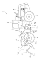
- FIG. 1 is a side view of the work machine 1 of the present embodiment.
- the work machine 1 of the present embodiment includes a vehicle body frame 2, a work machine 3, a pair of front tires 4, a cab 5, an engine room 6, a pair of rear tires 7, a steering system 8 (see FIG. 2), and a steering cylinder 9a. , 9b (an example of a hydraulic cylinder).
- front, “rear”, “right”, “left”, “top”, and “bottom” indicate the direction based on the state of looking forward from the driver's seat.
- vehicle width direction and “left-right direction” are synonymous.
- the work machine 1 performs earth and sand loading work using the work machine 3.
- the vehicle body frame 2 is a so-called articulated type, and has a front frame 11, a rear frame 12, and a connecting shaft portion 13.
- the front frame 11 is arranged in front of the rear frame 12.
- the front frame 11 corresponds to an example of the second frame
- the rear frame 12 corresponds to an example of the first frame.
- the connecting shaft portion 13 is provided at the center in the vehicle width direction, and connects the front frame 11 and the rear frame 12 so as to be swingable with each other.
- the pair of front tires 4 are attached to the left and right sides of the front frame 11. Further, the pair of rear tires 7 are attached to the left and right sides of the rear frame 12.
- the working machine 3 is driven by hydraulic oil from a working machine pump (not shown).
- the working machine 3 has a boom 14, a bucket 15, a lift cylinder 16, and a bucket cylinder 17.
- the boom 14 is mounted on the front frame 11.
- the bucket 15 is attached to the tip of the boom 14.
- the lift cylinder 16 and the bucket cylinder 17 are hydraulic cylinders. One end of the lift cylinder 16 is attached to the front frame 11, and the other end of the lift cylinder 16 is attached to the boom 14. The boom 14 swings up and down due to the expansion and contraction of the lift cylinder 16. One end of the bucket cylinder 17 is attached to the front frame 11, and the other end of the bucket cylinder 17 is attached to the bucket 15 via the bell crank 18. As the bucket cylinder 17 expands and contracts, the bucket 15 swings up and down.
- the cab 5 is mounted on the rear frame 12, and inside, a steering wheel 21 for steering operation (see FIG. 2), a lever for operating the working machine 3, various display devices, and the like are arranged. Has been done.
- the engine room 6 is located on the rear side of the cab 5 and on the rear frame 12, and houses the engine.
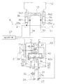
- FIG. 2 is a configuration diagram showing the steering system 8.
- the steering system 8 changes the steering angle, which is the rotation angle of the front frame 11 with respect to the rear frame 12, by changing the flow rate of the oil supplied to the steering cylinders 9a and 9b, and changes the traveling direction of the work machine 1. ..
- the pair of steering cylinders 9a and 9b are hydraulically driven.
- the pair of steering cylinders 9a and 9b are arranged side by side on the left and right sides in the vehicle width direction with the connecting shaft portion 13 interposed therebetween.
- the steering cylinder 9a is arranged on the left side of the connecting shaft portion 13.
- the steering cylinder 9b is arranged on the right side of the connecting shaft portion 13.
- One end of each of the steering cylinders 9a and 9b is attached to the front frame 11, and the other end of each is attached to the rear frame 12.
- the cylinder chamber of the steering cylinder 9a is divided into an extension chamber 9a1 and a contraction chamber 9a2 by a piston.
- the piston moves and the steering cylinder 9a expands, and when hydraulic oil is supplied to the contraction chamber 9a2, the piston moves and the steering cylinder 9a contracts.
- the cylinder chamber of the steering cylinder 9b is divided into an extension chamber 9b1 and a contraction chamber 9b2 by a piston.
- the piston moves and the steering cylinder 9b expands, and when hydraulic oil is supplied to the contraction chamber 9b2, the piston moves and the steering cylinder 9b contracts.
- the steering system 8 includes a steering wheel 21 (an example of an operating member), a steering valve 22, a variable displacement pump 23, a tank 24, cylinder stroke sensors 25a and 25b (an example of a frame angle detection unit), and a wheel angle sensor. It has 26 (an example of an operation speed detection unit and an example of an operation direction detection unit) and a controller 27.
- the steering wheel 21 is provided in the cab 5, and the steering valve 22 is operated by the operator rotating the steering wheel 21.
- the input shaft 21a of the steering wheel 21 is connected to the steering valve 22.
- the steering valve 22 is called an orbit roll (registered trademark) and is a fully hydraulic power steering unit.
- the steering valve 22 supplies hydraulic oil to the steering cylinders 9a and 9b in response to the operation of the steering wheel 21.
- the steering valve 22 has ports P, T, LS, R, L. The configuration of the steering valve 22 will be described later.
- the variable capacity pump 23 discharges hydraulic oil to the steering valve 22.
- the variable capacity pump 23 and the port P of the steering valve 22 are connected by a pipeline 31.
- the hydraulic oil discharged from the variable displacement pump 23 is supplied to the steering valve 22 via the pipeline 31.
- the variable displacement pump 23 has a swash plate 23a.
- the variable displacement pump 23 is configured so that the angle of the swash plate 23a can be changed by a signal from the controller 27.
- the maximum discharge amount of the variable capacity pump 23 can be changed by changing the angle of the swash plate 23a of the variable capacity pump 23. If the maximum discharge amount is reduced by changing the angle of the swash plate 23a, even if the pressure is increased, the discharge amount from the variable capacity pump 23 cannot be made larger than the predetermined amount, and the discharge amount may be reduced. can.
- the tank 24 stores hydraulic oil.
- the tank 24 and the port T of the steering valve 22 are connected by a pipeline 32.
- the hydraulic oil discharged from the steering cylinders 9a and 9b is discharged from the port T of the steering valve 22 to the tank 24.
- One end of the first supply path 33 is connected to the port R of the steering valve 22.
- the other end side of the first supply path 33 is branched into two.
- One of the two branched ends is connected to the extension chamber 9a1 of the steering cylinder 9a, and the other is connected to the contraction chamber 9b2 of the steering cylinder 9b.
- One end of the second supply path 34 is connected to the port L of the steering valve 22.
- the other end side of the second supply path 34 is branched into two.
- One of the two branched ends is connected to the contraction chamber 9a2 of the steering cylinder 9a, and the other is connected to the extension chamber 9b1 of the steering cylinder 9b.
- the steering valve 22 has a dirotor 41 and a directional control valve 42 (an example of a valve).
- the dirotor 41 has a metering mechanism.
- the dirotor 41 has a star and a ring in which the star is arranged inside.
- the star is connected to the input shaft 21a of the steering wheel 21 via a sleeve (not shown) fixed to the star and a spool 42a connected to the sleeve by a spring member.
- the dirotor 41 acts as a pump that pushes out the hydraulic oil while measuring it by rotating the star eccentrically in the ring.
- the directional control valve 42 is a three-position rotary type valve that switches in conjunction with the steering wheel 21 and the dirotor 41.
- the spool 42a is arranged at the position P1 with respect to the sleeve when the input shaft 21a is stopped, but when the steering wheel 21 is rotated to the right, the spool 42a with respect to the sleeve.
- the spool 42a switches to the position P3 with respect to the sleeve.
- the state in which the spool 42a is arranged at the position P2 with respect to the sleeve is an example of the first state.
- the state in which the spool 42a is arranged at the position P3 with respect to the sleeve is an example of the second state.
- the steering valve 22 has pipelines 43, 44, 45, 46, 47, 48, 49, 50.
- One end of the pipeline 43 is connected to the port P, and the other end is connected to the port of the directional control valve 42.
- a check valve 51 is provided in the pipeline 43.
- One end of the pipeline 44 is connected to the port T, and the other end is connected to the port of the directional control valve 42.
- One end of the pipeline 45 is connected to the dirotor 41, and the other end is connected to the port of the directional control valve 42.
- One end of the pipeline 46 is connected to the dirotor 41, and the other end is connected to the port of the directional control valve 42.
- One end of the pipeline 47 is connected to the port R, and the other end is connected to the port of the directional control valve 42.
- One end of the pipeline 48 is connected to the port L, and the other end is connected to the port of the directional control valve 42.
- One end of the pipeline 49 shown by the dotted line is connected to the LS port, and the other end is connected to the port of the directional control valve 42.
- a check valve 52 is provided in the pipeline 49.
- the pipeline 50 connects the pipeline 43 and the pipeline 44, and the pipeline 50 is provided with a check valve 53.
- a pipeline 35 connecting the LS port and the pipeline 32 is provided, and the pipeline 35 is provided with a relief valve 28.
- the hydraulic oil When the hydraulic oil is supplied to the first supply path 33, the hydraulic oil is supplied to the extension chamber 9a1 and the contraction chamber 9b2, and the front frame 11 rotates to the right with respect to the rear frame 12 about the connecting shaft portion 13. do. Further, hydraulic oil is discharged from the contraction chamber 9a2 and the extension chamber 9b1 through the second supply passage 34. The discharged hydraulic oil is discharged from the port L to the tank 24 through the pipeline 48 and the pipeline 44 of the directional control valve 42, and the pipeline 32.
- the spool 42a When the sleeve rotates due to the rotation of the star and the rotation angle of the spool 42a with respect to the sleeve becomes zero, the spool 42a is arranged at the position P1 with respect to the sleeve, and the discharge of hydraulic oil to the first supply path 33 is stopped. Will be done. As a result, the front frame 11 is maintained at a position corresponding to the operating angle of the steering wheel 21 with respect to the rear frame 12.
- the spool 42a connected to the input shaft 21a rotates with respect to the sleeve and moves to the position P3.
- the hydraulic oil supplied from the variable displacement pump 23 is supplied to the dirotor 41 through the pipeline 45 based on the relative rotation angle of the spool 42a with respect to the sleeve connected to the dirotor 41.
- the hydraulic oil delivered from the dirotor 41 due to the eccentric rotation of the star returns to the directional control valve 42 via the pipeline 46 and is supplied from the port L to the second supply passage 34 through the pipeline 48.
- the hydraulic oil When the hydraulic oil is supplied to the second supply path 34, the hydraulic oil is supplied to the contraction chamber 9a2 and the extension chamber 9b1, and the front frame 11 rotates to the left with respect to the rear frame 12 about the connecting shaft portion 13. do. Further, hydraulic oil is discharged from the extension chamber 9a1 and the contraction chamber 9b2 through the first supply passage 33. The discharged hydraulic oil is discharged from the port R to the tank 24 through the pipe line 47 and the pipe line 44 of the directional control valve 42 and the pipe line 32.
- the spool 42a When the sleeve is rotated by the rotation of the star and the rotation angle of the spool 42a with respect to the sleeve becomes zero, the spool 42a is arranged at the position P1 with respect to the sleeve, and the discharge of hydraulic oil to the second supply path 34 is stopped. Will be done. As a result, the front frame 11 is maintained at a position corresponding to the operating angle of the steering wheel 21 with respect to the rear frame 12.
- the hydraulic oil is supplied from the directional control valve 42 to the dirotor 41, but when the amount of the hydraulic oil is small, the force for assisting the operation of the steering wheel 21 becomes weak and the steering wheel 21 is operated. Becomes heavy.
- the cylinder stroke sensors 25a and 25b detect the strokes of the steering cylinders 9a and 9b.
- the cylinder stroke sensor 25a transmits a detection value regarding the stroke of the steering cylinder 9a to the controller 27.
- the cylinder stroke sensor 25b transmits the detection value regarding the stroke of the steering cylinder 9b to the controller 27.
- the wheel angle sensor 26 for example, a potentiometer can be used.
- the wheel angle sensor 26 detects the detection values related to the operation direction and the operation speed of the steering wheel 21 and transmits them to the controller 27.
- the detected value regarding the operating direction indicates whether the steering wheel 21 is rotated in the right direction or the left direction.
- the detected value regarding the operation speed indicates the rotation speed of the steering wheel 21.
- the controller 27 includes a processor and a storage device.
- the processor is, for example, a CPU (Central Processing Unit). Alternatively, the processor may be a processor different from the CPU.
- the processor executes a process for controlling the work machine 1 according to a program.
- the storage device includes a non-volatile memory such as ROM (Read Only Memory) and a volatile memory such as RAM (Random Access Memory).
- the storage device may include a hard disk or an auxiliary storage device such as an SSD (Solid State Drive).
- a storage device is an example of a recording medium that can be read by a non-transitory computer.
- the storage device stores programs and data for controlling the work machine 1.
- the storage device stores, for example, data of a terminal range described later and a predetermined threshold value of the operation speed.
- the detection values of the cylinder stroke sensors 25a and 25b and the detection values of the wheel angle sensor 26 are input to the controller 27.
- the controller 27 controls the angle of the swash plate 23a of the variable displacement pump 23 based on these detected values to reduce the discharge amount.
- the controller 27 calculates the steering angle ⁇ from the detection value of the cylinder stroke sensor 25a and the detection value of the cylinder stroke sensor 25b.
- the controller 27 determines whether or not the calculated steering angle is included in the end range of the steerable range.
- the steerable range and the end range will be described below.
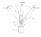
- FIG. 3 is a schematic diagram for showing the steerable range Ra of the front frame 11 with respect to the rear frame 12.
- the front frame 11, the rear frame 12, and the bucket 15 are schematically shown.
- the front frame 11 is rotatably connected to the rear frame 12 around the connecting shaft portion 13, but since the frames are in physical contact with each other, the front frame 11 has a steerable range Ra with respect to the rear frame 12. It can rotate within.
- the steering angle ⁇ when the front frame 11 is arranged along the front-rear direction with respect to the rear frame 12 is set to zero.
- the steering angle ⁇ is zero when the center line in the width direction of the rear frame 12 coincides with the center line in the width direction of the front frame 11.
- the steering angle ⁇ is an angle formed by the widthwise centerline of the front frame 11 with respect to the widthwise centerline of the rear frame 12.
- the steering angle ⁇ when the front frame 11 rotates to the right with respect to the rear frame 12 is set as a positive value
- the steering angle ⁇ when the front frame 11 rotates to the left with respect to the rear frame 12 is set to a negative value. The value of.
- the steering angle ⁇ is set to + ⁇ e degree to ⁇ e degree. That is, when the front frame 11 rotates to the right by ⁇ e with respect to the rear frame 12, it comes into contact with the rear frame 12 and cannot rotate further to the right. Further, when the front frame 11 rotates to the left side by ⁇ e degree with respect to the rear frame 12, it comes into contact with the rear frame 12 and cannot rotate further to the left side.
- the end range is a predetermined range near the end on the right side and a predetermined range near the end on the left side of the steerable range Ra.
- the predetermined range near the right end is defined as the end range Rre
- the predetermined range near the left end is defined as the end range Rle.
- the end range Rre can be set while the steering angle is between + ⁇ 1 and + ⁇ e. + ⁇ 1 is the threshold value of the right end range Rre.
- the terminal range Rre can be set to a maximum of about 5 degrees.
- the end range Rle can be set in the range where the steering angle is ⁇ 1 to ⁇ e. ⁇ 1 is the threshold value of the left end range Rle. Further, the end range Rle can be set to a maximum of about 5 degrees.
- the controller 27 determines whether the steering angle ⁇ calculated from the detected values of the cylinder stroke sensors 25a and 25b is within the range of + ⁇ 1 to + ⁇ e or ⁇ 1 to ⁇ e.
- the steering angle ⁇ is included in the end range Rre or the end range Rle, it can be determined that the front frame 11 and the rear frame 12 may come into contact with each other to generate an impact.
- the controller 27 determines whether or not the operation direction of the steering wheel 21 is a direction toward the end of the end range in which the front frame 11 is arranged, based on the detection value of the wheel angle sensor 26. For example, when the steering angle ⁇ is included in the end range Rre, it is determined whether or not the steering wheel 21 is operated toward the position (right side) where the steering angle ⁇ is + ⁇ e. Further, when the steering angle ⁇ is included in the end range Rle, it is determined whether or not the steering wheel 21 is operated toward the position (left side) where the steering angle ⁇ is ⁇ e.
- the front frame 11 is arranged in the end range, and it can be determined that the front frame 11 is operated toward the end of the end range. Therefore, when the front frame 11 is rotated in this state, the front frame 11 becomes the rear frame 12. It is possible to detect that an impact is generated in contact with.
- controller 27 determines whether or not the operating speed of the steering wheel 21 is equal to or higher than a predetermined threshold value based on the detection value related to the operating speed of the wheel angle sensor 26.
- the vibration at the time of contact also becomes large. Therefore, for example, the operator can set a predetermined threshold value according to the allowable vibration magnitude.
- the controller 27 when the steering angle is the end range, the steering wheel 21 is operated toward the end of the end range, and the operation speed of the steering wheel 21 is equal to or higher than a predetermined threshold value, the controller 27 is variable.
- the swash plate 23a of the variable capacity pump 23 is controlled so as to reduce the discharge amount from the capacity pump 23.
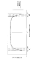
- FIG. 4 is a diagram showing the relationship between the steering angle and the angle of the swash plate 23a of the variable displacement pump 23.
- the graph when the discharge amount from the variable displacement pump 23 is reduced in the end range of the rotatable angle is shown by a thick line, and the graph when the discharge amount is not reduced is shown by a thin line.
- the discharge amount from the variable displacement pump 23 can be reduced, for example, by reducing the angle of the swash plate 23a at a predetermined rate (cc / rev) per second.
- dots are attached to the end range Rre in the range of the steering angle ⁇ of + ⁇ 1 to + ⁇ e and the end range Rle of the range of ⁇ 1 to ⁇ e.
- the angle of the swash plate 23a is changed sharply in the terminal ranges Rre and Rle, and the discharge amount from the variable capacity pump 23 is set to sharply decrease. There is.
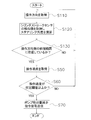
- FIG. 5 is a flow chart showing an example of a control method for the work machine 1.
- step S10 the controller 27 acquires the detection values related to the strokes of the cylinder stroke sensors 25a and 25b, and calculates the steering angle ⁇ .
- step S20 the controller 27 determines whether or not the calculated steering angle is included in the end range Rre or the end range Rle. If it is determined that the steering angle ⁇ is not included in the end range Rre or the end range Rle, the control returns to step S10, and the controller 27 repeats the acquisition of the detected values for the strokes of the cylinder stroke sensors 25a and 25b. On the other hand, if it is determined that the steering angle ⁇ is included in the end range Rre or the end range Rle, the control proceeds to step S30.
- step S30 the controller 27 acquires the operating direction of the steering wheel 21 based on the detection value regarding the operating direction of the wheel angle sensor 26.
- step S40 the controller 27 operates the steering wheel 21 toward the end of the end range in which the front frame 11 is located among the end range Rre and the end range Rle based on the operation direction. Is determined.
- step S20 when the controller 27 determines in step S20 that the steering angle ⁇ is included in the end range Rre, the steering wheel 21 is operated toward the steering angle + ⁇ e which is the end of the end range Rre. Judge whether or not. Further, when the controller 27 determines in step S20 that the steering angle ⁇ is arranged in the end range Rle, is the steering wheel 21 operated toward the steering angle ⁇ e which is the end of the end range Rle? Judge whether or not.
- step S40 If it is determined in step S40 that the steering wheel 21 is not operated toward the end of the end range in which the front frame 11 is located, the control returns to step S10. On the other hand, if it is determined that the steering wheel 21 is being operated toward the end of the end range in which the front frame 11 is located, the control proceeds to step S50.
- step S50 the controller 27 acquires the operating speed of the steering wheel 21 based on the detection value regarding the operating speed of the wheel angle sensor 26.
- step S60 the controller 27 determines whether the operating speed of the steering wheel 21 is equal to or higher than a predetermined threshold value. If it is determined in step S60 that the operation speed is less than the predetermined threshold value, the control returns to step S10.
- step S60 determines whether the operation speed is equal to or higher than the predetermined threshold value. If it is determined in step S60 that the operation speed is equal to or higher than the predetermined threshold value, the control proceeds to step S70.
- step S70 the controller 27 transmits a pump discharge amount reduction command signal toward the variable capacity pump 23.
- the variable displacement pump 23 changes the angle of the swash plate 23a so as to reduce the discharge amount.
- the discharge amount from the variable capacity pump 23 is reduced, the amount of hydraulic oil flowing into the dirotor 41 is also reduced, so that the operation of the steering wheel 21 becomes heavy. As a result, the operator can feel that the front frame 11 is arranged in the end range Rre and Rle in the steerable range Ra.
- the work machine 1 of the present embodiment includes a rear frame 12, a front frame 11, steering cylinders 9a and 9b, a direction control valve 42, a steering wheel 21, a variable displacement pump 23, and cylinder stroke sensors 25a and 25b. And a controller 27.
- the rear frame 12 is rotatably connected to the front frame 11.
- the steering cylinders 9a and 9b drive the front frame 11 with respect to the rear frame 12.
- the directional control valve 42 changes the amount of hydraulic oil supplied to the steering cylinders 9a and 9b.
- the steering wheel 21 operates the directional control valve 42.
- the variable displacement pump 23 discharges hydraulic oil to the directional control valve 42.
- the cylinder stroke sensors 25a and 25b are provided to detect the rotation angle of the front frame 11 with respect to the rear frame 12.
- the controller 27 reduces the discharge flow rate of the variable displacement pump 23 based on the detection values of the cylinder stroke sensors 25a and 25b.
- the controller 27 uses the terminal range Rre of the steerable range Ra in which the front frame 11 can rotate with respect to the rear frame 12 based on the detection values of the cylinder stroke sensors 25a and 25b. , Rle (an example of a predetermined range from the end), the discharge flow rate of the variable capacity pump 23 is reduced.
- the work machine 1 of the present embodiment further includes a wheel angle sensor 26.
- the wheel angle sensor 26 detects the operating direction of the steering wheel 21. Based on the detection value of the wheel angle sensor 26, the controller 27 determines that the steering wheel 21 is operated toward the rotation angle + ⁇ e of the end range Rre or the rotation angle ⁇ e of the end range Rle. If so, the discharge flow rate of the variable capacity pump 23 is reduced.
- the work machine 1 of the present embodiment further includes a wheel angle sensor 26.
- the controller 27 determines that the steering wheel 21 is operated at a speed equal to or higher than a predetermined threshold value based on the detection value of the wheel angle sensor 26, the controller 27 reduces the discharge flow rate of the variable displacement pump 23.
- the steering speed can be reduced only when necessary by reducing the discharge amount of the hydraulic oil from the variable capacity pump 23.
- variable displacement pump 23 has a swash plate 23a.
- the controller 27 reduces the discharge flow rate of the variable displacement pump 23 by changing the angle of the swash plate 23a.
- the maximum flow rate can be changed by changing the angle of the swash plate 23a.
- the discharge amount from the variable displacement pump can be reduced by changing the angle of the swash plate 23a to reduce the maximum flow rate.
- the work machine 1 of the present embodiment further includes a dirotor 41.
- the dirotor 41 changes the state of the directional control valve 42 based on the operation of the steering wheel 21.
- the directional control valve 42 connects the dirotor 41 and the variable displacement pump 23 in a state where the spool 42a is arranged at the position P2 with respect to the sleeve (an example of the first state), and supplies hydraulic oil to the steering cylinders 9a and 9b.
- the front frame 11 is driven to the right (an example of the first direction) by connecting the first supply path 33 and the dirotor 41, and the spool 42a is arranged at the position P3 with respect to the sleeve (second state).
- the dirotor 41 is connected to the variable displacement pump 23, the second supply path 34 for supplying hydraulic oil to the steering cylinders 9a and 9b is connected to the dirotor 41, and the front frame 11 is directed to the left (second direction). Drive to one example).
- the work machine 1 of the present embodiment is a wheel loader, and further includes a work machine 3.
- the working machine 3 is attached to the front side of the front frame 11.
- Step S10 is to detect the rotation angle of the front frame 11 rotatably connected to the rear frame 12.
- Step S70 discharges hydraulic oil to the directional control valve 42 that changes the supply amount of hydraulic oil to the steering cylinders 9a and 9b that drive the front frame 11 with respect to the rear frame 12 based on the detected rotation angle. It is to reduce the discharge amount of the variable capacity pump 23.
- the rotation angle of the front frame 11 with respect to the rear frame 12 is detected by using the detection values of the cylinder stroke sensors 25a and 25, but the rotation angle of the front frame 11 is not limited to this, and the rear frame 12 and the front frame may be detected.
- the rotation angle may be detected using the detection value of the frame angle sensor using a potentiometer or the like provided on the connecting shaft portion 13 of 11.
- position detection may be performed after direction detection.
- FIG. 6 is a diagram showing a control flow for performing position detection after direction detection.
- step S110 since the direction is detected after the position is detected, it is determined whether or not the direction is toward the end of the arranged end range at the time of the direction detection.
- step S110 when the direction detection is performed before the position detection, only the operation direction of the steering wheel 21 is detected in step S110 as shown in FIG. 6, and the detection values of the cylinder stroke sensors 25a and 25b are detected in step S120.
- the steering angle is detected, and it is determined in step S130 whether or not the vehicle is located in the terminal range on the operation direction side. If it is determined in step S130 that the front frame 11 is not located at the terminal position on the operation direction side, the control returns to step S110 and the operation direction is acquired again.
- steps S50, S60, and S70 are the same as those in the above embodiment, and when the operation speed is less than the predetermined threshold value in step S60, the control returns to step S110.
- the front frame 11 is arranged in the right end range Rre, and the operation speed is equal to or higher than a predetermined threshold. , The discharge amount from the variable capacity pump 23 is reduced. On the other hand, even when it is detected that the steering wheel 21 is rotated to the right, the control returns to step S110 when the front frame 11 is not arranged in the right end range Rre.
- the front frame 11 is arranged in the left end range Rle, and the variable capacitance is obtained when the operation speed is equal to or higher than a predetermined threshold value.
- the discharge amount from the pump 23 is reduced.
- the control returns to step S110 when the front frame 11 is not arranged in the left end range Rle.
- control is performed so as to reduce the discharge amount from the variable capacity pump 23 when the operation speed is equal to or higher than a predetermined threshold value, but the control is not limited to this, and it is based on the operation speed.
- the rate of change of the swash plate angle may be changed. For example, as the operation speed increases, the rate of change in the swash plate angle may be increased to increase the rate of decrease in the discharge amount.
- the end range Rre (+ ⁇ 1 to + ⁇ e) in the right direction and the end range Rle ( ⁇ 1 to ⁇ e) in the left direction are set to the same angle range, but may be different.
- the absolute value of the steering angle at the end in the right direction of the steerable range Ra and the absolute value of the steering angle at the end in the left direction may be different.
- in the above embodiment) may be different. ..
- the wheel loader is used as the work machine 1, but the present invention is not limited to the wheel loader, and an articulated dump truck, a motor grader, or the like may be used.
- the work machine of the present invention and the control method of the work machine have an effect of alleviating an impact at the end of steering, and are useful as a wheel loader or the like.
- Working machine 9a Steering cylinder 9b: Steering cylinder 21: Steering wheel 23: Variable capacity pump 42: Direction control valve
Landscapes
- Engineering & Computer Science (AREA)
- Mining & Mineral Resources (AREA)
- Structural Engineering (AREA)
- General Engineering & Computer Science (AREA)
- Civil Engineering (AREA)
- Transportation (AREA)
- Mechanical Engineering (AREA)
- Chemical & Material Sciences (AREA)
- Combustion & Propulsion (AREA)
- Physics & Mathematics (AREA)
- Fluid Mechanics (AREA)
- Power Steering Mechanism (AREA)
- Operation Control Of Excavators (AREA)
- Steering Control In Accordance With Driving Conditions (AREA)
Priority Applications (3)
| Application Number | Priority Date | Filing Date | Title |
|---|---|---|---|
| US17/918,678 US20230091679A1 (en) | 2020-07-10 | 2021-06-21 | Work machine and method for controlling work machine |
| EP21837128.4A EP4122802A4 (en) | 2020-07-10 | 2021-06-21 | CONSTRUCTION MACHINERY AND METHOD FOR CONTROLLING CONSTRUCTION MACHINERY |
| CN202180029762.2A CN115427640B (zh) | 2020-07-10 | 2021-06-21 | 作业机械以及作业机械的控制方法 |
Applications Claiming Priority (2)
| Application Number | Priority Date | Filing Date | Title |
|---|---|---|---|
| JP2020119125A JP7490478B2 (ja) | 2020-07-10 | 2020-07-10 | 作業機械、および作業機械の制御方法 |
| JP2020-119125 | 2020-07-10 |
Publications (1)
| Publication Number | Publication Date |
|---|---|
| WO2022009654A1 true WO2022009654A1 (ja) | 2022-01-13 |
Family
ID=79552956
Family Applications (1)
| Application Number | Title | Priority Date | Filing Date |
|---|---|---|---|
| PCT/JP2021/023443 Ceased WO2022009654A1 (ja) | 2020-07-10 | 2021-06-21 | 作業機械、および作業機械の制御方法 |
Country Status (5)
| Country | Link |
|---|---|
| US (1) | US20230091679A1 (enExample) |
| EP (1) | EP4122802A4 (enExample) |
| JP (1) | JP7490478B2 (enExample) |
| CN (1) | CN115427640B (enExample) |
| WO (1) | WO2022009654A1 (enExample) |
Families Citing this family (1)
| Publication number | Priority date | Publication date | Assignee | Title |
|---|---|---|---|---|
| JP2024048714A (ja) * | 2022-09-28 | 2024-04-09 | 株式会社小松製作所 | 作業機械、および作業機械の制御方法 |
Citations (5)
| Publication number | Priority date | Publication date | Assignee | Title |
|---|---|---|---|---|
| JPH0617440A (ja) * | 1992-07-02 | 1994-01-25 | Kubota Corp | バックホー装置の油圧操作構造 |
| JP2006348742A (ja) * | 2006-08-04 | 2006-12-28 | Komatsu Ltd | 作業車両の作業機用油圧ポンプの制御装置 |
| JP2008044428A (ja) | 2006-08-11 | 2008-02-28 | Komatsu Ltd | 車両のステアリング制御装置 |
| JP2008074393A (ja) * | 2006-09-01 | 2008-04-03 | Deere & Co | 制御された操向緩衝作用を有する連結式作業車両操向システムおよびそれに関連する方法 |
| JP2017087779A (ja) * | 2015-11-03 | 2017-05-25 | 日立建機株式会社 | ホイール式作業車両 |
Family Cites Families (29)
| Publication number | Priority date | Publication date | Assignee | Title |
|---|---|---|---|---|
| US3312301A (en) * | 1965-08-04 | 1967-04-04 | Int Harvester Co | Articulated vehicle steering system |
| DE2500137C3 (de) * | 1975-01-03 | 1980-06-19 | O & K Orenstein & Koppel Ag, 1000 Berlin | Hydrostatische Hilfskraftlenkung für SchaufeUader |
| US5117935A (en) * | 1990-12-21 | 1992-06-02 | Caterpillar Inc. | Load sensing hydrostatic steering system |
| US6039133A (en) * | 1997-11-17 | 2000-03-21 | Zulu; Joshua | Steering control system for an articulating work machine having a steering fluid cylinder and a fluid-powered differential |
| DE19963344C1 (de) * | 1999-12-27 | 2001-09-20 | Sauer Danfoss Nordborg As Nord | Verfahren zum Lenken eines Fahrzeugs |
| JP2003202001A (ja) * | 2002-01-08 | 2003-07-18 | Komatsu Ltd | 可変容量型流体装置と同流体装置を備えた作業機 |
| DE10256307A1 (de) * | 2002-12-03 | 2004-06-24 | O&K Orenstein & Koppel Ag | Hydraulische Lenkung für Fahrzeuge |
| JP4373238B2 (ja) * | 2003-08-19 | 2009-11-25 | 株式会社日立製作所 | パワーステアリング装置 |
| US6926113B2 (en) * | 2003-10-22 | 2005-08-09 | Cnh America Llc | Cushioned steering for articulated vehicle |
| WO2008075568A1 (ja) * | 2006-12-21 | 2008-06-26 | Hitachi Construction Machinery Co., Ltd. | 作業車両のステアリングシステム |
| WO2008081843A1 (ja) * | 2006-12-26 | 2008-07-10 | Hitachi Construction Machinery Co., Ltd. | 作業車両のステアリングシステム |
| JP4941928B2 (ja) * | 2006-12-26 | 2012-05-30 | 日立建機株式会社 | 作業車両のステアリングシステム |
| JP5388461B2 (ja) * | 2008-03-21 | 2014-01-15 | 株式会社小松製作所 | ステアリング操作装置 |
| BRPI0920016A2 (pt) * | 2008-12-17 | 2015-12-15 | Komatsu Mfg Co Ltd | dispositivo de controle para um veículo de transmissão hidrostática |
| JP5877616B2 (ja) * | 2012-03-02 | 2016-03-08 | ボッシュ・レックスロス株式会社 | 可変容量ポンプの制御方法 |
| CN202508146U (zh) * | 2012-03-21 | 2012-10-31 | 山东威猛工程机械有限公司 | 装载机液压转向限位装置 |
| JP6403386B2 (ja) * | 2014-01-15 | 2018-10-10 | 株式会社小松製作所 | 作業車両及び作業車両の制御方法 |
| WO2015156708A1 (en) * | 2014-04-08 | 2015-10-15 | Volvo Construction Equipment Ab | Steering and feeedback assembly for an articulated vehicle |
| US10518803B2 (en) * | 2015-10-30 | 2019-12-31 | Komatsu Ltd. | Work vehicle and method for controlling work vehicle |
| DE102016002443A1 (de) * | 2016-02-29 | 2017-08-31 | Bomag Gmbh | Lenkeinrichtung, Baumaschine mit einer Lenkeinrichtung und Verfahren zum Lenken einer lenkbaren Maschine |
| US11167791B2 (en) * | 2016-05-31 | 2021-11-09 | Komatsu Ltd. | Work vehicle and method for controlling work vehicle |
| US9925983B2 (en) * | 2016-07-18 | 2018-03-27 | Caterpillar Inc. | System and method to eliminate or reduce frame contact during operation of articulated machine |
| WO2018038266A1 (ja) * | 2016-08-26 | 2018-03-01 | 株式会社小松製作所 | 作業車両および作業車両の制御方法 |
| US10850767B2 (en) * | 2016-08-26 | 2020-12-01 | Komatsu Ltd. | Work vehicle and control method for work vehicle |
| JP6996900B2 (ja) * | 2017-08-11 | 2022-01-17 | 株式会社小松製作所 | 作業車両 |
| JP6858723B2 (ja) * | 2018-03-28 | 2021-04-14 | 日立建機株式会社 | ホイールローダ |
| JP7223526B2 (ja) * | 2018-08-13 | 2023-02-16 | 株式会社小松製作所 | 作業車両 |
| CN110777874A (zh) * | 2019-10-29 | 2020-02-11 | 义乌市深研智能科技有限公司 | 一种装载机防撞击控制系统 |
| CN111155588A (zh) * | 2020-01-10 | 2020-05-15 | 重庆智邦工程机械(集团)有限公司 | 一种履带式挖掘机转向自动变速控制系统及控制方法 |
-
2020
- 2020-07-10 JP JP2020119125A patent/JP7490478B2/ja active Active
-
2021
- 2021-06-21 US US17/918,678 patent/US20230091679A1/en active Pending
- 2021-06-21 EP EP21837128.4A patent/EP4122802A4/en active Pending
- 2021-06-21 WO PCT/JP2021/023443 patent/WO2022009654A1/ja not_active Ceased
- 2021-06-21 CN CN202180029762.2A patent/CN115427640B/zh active Active
Patent Citations (5)
| Publication number | Priority date | Publication date | Assignee | Title |
|---|---|---|---|---|
| JPH0617440A (ja) * | 1992-07-02 | 1994-01-25 | Kubota Corp | バックホー装置の油圧操作構造 |
| JP2006348742A (ja) * | 2006-08-04 | 2006-12-28 | Komatsu Ltd | 作業車両の作業機用油圧ポンプの制御装置 |
| JP2008044428A (ja) | 2006-08-11 | 2008-02-28 | Komatsu Ltd | 車両のステアリング制御装置 |
| JP2008074393A (ja) * | 2006-09-01 | 2008-04-03 | Deere & Co | 制御された操向緩衝作用を有する連結式作業車両操向システムおよびそれに関連する方法 |
| JP2017087779A (ja) * | 2015-11-03 | 2017-05-25 | 日立建機株式会社 | ホイール式作業車両 |
Non-Patent Citations (1)
| Title |
|---|
| See also references of EP4122802A4 |
Also Published As
| Publication number | Publication date |
|---|---|
| JP7490478B2 (ja) | 2024-05-27 |
| EP4122802A4 (en) | 2024-06-12 |
| US20230091679A1 (en) | 2023-03-23 |
| CN115427640B (zh) | 2024-07-09 |
| EP4122802A1 (en) | 2023-01-25 |
| CN115427640A (zh) | 2022-12-02 |
| JP2022022892A (ja) | 2022-02-07 |
Similar Documents
| Publication | Publication Date | Title |
|---|---|---|
| CN107406101B (zh) | 作业车辆以及作业车辆的控制方法 | |
| JP6716594B2 (ja) | 作業車両および作業車両の制御方法 | |
| CN108698635B (zh) | 作业车辆及作业车辆的控制方法 | |
| CN108698636B (zh) | 作业车辆及作业车辆的控制方法 | |
| JP6858723B2 (ja) | ホイールローダ | |
| JP7068983B2 (ja) | 作業車両 | |
| JP7693893B2 (ja) | 作業機 | |
| JP2006219975A (ja) | 移動機械のための半能動走行制御 | |
| CN115516173B (zh) | 工程机械以及用于控制工程机械的方法 | |
| WO2022009654A1 (ja) | 作業機械、および作業機械の制御方法 | |
| WO2022201676A1 (ja) | 作業機械 | |
| JP7034010B2 (ja) | ホイール式作業機械 | |
| EP4549288A1 (en) | Work machine and method for controlling work machine | |
| JP7703730B2 (ja) | 作業機 | |
| JP7478114B2 (ja) | 作業機 | |
| CN115151473B (zh) | 转向装置以及作业机械 | |
| JP7764736B2 (ja) | 走行式作業機械の油圧駆動装置 | |
| JP2022033101A (ja) | 作業機 | |
| JP2020008029A (ja) | 流体圧制御システム | |
| JP2021050537A (ja) | 作業車両 | |
| JP2022033076A (ja) | 作業機 | |
| JP2005343245A (ja) | 全油圧式パワーステアリング装置 |
Legal Events
| Date | Code | Title | Description |
|---|---|---|---|
| 121 | Ep: the epo has been informed by wipo that ep was designated in this application |
Ref document number: 21837128 Country of ref document: EP Kind code of ref document: A1 |
|
| ENP | Entry into the national phase |
Ref document number: 2021837128 Country of ref document: EP Effective date: 20221018 |
|
| NENP | Non-entry into the national phase |
Ref country code: DE |