WO2022009654A1 - 作業機械、および作業機械の制御方法 - Google Patents
作業機械、および作業機械の制御方法 Download PDFInfo
- Publication number
- WO2022009654A1 WO2022009654A1 PCT/JP2021/023443 JP2021023443W WO2022009654A1 WO 2022009654 A1 WO2022009654 A1 WO 2022009654A1 JP 2021023443 W JP2021023443 W JP 2021023443W WO 2022009654 A1 WO2022009654 A1 WO 2022009654A1
- Authority
- WO
- WIPO (PCT)
- Prior art keywords
- frame
- steering
- work machine
- hydraulic oil
- angle
- Prior art date
Links
Images

Classifications
-
- B—PERFORMING OPERATIONS; TRANSPORTING
- B62—LAND VEHICLES FOR TRAVELLING OTHERWISE THAN ON RAILS
- B62D—MOTOR VEHICLES; TRAILERS
- B62D12/00—Steering specially adapted for vehicles operating in tandem or having pivotally connected frames
-
- B—PERFORMING OPERATIONS; TRANSPORTING
- B62—LAND VEHICLES FOR TRAVELLING OTHERWISE THAN ON RAILS
- B62D—MOTOR VEHICLES; TRAILERS
- B62D5/00—Power-assisted or power-driven steering
- B62D5/06—Power-assisted or power-driven steering fluid, i.e. using a pressurised fluid for most or all the force required for steering a vehicle
- B62D5/065—Power-assisted or power-driven steering fluid, i.e. using a pressurised fluid for most or all the force required for steering a vehicle characterised by specially adapted means for varying pressurised fluid supply based on need, e.g. on-demand, variable assist
-
- B—PERFORMING OPERATIONS; TRANSPORTING
- B62—LAND VEHICLES FOR TRAVELLING OTHERWISE THAN ON RAILS
- B62D—MOTOR VEHICLES; TRAILERS
- B62D5/00—Power-assisted or power-driven steering
- B62D5/06—Power-assisted or power-driven steering fluid, i.e. using a pressurised fluid for most or all the force required for steering a vehicle
- B62D5/10—Power-assisted or power-driven steering fluid, i.e. using a pressurised fluid for most or all the force required for steering a vehicle characterised by type of power unit
- B62D5/12—Piston and cylinder
-
- E—FIXED CONSTRUCTIONS
- E02—HYDRAULIC ENGINEERING; FOUNDATIONS; SOIL SHIFTING
- E02F—DREDGING; SOIL-SHIFTING
- E02F9/00—Component parts of dredgers or soil-shifting machines, not restricted to one of the kinds covered by groups E02F3/00 - E02F7/00
- E02F9/08—Superstructures; Supports for superstructures
- E02F9/0841—Articulated frame, i.e. having at least one pivot point between two travelling gear units
-
- E—FIXED CONSTRUCTIONS
- E02—HYDRAULIC ENGINEERING; FOUNDATIONS; SOIL SHIFTING
- E02F—DREDGING; SOIL-SHIFTING
- E02F9/00—Component parts of dredgers or soil-shifting machines, not restricted to one of the kinds covered by groups E02F3/00 - E02F7/00
- E02F9/20—Drives; Control devices
-
- E—FIXED CONSTRUCTIONS
- E02—HYDRAULIC ENGINEERING; FOUNDATIONS; SOIL SHIFTING
- E02F—DREDGING; SOIL-SHIFTING
- E02F9/00—Component parts of dredgers or soil-shifting machines, not restricted to one of the kinds covered by groups E02F3/00 - E02F7/00
- E02F9/20—Drives; Control devices
- E02F9/22—Hydraulic or pneumatic drives
- E02F9/2221—Control of flow rate; Load sensing arrangements
- E02F9/2232—Control of flow rate; Load sensing arrangements using one or more variable displacement pumps
- E02F9/2235—Control of flow rate; Load sensing arrangements using one or more variable displacement pumps including an electronic controller
-
- E—FIXED CONSTRUCTIONS
- E02—HYDRAULIC ENGINEERING; FOUNDATIONS; SOIL SHIFTING
- E02F—DREDGING; SOIL-SHIFTING
- E02F9/00—Component parts of dredgers or soil-shifting machines, not restricted to one of the kinds covered by groups E02F3/00 - E02F7/00
- E02F9/20—Drives; Control devices
- E02F9/22—Hydraulic or pneumatic drives
- E02F9/225—Control of steering, e.g. for hydraulic motors driving the vehicle tracks
-
- B—PERFORMING OPERATIONS; TRANSPORTING
- B62—LAND VEHICLES FOR TRAVELLING OTHERWISE THAN ON RAILS
- B62D—MOTOR VEHICLES; TRAILERS
- B62D5/00—Power-assisted or power-driven steering
- B62D5/06—Power-assisted or power-driven steering fluid, i.e. using a pressurised fluid for most or all the force required for steering a vehicle
- B62D5/061—Power-assisted or power-driven steering fluid, i.e. using a pressurised fluid for most or all the force required for steering a vehicle provided with effort, steering lock, or end-of-stroke limiters
Definitions
- the present invention relates to a work machine and a method for controlling the work machine.
- a work machine having a refraction mechanism such as a wheel loader has independent front and rear frames, and when performing steering operation, the vehicle bends due to expansion and contraction of the hydraulic cylinder for steering that connects the front and rear frames.
- the hydraulic oil that drives this hydraulic cylinder is supplied by a hydraulic pump via a steering valve.
- the above stop valve cannot be used because the flow rate is large and the pressure is large.
- the work machine includes a first frame, a second frame, a hydraulic cylinder, a valve, an operating member, a variable displacement pump, a frame angle detection unit, and a controller.
- the second frame is rotatably connected to the first frame.
- the hydraulic cylinder drives the second frame with respect to the first frame.
- the valve changes the amount of hydraulic oil supplied to the hydraulic cylinder.
- the operating member operates the valve.
- the variable displacement pump discharges hydraulic oil to the valve.
- the frame angle detection unit is provided to detect the rotation angle of the second frame with respect to the first frame.
- the controller reduces the discharge flow rate of the variable displacement pump based on the detection value of the frame angle detection unit.
- the work machine control method includes the following processing.
- the first process is to detect the rotation angle of the second frame rotatably connected to the first frame.
- the second process is a variable displacement pump that discharges hydraulic oil to a valve that changes the amount of hydraulic oil supplied to the hydraulic cylinder that drives the second frame with respect to the first frame, based on the detected rotation angle. Is to reduce the discharge amount of. (The invention's effect)
- the side view which shows the work machine of embodiment which concerns on this disclosure The figure which shows the structure of the steering system of FIG.
- the figure which shows the rotatable range of the front frame with respect to the rear frame The figure which shows the relationship between the rotation angle of a front frame with respect to a rear frame, and the angle of a swash plate of a variable capacity pump.
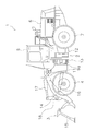
- FIG. 1 is a side view of the work machine 1 of the present embodiment.
- the work machine 1 of the present embodiment includes a vehicle body frame 2, a work machine 3, a pair of front tires 4, a cab 5, an engine room 6, a pair of rear tires 7, a steering system 8 (see FIG. 2), and a steering cylinder 9a. , 9b (an example of a hydraulic cylinder).
- front, “rear”, “right”, “left”, “top”, and “bottom” indicate the direction based on the state of looking forward from the driver's seat.
- vehicle width direction and “left-right direction” are synonymous.
- the work machine 1 performs earth and sand loading work using the work machine 3.
- the vehicle body frame 2 is a so-called articulated type, and has a front frame 11, a rear frame 12, and a connecting shaft portion 13.
- the front frame 11 is arranged in front of the rear frame 12.
- the front frame 11 corresponds to an example of the second frame
- the rear frame 12 corresponds to an example of the first frame.
- the connecting shaft portion 13 is provided at the center in the vehicle width direction, and connects the front frame 11 and the rear frame 12 so as to be swingable with each other.
- the pair of front tires 4 are attached to the left and right sides of the front frame 11. Further, the pair of rear tires 7 are attached to the left and right sides of the rear frame 12.
- the working machine 3 is driven by hydraulic oil from a working machine pump (not shown).
- the working machine 3 has a boom 14, a bucket 15, a lift cylinder 16, and a bucket cylinder 17.
- the boom 14 is mounted on the front frame 11.
- the bucket 15 is attached to the tip of the boom 14.
- the lift cylinder 16 and the bucket cylinder 17 are hydraulic cylinders. One end of the lift cylinder 16 is attached to the front frame 11, and the other end of the lift cylinder 16 is attached to the boom 14. The boom 14 swings up and down due to the expansion and contraction of the lift cylinder 16. One end of the bucket cylinder 17 is attached to the front frame 11, and the other end of the bucket cylinder 17 is attached to the bucket 15 via the bell crank 18. As the bucket cylinder 17 expands and contracts, the bucket 15 swings up and down.
- the cab 5 is mounted on the rear frame 12, and inside, a steering wheel 21 for steering operation (see FIG. 2), a lever for operating the working machine 3, various display devices, and the like are arranged. Has been done.
- the engine room 6 is located on the rear side of the cab 5 and on the rear frame 12, and houses the engine.
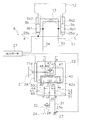
- FIG. 2 is a configuration diagram showing the steering system 8.
- the steering system 8 changes the steering angle, which is the rotation angle of the front frame 11 with respect to the rear frame 12, by changing the flow rate of the oil supplied to the steering cylinders 9a and 9b, and changes the traveling direction of the work machine 1. ..
- the pair of steering cylinders 9a and 9b are hydraulically driven.
- the pair of steering cylinders 9a and 9b are arranged side by side on the left and right sides in the vehicle width direction with the connecting shaft portion 13 interposed therebetween.
- the steering cylinder 9a is arranged on the left side of the connecting shaft portion 13.
- the steering cylinder 9b is arranged on the right side of the connecting shaft portion 13.
- One end of each of the steering cylinders 9a and 9b is attached to the front frame 11, and the other end of each is attached to the rear frame 12.
- the cylinder chamber of the steering cylinder 9a is divided into an extension chamber 9a1 and a contraction chamber 9a2 by a piston.
- the piston moves and the steering cylinder 9a expands, and when hydraulic oil is supplied to the contraction chamber 9a2, the piston moves and the steering cylinder 9a contracts.
- the cylinder chamber of the steering cylinder 9b is divided into an extension chamber 9b1 and a contraction chamber 9b2 by a piston.
- the piston moves and the steering cylinder 9b expands, and when hydraulic oil is supplied to the contraction chamber 9b2, the piston moves and the steering cylinder 9b contracts.
- the steering system 8 includes a steering wheel 21 (an example of an operating member), a steering valve 22, a variable displacement pump 23, a tank 24, cylinder stroke sensors 25a and 25b (an example of a frame angle detection unit), and a wheel angle sensor. It has 26 (an example of an operation speed detection unit and an example of an operation direction detection unit) and a controller 27.
- the steering wheel 21 is provided in the cab 5, and the steering valve 22 is operated by the operator rotating the steering wheel 21.
- the input shaft 21a of the steering wheel 21 is connected to the steering valve 22.
- the steering valve 22 is called an orbit roll (registered trademark) and is a fully hydraulic power steering unit.
- the steering valve 22 supplies hydraulic oil to the steering cylinders 9a and 9b in response to the operation of the steering wheel 21.
- the steering valve 22 has ports P, T, LS, R, L. The configuration of the steering valve 22 will be described later.
- the variable capacity pump 23 discharges hydraulic oil to the steering valve 22.
- the variable capacity pump 23 and the port P of the steering valve 22 are connected by a pipeline 31.
- the hydraulic oil discharged from the variable displacement pump 23 is supplied to the steering valve 22 via the pipeline 31.
- the variable displacement pump 23 has a swash plate 23a.
- the variable displacement pump 23 is configured so that the angle of the swash plate 23a can be changed by a signal from the controller 27.
- the maximum discharge amount of the variable capacity pump 23 can be changed by changing the angle of the swash plate 23a of the variable capacity pump 23. If the maximum discharge amount is reduced by changing the angle of the swash plate 23a, even if the pressure is increased, the discharge amount from the variable capacity pump 23 cannot be made larger than the predetermined amount, and the discharge amount may be reduced. can.
- the tank 24 stores hydraulic oil.
- the tank 24 and the port T of the steering valve 22 are connected by a pipeline 32.
- the hydraulic oil discharged from the steering cylinders 9a and 9b is discharged from the port T of the steering valve 22 to the tank 24.
- One end of the first supply path 33 is connected to the port R of the steering valve 22.
- the other end side of the first supply path 33 is branched into two.
- One of the two branched ends is connected to the extension chamber 9a1 of the steering cylinder 9a, and the other is connected to the contraction chamber 9b2 of the steering cylinder 9b.
- One end of the second supply path 34 is connected to the port L of the steering valve 22.
- the other end side of the second supply path 34 is branched into two.
- One of the two branched ends is connected to the contraction chamber 9a2 of the steering cylinder 9a, and the other is connected to the extension chamber 9b1 of the steering cylinder 9b.
- the steering valve 22 has a dirotor 41 and a directional control valve 42 (an example of a valve).
- the dirotor 41 has a metering mechanism.
- the dirotor 41 has a star and a ring in which the star is arranged inside.
- the star is connected to the input shaft 21a of the steering wheel 21 via a sleeve (not shown) fixed to the star and a spool 42a connected to the sleeve by a spring member.
- the dirotor 41 acts as a pump that pushes out the hydraulic oil while measuring it by rotating the star eccentrically in the ring.
- the directional control valve 42 is a three-position rotary type valve that switches in conjunction with the steering wheel 21 and the dirotor 41.
- the spool 42a is arranged at the position P1 with respect to the sleeve when the input shaft 21a is stopped, but when the steering wheel 21 is rotated to the right, the spool 42a with respect to the sleeve.
- the spool 42a switches to the position P3 with respect to the sleeve.
- the state in which the spool 42a is arranged at the position P2 with respect to the sleeve is an example of the first state.
- the state in which the spool 42a is arranged at the position P3 with respect to the sleeve is an example of the second state.
- the steering valve 22 has pipelines 43, 44, 45, 46, 47, 48, 49, 50.
- One end of the pipeline 43 is connected to the port P, and the other end is connected to the port of the directional control valve 42.
- a check valve 51 is provided in the pipeline 43.
- One end of the pipeline 44 is connected to the port T, and the other end is connected to the port of the directional control valve 42.
- One end of the pipeline 45 is connected to the dirotor 41, and the other end is connected to the port of the directional control valve 42.
- One end of the pipeline 46 is connected to the dirotor 41, and the other end is connected to the port of the directional control valve 42.
- One end of the pipeline 47 is connected to the port R, and the other end is connected to the port of the directional control valve 42.
- One end of the pipeline 48 is connected to the port L, and the other end is connected to the port of the directional control valve 42.
- One end of the pipeline 49 shown by the dotted line is connected to the LS port, and the other end is connected to the port of the directional control valve 42.
- a check valve 52 is provided in the pipeline 49.
- the pipeline 50 connects the pipeline 43 and the pipeline 44, and the pipeline 50 is provided with a check valve 53.
- a pipeline 35 connecting the LS port and the pipeline 32 is provided, and the pipeline 35 is provided with a relief valve 28.
- the hydraulic oil When the hydraulic oil is supplied to the first supply path 33, the hydraulic oil is supplied to the extension chamber 9a1 and the contraction chamber 9b2, and the front frame 11 rotates to the right with respect to the rear frame 12 about the connecting shaft portion 13. do. Further, hydraulic oil is discharged from the contraction chamber 9a2 and the extension chamber 9b1 through the second supply passage 34. The discharged hydraulic oil is discharged from the port L to the tank 24 through the pipeline 48 and the pipeline 44 of the directional control valve 42, and the pipeline 32.
- the spool 42a When the sleeve rotates due to the rotation of the star and the rotation angle of the spool 42a with respect to the sleeve becomes zero, the spool 42a is arranged at the position P1 with respect to the sleeve, and the discharge of hydraulic oil to the first supply path 33 is stopped. Will be done. As a result, the front frame 11 is maintained at a position corresponding to the operating angle of the steering wheel 21 with respect to the rear frame 12.
- the spool 42a connected to the input shaft 21a rotates with respect to the sleeve and moves to the position P3.
- the hydraulic oil supplied from the variable displacement pump 23 is supplied to the dirotor 41 through the pipeline 45 based on the relative rotation angle of the spool 42a with respect to the sleeve connected to the dirotor 41.
- the hydraulic oil delivered from the dirotor 41 due to the eccentric rotation of the star returns to the directional control valve 42 via the pipeline 46 and is supplied from the port L to the second supply passage 34 through the pipeline 48.
- the hydraulic oil When the hydraulic oil is supplied to the second supply path 34, the hydraulic oil is supplied to the contraction chamber 9a2 and the extension chamber 9b1, and the front frame 11 rotates to the left with respect to the rear frame 12 about the connecting shaft portion 13. do. Further, hydraulic oil is discharged from the extension chamber 9a1 and the contraction chamber 9b2 through the first supply passage 33. The discharged hydraulic oil is discharged from the port R to the tank 24 through the pipe line 47 and the pipe line 44 of the directional control valve 42 and the pipe line 32.
- the spool 42a When the sleeve is rotated by the rotation of the star and the rotation angle of the spool 42a with respect to the sleeve becomes zero, the spool 42a is arranged at the position P1 with respect to the sleeve, and the discharge of hydraulic oil to the second supply path 34 is stopped. Will be done. As a result, the front frame 11 is maintained at a position corresponding to the operating angle of the steering wheel 21 with respect to the rear frame 12.
- the hydraulic oil is supplied from the directional control valve 42 to the dirotor 41, but when the amount of the hydraulic oil is small, the force for assisting the operation of the steering wheel 21 becomes weak and the steering wheel 21 is operated. Becomes heavy.
- the cylinder stroke sensors 25a and 25b detect the strokes of the steering cylinders 9a and 9b.
- the cylinder stroke sensor 25a transmits a detection value regarding the stroke of the steering cylinder 9a to the controller 27.
- the cylinder stroke sensor 25b transmits the detection value regarding the stroke of the steering cylinder 9b to the controller 27.
- the wheel angle sensor 26 for example, a potentiometer can be used.
- the wheel angle sensor 26 detects the detection values related to the operation direction and the operation speed of the steering wheel 21 and transmits them to the controller 27.
- the detected value regarding the operating direction indicates whether the steering wheel 21 is rotated in the right direction or the left direction.
- the detected value regarding the operation speed indicates the rotation speed of the steering wheel 21.
- the controller 27 includes a processor and a storage device.
- the processor is, for example, a CPU (Central Processing Unit). Alternatively, the processor may be a processor different from the CPU.
- the processor executes a process for controlling the work machine 1 according to a program.
- the storage device includes a non-volatile memory such as ROM (Read Only Memory) and a volatile memory such as RAM (Random Access Memory).
- the storage device may include a hard disk or an auxiliary storage device such as an SSD (Solid State Drive).
- a storage device is an example of a recording medium that can be read by a non-transitory computer.
- the storage device stores programs and data for controlling the work machine 1.
- the storage device stores, for example, data of a terminal range described later and a predetermined threshold value of the operation speed.
- the detection values of the cylinder stroke sensors 25a and 25b and the detection values of the wheel angle sensor 26 are input to the controller 27.
- the controller 27 controls the angle of the swash plate 23a of the variable displacement pump 23 based on these detected values to reduce the discharge amount.
- the controller 27 calculates the steering angle ⁇ from the detection value of the cylinder stroke sensor 25a and the detection value of the cylinder stroke sensor 25b.
- the controller 27 determines whether or not the calculated steering angle is included in the end range of the steerable range.
- the steerable range and the end range will be described below.
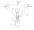
- FIG. 3 is a schematic diagram for showing the steerable range Ra of the front frame 11 with respect to the rear frame 12.
- the front frame 11, the rear frame 12, and the bucket 15 are schematically shown.
- the front frame 11 is rotatably connected to the rear frame 12 around the connecting shaft portion 13, but since the frames are in physical contact with each other, the front frame 11 has a steerable range Ra with respect to the rear frame 12. It can rotate within.
- the steering angle ⁇ when the front frame 11 is arranged along the front-rear direction with respect to the rear frame 12 is set to zero.
- the steering angle ⁇ is zero when the center line in the width direction of the rear frame 12 coincides with the center line in the width direction of the front frame 11.
- the steering angle ⁇ is an angle formed by the widthwise centerline of the front frame 11 with respect to the widthwise centerline of the rear frame 12.
- the steering angle ⁇ when the front frame 11 rotates to the right with respect to the rear frame 12 is set as a positive value
- the steering angle ⁇ when the front frame 11 rotates to the left with respect to the rear frame 12 is set to a negative value. The value of.
- the steering angle ⁇ is set to + ⁇ e degree to ⁇ e degree. That is, when the front frame 11 rotates to the right by ⁇ e with respect to the rear frame 12, it comes into contact with the rear frame 12 and cannot rotate further to the right. Further, when the front frame 11 rotates to the left side by ⁇ e degree with respect to the rear frame 12, it comes into contact with the rear frame 12 and cannot rotate further to the left side.
- the end range is a predetermined range near the end on the right side and a predetermined range near the end on the left side of the steerable range Ra.
- the predetermined range near the right end is defined as the end range Rre
- the predetermined range near the left end is defined as the end range Rle.
- the end range Rre can be set while the steering angle is between + ⁇ 1 and + ⁇ e. + ⁇ 1 is the threshold value of the right end range Rre.
- the terminal range Rre can be set to a maximum of about 5 degrees.
- the end range Rle can be set in the range where the steering angle is ⁇ 1 to ⁇ e. ⁇ 1 is the threshold value of the left end range Rle. Further, the end range Rle can be set to a maximum of about 5 degrees.
- the controller 27 determines whether the steering angle ⁇ calculated from the detected values of the cylinder stroke sensors 25a and 25b is within the range of + ⁇ 1 to + ⁇ e or ⁇ 1 to ⁇ e.
- the steering angle ⁇ is included in the end range Rre or the end range Rle, it can be determined that the front frame 11 and the rear frame 12 may come into contact with each other to generate an impact.
- the controller 27 determines whether or not the operation direction of the steering wheel 21 is a direction toward the end of the end range in which the front frame 11 is arranged, based on the detection value of the wheel angle sensor 26. For example, when the steering angle ⁇ is included in the end range Rre, it is determined whether or not the steering wheel 21 is operated toward the position (right side) where the steering angle ⁇ is + ⁇ e. Further, when the steering angle ⁇ is included in the end range Rle, it is determined whether or not the steering wheel 21 is operated toward the position (left side) where the steering angle ⁇ is ⁇ e.
- the front frame 11 is arranged in the end range, and it can be determined that the front frame 11 is operated toward the end of the end range. Therefore, when the front frame 11 is rotated in this state, the front frame 11 becomes the rear frame 12. It is possible to detect that an impact is generated in contact with.
- controller 27 determines whether or not the operating speed of the steering wheel 21 is equal to or higher than a predetermined threshold value based on the detection value related to the operating speed of the wheel angle sensor 26.
- the vibration at the time of contact also becomes large. Therefore, for example, the operator can set a predetermined threshold value according to the allowable vibration magnitude.
- the controller 27 when the steering angle is the end range, the steering wheel 21 is operated toward the end of the end range, and the operation speed of the steering wheel 21 is equal to or higher than a predetermined threshold value, the controller 27 is variable.
- the swash plate 23a of the variable capacity pump 23 is controlled so as to reduce the discharge amount from the capacity pump 23.
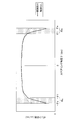
- FIG. 4 is a diagram showing the relationship between the steering angle and the angle of the swash plate 23a of the variable displacement pump 23.
- the graph when the discharge amount from the variable displacement pump 23 is reduced in the end range of the rotatable angle is shown by a thick line, and the graph when the discharge amount is not reduced is shown by a thin line.
- the discharge amount from the variable displacement pump 23 can be reduced, for example, by reducing the angle of the swash plate 23a at a predetermined rate (cc / rev) per second.
- dots are attached to the end range Rre in the range of the steering angle ⁇ of + ⁇ 1 to + ⁇ e and the end range Rle of the range of ⁇ 1 to ⁇ e.
- the angle of the swash plate 23a is changed sharply in the terminal ranges Rre and Rle, and the discharge amount from the variable capacity pump 23 is set to sharply decrease. There is.
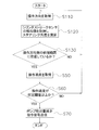
- FIG. 5 is a flow chart showing an example of a control method for the work machine 1.
- step S10 the controller 27 acquires the detection values related to the strokes of the cylinder stroke sensors 25a and 25b, and calculates the steering angle ⁇ .
- step S20 the controller 27 determines whether or not the calculated steering angle is included in the end range Rre or the end range Rle. If it is determined that the steering angle ⁇ is not included in the end range Rre or the end range Rle, the control returns to step S10, and the controller 27 repeats the acquisition of the detected values for the strokes of the cylinder stroke sensors 25a and 25b. On the other hand, if it is determined that the steering angle ⁇ is included in the end range Rre or the end range Rle, the control proceeds to step S30.
- step S30 the controller 27 acquires the operating direction of the steering wheel 21 based on the detection value regarding the operating direction of the wheel angle sensor 26.
- step S40 the controller 27 operates the steering wheel 21 toward the end of the end range in which the front frame 11 is located among the end range Rre and the end range Rle based on the operation direction. Is determined.
- step S20 when the controller 27 determines in step S20 that the steering angle ⁇ is included in the end range Rre, the steering wheel 21 is operated toward the steering angle + ⁇ e which is the end of the end range Rre. Judge whether or not. Further, when the controller 27 determines in step S20 that the steering angle ⁇ is arranged in the end range Rle, is the steering wheel 21 operated toward the steering angle ⁇ e which is the end of the end range Rle? Judge whether or not.
- step S40 If it is determined in step S40 that the steering wheel 21 is not operated toward the end of the end range in which the front frame 11 is located, the control returns to step S10. On the other hand, if it is determined that the steering wheel 21 is being operated toward the end of the end range in which the front frame 11 is located, the control proceeds to step S50.
- step S50 the controller 27 acquires the operating speed of the steering wheel 21 based on the detection value regarding the operating speed of the wheel angle sensor 26.
- step S60 the controller 27 determines whether the operating speed of the steering wheel 21 is equal to or higher than a predetermined threshold value. If it is determined in step S60 that the operation speed is less than the predetermined threshold value, the control returns to step S10.
- step S60 determines whether the operation speed is equal to or higher than the predetermined threshold value. If it is determined in step S60 that the operation speed is equal to or higher than the predetermined threshold value, the control proceeds to step S70.
- step S70 the controller 27 transmits a pump discharge amount reduction command signal toward the variable capacity pump 23.
- the variable displacement pump 23 changes the angle of the swash plate 23a so as to reduce the discharge amount.
- the discharge amount from the variable capacity pump 23 is reduced, the amount of hydraulic oil flowing into the dirotor 41 is also reduced, so that the operation of the steering wheel 21 becomes heavy. As a result, the operator can feel that the front frame 11 is arranged in the end range Rre and Rle in the steerable range Ra.
- the work machine 1 of the present embodiment includes a rear frame 12, a front frame 11, steering cylinders 9a and 9b, a direction control valve 42, a steering wheel 21, a variable displacement pump 23, and cylinder stroke sensors 25a and 25b. And a controller 27.
- the rear frame 12 is rotatably connected to the front frame 11.
- the steering cylinders 9a and 9b drive the front frame 11 with respect to the rear frame 12.
- the directional control valve 42 changes the amount of hydraulic oil supplied to the steering cylinders 9a and 9b.
- the steering wheel 21 operates the directional control valve 42.
- the variable displacement pump 23 discharges hydraulic oil to the directional control valve 42.
- the cylinder stroke sensors 25a and 25b are provided to detect the rotation angle of the front frame 11 with respect to the rear frame 12.
- the controller 27 reduces the discharge flow rate of the variable displacement pump 23 based on the detection values of the cylinder stroke sensors 25a and 25b.
- the controller 27 uses the terminal range Rre of the steerable range Ra in which the front frame 11 can rotate with respect to the rear frame 12 based on the detection values of the cylinder stroke sensors 25a and 25b. , Rle (an example of a predetermined range from the end), the discharge flow rate of the variable capacity pump 23 is reduced.
- the work machine 1 of the present embodiment further includes a wheel angle sensor 26.
- the wheel angle sensor 26 detects the operating direction of the steering wheel 21. Based on the detection value of the wheel angle sensor 26, the controller 27 determines that the steering wheel 21 is operated toward the rotation angle + ⁇ e of the end range Rre or the rotation angle ⁇ e of the end range Rle. If so, the discharge flow rate of the variable capacity pump 23 is reduced.
- the work machine 1 of the present embodiment further includes a wheel angle sensor 26.
- the controller 27 determines that the steering wheel 21 is operated at a speed equal to or higher than a predetermined threshold value based on the detection value of the wheel angle sensor 26, the controller 27 reduces the discharge flow rate of the variable displacement pump 23.
- the steering speed can be reduced only when necessary by reducing the discharge amount of the hydraulic oil from the variable capacity pump 23.
- variable displacement pump 23 has a swash plate 23a.
- the controller 27 reduces the discharge flow rate of the variable displacement pump 23 by changing the angle of the swash plate 23a.
- the maximum flow rate can be changed by changing the angle of the swash plate 23a.
- the discharge amount from the variable displacement pump can be reduced by changing the angle of the swash plate 23a to reduce the maximum flow rate.
- the work machine 1 of the present embodiment further includes a dirotor 41.
- the dirotor 41 changes the state of the directional control valve 42 based on the operation of the steering wheel 21.
- the directional control valve 42 connects the dirotor 41 and the variable displacement pump 23 in a state where the spool 42a is arranged at the position P2 with respect to the sleeve (an example of the first state), and supplies hydraulic oil to the steering cylinders 9a and 9b.
- the front frame 11 is driven to the right (an example of the first direction) by connecting the first supply path 33 and the dirotor 41, and the spool 42a is arranged at the position P3 with respect to the sleeve (second state).
- the dirotor 41 is connected to the variable displacement pump 23, the second supply path 34 for supplying hydraulic oil to the steering cylinders 9a and 9b is connected to the dirotor 41, and the front frame 11 is directed to the left (second direction). Drive to one example).
- the work machine 1 of the present embodiment is a wheel loader, and further includes a work machine 3.
- the working machine 3 is attached to the front side of the front frame 11.
- Step S10 is to detect the rotation angle of the front frame 11 rotatably connected to the rear frame 12.
- Step S70 discharges hydraulic oil to the directional control valve 42 that changes the supply amount of hydraulic oil to the steering cylinders 9a and 9b that drive the front frame 11 with respect to the rear frame 12 based on the detected rotation angle. It is to reduce the discharge amount of the variable capacity pump 23.
- the rotation angle of the front frame 11 with respect to the rear frame 12 is detected by using the detection values of the cylinder stroke sensors 25a and 25, but the rotation angle of the front frame 11 is not limited to this, and the rear frame 12 and the front frame may be detected.
- the rotation angle may be detected using the detection value of the frame angle sensor using a potentiometer or the like provided on the connecting shaft portion 13 of 11.
- position detection may be performed after direction detection.
- FIG. 6 is a diagram showing a control flow for performing position detection after direction detection.
- step S110 since the direction is detected after the position is detected, it is determined whether or not the direction is toward the end of the arranged end range at the time of the direction detection.
- step S110 when the direction detection is performed before the position detection, only the operation direction of the steering wheel 21 is detected in step S110 as shown in FIG. 6, and the detection values of the cylinder stroke sensors 25a and 25b are detected in step S120.
- the steering angle is detected, and it is determined in step S130 whether or not the vehicle is located in the terminal range on the operation direction side. If it is determined in step S130 that the front frame 11 is not located at the terminal position on the operation direction side, the control returns to step S110 and the operation direction is acquired again.
- steps S50, S60, and S70 are the same as those in the above embodiment, and when the operation speed is less than the predetermined threshold value in step S60, the control returns to step S110.
- the front frame 11 is arranged in the right end range Rre, and the operation speed is equal to or higher than a predetermined threshold. , The discharge amount from the variable capacity pump 23 is reduced. On the other hand, even when it is detected that the steering wheel 21 is rotated to the right, the control returns to step S110 when the front frame 11 is not arranged in the right end range Rre.
- the front frame 11 is arranged in the left end range Rle, and the variable capacitance is obtained when the operation speed is equal to or higher than a predetermined threshold value.
- the discharge amount from the pump 23 is reduced.
- the control returns to step S110 when the front frame 11 is not arranged in the left end range Rle.
- control is performed so as to reduce the discharge amount from the variable capacity pump 23 when the operation speed is equal to or higher than a predetermined threshold value, but the control is not limited to this, and it is based on the operation speed.
- the rate of change of the swash plate angle may be changed. For example, as the operation speed increases, the rate of change in the swash plate angle may be increased to increase the rate of decrease in the discharge amount.
- the end range Rre (+ ⁇ 1 to + ⁇ e) in the right direction and the end range Rle ( ⁇ 1 to ⁇ e) in the left direction are set to the same angle range, but may be different.
- the absolute value of the steering angle at the end in the right direction of the steerable range Ra and the absolute value of the steering angle at the end in the left direction may be different.
- in the above embodiment) may be different. ..
- the wheel loader is used as the work machine 1, but the present invention is not limited to the wheel loader, and an articulated dump truck, a motor grader, or the like may be used.
- the work machine of the present invention and the control method of the work machine have an effect of alleviating an impact at the end of steering, and are useful as a wheel loader or the like.
- Working machine 9a Steering cylinder 9b: Steering cylinder 21: Steering wheel 23: Variable capacity pump 42: Direction control valve
Landscapes
- Engineering & Computer Science (AREA)
- Mining & Mineral Resources (AREA)
- Structural Engineering (AREA)
- General Engineering & Computer Science (AREA)
- Civil Engineering (AREA)
- Transportation (AREA)
- Mechanical Engineering (AREA)
- Chemical & Material Sciences (AREA)
- Combustion & Propulsion (AREA)
- Physics & Mathematics (AREA)
- Fluid Mechanics (AREA)
- Power Steering Mechanism (AREA)
- Steering Control In Accordance With Driving Conditions (AREA)
- Operation Control Of Excavators (AREA)
Abstract
作業機械(1)では、ステアリングシリンダ(9a、9b)は、リアフレーム(12)に対してフロントフレーム(11)を駆動する。方向制御弁(42)は、ステアリングシリンダ(9a、9b)への作動油の供給量を変更する。ステアリングホイール(21)は、方向制御弁(42)を操作する。可変容量ポンプ(23)は、方向制御弁(42)に作動油を吐出する。シリンダストロークセンサ(25a、25b)は、リアフレーム(12)に対するフロントフレーム(11)の回動角度を検出するために設けられている。コントローラ(27)は、シリンダストロークセンサ(25a、25b)の検出値に基づいて、可変容量ポンプ(23)の吐出流量を減少させる。
Description
本発明は、作業機械および作業機械の制御方法に関する。
ホイールローダ等の屈折機構を有する作業機械は、前後の独立したフレームを有し、ステアリング操作を行う際には前後フレームを繋ぐステアリング用の油圧シリンダの伸縮によって車両が屈折する。この油圧シリンダを駆動する作動油がステアリングバルブを介して油圧ポンプによって供給される。
ステアリングの最大角度(ステアリング終端)でフロントフレームとリアフレームが接触すると大きな衝撃が発生するため、パイロット駆動式のステアリングシステム(特許文献1参照)では、ステアリングバルブを駆動するパイロット回路にストップバルブと呼ばれる油圧遮断スイッチ付きのバルブが設置される。そして、ステアリングの最大角度付近でパイロット回路を遮断することでフレームの接触による衝撃が緩和されている。
しかしながら、パイロット式が用いられておらず操舵装置によって直接ステアリングバルブが駆動されるシステムでは、流量が多く圧力が大きいため、上記ストップバルブを用いることができない。この場合、ゴムクッション等をフレームに配置することが考えられるが、旋回による大きなエネルギーをゴムクッションだけで吸収することは難しく、ステアリング終端でショックが発生する。
本開示は、ステアリング終端における衝撃を緩和することが可能な作業機械および作業機械の制御方法を提供することを目的とする。
(課題を解決するための手段)
(課題を解決するための手段)
第1の態様に係る作業機械は、第1フレームと、第2フレームと、油圧シリンダと、バルブと、操作部材と、可変容量ポンプと、フレーム角度検出部と、コントローラと、を備える。第2フレームは、第1フレームに対して回動可能に接続されている。油圧シリンダは、第1フレームに対して第2フレームを駆動する。バルブは、油圧シリンダへの作動油の供給量を変更する。操作部材は、バルブを操作する。可変容量ポンプは、バルブに作動油を吐出する。フレーム角度検出部は、第1フレームに対する第2フレームの回動角度を検出するために設けられている。コントローラは、フレーム角度検出部の検出値に基づいて、可変容量ポンプの吐出流量を減少させる。
第2の態様に係る作業機械の制御方法は、以下の処理を備える。第1の処理は、第1フレームに対して回動可能に接続された第2フレームの回動角度を検出することである。第2の処理は、検出された回動角度に基づいて、第1フレームに対して第2フレームを駆動する油圧シリンダへの作動油の供給量を変更するバルブに作動油を吐出する可変容量ポンプの吐出量を減少することである。
(発明の効果)
(発明の効果)
本開示によれば、ステアリング終端における衝撃を緩和することが可能な作業機械および作業機械の制御方法を提供することができる。
本開示にかかる作業機械について図面を参照しながら以下に説明する。
<構成>
(作業機械の概要)
図1は、本実施の形態の作業機械1の側面図である。本実施の形態の作業機械1は、車体フレーム2と、作業機3と、一対のフロントタイヤ4、キャブ5、エンジンルーム6、一対のリアタイヤ7、ステアリングシステム8(図2参照)、ステアリングシリンダ9a、9b(油圧シリンダの一例)と、を備えている。
(作業機械の概要)
図1は、本実施の形態の作業機械1の側面図である。本実施の形態の作業機械1は、車体フレーム2と、作業機3と、一対のフロントタイヤ4、キャブ5、エンジンルーム6、一対のリアタイヤ7、ステアリングシステム8(図2参照)、ステアリングシリンダ9a、9b(油圧シリンダの一例)と、を備えている。
なお、以下の説明において、「前」、「後」、「右」、「左」、「上」、及び「下」とは運転席から前方を見た状態を基準とする方向を示す。また、「車幅方向」と「左右方向」は同義である。
作業機械1は、作業機3を用いて土砂積み込み作業などを行う。
車体フレーム2は、いわゆるアーティキュレート式であり、フロントフレーム11とリアフレーム12と、連結軸部13と、を有している。フロントフレーム11は、リアフレーム12の前方に配置されている。フロントフレーム11は、第2フレームの一例に対応し、リアフレーム12は、第1フレームの一例に対応する。連結軸部13は、車幅方向の中央に設けられており、フロントフレーム11とリアフレーム12を互いに揺動可能に連結する。一対のフロントタイヤ4は、フロントフレーム11の左右に取り付けられている。また、一対のリアタイヤ7は、リアフレーム12の左右に取り付けられている。
作業機3は、図示しない作業機ポンプからの作動油によって駆動される。作業機3は、ブーム14と、バケット15と、リフトシリンダ16と、バケットシリンダ17と、を有する。ブーム14は、フロントフレーム11に装着されている。バケット15は、ブーム14の先端に取り付けられている。
リフトシリンダ16およびバケットシリンダ17は、油圧シリンダである。リフトシリンダ16の一端はフロントフレーム11に取り付けられており、リフトシリンダ16の他端はブーム14に取り付けられている。リフトシリンダ16の伸縮により、ブーム14が上下に揺動する。バケットシリンダ17の一端はフロントフレーム11に取り付けられており、バケットシリンダ17の他端はベルクランク18を介してバケット15に取り付けられている。バケットシリンダ17が伸縮することによって、バケット15が上下に揺動する。
キャブ5は、リアフレーム12上に載置されており、内部には、ステアリング操作のためのステアリングホイール21(図2参照)、作業機3を操作するためのレバー、各種の表示装置等が配置されている。エンジンルーム6は、キャブ5の後側であってリアフレーム12上に配置されており、エンジンが収納されている。
図2は、ステアリングシステム8を示す構成図である。ステアリングシステム8は、ステアリングシリンダ9a、9bに供給する油の流量を変更することによって、フロントフレーム11のリアフレーム12に対する回動角度であるステアリング角度を変更し、作業機械1の進行方向を変更する。
一対のステアリングシリンダ9a、9bは、油圧によって駆動される。一対のステアリングシリンダ9a、9bは、連結軸部13を挟んで車幅方向の左右側に並んで配置されている。ステアリングシリンダ9aは、連結軸部13の左側に配置されている。ステアリングシリンダ9bは、連結軸部13の右側に配置されている。ステアリングシリンダ9a、9bは、それぞれの一端がフロントフレーム11に取り付けられており、それぞれの他端が、リアフレーム12に取り付けられている。
図2に示すように、ステアリングシリンダ9aのシリンダ室は、ピストンによって伸長室9a1と収縮室9a2に分割されている。伸長室9a1に作動油が供給されると、ピストンが移動してステアリングシリンダ9aは伸長し、収縮室9a2に作動油が供給されると、ピストンが移動してステアリングシリンダ9aは収縮する。
ステアリングシリンダ9bのシリンダ室は、ピストンによって伸長室9b1と収縮室9b2に分割されている。伸長室9b1に作動油が供給されると、ピストンが移動してステアリングシリンダ9bは伸長し、収縮室9b2に作動油が供給されると、ピストンが移動してステアリングシリンダ9bは収縮する。
ステアリングシリンダ9aが伸長し、ステアリングシリンダ9bが収縮すると、ステアリング角度が変化し車両は右(図2のR参照)に曲がる。また、ステアリングシリンダ9aが収縮し、ステアリングシリンダ9bが伸長すると、ステアリング角度が変化し車両は左(図2のL参照)に曲がる。
(ステアリングシステム8)
ステアリングシステム8は、ステアリングホイール21(操作部材の一例)と、ステアリングバルブ22と、可変容量ポンプ23と、タンク24と、シリンダストロークセンサ25a、25b(フレーム角度検出部の一例)と、ホイール角度センサ26(操作速度検出部の一例、操作方向検出部の一例)と、コントローラ27と、を有している。
ステアリングシステム8は、ステアリングホイール21(操作部材の一例)と、ステアリングバルブ22と、可変容量ポンプ23と、タンク24と、シリンダストロークセンサ25a、25b(フレーム角度検出部の一例)と、ホイール角度センサ26(操作速度検出部の一例、操作方向検出部の一例)と、コントローラ27と、を有している。
ステアリングホイール21は、キャブ5内に設けられており、オペレータが回転操作することによって、ステアリングバルブ22が動作される。ステアリングホイール21の入力軸21aが、ステアリングバルブ22に接続されている。
ステアリングバルブ22は、オービットロール(登録商標)と呼ばれ、全油圧式パワーステアリングユニットである。ステアリングバルブ22は、ステアリングホイール21の操作に応じてステアリングシリンダ9a、9bに作動油を供給する。ステアリングバルブ22は、ポートP、T、LS、R、Lを有している。ステアリングバルブ22の構成は後述する。
可変容量ポンプ23は、ステアリングバルブ22に作動油を吐出する。可変容量ポンプ23とステアリングバルブ22のポートPは、管路31によって接続されている。可変容量ポンプ23から吐出された作動油は、管路31を介してステアリングバルブ22に供給される。可変容量ポンプ23は、斜板23aを有している。可変容量ポンプ23は、斜板23aの角度をコントローラ27からの信号によって変更可能に構成されている。
可変容量ポンプ23の斜板23aの角度を変更することによって、可変容量ポンプ23の最大吐出量を変更することができる。斜板23aの角度を変更して最大吐出量を減少させると、圧力を上昇させたとしても可変容量ポンプ23からの吐出量を所定量以上にすることができなくなり、吐出量を減少させることができる。
タンク24は、作動油を貯留する。タンク24とステアリングバルブ22のポートTは、管路32によって接続されている。ステアリングシリンダ9a、9bから排出された作動油がステアリングバルブ22のポートTからタンク24に排出される。
ステアリングバルブ22のポートRには、第1供給路33の一端が接続されている。第1供給路33の他端側は、2つに分岐している。分岐した2つの端の一方は、ステアリングシリンダ9aの伸長室9a1に接続され、他方は、ステアリングシリンダ9bの収縮室9b2に接続されている。ステアリングバルブ22のポートRから第1供給路33に作動油が供給されると、ステアリングシリンダ9aが伸長し、ステアリングシリンダ9bが収縮して、フロントフレーム11はリアフレーム12に対して右側に回動する。
ステアリングバルブ22のポートLには、第2供給路34の一端が接続されている。第2供給路34の他端側は、2つに分岐している。分岐した2つの端の一方は、ステアリングシリンダ9aの収縮室9a2に接続され、他方は、ステアリングシリンダ9bの伸長室9b1に接続されている。ステアリングバルブ22のポートLから第2供給路34に作動油が供給されると、ステアリングシリンダ9aが収縮し、ステアリングシリンダ9bが伸長して、フロントフレーム11はリアフレーム12に対して左側に回動する。
ステアリングバルブ22は、ジロータ41と、方向制御弁42(バルブの一例)と、を有している。
ジロータ41は、メータリング機構を有している。ジロータ41は、スターと、スターが内側に配置されたリングと、を有している。スターは、スターに固定されたスリーブ(図示せず)と、スリーブにバネ部材によって連結されたスプール42aとを介して、ステアリングホイール21の入力軸21aに連結されている。ジロータ41は、リング内でスターが偏芯回転することにより、作動油を計量しながら押し出すポンプとして作用する。
方向制御弁42は、ステアリングホイール21およびジロータ41と連動して切り替わる3位置回転型の弁である。方向制御弁42は、入力軸21aが停止している状態では、スリーブに対してスプール42aが位置P1に配置されているが、ステアリングホイール21を右方向に回転させると、スプール42aがスリーブに対して位置P2に切り替わり、ステアリングホイール21を左方向に回転させると、スプール42aがスリーブに対して位置P3に切り替わる。スプール42aがスリーブに対して位置P2に配置されている状態が、第1状態の一例である。スプール42aがスリーブに対して位置P3に配置されている状態が、第2状態の一例である。
ステアリングバルブ22は、管路43、44、45、46、47、48、49、50を有している。管路43は、一端がポートPに接続され、他端が方向制御弁42のポートに接続されている。管路43には、逆止弁51が設けられている。管路44は、一端がポートTに接続され、他端が方向制御弁42のポートに接続されている。管路45は、一端がジロータ41に接続され、他端が方向制御弁42のポートに接続されている。管路46は、一端がジロータ41に接続され、他端が方向制御弁42のポートに接続されている。管路47は、一端がポートRに接続され、他端が方向制御弁42のポートに接続されている。管路48は、一端がポートLに接続され、他端が方向制御弁42のポートに接続されている。点線で示す管路49は、一端がLSポートに接続され、他端が方向制御弁42のポートに接続されている。管路49には、逆止弁52が設けられている。管路50は、管路43と管路44を接続しており、管路50には、逆止弁53が設けられている。
LSポートと管路32を接続する管路35が設けられており、管路35には、リリーフバルブ28が設けられている。
ステアリングホイール21が右回転されると、入力軸21aに接続されているスプール42aがスリーブに対して回転して位置P2に移動する。そして、可変容量ポンプ23から管路31および管路43を通って供給される作動油が、ジロータ41に接続されているスリーブに対するスプール42aの相対的な回転角度に基づいて、管路46を通ってジロータ41に供給される。スターの偏心回転によってジロータ41から送り出された作動油は、管路45を介して方向制御弁42に戻って管路47を通ってポートRから第1供給路33に供給される。第1供給路33に作動油が供給されると、伸長室9a1および収縮室9b2に作動油が供給されてフロントフレーム11は連結軸部13を中心にしてリアフレーム12に対して右側に回動する。また、収縮室9a2および伸長室9b1からは第2供給路34を通って作動油が排出される。排出された作動油は、ポートLから方向制御弁42の管路48および管路44、ならびに管路32を通ってタンク24に排出される。
スターの回転によってスリーブが回転してスリーブに対するスプール42aの相対的な回転角度がゼロになると、スプール42aがスリーブに対して位置P1に配置され、第1供給路33への作動油の吐出が停止される。これによって、フロントフレーム11はリアフレーム12に対して、ステアリングホイール21の操作角度に対応した位置に保たれる。
一方、ステアリングホイール21が左回転されると、入力軸21aに接続されているスプール42aがスリーブに対して回転して位置P3に移動する。そして、可変容量ポンプ23から供給される作動油が、ジロータ41に接続されているスリーブに対するスプール42aの相対的な回転角度に基づいて、管路45を通ってジロータ41に供給される。スターの偏心回転によってジロータ41から送り出された作動油は、管路46を介して方向制御弁42に戻って管路48を通ってポートLから第2供給路34に供給される。第2供給路34に作動油が供給されると、収縮室9a2および伸長室9b1に作動油が供給されてフロントフレーム11は連結軸部13を中心にしてリアフレーム12に対して左側に回動する。また、伸長室9a1および収縮室9b2からは第1供給路33を通って作動油が排出される。排出された作動油は、ポートRから方向制御弁42の管路47および管路44、ならびに管路32を通ってタンク24に排出される。
スターの回転によってスリーブが回転してスリーブに対するスプール42aの相対的な回転角度がゼロになると、スプール42aがスリーブに対して位置P1に配置され、第2供給路34への作動油の吐出が停止される。これによって、フロントフレーム11はリアフレーム12に対して、ステアリングホイール21の操作角度に対応した位置に保たれる。
なお、上述したように方向制御弁42からジロータ41に作動油が供給されるが、作動油の量が少ない場合には、ステアリングホイール21の操作をアシストする力が弱くなり、ステアリングホイール21の操作が重くなる。
シリンダストロークセンサ25a、25bは、ステアリングシリンダ9a、9bのストロークを検出する。シリンダストロークセンサ25aは、ステアリングシリンダ9aのストロークに関する検出値をコントローラ27に送信する。シリンダストロークセンサ25bは、ステアリングシリンダ9bのストロークに関する検出値をコントローラ27に送信する。
ホイール角度センサ26は、例えば、ポテンショメータを用いることができる。ホイール角度センサ26は、ステアリングホイール21の操作方向と操作速度に関する検出値を検出し、コントローラ27に送信する。操作方向に関する検出値は、ステアリングホイール21が右方向または左方向のいずれの方向に回転されたかを示す。操作速度に関する検出値は、ステアリングホイール21の回転速度を示す。
コントローラ27は、プロセッサと、記憶装置を含む。プロセッサは、例えばCPU(Central Processing Unit)である。或いは、プロセッサは、CPUと異なるプロセッサであってもよい。プロセッサは、プログラムに従って作業機械1の制御のための処理を実行する。記憶装置は、ROM(Read Only Memory)のような不揮発性メモリおよびRAM(Random Access Memory)のような揮発性メモリを含む。記憶装置は、ハードディスク、あるいはSSD(Solid State Drive)などの補助記憶装置を含んでいてもよい。記憶装置は、非一時的な(non-transitory)コンピュータで読み取り可能な記録媒体の一例である。記憶装置は、作業機械1を制御するためのプログラムおよびデータを記憶している。記憶装置は、例えば、後述する終端範囲や、操作速度の所定閾値のデータを記憶している。
コントローラ27には、シリンダストロークセンサ25a、25bの検出値およびホイール角度センサ26の検出値が入力される。コントローラ27は、これらの検出値に基づいて、可変容量ポンプ23の斜板23aの角度を制御して吐出量を減少させる。
詳細には、コントローラ27は、シリンダストロークセンサ25aの検出値とシリンダストロークセンサ25bの検出値とから、ステアリング角度θを算出する。
コントローラ27は、算出したステアリング角度が、ステアリング可能範囲のうち終端範囲に含まれているか否かを判定する。以下に、ステアリング可能範囲と終端範囲について説明する。
図3は、リアフレーム12に対するフロントフレーム11のステアリング可能範囲Raを示すための模式図である。図3では、フロントフレーム11、リアフレーム12およびバケット15が模式的に示されている。
フロントフレーム11はリアフレーム12に連結軸部13を中心にして回動可能に接続されているが、フレーム同士が物理的に接触するため、リアフレーム12に対してフロントフレーム11はステアリング可能範囲Ra内において回動することができる。
図3の実線で示すフロントフレーム11に示すように、リアフレーム12に対してフロントフレーム11が前後方向に沿って配置されている場合のステアリング角度θをゼロとする。図3では、詳細には、リアフレーム12の幅方向における中心線がフロントフレーム11の幅方向における中心線と一致している状態が、ステアリング角度θがゼロとなっている。ステアリング角度θは、リアフレーム12の幅方向の中心線に対するフロントフレーム11の幅方向の中心線の成す角度である。リアフレーム12に対してフロントフレーム11が右方向に回動した場合のステアリング角度θをプラスの値とし、リアフレーム12に対してフロントフレーム11が左方向に回動した場合のステアリング角度θをマイナスの値とする。
これにより、ステアリング可能範囲Raは、ステアリング角度θが+θe度~-θe度に設定される。すなわち、フロントフレーム11がリアフレーム12に対して右側にθe度回動すると、リアフレーム12に対して接触し、それ以上右側に回動できない。また、フロントフレーム11がリアフレーム12に対して左側にθe度回動すると、リアフレーム12に対して接触し、それ以上左側に回動できない。
ステアリング角度θが+θeのときがステアリング可能範囲Raの右側の終端であり、ステアリング角度θが-θeのときが、ステアリング可能範囲Raの左側の終端である。図3では、ステアリング可能範囲Raの右側の終端まで回動した状態のフロントフレーム11およびバケット15が二点鎖線で示されている。
終端範囲は、ステアリング可能範囲Raのうち右側の終端近傍の所定範囲と左側の終端近傍の所定範囲である。
ステアリング可能範囲Raのうち右側の終端近傍の所定の範囲を終端範囲Rreとし、左側の終端近傍の所定範囲を終端範囲Rleとする。終端範囲Rreは、ステアリング角度が+θ1~+θeの間に設定することができる。+θ1は、右側の終端範囲Rreの閾値である。なお、終端範囲Rreは、最大5度程度に設定することができる。終端範囲Rleは、ステアリング角度が-θ1~-θeの範囲に設定することができる。-θ1は、左側の終端範囲Rleの閾値である。また、終端範囲Rleは、最大5度程度に設定することができる。
すなわち、コントローラ27は、シリンダストロークセンサ25a、25bの検出値から算出したステアリング角度θが、+θ1~+θeまたは-θ1~-θeの範囲内であるかを判定する。
ステアリング角度θが、終端範囲Rreまたは終端範囲Rleに含まれている場合には、フロントフレーム11とリアフレーム12が接触して衝撃が発生する可能性があると判定できる。
また、コントローラ27は、ホイール角度センサ26の検出値に基づいて、ステアリングホイール21の操作方向が、フロントフレーム11が配置されている終端範囲の終端に向かう方向であるか否かを判定する。例えばステアリング角度θが終端範囲Rreに含まれている場合には、ステアリング角度θが+θeとなる位置(右側)に向かってステアリングホイール21が操作されているか否かを判定する。また、ステアリング角度θが終端範囲Rleに含まれている場合には、ステアリング角度θが-θeとなる位置(左側)に向かってステアリングホイール21が操作されているか否かを判定する。
これによって、フロントフレーム11が終端範囲に配置され、その終端範囲の終端に向かってフロントフレーム11が操作されていることを判定できるため、この状態で回動した場合にフロントフレーム11がリアフレーム12に接触して衝撃が発生することを検出できる。
また、コントローラ27は、ホイール角度センサ26の操作速度に関する検出値に基づいて、ステアリングホイール21の操作速度が所定閾値以上であるか否かを判定する。
ステアリングホイール21の操作速度に応じてフロントフレーム11の回動速度が変わるため、操作速度が大きい場合には接触時の振動も大きくなる。そのため、例えば、オペレータが許容可能な振動の大きさに応じて所定閾値を設定することができる。
以上のように、コントローラ27は、ステアリング角度が終端範囲であり、その終端範囲の終端に向かってステアリングホイール21が操作されており、ステアリングホイール21の操作速度が所定閾値以上の場合には、可変容量ポンプ23からの吐出量を減少させるように可変容量ポンプ23の斜板23aを制御する。
図4は、ステアリング角度と、可変容量ポンプ23の斜板23aの角度との関係を示す図である。図4には、可変容量ポンプ23からの吐出量を回転可能角度の終端範囲で減少させた場合のグラフを太線で示し、減少させていない場合のグラフを細線で示す。本実施の形態では、例えば1秒間に所定量(cc/rev)の割合で斜板23aの角度を減少させることによって、可変容量ポンプ23からの吐出量を減少させることができる。
図4では、ステアリング角度θが+θ1~+θeの範囲の終端範囲Rreおよび-θ1~-θeの範囲の終端範囲Rleにドットが付されている。本実施の形態では、図4に示すように、終端範囲Rre、Rleにおいて斜板23aの角度を急減に変化させており、可変容量ポンプ23からの吐出量が急減に減少するように設定されている。
<動作>
以下に、本実施の形態の作業機械1の制御動作について説明する。図5は、作業機械1の制御方法の一例と示すフロー図である。
以下に、本実施の形態の作業機械1の制御動作について説明する。図5は、作業機械1の制御方法の一例と示すフロー図である。
はじめに、ステップS10において、コントローラ27は、シリンダストロークセンサ25a、25bのストロークに関する検出値を取得して、ステアリング角度θを算出する。
次に、ステップS20において、コントローラ27は、算出したステアリング角度が、終端範囲Rre若しくは終端範囲Rleに含まれているか否かを判定する。ステアリング角度θが終端範囲Rreまたは終端範囲Rleに含まれていないと判定した場合は、制御はステップS10に戻り、コントローラ27は、シリンダストロークセンサ25a、25bのストロークに関する検出値の取得を繰り返す。一方、ステアリング角度θが終端範囲Rreまたは終端範囲Rleに含まれていると判定した場合には、制御はステップS30に進む。
ステップS30において、コントローラ27は、ホイール角度センサ26の操作方向に関する検出値に基づいてステアリングホイール21の操作方向を取得する。
次に、ステップS40において、コントローラ27は、操作方向に基づいて、終端範囲Rreと終端範囲Rleのうちフロントフレーム11が位置している終端範囲の終端に向かってステアリングホイール21が操作されているか否かを判定する。
詳細には、コントローラ27は、ステップS20においてステアリング角度θが終端範囲Rreに含まれていると判定した場合には、終端範囲Rreの終端であるステアリング角度+θeに向かってステアリングホイール21が操作されているか否かを判定する。また、コントローラ27は、ステップS20においてステアリング角度θが終端範囲Rleに配置されていると判定した場合には、終端範囲Rleの終端であるステアリング角度-θeに向かってステアリングホイール21が操作されているか否かを判定する。
ステップS40において、フロントフレーム11が位置している終端範囲の終端に向かってステアリングホイール21が操作されていないと判定された場合には、制御はステップS10に戻る。一方、フロントフレーム11が位置している終端範囲の終端に向かってステアリングホイール21が操作されていると判定された場合には、制御はステップS50に進む。
次に、ステップS50において、コントローラ27は、ホイール角度センサ26の操作速度に関する検出値に基づいてステアリングホイール21の操作速度を取得する。
次に、ステップS60において、コントローラ27は、ステアリングホイール21の操作速度が所定閾値以上であるかを判定する。ステップS60において、操作速度が所定閾値未満であると判定された場合には、制御はステップS10に戻る。
一方、ステップS60において、操作速度が所定閾値以上であると判定された場合には、制御はステップS70に進む。
ステップS70において、コントローラ27は、ポンプ吐出量減少指令信号を可変容量ポンプ23に向けて送信する。可変容量ポンプ23は、ポンプ吐出量減少指令信号を受信すると、吐出量を減少させるように、斜板23aの角度を変更する。
このように可変容量ポンプ23からの吐出量を減少させることによって、フロントフレーム11の回動速度が遅くなるため、フロントフレーム11がリアフレーム12に接触する際の衝撃を緩和することができる。
また、可変容量ポンプ23からの吐出量が減少するため、ジロータ41に流入する作動油の量も減少するので、ステアリングホイール21の操作が重くなる。これにより、オペレータは、フロントフレーム11がステアリング可能範囲Raのうち終端範囲Rre、Rleに配置されていることを感じ取ることが可能となる。
<特徴等>
(1)
本実施の形態の作業機械1は、リアフレーム12と、フロントフレーム11と、ステアリングシリンダ9a、9bと、方向制御弁42と、ステアリングホイール21と、可変容量ポンプ23と、シリンダストロークセンサ25a、25bと、コントローラ27と、を備える。リアフレーム12は、フロントフレーム11に対して回動可能に接続されている。ステアリングシリンダ9a、9bは、リアフレーム12に対してフロントフレーム11を駆動する。方向制御弁42は、ステアリングシリンダ9a、9bへの作動油の供給量を変更する。ステアリングホイール21は、方向制御弁42を操作する。可変容量ポンプ23は、方向制御弁42に作動油を吐出する。シリンダストロークセンサ25a、25bは、リアフレーム12に対するフロントフレーム11の回動角度を検出するために設けられている。コントローラ27は、シリンダストロークセンサ25a、25bの検出値に基づいて、可変容量ポンプ23の吐出流量を減少させる。
このように、可変容量ポンプ23からの作動油の吐出量を減少させることで、フロントフレーム11の回動速度(ステアリング速度)が減少する。このため、リアフレーム12とフロントフレーム11が接触した場合であっても衝撃を緩和することができる。
(2)
本実施の形態の作業機械1では、コントローラ27は、シリンダストロークセンサ25a、25bの検出値に基づいて、フロントフレーム11がリアフレーム12に対して回動可能なステアリング可能範囲Raのうち終端範囲Rre、Rle(終端から所定範囲の一例)に位置すると判定した場合、可変容量ポンプ23の吐出流量を減少させる。
本実施の形態の作業機械1では、コントローラ27は、シリンダストロークセンサ25a、25bの検出値に基づいて、フロントフレーム11がリアフレーム12に対して回動可能なステアリング可能範囲Raのうち終端範囲Rre、Rle(終端から所定範囲の一例)に位置すると判定した場合、可変容量ポンプ23の吐出流量を減少させる。
このように、ステアリング可能範囲Raのうち終端範囲Rre、Rleにフロントフレーム11が配置されている場合に、可変容量ポンプ23からの作動油の吐出量を減少させることで、フロントフレーム11の回動速度(ステアリング速度)が減少する。このため、リアフレーム12とフロントフレーム11が接触した場合であっても衝撃を緩和することができる。
(3)
本実施の形態の作業機械1は、ホイール角度センサ26を更に備える。ホイール角度センサ26は、ステアリングホイール21の操作方向を検出する。コントローラ27は、ホイール角度センサ26の検出値に基づいて、ステアリングホイール21が配置されている終端範囲Rreの回動角度+θeまたは終端範囲Rleの回動角度-θeに向かって操作されていると判定した場合、可変容量ポンプ23の吐出流量を減少させる。
本実施の形態の作業機械1は、ホイール角度センサ26を更に備える。ホイール角度センサ26は、ステアリングホイール21の操作方向を検出する。コントローラ27は、ホイール角度センサ26の検出値に基づいて、ステアリングホイール21が配置されている終端範囲Rreの回動角度+θeまたは終端範囲Rleの回動角度-θeに向かって操作されていると判定した場合、可変容量ポンプ23の吐出流量を減少させる。
終端範囲Rreまたは終端範囲Rleにフロントフレーム11が配置されていても、配置されている終端範囲の終端と反対方向に操作された場合には、ステアリング速度を減少させる必要がない。そのため、終端に向かってステアリング操作されている場合に可変容量ポンプ23からの作動油の吐出量を減少させることにより、必要な場合にのみステアリング速度を減少させることができる。
(4)
本実施の形態の作業機械1は、ホイール角度センサ26を更に備える。コントローラ27は、ホイール角度センサ26の検出値に基づいて、ステアリングホイール21が所定閾値以上の速度で操作されていると判定した場合、可変容量ポンプ23の吐出流量を減少させる。
本実施の形態の作業機械1は、ホイール角度センサ26を更に備える。コントローラ27は、ホイール角度センサ26の検出値に基づいて、ステアリングホイール21が所定閾値以上の速度で操作されていると判定した場合、可変容量ポンプ23の吐出流量を減少させる。
終端範囲にフロントフレーム11が配置されても、操作速度が遅い場合には、フロントフレーム11とリアフレーム12が接触した場合であっても衝撃が大きくならないため、ステアリング速度を減少させる必要がない。そのため、操作速度が所定閾値以上の速度の場合に、可変容量ポンプ23からの作動油の吐出量を減少させることにより、必要な場合にのみステアリング速度を減少させることができる。
(5)
本実施の形態の作業機械1では、可変容量ポンプ23は、斜板23aを有する。コントローラ27は、斜板23aの角度を変更することによって可変容量ポンプ23の吐出流量を減少させる。
本実施の形態の作業機械1では、可変容量ポンプ23は、斜板23aを有する。コントローラ27は、斜板23aの角度を変更することによって可変容量ポンプ23の吐出流量を減少させる。
可変容量ポンプ23では、斜板23aの角度を変更することによって最大流量を変更することができる。本実施の形態では斜板23aの角度を変更して最大流量を減少させることによって、可変容量ポンプからの吐出量を減少させることができる。
(6)
本実施の形態の作業機械1は、ジロータ41を更に備える。ジロータ41は、ステアリングホイール21の操作に基づいて方向制御弁42の状態を変更する。方向制御弁42は、スリーブに対してスプール42aが位置P2に配置された状態(第1状態の一例)において、ジロータ41と可変容量ポンプ23を接続し、ステアリングシリンダ9a、9bに作動油を供給する第1供給路33とジロータ41とを接続してフロントフレーム11を右方向(第1方向の一例)へ駆動させ、スリーブに対してスプール42aが位置P3に配置された状態(第2状態の一例)において、ジロータ41と可変容量ポンプ23を接続し、ステアリングシリンダ9a、9bに作動油を供給する第2供給路34とジロータ41とを接続してフロントフレーム11を左方向(第2方向の一例)へ駆動させる。
本実施の形態の作業機械1は、ジロータ41を更に備える。ジロータ41は、ステアリングホイール21の操作に基づいて方向制御弁42の状態を変更する。方向制御弁42は、スリーブに対してスプール42aが位置P2に配置された状態(第1状態の一例)において、ジロータ41と可変容量ポンプ23を接続し、ステアリングシリンダ9a、9bに作動油を供給する第1供給路33とジロータ41とを接続してフロントフレーム11を右方向(第1方向の一例)へ駆動させ、スリーブに対してスプール42aが位置P3に配置された状態(第2状態の一例)において、ジロータ41と可変容量ポンプ23を接続し、ステアリングシリンダ9a、9bに作動油を供給する第2供給路34とジロータ41とを接続してフロントフレーム11を左方向(第2方向の一例)へ駆動させる。
これにより、可変容量ポンプ23からの吐出量を減少させると、ジロータ41に供給される作動油の量も減少するためステアリングホイール21の操作が重くなり、オペレータが、フロントフレーム11がステアリング可能範囲Raのうち終端範囲Rre、Rleに配置されていることを感じ取ることが可能となる。
(7)
本実施の形態の作業機械1は、ホイールローダであり、作業機3を更に備える。作業機3は、フロントフレーム11の前側に取り付けられている。
本実施の形態の作業機械1は、ホイールローダであり、作業機3を更に備える。作業機3は、フロントフレーム11の前側に取り付けられている。
これにより、ホイールローダにおけるリアフレーム12とフロントフレーム11の接触による衝撃を緩和することができる。
(8)
本実施の形態の作業機械1の制御方法は、以下の処理を備える。ステップS10は、リアフレーム12に対して回動可能に接続されたフロントフレーム11の回動角度を検出することである。ステップS70は、検出された回動角度に基づいて、リアフレーム12に対してフロントフレーム11を駆動するステアリングシリンダ9a、9bへの作動油の供給量を変更する方向制御弁42に作動油を吐出する可変容量ポンプ23の吐出量を減少することである。
本実施の形態の作業機械1の制御方法は、以下の処理を備える。ステップS10は、リアフレーム12に対して回動可能に接続されたフロントフレーム11の回動角度を検出することである。ステップS70は、検出された回動角度に基づいて、リアフレーム12に対してフロントフレーム11を駆動するステアリングシリンダ9a、9bへの作動油の供給量を変更する方向制御弁42に作動油を吐出する可変容量ポンプ23の吐出量を減少することである。
このように、ステアリング可能範囲Raのうち終端範囲Rre、Rleにフロントフレーム11が位置する場合に、可変容量ポンプ23からの作動油の吐出量を減少させることで、フロントフレーム11の回動速度(ステアリング速度)が減少する。このため、リアフレーム12とフロントフレーム11が接触した場合であっても衝撃を緩和することができる。
[他の実施形態]
以上、本開示の一実施の形態について説明したが、本開示は上記実施の形態に限定されるものではなく、本開示の要旨を逸脱しない範囲で種々の変更が可能である。
以上、本開示の一実施の形態について説明したが、本開示は上記実施の形態に限定されるものではなく、本開示の要旨を逸脱しない範囲で種々の変更が可能である。
(A)
上記実施の形態では、シリンダストロークセンサ25a、25の検出値を用いてリアフレーム12に対するフロントフレーム11の回動角度を検出しているが、これに限らなくてもよく、リアフレーム12とフロントフレーム11の連結軸部13に設けられたポテンショメータ等を用いたフレーム角度センサの検出値を用いて回動角度が検出されてもよい。
上記実施の形態では、シリンダストロークセンサ25a、25の検出値を用いてリアフレーム12に対するフロントフレーム11の回動角度を検出しているが、これに限らなくてもよく、リアフレーム12とフロントフレーム11の連結軸部13に設けられたポテンショメータ等を用いたフレーム角度センサの検出値を用いて回動角度が検出されてもよい。
(B)
上記実施の形態では、図5に示すように、フロントフレーム11が終端範囲に配置していることを検出する位置検出、配置している終端範囲の終端に向かっていることを検出する方向検出、および操作速度が所定閾値以上であることを検出する速度検出定の順に検出を行っているが、これに限らなくてもよく、たとえば、速度検出の後に、位置検出および方向検出を行ってもよい。
上記実施の形態では、図5に示すように、フロントフレーム11が終端範囲に配置していることを検出する位置検出、配置している終端範囲の終端に向かっていることを検出する方向検出、および操作速度が所定閾値以上であることを検出する速度検出定の順に検出を行っているが、これに限らなくてもよく、たとえば、速度検出の後に、位置検出および方向検出を行ってもよい。
また、方向検出の後に位置検出を行ってもよい。図6は、方向検出の後に位置検出を行う制御フローを示す図である。
上記実施の形態では、位置検出の後に方向検出を行っているため、方向検出の際に、配置している終端範囲の終端に向かっているか否かを判定している。しかしながら、方向検出を位置検出よりも前に行う場合には、図6に示すようにステップS110においてステアリングホイール21の操作方向の検出だけを行い、ステップS120においてシリンダストロークセンサ25a、25bの検出値からステアリング角度を検出し、ステップS130において操作方向側の終端範囲に位置しているか否かが判定される。ステップS130において、フロントフレーム11が操作方向側の終端位置に位置していないと判定された場合には、制御はステップS110に戻り、再び操作方向が取得される。また、以下のステップS50、S60、S70は、上記実施の形態と同様であり、ステップS60において操作速度が所定閾値未満の場合、制御はステップS110に戻る。
具体的には、ステアリングホイール21が右方向に回転操作されていることを検出した場合には、フロントフレーム11が右側の終端範囲Rreに配置しており、更に操作速度が所定閾値以上のときに、可変容量ポンプ23からの吐出量が減少される。一方、ステアリングホイール21を右方向に回転操作されていることを検出した場合であっても、フロントフレーム11が右側の終端範囲Rreに配置していないときには制御はステップS110に戻る。
また、ステアリングホイール21が左方向に回転操作されていることを検出した場合には、フロントフレーム11が左側の終端範囲Rleに配置しており、更に操作速度が所定閾値以上のときに、可変容量ポンプ23からの吐出量を減少する。一方、ステアリングホイール21が左方向に回転操作されていることを検出した場合であっても、フロントフレーム11が左側の終端範囲Rleに配置していないときには制御はステップS110に戻る。
(C)
上記実施の形態では、操作速度が所定閾値以上の場合に、可変容量ポンプ23からの吐出量を減少させるように制御が行われているが、これに限らなくてもよく、操作速度に基づいて斜板角度の変化割合を変化させてもよい。たとえば、操作速度が速くなるに従って斜板角度の変化割合を大きくして吐出量の減少割合を大きくするように制御してもよい。
上記実施の形態では、操作速度が所定閾値以上の場合に、可変容量ポンプ23からの吐出量を減少させるように制御が行われているが、これに限らなくてもよく、操作速度に基づいて斜板角度の変化割合を変化させてもよい。たとえば、操作速度が速くなるに従って斜板角度の変化割合を大きくして吐出量の減少割合を大きくするように制御してもよい。
(D)
上記実施の形態では、右方向における終端範囲Rre(+θ1~+θe)と、左方向における終端範囲Rle(-θ1~-θe)は同じ角度範囲に設定されているが、異なっていてもよい。例えば、ステアリング可能範囲Raの右方向における終端のステアリング角度の絶対値と、左方向における終端のステアリング角度の絶対値が異なっていてもよい。また、右側の終端範囲を決める閾値の絶対値(上記実施の形態では|+θ1|)と左側の終端範囲を決める閾値の絶対値(上記実施の形態では|-θ1|)が異なっていてもよい。
上記実施の形態では、右方向における終端範囲Rre(+θ1~+θe)と、左方向における終端範囲Rle(-θ1~-θe)は同じ角度範囲に設定されているが、異なっていてもよい。例えば、ステアリング可能範囲Raの右方向における終端のステアリング角度の絶対値と、左方向における終端のステアリング角度の絶対値が異なっていてもよい。また、右側の終端範囲を決める閾値の絶対値(上記実施の形態では|+θ1|)と左側の終端範囲を決める閾値の絶対値(上記実施の形態では|-θ1|)が異なっていてもよい。
(E)
上記実施の形態では、作業機械1としてホイールローダを用いて説明したが、ホイールローダに限られるものではなく、アーティキュレート式のダンプトラック、モータグレーダ等であってもよい。
上記実施の形態では、作業機械1としてホイールローダを用いて説明したが、ホイールローダに限られるものではなく、アーティキュレート式のダンプトラック、モータグレーダ等であってもよい。
本発明の作業機械および作業機械の制御方法は、ステアリング終端における衝撃を緩和することが可能な効果を有し、ホイールローダ等として有用である。
1 :作業機械
9a :ステアリングシリンダ
9b :ステアリングシリンダ
21 :ステアリングホイール
23 :可変容量ポンプ
42 :方向制御弁
9a :ステアリングシリンダ
9b :ステアリングシリンダ
21 :ステアリングホイール
23 :可変容量ポンプ
42 :方向制御弁
Claims (8)
- 第1フレームと、
前記第1フレームに対して回動可能に接続された第2フレームと、
前記第1フレームに対して前記第2フレームを駆動する油圧シリンダと、
前記油圧シリンダへの作動油の供給量を変更するバルブと、
前記バルブを操作する操作部材と、
前記バルブに前記作動油を吐出する可変容量ポンプと、
前記第1フレームの回動角度を検出するためのフレーム角度検出部と、
前記フレーム角度検出部の検出値に基づいて、前記可変容量ポンプの吐出流量を減少させるコントローラと、を備えた、
作業機械。 - 前記コントローラは、前記フレーム角度検出部の検出値に基づいて、前記第2フレームが回動可能な範囲のうち終端から所定範囲に位置すると判定した場合、前記可変容量ポンプの吐出流量を減少させる、
請求項1に記載の作業機械。 - 前記操作部材の操作方向を検出する操作方向検出部を更に備え、
前記コントローラは、前記操作方向検出部の検出値に基づいて、前記操作部材が配置されている前記所定範囲の前記終端に向かって操作されていると判定した場合、前記可変容量ポンプの吐出流量を減少させる、
請求項2に記載の作業機械。 - 前記操作部材の操作速度を検出する操作速度検出部を更に備え、
前記コントローラは、前記操作速度検出部の検出値に基づいて、前記操作部材が所定閾値以上の速度で操作されていると判定した場合、前記可変容量ポンプの吐出流量を減少させる、
請求項1~3のいずれか1項に記載の作業機械。 - 前記可変容量ポンプは、斜板を有し、
前記コントローラは、前記斜板の角度を変更することによって前記可変容量ポンプの吐出流量を減少させる、
請求項1~4のいずれか1項に記載の作業機械。 - 前記操作部材の操作に基づいて前記バルブの状態を変更するジロータを更に備え、
前記バルブは、
第1状態において、前記ジロータと前記可変容量ポンプを接続し、前記油圧シリンダに作動油を供給する第1供給路と前記ジロータとを接続して前記第2フレームを第1方向へ駆動させ、
第2状態において、前記ジロータと前記可変容量ポンプを接続し、前記油圧シリンダへの作動油の第2供給路と前記ジロータとを接続して前記第2フレームを第2方向へ駆動させる、
請求項1~5のいずれか1項に記載の作業機械。 - 前記作業機械は、ホイールローダであって、
前記第1フレームは、リアフレームであり、
前記第2フレームは、フロントフレームであり、
前記フロントフレームの前側に取り付けられた作業機を更に備えた、
請求項1~6のいずれか1項に記載の作業機械。 - 第1フレームに対して回動可能に接続された第2フレームの回動角度を検出することと、
検出された前記回動角度に基づいて、前記第1フレームに対して前記第2フレームを駆動する油圧シリンダへの作動油の供給量を変更するバルブに前記作動油を吐出する可変容量ポンプの吐出量を減少すること、
を備える作業機械の制御方法。
Priority Applications (3)
| Application Number | Priority Date | Filing Date | Title |
|---|---|---|---|
| EP21837128.4A EP4122802A1 (en) | 2020-07-10 | 2021-06-21 | Work machine and method for controlling work machine |
| US17/918,678 US20230091679A1 (en) | 2020-07-10 | 2021-06-21 | Work machine and method for controlling work machine |
| CN202180029762.2A CN115427640A (zh) | 2020-07-10 | 2021-06-21 | 作业机械以及作业机械的控制方法 |
Applications Claiming Priority (2)
| Application Number | Priority Date | Filing Date | Title |
|---|---|---|---|
| JP2020-119125 | 2020-07-10 | ||
| JP2020119125A JP2022022892A (ja) | 2020-07-10 | 2020-07-10 | 作業機械、および作業機械の制御方法 |
Publications (1)
| Publication Number | Publication Date |
|---|---|
| WO2022009654A1 true WO2022009654A1 (ja) | 2022-01-13 |
Family
ID=79552956
Family Applications (1)
| Application Number | Title | Priority Date | Filing Date |
|---|---|---|---|
| PCT/JP2021/023443 WO2022009654A1 (ja) | 2020-07-10 | 2021-06-21 | 作業機械、および作業機械の制御方法 |
Country Status (5)
| Country | Link |
|---|---|
| US (1) | US20230091679A1 (ja) |
| EP (1) | EP4122802A1 (ja) |
| JP (1) | JP2022022892A (ja) |
| CN (1) | CN115427640A (ja) |
| WO (1) | WO2022009654A1 (ja) |
Families Citing this family (1)
| Publication number | Priority date | Publication date | Assignee | Title |
|---|---|---|---|---|
| JP2024048714A (ja) * | 2022-09-28 | 2024-04-09 | 株式会社小松製作所 | 作業機械、および作業機械の制御方法 |
Citations (5)
| Publication number | Priority date | Publication date | Assignee | Title |
|---|---|---|---|---|
| JPH0617440A (ja) * | 1992-07-02 | 1994-01-25 | Kubota Corp | バックホー装置の油圧操作構造 |
| JP2006348742A (ja) * | 2006-08-04 | 2006-12-28 | Komatsu Ltd | 作業車両の作業機用油圧ポンプの制御装置 |
| JP2008044428A (ja) | 2006-08-11 | 2008-02-28 | Komatsu Ltd | 車両のステアリング制御装置 |
| JP2008074393A (ja) * | 2006-09-01 | 2008-04-03 | Deere & Co | 制御された操向緩衝作用を有する連結式作業車両操向システムおよびそれに関連する方法 |
| JP2017087779A (ja) * | 2015-11-03 | 2017-05-25 | 日立建機株式会社 | ホイール式作業車両 |
Family Cites Families (6)
| Publication number | Priority date | Publication date | Assignee | Title |
|---|---|---|---|---|
| US7891458B2 (en) * | 2006-12-21 | 2011-02-22 | Hitachi Construction Machinery Co., Ltd. | Steering system for engineering vehicle |
| US8725364B2 (en) * | 2008-12-17 | 2014-05-13 | Komatsu Ltd. | Control device for hydraulic transmission vehicle |
| CN108698636B (zh) * | 2016-08-26 | 2019-11-26 | 株式会社小松制作所 | 作业车辆及作业车辆的控制方法 |
| JP6996900B2 (ja) * | 2017-08-11 | 2022-01-17 | 株式会社小松製作所 | 作業車両 |
| CN110777874A (zh) * | 2019-10-29 | 2020-02-11 | 义乌市深研智能科技有限公司 | 一种装载机防撞击控制系统 |
| CN111155588A (zh) * | 2020-01-10 | 2020-05-15 | 重庆智邦工程机械(集团)有限公司 | 一种履带式挖掘机转向自动变速控制系统及控制方法 |
-
2020
- 2020-07-10 JP JP2020119125A patent/JP2022022892A/ja active Pending
-
2021
- 2021-06-21 CN CN202180029762.2A patent/CN115427640A/zh active Pending
- 2021-06-21 EP EP21837128.4A patent/EP4122802A1/en active Pending
- 2021-06-21 WO PCT/JP2021/023443 patent/WO2022009654A1/ja unknown
- 2021-06-21 US US17/918,678 patent/US20230091679A1/en active Pending
Patent Citations (5)
| Publication number | Priority date | Publication date | Assignee | Title |
|---|---|---|---|---|
| JPH0617440A (ja) * | 1992-07-02 | 1994-01-25 | Kubota Corp | バックホー装置の油圧操作構造 |
| JP2006348742A (ja) * | 2006-08-04 | 2006-12-28 | Komatsu Ltd | 作業車両の作業機用油圧ポンプの制御装置 |
| JP2008044428A (ja) | 2006-08-11 | 2008-02-28 | Komatsu Ltd | 車両のステアリング制御装置 |
| JP2008074393A (ja) * | 2006-09-01 | 2008-04-03 | Deere & Co | 制御された操向緩衝作用を有する連結式作業車両操向システムおよびそれに関連する方法 |
| JP2017087779A (ja) * | 2015-11-03 | 2017-05-25 | 日立建機株式会社 | ホイール式作業車両 |
Also Published As
| Publication number | Publication date |
|---|---|
| US20230091679A1 (en) | 2023-03-23 |
| EP4122802A1 (en) | 2023-01-25 |
| JP2022022892A (ja) | 2022-02-07 |
| CN115427640A (zh) | 2022-12-02 |
Similar Documents
| Publication | Publication Date | Title |
|---|---|---|
| CN107406101B (zh) | 作业车辆以及作业车辆的控制方法 | |
| CN108698635B (zh) | 作业车辆及作业车辆的控制方法 | |
| JP6716594B2 (ja) | 作業車両および作業車両の制御方法 | |
| JP5383013B2 (ja) | 制御された操向緩衝作用を有する連結式作業車両操向システムおよびそれに関連する方法 | |
| JP2006219975A (ja) | 移動機械のための半能動走行制御 | |
| WO2022009647A1 (ja) | 作業機械、および作業機械を制御するための方法 | |
| WO2022009654A1 (ja) | 作業機械、および作業機械の制御方法 | |
| EP3412538B1 (en) | Work vehicle and control method for work vehicle | |
| JP7068983B2 (ja) | 作業車両 | |
| JP6858723B2 (ja) | ホイールローダ | |
| JP2012086619A (ja) | アーティキュレート車両における小旋回制御装置 | |
| JP4478538B2 (ja) | 作業車両の作業機用油圧ポンプの容量制御方法及び容量制御装置 | |
| JP7478114B2 (ja) | 作業機 | |
| WO2024070955A1 (ja) | 作業機械、および作業機械の制御方法 | |
| JP7034010B2 (ja) | ホイール式作業機械 | |
| JP7402724B2 (ja) | ステアリング装置、および作業機械 | |
| JP7478111B2 (ja) | 作業機 | |
| JP7324963B2 (ja) | 作業機械 | |
| JP2022033101A (ja) | 作業機 | |
| JP2022033104A (ja) | 作業機 | |
| JP2021050537A (ja) | 作業車両 | |
| JP2022033076A (ja) | 作業機 | |
| JPS59128049A (ja) | 全油圧式操舵装置 | |
| JP2001124010A (ja) | 保持・解除装置 | |
| JP4518316B2 (ja) | 産業車両のステアリング装置 |
Legal Events
| Date | Code | Title | Description |
|---|---|---|---|
| 121 | Ep: the epo has been informed by wipo that ep was designated in this application |
Ref document number: 21837128 Country of ref document: EP Kind code of ref document: A1 |
|
| ENP | Entry into the national phase |
Ref document number: 2021837128 Country of ref document: EP Effective date: 20221018 |
|
| NENP | Non-entry into the national phase |
Ref country code: DE |