WO2022004591A1 - 耐火構造、耐火構造の施工方法及び固定金具 - Google Patents
耐火構造、耐火構造の施工方法及び固定金具 Download PDFInfo
- Publication number
- WO2022004591A1 WO2022004591A1 PCT/JP2021/024137 JP2021024137W WO2022004591A1 WO 2022004591 A1 WO2022004591 A1 WO 2022004591A1 JP 2021024137 W JP2021024137 W JP 2021024137W WO 2022004591 A1 WO2022004591 A1 WO 2022004591A1
- Authority
- WO
- WIPO (PCT)
- Prior art keywords
- coating material
- fixing bracket
- fireproof
- fixing
- fixed
- Prior art date
Links
Images


Classifications
-
- E—FIXED CONSTRUCTIONS
- E04—BUILDING
- E04B—GENERAL BUILDING CONSTRUCTIONS; WALLS, e.g. PARTITIONS; ROOFS; FLOORS; CEILINGS; INSULATION OR OTHER PROTECTION OF BUILDINGS
- E04B1/00—Constructions in general; Structures which are not restricted either to walls, e.g. partitions, or floors or ceilings or roofs
- E04B1/62—Insulation or other protection; Elements or use of specified material therefor
- E04B1/92—Protection against other undesired influences or dangers
- E04B1/94—Protection against other undesired influences or dangers against fire
Definitions
- the present invention relates to a fireproof structure or the like in which a structure such as a beam or a column is coated with a fireproof coating material.
- a refractory structure for example, there is a method of spraying and covering a refractory material such as rock wool having a predetermined thickness (for example, Patent Document 1).
- a refractory material is sprayed on a steel beam to cover it.
- the method of spraying refractory material on the steel frame is inexpensive and easy to apply to large structures, but the working environment is extremely poor and it is difficult to control the spray thickness and density of the sprayed refractory material.
- the performance deteriorates due to water absorption, it is difficult to transport the steel frame after spraying it on the steel frame in advance at the factory.
- the present invention has been made in view of such a problem, and an object of the present invention is to provide a fireproof structure or the like which has good workability and can be constructed at low cost.
- the first invention is a fireproof structure in which a structure is coated with a fireproof coating material, the structure having a flange portion, a fixing metal fitting fixed to the structure, and the above-mentioned.
- a fireproof coating material to be fixed to the fixing bracket is provided, and the fixing bracket has a spring portion for fixing to the flange portion of the structure and a protrusion portion protruding to the outside of the fixing bracket.
- the fireproof structure is characterized in that the protrusion is pierced into the fireproof coating material so that the fireproof coating material is fixed to the fixing bracket and the structure is covered with the flexible fireproof coating material. Is.
- the protrusion is a male screw, and the male screw may be pierced into the refractory coating material and fixed by a nut from the outer surface side of the refractory coating material.
- the refractory coating material is composed of a resin as a base material containing a thermal expansion material.
- the fixing bracket has the spring portions in the vicinity of both ends of the main body portion, the fixing bracket is arranged between a pair of flange portions formed in the structure, and the spring portion is an inner surface of the flange portion. By being pressed sideways, the fixing bracket may be fixed to the structure, and the protrusion may protrude toward the outer surface of the main body.
- a reinforcing rib may be formed on the main body.
- the spring portion is formed so as to face the main body portion of the fixing bracket, and the flange portion of the structure is sandwiched between the main body portion and the spring portion so that the fixing bracket can be attached to the structure. It may be fixed and the protrusion may protrude toward the outer surface of the main body.
- the fixing bracket is fixed to the structure by using the spring portion, the fixing work is easy.
- the fireproof coating material can be fixed to the fixing bracket by piercing the protrusion of the fixing bracket with the fireproof coating material, welding work is not required and the fireproof coating material can be used without using a special tool. It can be easily fixed to the structure.
- the fireproof coating can be securely fixed to the fixing bracket by tightening the nut after piercing.
- the refractory coating material is composed of a resin as a base material containing a thermal expansion material, a thin refractory coating material can be used, so that the work is easy and the refractory coating material is water resistant. Therefore, it is easy to transport.
- the fixing bracket can be fixed between the flanges. Therefore, for example, even when the floor is in contact with the upper part and there is no gap between the beam and the floor, the fixing bracket can be fixed to the beam.
- the deflection of the main body portion can be suppressed and the falling off of the fixing bracket can be suppressed.
- the fixing bracket can be easily fixed to the structure.
- the second invention is a method of constructing a fireproof structure in which a fireproof coating material is fixed to a structure by using a fixing metal fitting, wherein the fixing metal fitting has a spring portion for fixing to the flange portion of the structure and the said. It has a protrusion that protrudes to the outside of the fixing bracket, the fixing bracket is fixed to the structure by the spring portion, and the protrusion is pierced into the fireproof coating material to fix the fireproof coating material to the structure.
- it is a method of constructing a fireproof structure, characterized in that the structure is covered with the fireproof coating material.
- the fixing bracket can be easily attached to the structure at the site, so that the work is easy.
- a third invention is a method of constructing a refractory structure in which a refractory coating material is fixed to a structure using a fixing bracket, wherein the fixing bracket includes a spring portion for fixing to the flange portion of the structure and the said. It has a protrusion that protrudes to the outside of the fixing bracket, the protrusion is pierced into a predetermined position of the fireproof coating material, the fixing bracket is fixed to the fireproof coating material, and the fireproof coating material is formed by the spring portion. It is a construction method of a fireproof structure characterized by winding the fireproof coating material around the structure and fixing it by fixing the fixing metal fitting fixed to the structure to the structure.
- the fixing bracket of the refractory coating material can be fixed in advance, so that the work at the site can be reduced and the work can be shortened.
- the protrusion is a male screw
- the male screw may be pierced into the refractory coating material and fixed by a nut from the outer surface side of the refractory coating material.
- a fourth invention is a fixing bracket for fixing a fireproof coating material to a structure, which is formed in the vicinity of the main body and both ends of the main body, and is a spring portion for fixing to the flange of the structure. And a male screw portion that protrudes to the outside of the main body portion, and when the fixing bracket is arranged between a pair of flange portions formed in the structure, the spring portion is on the inner surface side of the flange portion.
- the fixing metal fittings are characterized in that the fixing metal fittings can be fixed to the structure by being pressed against each other.
- the fourth invention is a fixing metal fitting for fixing a fireproof coating material to a structure, which is formed so as to face the main body portion and the main body portion and is fixed to the flange portion of the structure.
- the fixing bracket can be fixed to the structure by having a spring portion and a male screw portion protruding to the outside of the main body portion and sandwiching the flange portion between the main body portion and the spring portion. There may be.
- the fixing bracket can be fixed to the structure by the spring force, welding work or the like is unnecessary and the work is easy.
- FIG. 1A is a cross-sectional view taken along the line AA of FIG. 1A.
- the perspective view which shows the fixing metal fitting 7. The figure which shows the construction method of a fireproof structure 1.
- FIG. 5A is a sectional view taken along line BB.
- FIG. 6A is a sectional view taken along line CC.
- FIG. 9A is a sectional view taken along line DD.
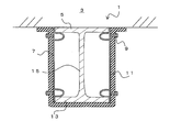
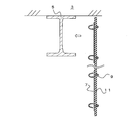
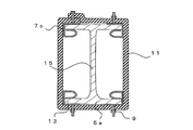
- FIG. 1A is a front view showing the fireproof structure 1 according to the first embodiment
- FIG. 1B is a sectional view taken along line AA of FIG. 1A.
- the fireproof structure 1 is a structure in which a beam 5 is coated with a fireproof covering material 11.
- the beam 5 is a so-called H-shaped steel in which a pair of flange portions 13 are connected by a web 15.
- the structure is not particularly limited as long as it has a flange portion 13, such as I-shaped steel, L-shaped steel, and angle steel.
- a floor 3 is installed on the upper part of the beam 5.
- a fixing bracket 7 for fixing the refractory covering material 11 to the beam 5 is fixed to the beam 5.
- the floor 3 is in contact with the beam 5, and a gap into which the fixing bracket 7 or the like can be inserted is not formed between the floor 3.
- the fixing bracket 7 has a main body portion 17 and spring portions 19 provided in the vicinity of both ends of the main body portion 17, respectively.
- the spring portion 19 is a portion for fixing the fixing bracket 7 to the flange portion 13 of the beam 5.
- the protrusion 21 projects toward the outer surface of the main body 17 (the surface opposite to the spring 19). That is, the fixing bracket 7 has a protrusion protruding outward.
- the protrusions 21 are arranged in the vicinity of both ends of the main body 17 and at substantially the same positions as the positions of the springs 19.
- the spring portion 19 and the protrusion portion 21 are joined to the plate-shaped main body portion 17 by, for example, welding.
- the protrusion 21 is, for example, pin-shaped and more preferably a male screw so that it can be pierced into the refractory coating material as described later.
- the material of the fixing bracket 7 is not particularly limited, but for example, an iron plate, a galvanized steel plate, a stainless steel plate, or the like can be applied, and in consideration of springiness, a stainless steel plate for spring is particularly suitable.
- protrusions 21 are not limited to the illustrated example.
- the protrusion 21 may be further arranged substantially in the center of the main body 17 in the longitudinal direction.
- shape of the spring portion 19 is not limited to the illustrated example, and is not particularly limited as long as the effect of the present embodiment can be obtained.
- the fixing bracket 7 is arranged between the pair of flange portions 13 formed on the beam 5.
- the distance between both ends of the pair of spring portions 19 is slightly larger than the distance between the flange portions 13. Therefore, the fixing bracket 7 is inserted between the flange portions 13 while the spring portion 19 is elastically deformed. In this way, each of the spring portions 19 has a restoring force toward the outside, and the fixing bracket 7 is fixed to the beam 5 by being pressed toward the inner surface side of the flange portion 13.
- the fixing brackets 7 are arranged on both sides of the beam 5. Further, the fixing metal fittings 7 are arranged at predetermined intervals with respect to the longitudinal direction of the beam 5. For example, the fixing brackets 7 are arranged at intervals according to the width of the refractory covering material 11.
- the refractory coating material 11 is fixed to the fixing bracket 7. At this time, the protrusion 21 is pierced into the fireproof coating material 11, so that the fireproof coating material 11 is fixed to the fixing bracket 7.
- the fireproof coating material 11 is a flexible member, and the beam 5 is covered with the fireproof coating material 11 by fixing the fireproof coating material 11 in a state of being wound around the beam 5.
- the fireproof coating material 11 is preferably a sheet-like member containing, for example, a thermal expansion material.
- the refractory coating material 11 is preferably made of a resin as a base material, not by an inorganic fiber such as rock wool as a main component. That is, it is desirable that the refractory coating material 11 is composed of a resin as a base material containing a thermal expansion material.
- the resin is not particularly limited, but for example, a thermoplastic resin, a thermosetting resin, rubber, an elastomer, or the like can be applied.
- the thermal expansion material contained in the resin is not particularly limited, and examples thereof include layered inorganic substances and phosphorus compounds.
- the layered inorganic substance examples include vermiculite, carion, mica, and heat-expandable graphite, and heat-expandable graphite is particularly preferable.
- a glass frit, an inorganic filler, or the like may be added to the resin.
- the refractory coating material 11 may be a foam or a non-foam.
- the fireproof coating material 11 may be combined with other members.
- the other members are not particularly limited as long as the effects of the present embodiment are not impaired, but members exhibiting heat resistance and / or flame retardancy are preferable.
- Examples of the composite in which the fireproof coating material 11 and other members are combined include a composite in which the fireproof coating material 11 and a noncombustible sheet are bonded together, and examples of the noncombustible sheet include a metal sheet and an inorganic fiber sheet. ..
- the metal sheet a metal sheet made of stainless steel, aluminum, iron or the like can be used. By forming the complex with the metal sheet in this way, the fire resistance can be further improved.
- a composite material of the refractory coating material 11 and the inorganic fiber sheet can also be mentioned.
- the inorganic fiber sheet include a sheet made of glass fiber, cellulose fiber, ceramic wool fiber, rock wool fiber and the like, a non-woven fabric, a woven fabric and the like.
- the non-woven fabric and the woven fabric may be those in which a thin aluminum layer is laminated.
- One kind or two or more kinds of such non-combustible sheets can be used.
- the protrusion 21 is a male screw. Therefore, the fireproof coating material 11 can be reliably fixed to the fixing bracket 7 by piercing the fireproof coating material 11 with a male screw and tightening the nut 9 from the outer surface side of the fireproof coating material 11. If a so-called round speed nut (Rond Type Speed Nut) is used as the nut 9, it can be easily fixed only by inserting it into a male screw, which is more preferable.
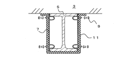
- the upper end portion of the fireproof coating material 11 may be arranged so as to abut against the lower surface of the floor 3, but as shown in FIG. 1B, the vicinity of the upper end portion of the fireproof coating material 11 may be arranged along the lower surface of the floor 3. It may be folded back. By doing so, the beam 5 can be more reliably covered with the fireproof coating material 11 without any gaps. Further, also in the longitudinal direction of the beam 5, the widthwise ends of the refractory covering materials 11 may be butted against each other, but they may be arranged so as to wrap each other. In this case, the protrusion 21 may be pierced into the overlapping portion of the refractory covering material 11 and fixed together.
- the construction method of the fireproof structure 1 for fixing the fireproof covering material 11 to the structure by using the fixing metal fitting 7 will be described.
- the fixing bracket 7 is inserted between the flange portions 13 of the beam 5 and fixed to the beam 5 by the spring portion 19.
- the protrusion 21 of the fixing bracket 7 is pierced into the fireproof coating material 11 to attach the fireproof coating material 11 to the fixing bracket 7.
- the refractory coating material 11 is pierced into the protrusion 21 of the fixing bracket 7 to fix the refractory coating material 11 to the beam 5, and the refractory coating material 11 is bent to cover the beam 5 over the entire circumference.
- the nut 9 is attached to the protrusion 21 (male screw) from the outer surface side of the refractory coating material 11. From the above, the fireproof structure 1 can be constructed.
- the construction method of the fireproof structure 1 is not limited to the above example.
- the protrusion 21 of the fixing bracket 7 may be pierced into a predetermined position of the fireproof coating material 11 to fix the fixing bracket 7 to the fireproof coating material 11.
- the refractory covering material 11 to which the fixing bracket 7 is fixed is transported to the installation site. Since the nut 9 is tightened to the protrusion 21 of the fixing bracket 7, the fireproof coating material 11 does not fall off from the protrusion 21 during transportation.
- the fixing bracket 7 fixed to the refractory covering material 11 is fixed to the beam 5 by the spring portion 19. Further, as shown in FIG. 4B, the refractory covering material 11 is wound around the beam 5 and the fixing bracket 7 is fixed to the beam 5, so that the refractory covering material 11 is fixed to the beam 5 to construct the fireproof structure 1. be able to.
- the fixing bracket 7 is fixed to the beam 5 by the spring portion 19, welding is not required and the fixing bracket 7 can be easily fixed to the beam 5. Further, the fireproof coating material 11 can be fixed to the fixing metal fitting 7 only by piercing the fireproof coating material 11 into the protrusion 21 of the fixing metal fitting 7. Therefore, the refractory covering material 11 can be easily fixed to the beam 5.
- the protrusion 21 is a male screw
- the nut 9 can surely prevent the refractory coating material 11 from falling off.
- the refractory coating material 11 is made of a resin containing a thermal expansion material, deterioration of the working environment is suppressed, and the work is easy because it is lightweight.
- resin as the base material it has excellent water resistance and can suppress deterioration during transportation compared to conventional rock wool and the like whose main component is inorganic fiber, so transportation work is easy. Is.
- the beam 5 is covered with the fireproof coating material 11 as a structure
- the protrusion 21 does not have to be a male screw, and may be, for example, a wire-shaped pin.
- the fireproof coating material 11 can be prevented from falling off by piercing the protrusion 21 into the fireproof coating material 11 and then bending the tip thereof.
- the fixing metal fitting 7 may fall off from the structure. Therefore, the main body 17 of the fixing bracket 7 may be reinforced.
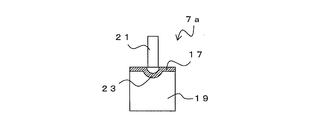
- FIG. 5A is a perspective view showing the fixing bracket 7a
- FIG. 5B is a sectional view taken along line BB of FIG. 5A.
- the fixing bracket 7a has substantially the same structure as the fixing bracket 7, but differs in that a reinforcing rib 23 is formed on the main body 17.
- a rib 23 is formed on the main body 17 so as to project toward the back surface along the longitudinal direction.
- the rib 23 is formed between the protrusions 21. Since the rib 23 increases the rigidity of the main body portion 17, it is possible to suppress the bending of the main body portion 17 due to the weight of the refractory covering material 11 or the like.
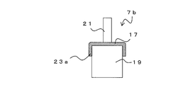
- the shape of the rib is not limited to the example shown in FIG. 6A is a perspective view showing the fixing bracket 7b, and FIG. 6B is a sectional view taken along line CC of FIG. 6A.
- the fixing bracket 7b has substantially the same structure as the fixing bracket 7a, but differs in that the rib 23a is formed.
- both ends of the main body 17 in the width direction are bent toward the back surface to form ribs 23a. That is, the main body portion 17 is formed in a substantially U shape in a cross section perpendicular to the longitudinal direction. Since the rib 23a increases the rigidity of the main body portion 17, it is possible to suppress the bending of the main body portion 17 due to the weight of the refractory covering material 11 or the like.
- FIG. 7 is a perspective view showing the fixing bracket 7d.
- the fixing bracket 7d has substantially the same structure as the fixing bracket 7b, except that the main body portion 17 and the spring portion 19 are formed of a single plate-shaped material.
- a pair of spring portions 19 are formed on both sides in the width direction in the vicinity of the respective ends, and a part of the main body portion 17 protrudes toward the end portion between the spring portions 19, and the protrusion portion 21 is formed at the portion. Is formed.
- both sides of the main body 17 in the width direction are bent to function as ribs 23b. By doing so, it functions in the same manner as the fixing bracket 7b and the like, and the fixing bracket 7d can be easily manufactured.
- FIG. 8A is an upward perspective view showing the fixing bracket 7e
- FIG. 8B is a downward perspective view showing the fixing bracket 7e.
- the fixing bracket 7e has substantially the same structure as the fixing bracket 7a and the like, but differs in that the plate-shaped member forming the spring portion 19 and the plate-shaped member having the protrusion 21 are joined by the rivet 25.
- the rib 23c may be formed on either one of the plate-shaped member forming the spring portion 19 and the plate-shaped member having the protrusion 21.
- jagged teeth may be formed at the tip of the spring portion 19. By doing so, the tip of the spring portion 19 can be easily bitten into another member. Such teeth are also applicable to other fixing brackets.
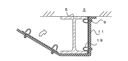
- FIG. 9A is a diagram showing a fireproof structure 1a
- FIG. 9B is a sectional view taken along line DD of FIG. 9A.
- the same components as those of the fireproof structure 1 and the like are designated by the same reference numerals as those in FIGS. 1 to 8, and duplicated description will be omitted.
- the pillar 5a which is a structure, is covered with the fireproof coating material 11. At this time, the refractory covering material 11 is fixed to the pillar 5a by the fixing metal fitting 7c.
- FIG. 10 is a perspective view of the fixing bracket 7c.
- the fixing bracket 7c is formed with a spring portion 19 for fixing to the flange portion 13 of the structure.
- the spring portion 19 is formed so as to face the main body portion 17.
- the protrusion 21 protrudes to the outside of the main body 17. More specifically, the plate-shaped main body 17 is bent in the direction opposite to the protruding direction of the protrusion 21, and the spring portion 19 is formed so as to face the back surface side of the protrusion 21.
- Fixing brackets 7c are fixed to both ends of each flange portion 13 of the pillar 5a. That is, the fixing metal fittings 7c are arranged at four places at substantially the same height as the pillars 5a.
- the refractory covering material 11 is wound around the pillar 5a. At this time, the fireproof coating material 11 is fixed to the pillar 5a by piercing the protrusion 21 into the fireproof coating material 11. Although the ends of the refractory covering material 11 may be butted against each other, it is desirable to wrap the ends with each other. At this time, in the wrap portion, the protrusion 21 may be passed through the two refractory covering materials 11 and fixed together.
- the fireproof structure 1a can also be constructed by the same method as the fireproof structure 1. That is, the fixing metal fitting 7c can be fixed to the pillar 5a at a predetermined position, and the refractory covering material 11 can be pierced into the protrusion 21 of the fixed fixing metal fitting 7c and wound around the pillar 5a to be fixed. Even in this case, the fireproof coating material 11 can be securely fixed by the nut 9 after the fireproof coating material 11 has been wound.
- the protrusion 21 of the fixing bracket 7c may be pierced and fixed in advance at a predetermined position of the fireproof coating material 11.
- the fixing bracket 7c can be fixed to the refractory coating material 11 in advance by the nut 9.
- the fireproof covering material 11 can be easily fixed to the pillar 5a by winding the fixing metal fitting 7c around the pillar 5a while attaching the fixing metal fitting 7c to the pillar 5a. can.
- the same effect as that of the first embodiment can be obtained. Further, the fixing bracket 7c can be used regardless of the distance between the flange portions 13.
Landscapes
- Engineering & Computer Science (AREA)
- Architecture (AREA)
- Physics & Mathematics (AREA)
- Electromagnetism (AREA)
- Civil Engineering (AREA)
- Structural Engineering (AREA)
- Building Environments (AREA)
Abstract
耐火構造1は、構造体である梁5に対して耐火被覆材11が被覆されたものである。固定金具7は、梁5に形成された一対のフランジ部13間に配置される。固定金具17には、耐火被覆材11が固定される。この際、固定金具7の突起部が耐火被覆材11に突き刺さることで、耐火被覆材11が固定金具7に固定される。耐火被覆材11は、可撓性を有する部材であり、耐火被覆材11を梁5に巻き付けた状態で固定することで、梁5が耐火被覆材11によって被覆される。
Description
本発明は、梁や柱などの構造体に耐火被覆材が被覆された耐火構造等に関するものである。
梁や柱などの鋼製の構造体は、火災等により高温となると耐力が低下するため、これを避けるために、耐火構造が必要である。
このような耐火構造としては、例えば、所定の厚みのロックウール等の耐火材を吹き付けて被覆する方法がある(例えば特許文献1)。特許文献1では、鉄骨梁に耐火材が吹き付けられて覆われる。
鉄骨に耐火材を吹き付ける方法は、安価であり、大型の構造体にも適用が容易であるが、作業環境が著しく悪く、吹き付け耐火材の吹き付け厚みや密度を管理することも困難である。また、吸水によって性能が劣化するため、事前に工場で鉄骨に吹き付け施工してから運搬するのも困難である。
これに対し、ロックウールを鉄骨に巻き付けて、その状態でピンを鉄骨に溶接することでロックウールを固定する方法も提案されている。しかし、この方法では、ロックウールを固定するピンを鉄骨に溶接するために、特殊な工具が必要であり、汎用性が低い。また、現場での溶接作業が含まれるため、周囲に可燃物があると危険である。一方、ロックウールは、吸水によって性能が劣化するため、事前に工場で鉄骨にロックウールの巻き付けとピン溶接を行ってから運搬するのも困難である。
また、鉄骨の表面に下地材を接着し、ケイ酸カルシウム板を釘で固定する方法も提案されている。しかし、成形板を用いるため、取り扱い中に割れが生じるなど、施工性は必ずしも良くない。また、成形板は、鉄骨へ耐火部材を巻き付ける方法と比較して高価である。
また、鉄骨の表面に熱膨張性塗料を塗布する方法も提案されている。しかし、塗装する塗料の厚みの管理などが困難であるとともに、塗料自体が非常に高価である。このため、より安価で容易に施工が可能な方法が望まれている。
本発明は、このような問題に鑑みてなされたもので、作業性が良好であり、安価に施工することが可能である耐火構造等を提供することを目的とする。
前述した目的を達成するため、第1の発明は、構造体に耐火被覆材が被覆された耐火構造であって、フランジ部を有する構造体と、前記構造体に固定される固定金具と、前記固定金具に固定される耐火被覆材とを具備し、前記固定金具は、前記構造体の前記フランジ部へ固定するためのばね部と、前記固定金具の外側に突出する突起部とを有し、前記突起部が、前記耐火被覆材に突き刺さることで、前記耐火被覆材が前記固定金具に固定され、可撓性を有する前記耐火被覆材によって前記構造体が被覆されることを特徴とする耐火構造である。
前記突起部は、雄ねじであり、前記雄ねじを前記耐火被覆材に突き刺して、前記耐火被覆材の外面側からナットによって固定されてもよい。
前記耐火被覆材は、ベース材である樹脂に熱膨張材が含まれて構成されていることが望ましい。
前記固定金具は、本体部の両端部近傍に前記ばね部をそれぞれ有し、前記固定金具が、前記構造体に形成された一対のフランジ部間に配置され、前記ばね部が前記フランジ部の内面側にそれぞれ押圧されることで、前記固定金具が前記構造体に固定され、前記突起部が、前記本体部の外面に向けて突出してもよい。
この場合、前記本体部には、補強用のリブが形成されてもよい。
また、前記ばね部は、前記固定金具の本体部と対向するように形成され、前記本体部と前記ばね部とで前記構造体の前記フランジ部を挟み込むことで、前記固定金具が前記構造体に固定され、前記突起部が、前記本体部の外面に向けて突出してもよい。
第1の発明によれば、ばね部を用いて固定金具を構造体に固定するため、固定作業が容易である。また、固定金具の突起部に耐火被覆材を突き刺すことで、耐火被覆材を固定金具に固定することができるため、溶接作業が不要であり、特殊な工具を使用することなく、耐火被覆材を構造体に容易に固定することができる。
また、突起部が雄ねじであれば、突き刺した後にナットを締めこむことで、確実に耐火被覆材を固定金具に固定することができる。
また、耐火被覆材が、ベース材である樹脂に熱膨張材が含まれて構成されていれば、厚みの薄い耐火被覆材を用いることができるため、作業も容易であるとともに、耐水性があるため、運搬も容易である。
また、固定金具の本体部の両端部近傍にばね部がそれぞれ配置されることで、H鋼の一対のフランジ部間に固定金具を配置した際に、ばね部の押し広がろうとする弾性力によって、フランジ部間に固定金具を固定することができる。このため、例えば上部に床が接触し、梁と床との間に隙間がないような場合でも、固定金具を梁に固定することができる。
また、この場合には、本体部にリブを形成することで、本体部のたわみが抑制され、固定金具の脱落を抑制することができる。
また、固定金具の本体部とばね部とが対向するように形成することで、構造体のフランジ部を本体部とばね部とで挟み込むことができる。このため、容易に固定金具を構造体に固定することができる。
第2の発明は、固定金具を用いて耐火被覆材を構造体に固定する耐火構造の施工方法であって、前記固定金具は、前記構造体のフランジ部へ固定するためのばね部と、前記固定金具の外側に突出する突起部とを有し、前記固定金具を前記構造体に前記ばね部によって固定し、前記突起部を前記耐火被覆材に突き刺して前記耐火被覆材を前記構造体に固定しつつ、前記耐火被覆材で前記構造体を被覆することを特徴とする耐火構造の施工方法である。
第2の発明によれば、現場にて容易に構造体に固定金具を取り付けることができるため、作業が容易である。
第3の発明は、固定金具を用いて耐火被覆材を構造体に固定する耐火構造の施工方法であって、前記固定金具は、前記構造体のフランジ部へ固定するためのばね部と、前記固定金具の外側に突出する突起部とを有し、前記突起部を前記耐火被覆材の所定位置に突き刺して、前記耐火被覆材に前記固定金具を固定し、前記ばね部によって、前記耐火被覆材に固定された前記固定金具を前記構造体に固定することで、前記耐火被覆材を前記構造体に巻き付けて固定することを特徴とする耐火構造の施工方法である。
第3の発明によれば、例えば工場等において、あらかじめ耐火被覆材の固定金具を固定しておくことができるため、現場での作業を削減し、作業を短縮することができる。
なお、第2、第3の発明において、前記突起部は、雄ねじであり、前記雄ねじを前記耐火被覆材に突き刺して、前記耐火被覆材の外面側からナットによって固定されてもよい。
第4の発明は、耐火被覆材を構造体に固定するための固定金具であって、本体部と、前記本体部の両端部近傍に形成され、構造体のフランジ部へ固定するためのばね部と、前記本体部の外側に突出する雄ねじ部と、を有し、前記固定金具を構造体に形成された一対のフランジ部間に配置した際に、前記ばね部が前記フランジ部の内面側にそれぞれ押圧されることで、前記固定金具を構造体に固定することが可能であることを特徴とする固定金具である。
また、第4の発明は、耐火被覆材を構造体に固定するための固定金具であって、本体部と、前記本体部に対向するように形成され、構造体のフランジ部へ固定するためのばね部と、前記本体部の外側に突出する雄ねじ部と、を有し、前記本体部と前記ばね部とで前記フランジ部を挟み込むことで、前記固定金具を構造体に固定することが可能であってもよい。
第4の発明によれば、ばね力によって固定金具を構造体に固定することができるため、溶接作業等が不要であり、作業も容易である。
本発明によれば、作業性が良好であり、安価に施工することが可能である耐火構造等を提供することができる。
(第1の実施形態)
以下、本発明の実施の形態について説明する。図1Aは、第1の実施形態にかかる耐火構造1を示す正面図、図1Bは、図1AのA-A線断面図である。耐火構造1は、構造体である梁5に対して耐火被覆材11が被覆されたものである。
以下、本発明の実施の形態について説明する。図1Aは、第1の実施形態にかかる耐火構造1を示す正面図、図1Bは、図1AのA-A線断面図である。耐火構造1は、構造体である梁5に対して耐火被覆材11が被覆されたものである。
梁5は、一対のフランジ部13がウェブ15によって連結された、いわゆるH形鋼である。なお、構造体としては、フランジ部13を有するものであれば、I形鋼、L字形鋼、山形鋼など特に限定されない。梁5の上部には、床3が設置される。梁5には、耐火被覆材11を梁5に固定するための固定金具7が固定される。なお、床3は梁5と接触し、両者の間には固定金具7等を挿入可能な隙間は形成されない。
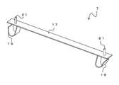
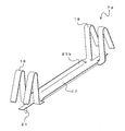
図2は、固定金具7は、本体部17と、本体部17の両端部近傍にそれぞれ設けられたばね部19を有する。ばね部19は、固定金具7を梁5のフランジ部13へ固定するための部位である。本体部17の外面(ばね部19とは逆側の面)に向けて突起部21が突出する。すなわち、固定金具7は、外側に突出する突起部を有する。突起部21は、本体部17の両端部近傍であって、ばね部19の位置と略同様の位置に配置される。固定金具7は、板状の本体部17に対して、ばね部19と突起部21が、例えば溶接等で接合される。突起部21は、後述するように耐火被覆材に突き刺さることができるよう、例えばピン状であり、雄ねじであることがより好ましい。
なお、固定金具7の材質としては、特に限定されないが、例えば、鉄板や亜鉛メッキ鋼板やステンレス鋼板などを適用可能であり、ばね性を考慮すると、特に、ばね用ステンレス鋼板が適している。
なお、突起部21の配置される位置や個数は図示した例には限られない。例えば、本体部17の長手方向の略中央に、突起部21をさらに配置してもよい。また、ばね部19の形状は、図示した例には限られず、本実施形態の効果を得ることが可能な形態であれば特に限定されない。
図1Bに示すように、固定金具7は、梁5に形成された一対のフランジ部13間に配置される。この際、一対のばね部19の両端部間の距離は、フランジ部13同士の間の距離もよりもわずかに大きい。このため、固定金具7は、ばね部19が弾性変形しながらフランジ部13間に挿入される。このように、ばね部19は、それぞれ外側に向けた復元力を有し、フランジ部13の内面側にそれぞれ押圧されることで、固定金具7が梁5に固定される。
固定金具7は、梁5の両側にそれぞれ配置される。また、固定金具7は、梁5の長手方向に対して、所定の間隔で配置される。例えば、耐火被覆材11の幅に応じた間隔で固定金具7が配置される。
固定金具7には、耐火被覆材11が固定される。この際、突起部21が耐火被覆材11に突き刺さることで、耐火被覆材11が固定金具7に固定される。耐火被覆材11は、可撓性を有する部材であり、耐火被覆材11を梁5に巻き付けた状態で固定することで、梁5が耐火被覆材11によって被覆される。
なお、耐火被覆材11は、例えば熱膨張材が含まれるシート状の部材であることが望ましい。なお、耐火被覆材11は、取り扱い性を考慮すると、ロックウールなどの無機繊維を主成分とするものではなく、樹脂をベース材とするものが望ましい。すなわち、耐火被覆材11は、ベース材である樹脂に熱膨張材が含まれて構成されていることが望ましい。なお、樹脂としては、特に限定されないが、例えば、熱可塑性樹脂、熱硬化性樹脂、ゴム、エラストマー等を適用可能である。また、樹脂に含有させる熱膨張材としては、特に限定されないが、例えば、層状無機物、リン化合物が挙げられる。層状無機物としては、バーミキュライト、カリオン、マイカ、熱膨張性黒鉛などが挙げられ、特に熱膨張性黒鉛が好ましい。さらに、ガラスフリットや無機フィラー等を樹脂に配合してもよい。また、耐火被覆材11は、発泡体であってもよく、非発泡体であってもよい。
また、耐火被覆材11に、他の部材を組み合わせてもよい。他の部材としては、本実施形態の効果を損なわない限り特に限定されないが、耐熱性及び/又は難燃性を示す部材が好ましい。耐火被覆材11と他の部材とを組み合わせた複合体の例としては、耐火被覆材11と不燃シートとを貼合したものが挙げられ、不燃シートとしては、金属シートと無機繊維シートが挙げられる。金属シートとしては、ステンレス、アルミニウム、鉄などからなる金属シートを用いることができる。このように金属シートとの複合体とすることにより、耐火性能をより向上することができる。また他に、耐火被覆材11と無機繊維シートとの複合材も挙げられる。無機繊維シートとしては、例えば、ガラス繊維、セルロース繊維、セラミックウール繊維、ロックウール繊維等からなるシート、不織布、織布などが挙げられる。不織布、織布は、薄いアルミニウム層が積層されたものであってもよい。このような不燃シートは一種もしくは二種以上を使用することができる。
本実施形態では、突起部21は雄ねじである。したがって、雄ねじを耐火被覆材11に突き刺して、耐火被覆材11の外面側からナット9を締めこむことによって、確実に耐火被覆材11を固定金具7に固定することができる。なお、ナット9として、いわゆる丸形スピードナット(Round Type Speed Nut)と呼ばれるものを使用すれば、雄ねじへの差し込みのみで容易に固定が可能となり、より好ましい。
なお、耐火被覆材11の上端部を、床3の下面に突き合わせるように配置してもよいが、図1Bに示すように、耐火被覆材11の上端部近傍を床3の下面に沿って折り返してもよい。このようにすることで、より確実に梁5を隙間なく耐火被覆材11で被覆することができる。また、梁5の長手方向に対しても、耐火被覆材11の幅方向端部同士を突き合わせてもよいが、互いにラップするように配置してもよい。この場合、耐火被覆材11の重なり部分に突起部21を突き刺して一括して固定してもよい。
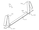
次に、固定金具7を用いて耐火被覆材11を構造体に固定する耐火構造1の施工方法について説明する。まず、図3Aに示すように、固定金具7を梁5のフランジ部13間に挿入し、ばね部19によって梁5に固定する。次に、図3Bに示すように、固定金具7の突起部21を耐火被覆材11に突き刺して耐火被覆材11を固定金具7に取り付ける。
このように、固定金具7の突起部21に耐火被覆材11を突き刺して耐火被覆材11を梁5に固定しつつ、耐火被覆材11を折り曲げて梁5を全周にわたって被覆する。最後に、図3Cに示すように、耐火被覆材11の外面側から突起部21(雄ねじ)にナット9を取りつける。以上により、耐火構造1を施工することができる。
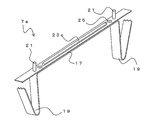
なお、耐火構造1の施工方法は上述した例には限られない。例えば、あらかじめ工場等において、固定金具7の突起部21を耐火被覆材11の所定位置に突き刺して、耐火被覆材11に固定金具7を固定しておいてもよい。固定金具7が固定された耐火被覆材11は設置現場に運搬される。なお、固定金具7の突起部21には、ナット9が締めこまれているため、運搬時に突起部21から耐火被覆材11が脱落することがない。
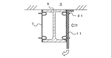
次に、図4Aに示すように、ばね部19によって、耐火被覆材11に固定された固定金具7を梁5に固定する。さらに、図4Bに示すように、耐火被覆材11を梁5に巻き付けて、固定金具7を梁5に固定することで、耐火被覆材11が梁5に固定されて、耐火構造1を構築することができる。
以上、第1の実施の形態によれば、固定金具7をばね部19によって梁5に固定するため、溶接も不要であり、容易に固定金具7を梁5へ固定することができる。また、固定金具7の突起部21へ耐火被覆材11を突き刺すだけで、耐火被覆材11を固定金具7に固定することができる。このため、耐火被覆材11を容易に梁5へ固定することができる。
また、突起部21が雄ねじであるため、ナット9によって、確実に耐火被覆材11の脱落を抑制することができる。また、耐火被覆材11は熱膨張材が含まれた樹脂製であるため、作業環境の悪化を抑制し、軽量であるため作業も容易である。また、ベース材として樹脂を適用することで、従来の無機繊維を主成分とするロックウール等と比較して、耐水性に優れ、運搬時の劣化等を抑制可能であるため、運搬作業も容易である。
なお、以上の説明では、構造体として梁5を耐火被覆材11で被覆した例を説明したが、柱に対しても適用可能である。また、突起部21は、雄ねじでなくてもよく、例えば、針金状のピンであってもよい。この場合には、耐火被覆材11に突起部21を突き刺して、その後先端を屈曲させることで、耐火被覆材11の脱落を抑制することができる。
なお、耐火被覆材11を固定した際に、本体部17の撓みが大きくなると、固定金具7が構造体から脱落するおそれがある。このため、固定金具7の本体部17を補強してもよい。
図5Aは、固定金具7aを示す斜視図であり、図5Bは、図5AのB-B線断面図である。固定金具7aは、固定金具7と略同様の構造であるが、本体部17に補強用のリブ23が形成される点で異なる。本体部17には、長手方向に沿って背面側に突出するリブ23が形成される。リブ23は、突起部21同士の間に形成される。リブ23によって、本体部17の剛性が高くなるため、耐火被覆材11の重み等による本体部17の撓みを抑制することができる。
また、リブの形態は図5に示した例には限られない。図6Aは、固定金具7bを示す斜視図であり、図6Bは、図6AのC-C線断面図である。固定金具7bは、固定金具7aと略同様の構造であるが、リブ23aが形成される点で異なる。固定金具7bは、本体部17の幅方向の両端部が背面側に屈曲してリブ23aが形成される。すなわち、本体部17は、長手方向に垂直な断面において、略コの字状に形成される。リブ23aによって、本体部17の剛性が高くなるため、耐火被覆材11の重み等による本体部17の撓みを抑制することができる。
また、本体部17とばね部19とを別体で形成して接合するのではなく、一体で形成してもよい。図7は、固定金具7dを示す斜視図である。固定金具7dは、固定金具7bと略同様の構造であるが、本体部17とばね部19が、一枚の板状の素材から形成される点で異なる。この場合、幅方向の両側に一対のばね部19がそれぞれの端部近傍に形成され、ばね部19同士の間において、本体部17の一部が端部側に突出し、当該部位に突起部21が形成される。また、本体部17の幅方向の両側は折り曲げられてリブ23bとして機能する。このようにすることで、固定金具7b等と同様に機能するとともに、固定金具7dの製造が容易である。
また、本体部17とばね部19とを別体で形成する場合には、ばね部19を形成する部材と、突起部21を形成する部材とを接合してもよい。図8Aは、固定金具7eを示す上方斜視図であり、図8Bは、固定金具7eを示す下方斜視図である。固定金具7eは、固定金具7a等と略同様の構造であるが、ばね部19を形成する板状部材と、突起部21を有する板状部材とが、リベット25で接合される点で異なる。この場合、ばね部19を形成する板状部材と、突起部21を有する板状部材のいずれか一方にリブ23cを形成すればよい。
なお、固定金具7d、7eに示すように、ばね部19の先端に、ぎざぎざの歯を形成してもよい。このようにすることで、ばね部19の先端を、他の部材に対して食い込みやすくすることができる。このような歯は、他の固定金具にも適用可能である。
(第2の実施形態)
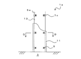
次に、第2の実施形態について説明する。図9Aは、耐火構造1aを示す図であり、図9Bは、図9AのD-D線断面図である。なお、以下の説明において、耐火構造1等と同様の構成には、図1~図8と同一の符号を付して、重複する説明を省略する。
次に、第2の実施形態について説明する。図9Aは、耐火構造1aを示す図であり、図9Bは、図9AのD-D線断面図である。なお、以下の説明において、耐火構造1等と同様の構成には、図1~図8と同一の符号を付して、重複する説明を省略する。
第2の実施形態にかかる耐火構造1aでは、構造体である柱5aが耐火被覆材11によって被覆される。この際、耐火被覆材11は、固定金具7cによって、柱5aに固定される。
図10は、固定金具7cの斜視図である。固定金具7cは、固定金具7等と同様に、構造体のフランジ部13へ固定するためのばね部19が形成される。ばね部19は、本体部17に対向するように形成される。また、突起部21が、本体部17の外側に突出する。より具体的には、板状の本体部17は、突起部21の突出方向とは逆方向に屈曲されて、突起部21の裏面側に対向するようにばね部19が形成される。
ばね部19と本体部17との間に柱5aのフランジ部13を挿入することで、ばね部19と本体部17とでフランジ部13が挟み込まれて、固定金具7cが柱5aに固定される。柱5aのそれぞれのフランジ部13の両端部に、固定金具7cが固定される。すなわち、固定金具7cは、柱5aの略同一高さにおいて、4か所に配置される。
耐火被覆材11は、柱5aに巻き付けられる。この際、突起部21を耐火被覆材11に突き刺すことで、耐火被覆材11が柱5aに固定される。なお、耐火被覆材11の端部同士を突き合わせてもよいが、端部同士をラップさせることが望ましい。この際、ラップ部においては、突起部21を2枚の耐火被覆材11を貫通させて、一括して固定してもよい。
なお、耐火構造1aも耐火構造1と同様の方法で施工することができる。すなわち、柱5aに対して、所定の位置に固定金具7cを固定し、固定された固定金具7cの突起部21に耐火被覆材11を突き刺しながら柱5aに巻きつけて固定することができる。なお、この場合でも、耐火被覆材11を巻き付け終えた後に、ナット9によって耐火被覆材11を確実に固定することができる。
また、あらかじめ耐火被覆材11の所定の位置に固定金具7cの突起部21を突き刺して固定しておいてもよい。この場合、あらかじめナット9によって固定金具7cを耐火被覆材11に固定することができる。このようにして固定金具7cが固定された耐火被覆材11を用いることで、固定金具7cを柱5aに取り付けながら柱5aに巻き付けることで、容易に耐火被覆材11を柱5aに固定することができる。
第2の実施形態によれば、第1の実施形態と同様の効果を得ることができる。また、固定金具7cは、フランジ部13同士の間隔によらず、使用することができる。
以上、添付図を参照しながら、本発明の実施の形態を説明したが、本発明の技術的範囲は、前述した実施の形態に左右されない。当業者であれば、特許請求の範囲に記載された技術的思想の範疇内において各種の変更例または修正例に想到し得ることは明らかであり、それらについても当然に本発明の技術的範囲に属するものと了解される。
1、1a………耐火構造
3………床
5………梁
5a………柱
7、7a、7b、7c………固定金具
9………ナット
11………耐火被覆材
13………フランジ部
15………ウェブ
17………本体部
19………ばね部
21………突起部
23、23a、23b、23c………リブ
25………リベット
3………床
5………梁
5a………柱
7、7a、7b、7c………固定金具
9………ナット
11………耐火被覆材
13………フランジ部
15………ウェブ
17………本体部
19………ばね部
21………突起部
23、23a、23b、23c………リブ
25………リベット
Claims (11)
- 構造体に耐火被覆材が被覆された耐火構造であって、
フランジ部を有する構造体と、
前記構造体に固定される固定金具と、
前記固定金具に固定される耐火被覆材と
を具備し、
前記固定金具は、前記構造体の前記フランジ部へ固定するためのばね部と、前記固定金具の外側に突出する突起部とを有し、
前記突起部が、前記耐火被覆材に突き刺さることで、前記耐火被覆材が前記固定金具に固定され、可撓性を有する前記耐火被覆材によって前記構造体が被覆されることを特徴とする耐火構造。 - 前記突起部は、雄ねじであり、前記雄ねじを前記耐火被覆材に突き刺して、前記耐火被覆材の外面側からナットによって固定されることを特徴とする請求項1記載の耐火構造。
- 前記耐火被覆材は、ベース材である樹脂に熱膨張材が含まれて構成されていることを特徴とする請求項1又は請求項2記載の耐火構造。
- 前記固定金具は、本体部の両端部近傍に前記ばね部をそれぞれ有し、前記固定金具が、前記構造体に形成された一対のフランジ部間に配置され、前記ばね部が前記フランジ部の内面側にそれぞれ押圧されることで、前記固定金具が前記構造体に固定され、
前記突起部が、前記本体部の外面に向けて突出することを特徴とする請求項1から請求項3のいずれかに記載の耐火構造。 - 前記本体部には、補強用のリブが形成されることを特徴とする請求項4に記載の耐火構造。
- 前記ばね部は、前記固定金具の本体部と対向するように形成され、前記本体部と前記ばね部とで前記構造体の前記フランジ部を挟み込むことで、前記固定金具が前記構造体に固定され、
前記突起部が、前記本体部の外面に向けて突出することを特徴とする請求項1から請求項3のいずれかに記載の耐火構造。 - 固定金具を用いて耐火被覆材を構造体に固定する耐火構造の施工方法であって、
前記固定金具は、前記構造体のフランジ部へ固定するためのばね部と、前記固定金具の外側に突出する突起部とを有し、
前記固定金具を前記構造体に前記ばね部によって固定し、前記突起部を前記耐火被覆材に突き刺して前記耐火被覆材を前記構造体に固定しつつ、前記耐火被覆材で前記構造体を被覆することを特徴とする耐火構造の施工方法。 - 固定金具を用いて耐火被覆材を構造体に固定する耐火構造の施工方法であって、
前記固定金具は、前記構造体のフランジ部へ固定するためのばね部と、前記固定金具の外側に突出する突起部とを有し、
前記突起部を前記耐火被覆材の所定位置に突き刺して、前記耐火被覆材に前記固定金具を固定し、
前記ばね部によって、前記耐火被覆材に固定された前記固定金具を前記構造体に固定することで、前記耐火被覆材を前記構造体に巻き付けて固定することを特徴とする耐火構造の施工方法。 - 前記突起部は、雄ねじであり、前記雄ねじを前記耐火被覆材に突き刺して、前記耐火被覆材の外面側からナットによって固定されることを特徴とする請求項7又は請求項8記載の耐火構造の施工方法。
- 耐火被覆材を構造体に固定するための固定金具であって、
本体部と、
前記本体部の両端部近傍に形成され、構造体のフランジ部へ固定するためのばね部と、
前記本体部の外側に突出する雄ねじ部と、を有し、
前記固定金具を構造体に形成された一対のフランジ部間に配置した際に、前記ばね部が前記フランジ部の内面側にそれぞれ押圧されることで、前記固定金具を構造体に固定することが可能であることを特徴とする固定金具。 - 耐火被覆材を構造体に固定するための固定金具であって、
本体部と、
前記本体部に対向するように形成され、構造体のフランジ部へ固定するためのばね部と、
前記本体部の外側に突出する雄ねじ部と、を有し、
前記本体部と前記ばね部とで前記フランジ部を挟み込むことで、前記固定金具を構造体に固定することが可能であることを特徴とする固定金具。
Priority Applications (1)
| Application Number | Priority Date | Filing Date | Title |
|---|---|---|---|
| JP2021557572A JPWO2022004591A1 (ja) | 2020-06-30 | 2021-06-25 |
Applications Claiming Priority (2)
| Application Number | Priority Date | Filing Date | Title |
|---|---|---|---|
| JP2020-113278 | 2020-06-30 | ||
| JP2020113278 | 2020-06-30 |
Publications (1)
| Publication Number | Publication Date |
|---|---|
| WO2022004591A1 true WO2022004591A1 (ja) | 2022-01-06 |
Family
ID=79316284
Family Applications (1)
| Application Number | Title | Priority Date | Filing Date |
|---|---|---|---|
| PCT/JP2021/024137 WO2022004591A1 (ja) | 2020-06-30 | 2021-06-25 | 耐火構造、耐火構造の施工方法及び固定金具 |
Country Status (2)
| Country | Link |
|---|---|
| JP (1) | JPWO2022004591A1 (ja) |
| WO (1) | WO2022004591A1 (ja) |
Citations (6)
| Publication number | Priority date | Publication date | Assignee | Title |
|---|---|---|---|---|
| JPH0740823U (ja) * | 1993-12-28 | 1995-07-21 | 順三 白鳥 | 耐火・防火用断熱材の取付金具 |
| JPH07189359A (ja) * | 1993-12-27 | 1995-07-28 | Ask:Kk | 鉄骨耐火被覆構造および鉄骨耐火被覆工法 |
| JPH086892Y2 (ja) * | 1989-12-07 | 1996-02-28 | 株式会社フジタ | 鉄骨梁への耐火被覆材取付構造 |
| JP2672512B2 (ja) * | 1987-08-05 | 1997-11-05 | 株式会社 三和クリ−ン | 被覆材取付用スペーサ |
| JP3103925B2 (ja) * | 1991-03-04 | 2000-10-30 | 積水ハウス株式会社 | 耐火被覆材の取付装置 |
| JP2013234459A (ja) * | 2012-05-07 | 2013-11-21 | Sekisui Chem Co Ltd | 鉄骨の耐火被覆構造 |
-
2021
- 2021-06-25 JP JP2021557572A patent/JPWO2022004591A1/ja active Pending
- 2021-06-25 WO PCT/JP2021/024137 patent/WO2022004591A1/ja active Application Filing
Patent Citations (6)
| Publication number | Priority date | Publication date | Assignee | Title |
|---|---|---|---|---|
| JP2672512B2 (ja) * | 1987-08-05 | 1997-11-05 | 株式会社 三和クリ−ン | 被覆材取付用スペーサ |
| JPH086892Y2 (ja) * | 1989-12-07 | 1996-02-28 | 株式会社フジタ | 鉄骨梁への耐火被覆材取付構造 |
| JP3103925B2 (ja) * | 1991-03-04 | 2000-10-30 | 積水ハウス株式会社 | 耐火被覆材の取付装置 |
| JPH07189359A (ja) * | 1993-12-27 | 1995-07-28 | Ask:Kk | 鉄骨耐火被覆構造および鉄骨耐火被覆工法 |
| JPH0740823U (ja) * | 1993-12-28 | 1995-07-21 | 順三 白鳥 | 耐火・防火用断熱材の取付金具 |
| JP2013234459A (ja) * | 2012-05-07 | 2013-11-21 | Sekisui Chem Co Ltd | 鉄骨の耐火被覆構造 |
Also Published As
| Publication number | Publication date |
|---|---|
| JPWO2022004591A1 (ja) | 2022-01-06 |
Similar Documents
| Publication | Publication Date | Title |
|---|---|---|
| KR100538079B1 (ko) | 벽구조 | |
| WO2022004591A1 (ja) | 耐火構造、耐火構造の施工方法及び固定金具 | |
| JP2009047193A (ja) | ダンパー装置および構造物 | |
| JP2002061339A (ja) | 耐火断熱屋根構造 | |
| JP4545924B2 (ja) | 耐火建物構造 | |
| JP2023053831A (ja) | 耐火被覆材用固定金具、耐火構造および耐火構造の施工方法 | |
| JP7488236B2 (ja) | 耐火被覆材用固定金具、耐火構造および耐火構造の施工方法 | |
| JP2017089266A (ja) | 鋼製耐震壁の耐火構造 | |
| JP2013079553A (ja) | コンクリート充填鋼管柱の耐火補強構造 | |
| JP7488237B2 (ja) | 耐火被覆材用固定金具、耐火構造および耐火構造の施工方法 | |
| JP6508289B2 (ja) | 鉄骨柱の合成被覆耐火構造の施工方法 | |
| JP3116064B2 (ja) | 建築用外装材及び建築用外装材を使用した建築用外装パネル | |
| RU2767836C1 (ru) | Строительная система и способ возведения здания | |
| JP6778136B2 (ja) | 溝形鋼の耐火被覆構造 | |
| JP2921366B2 (ja) | 金属複合屋根材及びその施工方法 | |
| JP5814590B2 (ja) | 建築用パネルの接続構造 | |
| JPH11280203A (ja) | スチ−ルハウスの組立構造及び組立ユニット | |
| JP7197926B2 (ja) | 耐火被覆方法、鉄骨梁及び耐火被覆材 | |
| CN218522115U (zh) | 一种连接龙骨及其防火墙板结构 | |
| KR102476088B1 (ko) | 내화 패널의 보강재 및 이 보강재를 사용한 내화 패널 | |
| JP4559793B2 (ja) | 連層耐震壁 | |
| JP4058861B2 (ja) | 鉄骨躯体の耐火被覆構造および被覆用耐火パネルの取付け金具 | |
| JP7197925B2 (ja) | 耐火被覆方法及び鉄骨梁 | |
| JP7464368B2 (ja) | 断熱材の施工構造及び断熱材の施工方法 | |
| JP7256497B2 (ja) | 吸音材保持構造およびその構築方法 |
Legal Events
| Date | Code | Title | Description |
|---|---|---|---|
| ENP | Entry into the national phase |
Ref document number: 2021557572 Country of ref document: JP Kind code of ref document: A |
|
| 121 | Ep: the epo has been informed by wipo that ep was designated in this application |
Ref document number: 21834283 Country of ref document: EP Kind code of ref document: A1 |
|
| NENP | Non-entry into the national phase |
Ref country code: DE |
|
| 122 | Ep: pct application non-entry in european phase |
Ref document number: 21834283 Country of ref document: EP Kind code of ref document: A1 |