WO2022003797A1 - 空調機、制御装置、空調システム及び空調方法 - Google Patents
空調機、制御装置、空調システム及び空調方法 Download PDFInfo
- Publication number
- WO2022003797A1 WO2022003797A1 PCT/JP2020/025588 JP2020025588W WO2022003797A1 WO 2022003797 A1 WO2022003797 A1 WO 2022003797A1 JP 2020025588 W JP2020025588 W JP 2020025588W WO 2022003797 A1 WO2022003797 A1 WO 2022003797A1
- Authority
- WO
- WIPO (PCT)
- Prior art keywords
- required time
- time
- temperature
- room
- air conditioner
- Prior art date
- Legal status (The legal status is an assumption and is not a legal conclusion. Google has not performed a legal analysis and makes no representation as to the accuracy of the status listed.)
- Ceased
Links
Images









Classifications
-
- F—MECHANICAL ENGINEERING; LIGHTING; HEATING; WEAPONS; BLASTING
- F24—HEATING; RANGES; VENTILATING
- F24F—AIR-CONDITIONING; AIR-HUMIDIFICATION; VENTILATION; USE OF AIR CURRENTS FOR SCREENING
- F24F11/00—Control or safety arrangements
- F24F11/30—Control or safety arrangements for purposes related to the operation of the system, e.g. for safety or monitoring
- F24F11/48—Control or safety arrangements for purposes related to the operation of the system, e.g. for safety or monitoring prior to normal operation, e.g. pre-heating or pre-cooling
-
- F—MECHANICAL ENGINEERING; LIGHTING; HEATING; WEAPONS; BLASTING
- F24—HEATING; RANGES; VENTILATING
- F24F—AIR-CONDITIONING; AIR-HUMIDIFICATION; VENTILATION; USE OF AIR CURRENTS FOR SCREENING
- F24F11/00—Control or safety arrangements
- F24F11/50—Control or safety arrangements characterised by user interfaces or communication
- F24F11/61—Control or safety arrangements characterised by user interfaces or communication using timers
-
- F—MECHANICAL ENGINEERING; LIGHTING; HEATING; WEAPONS; BLASTING
- F24—HEATING; RANGES; VENTILATING
- F24F—AIR-CONDITIONING; AIR-HUMIDIFICATION; VENTILATION; USE OF AIR CURRENTS FOR SCREENING
- F24F11/00—Control or safety arrangements
- F24F11/50—Control or safety arrangements characterised by user interfaces or communication
- F24F11/56—Remote control
- F24F11/58—Remote control using Internet communication
-
- F—MECHANICAL ENGINEERING; LIGHTING; HEATING; WEAPONS; BLASTING
- F24—HEATING; RANGES; VENTILATING
- F24F—AIR-CONDITIONING; AIR-HUMIDIFICATION; VENTILATION; USE OF AIR CURRENTS FOR SCREENING
- F24F11/00—Control or safety arrangements
- F24F11/62—Control or safety arrangements characterised by the type of control or by internal processing, e.g. using fuzzy logic, adaptive control or estimation of values
- F24F11/63—Electronic processing
- F24F11/64—Electronic processing using pre-stored data
-
- F—MECHANICAL ENGINEERING; LIGHTING; HEATING; WEAPONS; BLASTING
- F24—HEATING; RANGES; VENTILATING
- F24F—AIR-CONDITIONING; AIR-HUMIDIFICATION; VENTILATION; USE OF AIR CURRENTS FOR SCREENING
- F24F11/00—Control or safety arrangements
- F24F11/30—Control or safety arrangements for purposes related to the operation of the system, e.g. for safety or monitoring
- F24F11/46—Improving electric energy efficiency or saving
-
- F—MECHANICAL ENGINEERING; LIGHTING; HEATING; WEAPONS; BLASTING
- F24—HEATING; RANGES; VENTILATING
- F24F—AIR-CONDITIONING; AIR-HUMIDIFICATION; VENTILATION; USE OF AIR CURRENTS FOR SCREENING
- F24F2110/00—Control inputs relating to air properties
- F24F2110/10—Temperature
-
- F—MECHANICAL ENGINEERING; LIGHTING; HEATING; WEAPONS; BLASTING
- F24—HEATING; RANGES; VENTILATING
- F24F—AIR-CONDITIONING; AIR-HUMIDIFICATION; VENTILATION; USE OF AIR CURRENTS FOR SCREENING
- F24F2110/00—Control inputs relating to air properties
- F24F2110/10—Temperature
- F24F2110/12—Temperature of the outside air
-
- F—MECHANICAL ENGINEERING; LIGHTING; HEATING; WEAPONS; BLASTING
- F24—HEATING; RANGES; VENTILATING
- F24F—AIR-CONDITIONING; AIR-HUMIDIFICATION; VENTILATION; USE OF AIR CURRENTS FOR SCREENING
- F24F2120/00—Control inputs relating to users or occupants
- F24F2120/10—Occupancy
- F24F2120/14—Activity of occupants
Definitions
- This disclosure relates to air conditioners, control devices, air conditioning systems and air conditioning methods.
- Patent Document 1 A technique for controlling an air conditioner installed in a house so that a user arriving at home can obtain a desired temperature is known (for example, Patent Document 1).
- the navigation device acquires the outside air temperature from the outside air temperature sensor provided in the vehicle, and is the operating time of the air conditioner required for temperature adjustment from the acquired outside air temperature to the user's desired temperature. Get the required operating time.
- the navigation device calculates the time required to arrive at home and sends an operation start command to the air conditioner when the time required for arrival approaches the required operating time.
- the navigation device stores in advance an adjustment time table in which the initial temperature, the target temperature, and the adjustment time of the air conditioner are associated with each other, and prepares the adjustment time table from the outside air temperature and the desired temperature. Refer to directly to get the required operating time of the air conditioner.
- This disclosure is made to solve the above problem, and it is automatically performed at an appropriate timing by accurately acquiring the time required from the start of air conditioning of the room to the time when the room temperature reaches the target temperature.
- the purpose is to provide an air conditioner or the like capable of starting operation.
- the air conditioner according to this disclosure is An arrival time acquisition method for acquiring the arrival time required for the user to arrive at the building, and an arrival time acquisition method.
- the first from the start of air conditioning of a room in the building until the room temperature reaches the target intermediate temperature, which is the temperature reached before reaching the target temperature and is determined based on the set temperature of the room.
- the first means for acquiring the required time and the method for acquiring the required time A second required time acquisition means for acquiring a second required time from the start of air conditioning in the room until the room temperature reaches the target temperature based on the acquired first required time.
- the operation control means for starting the air conditioning operation when the acquired arrival required time is within the acquired second required time is provided.
- Block diagram showing the hardware configuration of the air conditioner in the embodiment A block diagram showing a hardware configuration of a terminal device according to an embodiment.
- Block diagram showing the hardware configuration of the cloud server in the embodiment Block diagram showing the functional configuration of the air conditioner and the cloud server in the embodiment
- the figure which shows the example of the transition of the room temperature after the air conditioner in an Embodiment starts a heating operation.
- the figure which shows the example of the transition of the air conditioning capacity after the air conditioner in an embodiment starts a heating operation.
- the figure which shows the example of the transition of the room temperature after the air conditioner of an embodiment starts a heating operation by the size of the heat capacity of a room.
- FIG. 1 is a diagram showing the overall configuration of the air conditioning system 1 according to the embodiment of the present disclosure.
- the air-conditioning system 1 is a system for air-conditioning the house H, and includes an air conditioner 2, a terminal device 3, and a cloud server 4.
- the air conditioner 2 is a heat pump type air conditioner that uses HFC (hydrofluorocarbon) such as R32 and a natural refrigerant such as CO 2 as a refrigerant, and air-conditions the room in the house H.
- the air conditioner 2 is equipped with a steam compression type refrigeration cycle, and operates by obtaining electric power from a commercial power source, a power generation facility, a power storage facility, etc. (not shown).
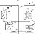
- the air conditioner 2 includes an indoor unit 20 installed in the room R and an outdoor unit 21 installed outdoors.
- the indoor unit 20 and the outdoor unit 21 are connected to each other via a refrigerant pipe 22 for circulating the refrigerant and a communication line 23.
- the indoor unit 20 includes a control circuit 200, a heat exchanger 201, a fan 202, a temperature sensor 203, a humidity sensor 204, a thermal image sensor 205, and a communication interface 206.
- the control circuit 200 comprehensively controls the air conditioner 2.
- the control circuit 200 includes a CPU (Central Processing Unit), a ROM (ReadOnlyMemory), a RAM (RandomAccessMemory), a communication interface, and an EEPROM (Electrically ErasableProgrammableRead-OnlyMemory). It includes an auxiliary storage device including a readable / writable non-volatile semiconductor memory such as a flash memory. The details of the function of the air conditioner 2 realized by the control circuit 200 will be described later.
- the heat exchanger 201 exchanges heat between the indoor air sucked by the fan 202 (that is, the air in the room R) and the refrigerant from the outdoor unit 21.
- the heat exchanger 201 functions as an evaporator during the cooling operation and as a condenser during the heating operation.
- the fan 202 is, for example, a propeller fan and sucks in the air in the room from a suction port (not shown) and sends out the air heat exchanged by the heat exchanger 201 into the room from the outlet (see FIG. 2).
- the rotation speed of the fan 202 that is, the amount of air blown by the fan 202 is adjusted according to a command from the control circuit 200.
- the temperature sensor 203 is a sensor such as a thermistor, a thermocouple, and a resistance temperature detector, measures the temperature of the air sucked by the fan 202, and outputs a signal indicating the measurement result to the control circuit 200.
- the humidity sensor 204 is an electric resistance type sensor, a capacitance type sensor, or the like, measures the humidity of the air sucked by the fan 202, and outputs a signal indicating the measurement result to the control circuit 200.
- the thermal image sensor 205 is an infrared thermography, acquires indoor thermal image data, and outputs the acquired thermal image data to the control circuit 200.
- the control circuit 200 can acquire the position and surface temperature of the object to be detected such as a floor, a wall, a window, furniture, and a person by analyzing the thermal image data acquired by the thermal image sensor 205.
- the communication interface 206 is hardware for wirelessly communicating with a router 5 which is a wireless LAN (Local Area Network) router such as Wi-Fi (registered trademark) and communicating with other devices via the router 5. be.
- a wireless LAN Local Area Network
- Wi-Fi registered trademark
- the outdoor unit 21 includes a control circuit 210, a compressor 211, a four-way valve 212, a heat exchanger 213, a fan 214, and an expansion valve 215.
- the compressor 211, the four-way valve 212, the heat exchanger 213 and the expansion valve 215 in the outdoor unit 21 and the heat exchanger 201 of the indoor unit 20 are connected in an annular shape by the refrigerant pipe 22. This forms a refrigeration cycle.
- the control circuit 210 controls each part of the outdoor unit 21 according to a command from the control circuit 200 of the indoor unit 20.
- the control circuit 210 includes a CPU, a ROM, a RAM, a communication interface, and an auxiliary storage device including a readable and writable non-volatile semiconductor memory such as an EEPROM and a flash memory. Be prepared.
- the compressor 211 compresses the refrigerant. Specifically, the compressor 211 compresses the low-temperature and low-pressure refrigerant, and discharges the high-pressure and high-temperature refrigerant to the four-way valve 212.
- the compressor 211 includes an inverter circuit capable of changing the operating capacity according to the drive frequency.
- the operating capacity is the amount that the compressor 211 sends out the refrigerant per unit.
- the compressor 211 changes the operating capacity according to a command from the control circuit 210.
- the four-way valve 212 is a valve for switching the circulation direction of the refrigerant.
- the four-way valve 212 is switched as shown by the solid line in FIG. 3 during the heating operation.
- the refrigerant circulates in the order of the compressor 211, the four-way valve 212, the heat exchanger 201, the expansion valve 215, and the heat exchanger 213.
- the four-way valve 212 is switched as shown by the wavy line in FIG.
- the refrigerant circulates in the order of the compressor 211, the four-way valve 212, the heat exchanger 213, the expansion valve 215, and the heat exchanger 201.
- the heat exchanger 213 exchanges heat between the outdoor air (that is, the outside air) sucked by the fan 214 and the refrigerant.
- the heat exchanger 213 functions as a condenser during the cooling operation and as an evaporator during the heating operation.
- the fan 214 is, for example, a propeller fan, which sucks in outside air and sends out the air heat exchanged by the heat exchanger 213 to the outside.
- the expansion valve 215 is installed between the heat exchanger 213 and the heat exchanger 201, and decompresses and expands the refrigerant flowing through the refrigerant pipe 22.
- the expansion valve 215 is, for example, an electronic expansion valve whose throttle opening degree can be adjusted by a stepping motor (not shown).
- the expansion valve 215 changes the opening degree according to a command from the control circuit 210 to adjust the pressure of the refrigerant.
- the air conditioner 2 further includes an outside air temperature sensor for measuring the outside air temperature, an outside air humidity sensor for measuring the outside air humidity, and a plurality of refrigerant temperatures for measuring the temperature of the refrigerant flowing through the refrigerant pipe 22. Equipped with a sensor.
- the air-conditioning remote controller 6 shown in FIG. 2 is a remote controller that is embedded in the wall of the room R or installed in a manner hung on the wall to receive operations related to air-conditioning from a user in the room R. ..
- the air conditioner remote controller 6 is connected to the control circuit 200 of the indoor unit 20 by wire or wireless communication.
- the user can instruct the air conditioner 2 to start or stop, for example, cooling operation, heating operation, ventilation operation, dehumidification operation, etc., and also has a set temperature and wind speed. , It is possible to instruct to change the wind direction, etc.
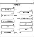
- the terminal device 3 is a portable electronic device such as a smartphone or a tablet terminal. As shown in FIG. 4, the terminal device 3 includes a display 30, an operation receiving unit 31, a first communication interface 32, a second communication interface 33, a GPS signal receiving circuit 34, a CPU 35, a ROM 36, and a RAM 37. And an auxiliary storage device 38. These components are connected to each other via a bus 39.
- the display 30 includes a display device such as a liquid crystal display and an organic EL (ElectroLuminescence) display.
- the display 30 displays various screens and the like according to user operations under the control of the CPU 35.
- the operation receiving unit 31 is configured to include one or more input devices such as a push button, a touch panel, and a touch pad, receives an operation input from a user, and sends a signal related to the received operation to the CPU 35.
- input devices such as a push button, a touch panel, and a touch pad
- the first communication interface 32 is hardware for communicating by a predetermined short-range wireless system. For example, when the terminal device 3 is possessed by a user at home H, the first communication interface 32 connects to the router 5 and communicates with the cloud server 4 via the Internet. When the terminal device 3 is possessed by a user who is out of the office, the first communication interface 32 connects to an AP (access point) (not shown) and communicates with the cloud server 4 via the Internet.
- AP access point
- the second communication interface 33 is hardware for communicating by a predetermined wide area wireless system.
- the second communication interface 33 connects to a base station (not shown) and communicates with the cloud server 4 via the Internet when the terminal device 3 is possessed by a user who is out and cannot connect to the AP. do.
- the GPS signal receiving circuit 34 is a circuit that receives GPS signals from GPS (Global Positioning System) satellites, calculates latitude and longitude based on the received GPS signals, and outputs them to the CPU 35.
- GPS Global Positioning System
- the CPU 35 comprehensively controls the terminal device 3.
- the ROM 36 stores a plurality of firmwares and data used when executing these firmwares.
- the RAM 37 is used as a work area of the CPU 35.
- the auxiliary storage device 38 is configured to include a readable / writable non-volatile semiconductor memory such as an EEPROM and a flash memory.
- the auxiliary storage device 38 stores various programs including application programs (hereinafter referred to as air conditioner applications) related to remote control and automatic operation of the air conditioner 2 and data used when executing these programs.
- the air conditioner application can be downloaded to the terminal device 3 from the cloud server 4, other program distribution server, or the like.
- the air conditioner application includes CD-ROM (Compact Disc Read Only Memory), DVD (Digital Versatile Disc), magneto-optical disc (Magneto-Optical Disc), USB (Universal Serial Bus) memory, memory card, HDD (Hard Disk). It is also possible to store and distribute it in a computer-readable recording medium such as Drive) or SSD (Solid State Drive).
- CD-ROM Compact Disc Read Only Memory
- DVD Digital Versatile Disc
- magneto-optical disc Magnetic-Optical Disc
- USB Universal Serial Bus
- memory card memory card
- HDD Hard Disk
- HDD Hard Disk
- the terminal device 3 accesses the cloud server 4 and displays an operation screen (not shown). Then, the terminal device 3 receives from the user, for example, an operation for instructing the start or stop of the cooling operation, the heating operation, the ventilation operation, the dehumidification operation, and the operation for instructing the change of the set temperature, the wind speed, the wind direction, and the like.
- the terminal device 3 transmits data indicating the content of the received operation to the cloud server 4, and the cloud server 4 controls the air conditioner 2 based on the content of the operation.
- the terminal device 3 when the air conditioner application is operating, the terminal device 3 periodically stores data (hereinafter, position) in which the ID (identification) of the terminal device 3 and the latitude and longitude calculated based on the GPS signal are stored. Data) is generated, and the generated location data is transmitted to the cloud server 4.
- the cloud server 4 is an example of a server.
- the cloud server 4 is a server computer installed and operated by a manufacturer, a sales company, or the like of the air conditioner 2, and is connected to the Internet.
- the cloud server 4 includes a communication interface 40, a CPU 41, a ROM 42, a RAM 43, and an auxiliary storage device 44. These components are connected to each other via the bus 45.
- the communication interface 40 is hardware for communicating with other devices via the Internet.
- the CPU 41 comprehensively controls the cloud server 4. Details of the functions of the cloud server 4 realized by the CPU 41 will be described later.
- the ROM 42 stores a plurality of firmwares and data used when executing these firmwares.
- the RAM 43 is used as a work area of the CPU 41.
- the auxiliary storage device 44 is a storage device including a readable / writable non-volatile semiconductor memory such as an EEPROM or a flash memory or an HDD.
- the auxiliary storage device 44 stores a program for supporting the automatic operation of the air conditioner 2 (hereinafter referred to as an automatic operation support program) and data used when the automatic operation support program is executed.
- the auxiliary storage device 44 stores various programs including a program for realizing remote control of the air conditioner 2 by the user, and data used when executing these programs.
- the above-mentioned automatic operation support program can be downloaded to the cloud server 4 from another server installed and operated by the manufacturer, sales company, etc. of the air conditioner 2. Further, the automatic operation support program can be stored and distributed in a computer-readable recording medium such as a CD-ROM, a DVD, a magneto-optical disk, a USB memory, a memory card, an HDD, or an SSD.
- a computer-readable recording medium such as a CD-ROM, a DVD, a magneto-optical disk, a USB memory, a memory card, an HDD, or an SSD.
- the air conditioning system 1 has a function of starting automatic operation at an appropriate timing so that the room temperature of the room R becomes the target temperature when the user who is out of the office returns home (hereinafter,). , It has an automatic operation start function).
- the target temperature is a temperature that the user feels comfortable immediately after returning home, and is generally a temperature several ° C lower during the heating operation and several ° C higher during the cooling operation than the set temperature of the room R.
- FIG. 6 is a block diagram showing the functional configurations of the air conditioner 2 and the cloud server 4 for realizing the above-mentioned automatic operation start function.
- the air conditioner 2 includes an arrival required time request unit 220, an arrival required time acquisition unit 221, a learning unit 222, a time constant calculation unit 223, an air conditioning required time calculation unit 224, and operation control.
- a unit 225 is provided.
- These functional units of the air conditioner 2 are realized by the CPU in the control circuit 200 of the indoor unit 20 executing an air conditioning program stored in the auxiliary storage device of the control circuit 200.
- the function of the air conditioner 2 shown in FIG. 6 is a characteristic function of the air conditioner 2 in the present embodiment.
- the air conditioner 2 includes a function provided by a general air conditioner, a terminal device 3. It has a function to perform air conditioning based on the remote operation of the user via the user, but the description of these functions will be omitted.
- the cloud server 4 includes a position data acquisition unit 400, an arrival required time calculation unit 401, and an arrival required time transmission unit 402. These functional units of the cloud server 4 are realized by the CPU 41 executing the above-mentioned automatic driving support program stored in the auxiliary storage device 44.
- the function of the cloud server 4 shown in FIG. 6 is a characteristic function of the cloud server 4 in the present embodiment.
- the cloud server 4 has a function of accepting user registration from a user, a terminal device 3. It is provided with a function of controlling the air conditioner 2 based on a remote control of the user via the user, but description of these functions will be omitted.
- the position data acquisition unit 400 receives and acquires the above-mentioned position data periodically sent from the terminal device 3.
- the position data acquisition unit 400 stores the acquired position data in the customer DB 440.
- the customer DB 440 is a database for managing information about the user of the air conditioner 2 and the user (that is, the customer) who has registered the user, and is stored in the auxiliary storage device 44.
- Customer information and location data history are stored in the customer DB 440 for each customer.
- the customer information is information registered in the customer DB 440 by prior user registration via the terminal device 3 by the user, and is, for example, a user ID, a password, identification information of the air conditioner 2, and location information of the house H (for example, latitude). And longitude, address, etc.), ID of the terminal device 3, etc. are included.
- the identification information of the air conditioner 2 includes, for example, the serial number of the air conditioner 2.
- the arrival required time requesting unit 220 periodically transmits to the cloud server 4 the arrival required time, which is the time required for the user who is out to arrive at the house H (that is, return home). Request. Specifically, the arrival required time request unit 220 transmits data indicating such a request (hereinafter referred to as request data) to the cloud server 4 via the Internet.
- request data data indicating such a request
- the arrival time calculation unit 401 of the cloud server 4 is an example of the arrival time calculation means. Upon receiving the above-mentioned request data sent from the air conditioner 2, the arrival required time calculation unit 401 calculates the arrival required time of the user. Specifically, the arrival time calculation unit 401 has a history of position data sent from the terminal device 3 owned by the user of the air conditioner 2 stored in the customer DB 440, and the position of the user's house H. Based on the information, the arrival time of the user is calculated.
- the arrival time calculation unit 401 determines the current position of the user (more specifically, the terminal device 3) and the position of the house H based on the latest position data and the position information of the house H. The distance between (hereinafter referred to as the user distance) is calculated. Further, the arrival required time calculation unit 401 calculates the movement speed of the user in the direction of the house H from the history of the position data. The arrival required time calculation unit 401 calculates the arrival required time from the calculated user distance and moving speed. The arrival required time calculation unit 401 supplies the calculated arrival required time to the arrival required time transmission unit 402.
- the arrival required time calculation unit 401 calculates the arrival required time without calculating the arrival required time.
- a predetermined time for example, 0 minutes
- a predetermined time indicating that it is impossible is supplied to the arrival required time transmission unit 402 as an arrival required time.
- the arrival time transmission unit 402 is an example of the arrival time transmission means.
- the arrival required time transmitting unit 402 transmits the data (hereinafter referred to as response data) in which the arrival required time is stored to the request data via the Internet. Send to the original air conditioner 2.
- the arrival required time acquisition unit 221 is an example of the arrival required time acquisition means.
- the arrival required time acquisition unit 221 receives the response data sent from the cloud server 4, extracts the arrival required time from the received response data, and acquires it.
- the arrival required time acquisition unit 221 supplies the acquired arrival required time to the operation control unit 225.
- the learning unit 222 is an example of learning means.
- the learning unit 222 derives the first approximate expression f1 and the second approximate expression f2 for calculating the time constant ⁇ by learning.
- the significance of the time constant ⁇ in the present embodiment will be described in detail with reference to FIGS. 7 to 10.
- 7 to 10 show an example of the transition of the room temperature or the air conditioning capacity (that is, the heating capacity) after the air conditioner 2 starts the heating operation.
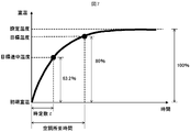
- 7 shows the transition of the room temperature
- FIG. 8 shows the transition of the air conditioning capacity
- FIG. 9 shows the transition of the room temperature according to the size of the heat capacity of the room
- FIG. 10 shows the transition of the air conditioning capacity of the heat capacity of the room. Shown by size.
- the air conditioner 2 like a general air conditioner, weakens the air conditioning capacity as the room temperature approaches the set temperature to moderate the change in the room temperature. Specifically, the air conditioner 2 controls the air conditioning capacity according to the difference between the set temperature and the room temperature. For example, in the range of the temperature rise rate of 0 to 70% during the heating operation, the room is operated with the maximum air conditioning capacity (that is, the maximum heating capacity) in order to warm the room temperature quickly (hereinafter, this area is referred to as a starting area).
- the maximum air conditioning capacity that is, the maximum heating capacity
- this area is referred to as a transition area
- the room temperature almost coincides with the set temperature. Maintain heating capacity wherever possible (hereinafter, this area is referred to as the stable area).
- the room temperature change is small because the operation is performed with almost constant air conditioning capacity.
- the air-conditioning capacity changes depending on the conditions, and the room temperature changes slowly, so that variations are likely to occur.
- T-Tini (Tset-Tini) ⁇ (1-e- t / ⁇ ) (Equation 1)
- the time constant ⁇ is an example of the first required time. From Equation 1, the time constant ⁇ is the time required to reach a temperature 63.2% higher than the initial room temperature (that is, the room temperature at the start of heating) of the temperature difference between the set temperature and the initial room temperature during the heating operation. Is. The room temperature when the time constant ⁇ is below is called the target intermediate temperature.
- the time required to reach the predetermined target temperature can be easily calculated from the above equation 1.
- this required time is referred to as air conditioning required time.
- the air conditioning required time is an example of the second required time.
- the time required for air conditioning is the time constant ⁇ ⁇ 1.6.
- the time constant ⁇ differs depending on the heat capacity of the room (the amount of heat required to raise the room temperature by 1 ° C).
- the heat capacity of a room is determined by the size of the room, the difference in structure such as reinforced concrete and wooden construction, the type of building materials (physical characteristics of the materials used for walls, floors and ceilings), and the amount of furniture.
- 9 and 10 show a comparison between a room having a small heat capacity and a room having a large heat capacity.
- the learning unit 222 derives the first approximate expression f1 (Tset, Tini) and the second approximate expression f2 (To: outside air temperature) for calculating an appropriate time constant ⁇ by learning.
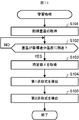
- FIG. 11 is a flowchart showing the procedure of the learning process executed by the learning unit 222. The learning process is executed every time the air conditioning operation is started, regardless of whether it is an automatic operation or a manual operation.
- the learning unit 222 acquires the room temperature of the room R at the start of operation, that is, the initial room temperature (step S101).
- the learning unit 222 determines whether or not the room temperature has reached the target midway temperature (step S102).
- the learning unit 222 acquires the elapsed time from the start of operation, that is, the time constant ⁇ (step S103).
- the learning unit 222 derives the first approximate expression f1 (Tset, Tini) (step S104).
- FIG. 12 shows a plot example of the time constant ⁇ obtained by repeating the learning process during the heating operation a plurality of times.
- the temperature difference ⁇ T between the set temperature and the initial room temperature is on the horizontal axis
- the time constant ⁇ is on the vertical axis.
- the larger the temperature difference ⁇ T the larger the amount of heat for changing the temperature from the initial room temperature to the set temperature with respect to the heat capacity of the room R. Therefore, when the air conditioner 2 operates with a constant air conditioning capacity.
- the time constant ⁇ increases.
- the learning unit 222 derives the first approximate expression f1 (Tset, Tini) by calculating the slope of the linear approximate expression of the time constant ⁇ with respect to the temperature difference ⁇ T from the plot of the time constant ⁇ .
- the learning unit 222 derives the second approximate expression f2 (To) (step S105).
- ⁇ be the deviation between the first approximate expression f1 (Tset, Tini) and the time constant ⁇ (see FIG. 13).
- FIG. 14 shows a plot example of the deviation ⁇ obtained by repeating the learning process during the heating operation a plurality of times.
- the outside air temperature is on the horizontal axis and the deviation ⁇ is on the vertical axis.
- the time constant ⁇ increases more than the first approximate expression f1 (Tset, Tini) ( ⁇ is positive).
- the learning unit 222 derives the second approximate expression f2 (To) by calculating the slope and intercept of the linear approximate expression of the deviation ⁇ with respect to the outside temperature from the plot of the deviation ⁇ .
- the time constant calculation unit 223 is an example of the first required time acquisition means.
- the time constant calculation unit 223 starts the air conditioning of the room R based on the parameters of the set temperature, the initial room temperature and the outside air temperature, and the learning result of the learning unit 222, and then the room temperature of the room R reaches the target intermediate temperature.
- Calculate the time constant ⁇ which is the time required to complete the process.
- the time constant calculation unit 223 calculates the time constant ⁇ by the following equation 2.
- the air conditioning required time calculation unit 224 is an example of the second required time acquisition means.
- the air-conditioning required time calculation unit 224 calculates the air-conditioning required time, which is the time required from the start of air-conditioning of the room R to the time when the room temperature of the room R reaches the target temperature. Specifically, the air conditioning required time calculation unit 224 calculates the air conditioning required time based on the time constant ⁇ calculated by the time constant calculation unit 223, the target temperature, and the above equation 1.
- the air-conditioning required time calculation unit 224 supplies the calculated air-conditioning required time to the operation control unit 225.
- the operation control unit 225 is an example of the operation control means.
- the operation control unit 225 compares the arrival required time with the air conditioning required time calculated by the air conditioning required time calculation unit 224. When the arrival time is within the air conditioning time, the air conditioning operation is started.
- FIG. 15 is a flowchart showing a procedure of automatic operation start processing executed by the air conditioner 2.
- the air conditioner 2 repeatedly executes the automatic operation start process periodically (for example, at a 1-minute cycle) when the operation is stopped.
- the air conditioner 2 acquires the arrival time, which is the time required for the user who is out of the office to arrive at the house H (that is, return home) from the cloud server 4 (step S201).
- the air conditioner 2 calculates the required air conditioning time, which is the time required from the start of air conditioning of the room R until the room temperature of the room R reaches the target temperature (step S202). Then, the air conditioner 2 determines whether or not the acquired arrival required time is within the calculated air conditioning required time (step S203).
- step S203 If it is determined that the arrival time is not within the air conditioning time (step S203; NO), the air conditioner 2 ends the automatic operation start process in this cycle.
- step S203 when it is determined that the arrival time is within the air conditioning time (step S203; YES), the air conditioner 2 starts the air conditioning operation (step S204) and ends the automatic operation start process in this cycle.
- the air conditioner 2 has a time constant ⁇ which is the time required for the initial room temperature of the room R to reach the target intermediate temperature which is the room temperature in the starting range. Calculate and calculate the air conditioning required time based on the calculated time constant ⁇ . Therefore, it is possible to accurately obtain the time required for the room temperature to reach the target temperature after the air conditioning of the room R is started. As a result, when the user goes out, automatic operation can be started at an appropriate timing, and comfort and energy saving can be improved.
- time constant ⁇ is calculated based on the first approximate expression f1 (Tset, Tini) and the second approximate expression f2 (To) derived by learning, it is appropriate according to the heat capacity of the room R.
- the time constant ⁇ can be obtained.
- the automatic operation start function has been described by taking the heating operation as an example, but the technical idea of the present disclosure is of course applicable to the cooling operation.
- the target intermediate temperature which is the room temperature in the starting range during the heating operation, is increased by 63.2% from the initial room temperature to the temperature difference between the set temperature and the initial room temperature based on the above equation 1.
- the target intermediate temperature may be determined by a suitable exponential expression based on the specifications of the target air conditioner.
- the target intermediate temperature is a constant c (> 0) obtained from the set temperature and the specifications of the air conditioner, such as set temperature-constant c in the case of heating operation and set temperature + constant c in the case of cooling operation. It may be determined based on °C).
- meteorological information such as the amount of solar radiation and the weather
- indoor information such as the temperature of the floor, wall or window, the open / closed state of the door, and the presence / absence of internal heat generation may be adopted.
- the weather information may be acquired from the weather server (not shown) via the cloud server 4, or may be acquired directly from the weather server.
- the indoor information can be acquired by the air conditioner 2 by analyzing the thermal image data acquired by the thermal image sensor 205.
- first approximate expression f1 may be derived and used according to the season, month, time zone, time, and the like.
- the target temperature may be registered in the air conditioner 2 in advance via the terminal device 3 or the air conditioner remote control 6, or the user may perform air conditioning based on the physical information of the user registered in the air conditioner 2 in advance. It may be set automatically by the machine 2. Physical information includes, for example, characteristics for a thermal environment (hot, cold, etc.), gender, age, weight, height, and the like.
- the air conditioner 2 may set the target temperature based on information such as the amount of clothes worn by the user, the feeling of warmth and coldness, and the amount of activity. The air conditioner 2 can acquire the amount of clothes and the feeling of warmth and coldness of the user by analyzing the thermal image data when the user is at home.
- the air conditioner 2 can acquire the activity amount of the user from the cloud server 4.
- the cloud server 4 calculates the amount of user activity based on the user's moving speed, pre-registered moving means (walking, bus, train, car, etc.), step count data acquired from the terminal device 3, and the like.
- the cloud server 4 may calculate the amount of user activity based on the user's biometric data acquired by communication with the wearable sensor. good.
- Biological data includes body temperature, heart rate, sweating amount and the like.
- the cloud server 4 may manage the physical information of the user and the like by the customer DB 440. Further, the cloud server 4 may be configured to determine the target temperature as described above and notify the determined target temperature to the air conditioner 2.
- the air conditioner 2 has a time measuring unit (an example of a time measuring means) for measuring the time from the start of automatic operation until the user arrives at the house H, and the user arrives at the house H. Further equipped with an arrival room temperature acquisition unit (an example of an arrival room temperature acquisition means) for acquiring the room temperature of the room R at the time, the air conditioner required time calculation unit 224 is a time clocked by the timekeeping unit and an arrival room temperature acquisition unit. The correction value ⁇ to be used in the next calculation of the required air conditioning time may be determined based on the room temperature obtained by.
- the air conditioning required time calculation unit 224 adds the correction value ⁇ (> 0 minutes) to the time calculated based on the time constant ⁇ , the target temperature, and the above equation 1 to obtain the air conditioning required time. Is calculated. This makes it possible to absorb variations in the time required for air conditioning, and to link various map applications (that is, various algorithms for estimating the time required for arrival) made by other companies with the air conditioner 2.
- the arrival required time calculation unit 401 of the cloud server 4 may calculate the above user distance and / or the arrival required time each time the position data is acquired from the terminal device 3.
- the air conditioner 2 does not unconditionally and periodically periodically periodically execute the automatic operation start process (see FIG. 15) when the operation is stopped, but the automatic operation start process is triggered by the reception of the process start command from the cloud server 4. May start periodic execution of.
- the cloud server 4 may send a processing start command to the air conditioner 2 when the user distance is within a predetermined distance (for example, the above upper limit distance), or the arrival time may be a predetermined upper limit time.
- the processing start command may be transmitted to the air conditioner 2, or the processing start command may be transmitted to the air conditioner 2 when a predetermined operation is performed by the user via the terminal device 3.
- the cloud server 4 may transmit a processing stop command to the air conditioner 2 when the user distance exceeds the upper limit distance, or transmit a processing stop command to the air conditioner 2 when the arrival required time exceeds the upper limit time.
- the processing stop command may be transmitted to the air conditioner 2 when a predetermined operation is performed by the user via the terminal device 3.
- the air conditioner 2 Upon receiving the processing stop command from the cloud server 4, the air conditioner 2 cancels the periodic execution of the automatic operation start processing.
- the terminal device 3 may calculate the arrival required time and notify the calculated arrival required time to the air conditioner 2 via the cloud server 4 or directly, or the air conditioner 2 may use the terminal.
- the arrival time may be calculated based on the position data directly or indirectly received from the device 3.
- the function of the air conditioner 2 may be realized by the control circuit 210 of the outdoor unit 21.
- the cloud server 4, the terminal device 3, or the air conditioning remote controller 6 is, as an example of the control device, all or one of the learning unit 222, the time constant calculation unit 223, the air conditioning required time calculation unit 224, and the operation control unit 225 in the air conditioner 2. It may be provided with the function of the unit.
- a device such as a HEMS (Home Energy Management System) controller installed in the house H may be provided with the same function as the cloud server 4 (see FIG. 6), or may be a control device.
- the air conditioner 2 may be provided with all or part of the functions of the learning unit 222, the time constant calculation unit 223, the air conditioning required time calculation unit 224, and the operation control unit 225.
- the communication between the indoor unit 20 of the air conditioner 2 and the cloud server 4 may be performed based on LPWA (Low Power Wide Area) in 5G (5th generation mobile communication system).
- LPWA Low Power Wide Area
- the air conditioner 2 may be configured to communicate with the cloud server 4 via an external communication adapter (not shown) without incorporating the communication interface 206.
- the air conditioner 2 may be installed in each of the plurality of rooms in the house H.
- each air conditioner 2 holds in advance the ID of the terminal device 3 possessed by the user corresponding to the room in which the air conditioner 2 is installed. Then, each air conditioner 2 acquires the arrival time required for the user who possesses the terminal device 3 from the cloud server 4 by designating the ID of the terminal device 3, and executes the automatic operation start process (see FIG. 15). ..
- all or part of the functional part of the air conditioner 2 may be realized by dedicated hardware, or all or one of the functional parts of the cloud server 4 (see FIG. 6).
- the part may be realized by dedicated hardware.
- the dedicated hardware is, for example, a single circuit, a composite circuit, a programmed processor, an ASIC (Application Specific Integrated Circuit), an FPGA (Field-Programmable Gate Array), or a combination thereof.
- This disclosure is also applicable to systems that air-condition buildings other than houses.
- This disclosure can be suitably adopted for an air conditioning system that air-conditions a building.
Landscapes
- Engineering & Computer Science (AREA)
- Chemical & Material Sciences (AREA)
- Combustion & Propulsion (AREA)
- Mechanical Engineering (AREA)
- General Engineering & Computer Science (AREA)
- Human Computer Interaction (AREA)
- Signal Processing (AREA)
- Physics & Mathematics (AREA)
- Fuzzy Systems (AREA)
- Mathematical Physics (AREA)
- Air Conditioning Control Device (AREA)
Priority Applications (5)
| Application Number | Priority Date | Filing Date | Title |
|---|---|---|---|
| JP2022533293A JP7313563B2 (ja) | 2020-06-29 | 2020-06-29 | 空調機、制御装置、空調システム及び空調方法 |
| EP20942465.4A EP4174393A4 (en) | 2020-06-29 | 2020-06-29 | AIR CONDITIONING CONTROL DEVICE, CLIMATE CONTROL SYSTEM AND CLIMATE CONTROL METHOD |
| US17/922,424 US20230194114A1 (en) | 2020-06-29 | 2020-06-29 | Air conditioner, control device, air conditioning system, and air conditioning method |
| CN202080102279.8A CN115867753A (zh) | 2020-06-29 | 2020-06-29 | 空调机、控制装置、空调系统以及空调方法 |
| PCT/JP2020/025588 WO2022003797A1 (ja) | 2020-06-29 | 2020-06-29 | 空調機、制御装置、空調システム及び空調方法 |
Applications Claiming Priority (1)
| Application Number | Priority Date | Filing Date | Title |
|---|---|---|---|
| PCT/JP2020/025588 WO2022003797A1 (ja) | 2020-06-29 | 2020-06-29 | 空調機、制御装置、空調システム及び空調方法 |
Publications (1)
| Publication Number | Publication Date |
|---|---|
| WO2022003797A1 true WO2022003797A1 (ja) | 2022-01-06 |
Family
ID=79315806
Family Applications (1)
| Application Number | Title | Priority Date | Filing Date |
|---|---|---|---|
| PCT/JP2020/025588 Ceased WO2022003797A1 (ja) | 2020-06-29 | 2020-06-29 | 空調機、制御装置、空調システム及び空調方法 |
Country Status (5)
| Country | Link |
|---|---|
| US (1) | US20230194114A1 (https=) |
| EP (1) | EP4174393A4 (https=) |
| JP (1) | JP7313563B2 (https=) |
| CN (1) | CN115867753A (https=) |
| WO (1) | WO2022003797A1 (https=) |
Cited By (1)
| Publication number | Priority date | Publication date | Assignee | Title |
|---|---|---|---|---|
| JP2024022102A (ja) * | 2022-08-05 | 2024-02-16 | 三菱電機ビルソリューションズ株式会社 | 空調制御システムおよび制御方法 |
Families Citing this family (1)
| Publication number | Priority date | Publication date | Assignee | Title |
|---|---|---|---|---|
| CN119468418B (zh) * | 2024-11-26 | 2025-05-27 | 浙江尼普顿科技股份有限公司 | 基于大数据驱动的空调设备群节能控制方法及系统 |
Citations (4)
| Publication number | Priority date | Publication date | Assignee | Title |
|---|---|---|---|---|
| JPS6293702A (ja) * | 1985-10-18 | 1987-04-30 | Matsushita Seiko Co Ltd | 最適始動制御装置 |
| JP2005344970A (ja) * | 2004-06-01 | 2005-12-15 | Hokuto Denshi Kogyo Kk | 消費電力削減量の評価支援方法、評価支援装置、および電力制御装置 |
| JP2006284477A (ja) | 2005-04-04 | 2006-10-19 | Denso Corp | 車両用ナビゲーション装置及び住宅内機器遠隔操作システム |
| JP2014071002A (ja) * | 2012-09-28 | 2014-04-21 | Denso Corp | 宅内空調装置遠隔操作システム |
Family Cites Families (11)
| Publication number | Priority date | Publication date | Assignee | Title |
|---|---|---|---|---|
| JPH05118608A (ja) * | 1991-10-25 | 1993-05-14 | Hitachi Home Tec Ltd | 暖房器のタイマ運転制御装置 |
| JP2007051799A (ja) * | 2005-08-16 | 2007-03-01 | Toshiba Kyaria Kk | 空気調和機の遠隔操作システム |
| CN104487778B (zh) * | 2012-07-23 | 2017-05-17 | 三菱电机株式会社 | 空调装置以及空调控制方法 |
| JP2014040969A (ja) * | 2012-08-23 | 2014-03-06 | Daikin Ind Ltd | 空気調和機 |
| JP2015095721A (ja) * | 2013-11-11 | 2015-05-18 | 株式会社デンソー | 家電遠隔制御システム、車載装置 |
| US20150370272A1 (en) * | 2014-06-23 | 2015-12-24 | Google Inc. | Intelligent configuration of a smart environment based on arrival time |
| CN104197468B (zh) * | 2014-08-20 | 2017-04-05 | 美的集团股份有限公司 | 空调运行参数处理方法及装置 |
| WO2017056403A1 (ja) * | 2015-10-01 | 2017-04-06 | パナソニックIpマネジメント株式会社 | 空調制御方法、空調制御装置及び空調制御プログラム |
| JP2017216572A (ja) * | 2016-05-31 | 2017-12-07 | シャープ株式会社 | サーバおよびその制御方法、並びに制御プログラム |
| JP6876399B2 (ja) * | 2016-09-28 | 2021-05-26 | トヨタホーム株式会社 | 屋内環境調整システム |
| CN107975918B (zh) * | 2017-11-21 | 2020-10-13 | 广东美的暖通设备有限公司 | 空调系统、空调系统的控制方法和装置 |
-
2020
- 2020-06-29 JP JP2022533293A patent/JP7313563B2/ja active Active
- 2020-06-29 WO PCT/JP2020/025588 patent/WO2022003797A1/ja not_active Ceased
- 2020-06-29 EP EP20942465.4A patent/EP4174393A4/en not_active Withdrawn
- 2020-06-29 US US17/922,424 patent/US20230194114A1/en not_active Abandoned
- 2020-06-29 CN CN202080102279.8A patent/CN115867753A/zh active Pending
Patent Citations (4)
| Publication number | Priority date | Publication date | Assignee | Title |
|---|---|---|---|---|
| JPS6293702A (ja) * | 1985-10-18 | 1987-04-30 | Matsushita Seiko Co Ltd | 最適始動制御装置 |
| JP2005344970A (ja) * | 2004-06-01 | 2005-12-15 | Hokuto Denshi Kogyo Kk | 消費電力削減量の評価支援方法、評価支援装置、および電力制御装置 |
| JP2006284477A (ja) | 2005-04-04 | 2006-10-19 | Denso Corp | 車両用ナビゲーション装置及び住宅内機器遠隔操作システム |
| JP2014071002A (ja) * | 2012-09-28 | 2014-04-21 | Denso Corp | 宅内空調装置遠隔操作システム |
Non-Patent Citations (1)
| Title |
|---|
| See also references of EP4174393A4 |
Cited By (2)
| Publication number | Priority date | Publication date | Assignee | Title |
|---|---|---|---|---|
| JP2024022102A (ja) * | 2022-08-05 | 2024-02-16 | 三菱電機ビルソリューションズ株式会社 | 空調制御システムおよび制御方法 |
| JP7734635B2 (ja) | 2022-08-05 | 2025-09-05 | 三菱電機ビルソリューションズ株式会社 | 空調制御システムおよび制御方法 |
Also Published As
| Publication number | Publication date |
|---|---|
| JP7313563B2 (ja) | 2023-07-24 |
| JPWO2022003797A1 (https=) | 2022-01-06 |
| EP4174393A4 (en) | 2023-08-02 |
| EP4174393A1 (en) | 2023-05-03 |
| CN115867753A (zh) | 2023-03-28 |
| US20230194114A1 (en) | 2023-06-22 |
Similar Documents
| Publication | Publication Date | Title |
|---|---|---|
| CN103994545B (zh) | 空调器的控制方法、智能终端和空调器控制系统 | |
| JP6025833B2 (ja) | 空調装置および空気調和システム | |
| EP2333442B1 (en) | Air conditioner controller | |
| JP6125040B2 (ja) | 空調制御装置 | |
| US20250354715A1 (en) | Wireless remote indoor sensor for home automation | |
| JP6125039B2 (ja) | 空調制御装置 | |
| JP2021050862A (ja) | 空気調和機 | |
| JP2013200098A (ja) | 空気調和装置 | |
| JP7050760B2 (ja) | 空調装置、制御装置、空調方法及びプログラム | |
| JP6494562B2 (ja) | 制御装置、空調システム、制御方法、及び、プログラム | |
| JP2010261617A (ja) | 空気調和システム | |
| JP7086219B2 (ja) | 空調機、制御装置、空調システム、空調制御方法及びプログラム | |
| JP7313563B2 (ja) | 空調機、制御装置、空調システム及び空調方法 | |
| JPWO2020148864A1 (ja) | 空気調和制御システム | |
| JP2019020034A (ja) | 空気調和機 | |
| JP2020125868A (ja) | 空気調和システム | |
| JP2019184154A (ja) | 空調装置 | |
| JP7433458B2 (ja) | 制御装置、換気システム、空調装置、換気制御方法及びプログラム | |
| JP7089869B2 (ja) | 空調システム及び制御装置 | |
| JP2019039575A (ja) | 空気調和システム | |
| KR102203206B1 (ko) | 중앙 제어기 및 이를 포함하는 공기조화 시스템 | |
| JP2021071243A (ja) | 空気調和システム及び空気調和機 | |
| JP2023147391A (ja) | 空調システム | |
| JP2016061525A (ja) | 通風制御装置、通風制御システム、プログラム | |
| WO2023181324A1 (ja) | 空調制御装置、空調システム、空調制御方法及びプログラム |
Legal Events
| Date | Code | Title | Description |
|---|---|---|---|
| 121 | Ep: the epo has been informed by wipo that ep was designated in this application |
Ref document number: 20942465 Country of ref document: EP Kind code of ref document: A1 |
|
| ENP | Entry into the national phase |
Ref document number: 2022533293 Country of ref document: JP Kind code of ref document: A |
|
| NENP | Non-entry into the national phase |
Ref country code: DE |
|
| ENP | Entry into the national phase |
Ref document number: 2020942465 Country of ref document: EP Effective date: 20230130 |