WO2021251232A1 - 密封装置 - Google Patents
密封装置 Download PDFInfo
- Publication number
- WO2021251232A1 WO2021251232A1 PCT/JP2021/020973 JP2021020973W WO2021251232A1 WO 2021251232 A1 WO2021251232 A1 WO 2021251232A1 JP 2021020973 W JP2021020973 W JP 2021020973W WO 2021251232 A1 WO2021251232 A1 WO 2021251232A1
- Authority
- WO
- WIPO (PCT)
- Prior art keywords
- sleeve
- protrusion
- cylindrical portion
- sealing
- sealing device
- Prior art date
- Legal status (The legal status is an assumption and is not a legal conclusion. Google has not performed a legal analysis and makes no representation as to the accuracy of the status listed.)
- Ceased
Links
Images



Classifications
-
- F—MECHANICAL ENGINEERING; LIGHTING; HEATING; WEAPONS; BLASTING
- F16—ENGINEERING ELEMENTS AND UNITS; GENERAL MEASURES FOR PRODUCING AND MAINTAINING EFFECTIVE FUNCTIONING OF MACHINES OR INSTALLATIONS; THERMAL INSULATION IN GENERAL
- F16J—PISTONS; CYLINDERS; SEALINGS
- F16J15/00—Sealings
- F16J15/16—Sealings between relatively-moving surfaces
- F16J15/32—Sealings between relatively-moving surfaces with elastic sealings, e.g. O-rings
- F16J15/3248—Sealings between relatively-moving surfaces with elastic sealings, e.g. O-rings provided with casings or supports
- F16J15/3252—Sealings between relatively-moving surfaces with elastic sealings, e.g. O-rings provided with casings or supports with rigid casings or supports
- F16J15/3256—Sealings between relatively-moving surfaces with elastic sealings, e.g. O-rings provided with casings or supports with rigid casings or supports comprising two casing or support elements, one attached to each surface, e.g. cartridge or cassette seals
- F16J15/3264—Sealings between relatively-moving surfaces with elastic sealings, e.g. O-rings provided with casings or supports with rigid casings or supports comprising two casing or support elements, one attached to each surface, e.g. cartridge or cassette seals the elements being separable from each other
-
- F—MECHANICAL ENGINEERING; LIGHTING; HEATING; WEAPONS; BLASTING
- F16—ENGINEERING ELEMENTS AND UNITS; GENERAL MEASURES FOR PRODUCING AND MAINTAINING EFFECTIVE FUNCTIONING OF MACHINES OR INSTALLATIONS; THERMAL INSULATION IN GENERAL
- F16C—SHAFTS; FLEXIBLE SHAFTS; ELEMENTS OR CRANKSHAFT MECHANISMS; ROTARY BODIES OTHER THAN GEARING ELEMENTS; BEARINGS
- F16C33/00—Parts of bearings; Special methods for making bearings or parts thereof
- F16C33/72—Sealings
- F16C33/76—Sealings of ball or roller bearings
- F16C33/78—Sealings of ball or roller bearings with a diaphragm, disc, or ring, with or without resilient members
- F16C33/7816—Details of the sealing or parts thereof, e.g. geometry, material
- F16C33/782—Details of the sealing or parts thereof, e.g. geometry, material of the sealing region
-
- F—MECHANICAL ENGINEERING; LIGHTING; HEATING; WEAPONS; BLASTING
- F16—ENGINEERING ELEMENTS AND UNITS; GENERAL MEASURES FOR PRODUCING AND MAINTAINING EFFECTIVE FUNCTIONING OF MACHINES OR INSTALLATIONS; THERMAL INSULATION IN GENERAL
- F16C—SHAFTS; FLEXIBLE SHAFTS; ELEMENTS OR CRANKSHAFT MECHANISMS; ROTARY BODIES OTHER THAN GEARING ELEMENTS; BEARINGS
- F16C33/00—Parts of bearings; Special methods for making bearings or parts thereof
- F16C33/72—Sealings
- F16C33/76—Sealings of ball or roller bearings
- F16C33/78—Sealings of ball or roller bearings with a diaphragm, disc, or ring, with or without resilient members
- F16C33/7816—Details of the sealing or parts thereof, e.g. geometry, material
- F16C33/782—Details of the sealing or parts thereof, e.g. geometry, material of the sealing region
- F16C33/7823—Details of the sealing or parts thereof, e.g. geometry, material of the sealing region of sealing lips
-
- F—MECHANICAL ENGINEERING; LIGHTING; HEATING; WEAPONS; BLASTING
- F16—ENGINEERING ELEMENTS AND UNITS; GENERAL MEASURES FOR PRODUCING AND MAINTAINING EFFECTIVE FUNCTIONING OF MACHINES OR INSTALLATIONS; THERMAL INSULATION IN GENERAL
- F16C—SHAFTS; FLEXIBLE SHAFTS; ELEMENTS OR CRANKSHAFT MECHANISMS; ROTARY BODIES OTHER THAN GEARING ELEMENTS; BEARINGS
- F16C33/00—Parts of bearings; Special methods for making bearings or parts thereof
- F16C33/72—Sealings
- F16C33/76—Sealings of ball or roller bearings
- F16C33/78—Sealings of ball or roller bearings with a diaphragm, disc, or ring, with or without resilient members
- F16C33/7869—Sealings of ball or roller bearings with a diaphragm, disc, or ring, with or without resilient members mounted with a cylindrical portion to the inner surface of the outer race and having a radial portion extending inward
- F16C33/7879—Sealings of ball or roller bearings with a diaphragm, disc, or ring, with or without resilient members mounted with a cylindrical portion to the inner surface of the outer race and having a radial portion extending inward with a further sealing ring
- F16C33/7883—Sealings of ball or roller bearings with a diaphragm, disc, or ring, with or without resilient members mounted with a cylindrical portion to the inner surface of the outer race and having a radial portion extending inward with a further sealing ring mounted to the inner race and of generally L-shape, the two sealing rings defining a sealing with box-shaped cross-section
-
- F—MECHANICAL ENGINEERING; LIGHTING; HEATING; WEAPONS; BLASTING
- F16—ENGINEERING ELEMENTS AND UNITS; GENERAL MEASURES FOR PRODUCING AND MAINTAINING EFFECTIVE FUNCTIONING OF MACHINES OR INSTALLATIONS; THERMAL INSULATION IN GENERAL
- F16J—PISTONS; CYLINDERS; SEALINGS
- F16J15/00—Sealings
- F16J15/16—Sealings between relatively-moving surfaces
- F16J15/32—Sealings between relatively-moving surfaces with elastic sealings, e.g. O-rings
- F16J15/3268—Mounting of sealing rings
- F16J15/3276—Mounting of sealing rings with additional static sealing between the sealing, or its casing or support, and the surface on which it is mounted
-
- F—MECHANICAL ENGINEERING; LIGHTING; HEATING; WEAPONS; BLASTING
- F16—ENGINEERING ELEMENTS AND UNITS; GENERAL MEASURES FOR PRODUCING AND MAINTAINING EFFECTIVE FUNCTIONING OF MACHINES OR INSTALLATIONS; THERMAL INSULATION IN GENERAL
- F16C—SHAFTS; FLEXIBLE SHAFTS; ELEMENTS OR CRANKSHAFT MECHANISMS; ROTARY BODIES OTHER THAN GEARING ELEMENTS; BEARINGS
- F16C2326/00—Articles relating to transporting
- F16C2326/01—Parts of vehicles in general
- F16C2326/02—Wheel hubs or castors
Definitions
- the present invention relates to a sealing device.
- the hub of an automobile is provided with rolling bearings that support the axle.
- This rolling bearing is called a hub bearing.
- a sealing device is provided between the inner ring and the outer ring of the hub bearing. This sealing device seals the lubricant (grease) inside the bearing and prevents foreign substances such as water and dust from entering the inside of the bearing from the outside.
- One type of sealing device provided on a hub bearing is a combination of two sealing members (Patent Document 1).
- One sealing member is attached to an outer member, eg, an outer ring, and the other sealing member is attached to an inner member, eg, an inner ring.
- One sealing member is provided with a lip that slidably contacts the other sealing member, which prevents the lubricant from leaking.
- the seal member attached to the inner member has a sleeve into which the inner member is fitted and a flange extending radially outward from the sleeve.
- the flange of the sealing member described in Patent Document 1 has a metal flange portion and an elastic flange portion made of an elastic material.
- the sleeve of the above-mentioned sealing member and the inner member fitted into the sleeve are made of a rigid material, and a minute gap may occur between them.
- the present invention provides a sealing device capable of maintaining the sealing property of the internal space.
- the sealing device is arranged between a relatively rotating inner member and an outer member, and seals a gap between the inner member and the outer member.
- the sealing device is fitted with a cylindrical portion attached to the outer member, an annular portion extending radially inward from the cylindrical portion, a first sealing member having a lip extending from the annular portion, and the inner member. It has a cylindrical sleeve and a flange extending radially outward from the sleeve, the flange facing the annular portion of the first sealing member, and the lip of the first sealing member sliding onto the sleeve. It comprises a second sealing member that makes possible contact.
- the sleeve of the second sealing member is made of a rigid material.
- the flange of the second sealing member has a rigid flange portion made of the rigid material connected to the sleeve and an annular elastic flange portion formed of an elastic material in close contact with the rigid flange portion.
- An annular protrusion that contacts the outer peripheral surface of the inner member is formed on the inner circumference of the elastic flange portion.
- the inner peripheral surface of the protrusion In the initial state, has a cylindrical portion and two truncated cone-shaped inclined surface portions adjacent to the cylindrical portion. The inner diameter of the cylindrical portion in the initial state is smaller than the inner diameter of the sleeve. In the initial state, the length of the cylindrical portion of the protrusion is 0.15 mm or more.
- the length of the cylindrical portion of the protrusion formed on the inner circumference of the elastic flange portion of the second sealing member is 0.15 mm or more in the initial state, so that the inside sealed by the sealing device is used. Even if the pressure in the space increases, a gap is unlikely to occur between the protrusion of the elastic flange portion and the cylindrical outer peripheral surface of the inner member. Therefore, the sealing property of the internal space sealed by the sealing device is maintained.
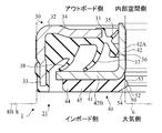
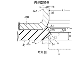
- FIG. 3 It is a partial cross-sectional view of an example of a rolling bearing in which the sealing device which concerns on embodiment of this invention is used. It is a partial cross-sectional view of the sealing device which concerns on embodiment of this invention. It is an enlarged view of a part of FIG. It is an enlarged view similar to FIG. 3 in which the elastic flange portion deformed by the inner member is conspicuous. It is an enlarged sectional view of a part of the sealing device which concerns on a comparative example.
- FIG. 1 shows a hub bearing for an automobile, which is an example of a rolling bearing in which the sealing device according to the embodiment of the present invention is used.
- the application of the present invention is not limited to the hub bearing, and the present invention can be applied to other rolling bearings.
- the hub bearing is a ball bearing, but the application of the present invention is not limited to the ball bearing, and other rolling bearings such as roller bearings and needle bearings having other types of rolling elements.
- the present invention is also applicable.
- the present invention is also applicable to rolling bearings used in machines other than automobiles.
- the hub bearing 1 includes a hub 4 having a hole 2 into which an axle (not shown) is inserted, an inner ring (inner member) 6 attached to the hub 4, and an outer ring (outer side) arranged outside the hub 4. (Member) 8, a plurality of balls 10 arranged in a row between the hub 4 and the outer ring 8, and a plurality of balls 12 arranged in a row between the inner ring 6 and the outer ring 8, and these balls are determined. It has a plurality of cages 14 and 15 for holding in position.
- the common center axis Ax of the axle and the hub bearing 1 extends in the vertical direction in FIG. In FIG. 1, only the left side portion with respect to the central axis Ax is shown.
- the upper side of FIG. 1 is the outside (outboard side) where the wheels of the automobile are arranged, and the lower side is the inside (inboard side) where the differential gears and the like are arranged.
- the outside and the inside shown in FIG. 1 mean the outside and the inside in the radial direction, respectively.
- the outer ring 8 of the hub bearing 1 is fixed to the hub knuckle 16.
- the hub 4 has an outboard side flange 18 projecting radially outward from the outer ring 8. Wheels can be attached to the outboard side flange 18 by means of hub bolts 19.
- a sealing device 20 for sealing the gap between the outer ring 8 and the hub 4 is arranged near the end of the outer ring 8 on the outboard side, and inside the end of the outer ring 8 on the inboard side.
- a sealing device 21 for sealing the gap between the outer ring 8 and the inner ring 6 is arranged.
- the sealing device 20 is arranged between the rotating hub 4 of the hub bearing 1 and the cylindrical end 8A of the fixed outer ring 8 on the outboard side, and seals the gap between the hub 4 and the outer ring 8. Stop.
- the sealing device 21 is arranged between the rotating inner ring 6 of the hub bearing 1 and the end portion 8B on the inboard side of the fixed outer ring 8, and seals the gap between the inner ring 6 and the outer ring 8.
- the sealing device 21 is arranged in the gap between the end portion 8B of the outer ring 8 of the hub bearing 1 on the inboard side and the inner ring 6 of the hub bearing 1.
- the sealing device 21 is annular, only the left side portion thereof is shown in FIG.
- the sealing device 21 has a composite structure including the first sealing member 30 and the second sealing member 40.
- the first seal member 30 is a fixed seal member that is attached to the outer ring 8 and does not rotate.
- the first sealing member 30 is a composite structure having an elastic ring 31 and a rigid ring 32.
- the elastic ring 31 is made of an elastic material, for example, an elastomer.
- the rigid ring 32 is made of a rigid material, for example metal, to reinforce the elastic ring 31.
- the rigid ring 32 has a substantially L-shaped cross-sectional shape. A part of the rigid ring 32 is embedded in the elastic ring 31 and is in close contact with the elastic ring 31.
- the first sealing member 30 has a cylindrical portion 33, an annular portion 34, radial lips 35, 36, and side lips 37, 38.
- the cylindrical portion 33 constitutes a mounting portion to be attached to the outer ring 8. Specifically, the cylindrical portion 33 is fitted (that is, press-fitted) into the end portion 8B of the outer ring 8 by a tightening method.
- the annular portion 34 is an annular shape, is arranged radially inward of the cylindrical portion 33, and extends radially inward toward the inner ring 6.
- the annular portion 34 has a portion having a small thickness located on the inner side in the radial direction and a portion having a large thickness located on the outer side in the radial direction.
- the cylindrical portion 33 and the annular portion 34 are composed of a rigid ring 32 and an elastic ring 31.
- the radial lips 35 and 36 extend radially inward from the inner end of the annular portion 34, and the tips of the radial lips 35 and 36 come into contact with the sleeve 42A of the second sealing member 40.
- the radial lips 35 and 36 are composed of an elastic ring 31.
- the side lip 37 extends from the portion where the thickness of the annular portion 34 is small toward the inboard side.
- the side lip 38 extends from the thick portion of the annular portion 34 toward the inboard side.
- the tips of the side lips 37 and 38 come into contact with the rigid flange portion 42B of the second sealing member 40.
- the side lips 37 and 38 are composed of an elastic ring 31.
- the second seal member 40 can also be referred to as a slinger, that is, a rotary seal member.
- the second seal member 40 is attached to the inner ring 6, and when the inner ring 6 rotates, the second seal member 40 rotates together with the inner ring 6 to repel foreign matter scattered from the outside.
- the second seal member 40 also has a composite structure having an elastic ring 41 and a rigid ring 42.
- the rigid ring 42 is made of a rigid material, for example metal.
- the rigid ring 42 has a substantially L-shaped cross-sectional shape. Specifically, the rigid ring 42 includes a cylindrical sleeve 42A and an annular rigid flange portion 42B extending radially outward from the sleeve 42A.
- the sleeve 42A constitutes a mounting portion to be mounted on the inner ring 6. Specifically, the end portion of the inner ring 6 is fitted (that is, press-fitted) into the sleeve 42A by a tightening method.
- the rigid flange portion 42B is arranged on the radially outer side of the sleeve 42A, extends radially outward, and faces the annular portion 34 of the first seal member 30.
- the rigid flange portion 42B is a flat plate and is in a plane perpendicular to the axis of the sleeve 42A.
- the elastic ring 41 is in close contact with the rigid flange portion 42B of the rigid ring 42.
- the elastic ring 41 is provided to measure the rotational speed of the inner ring 6.
- the elastic ring 41 is made of an elastomer material containing magnetic metal powder and ceramic powder, and has a large number of S poles and N poles depending on the magnetic metal powder.
- a large number of S poles and N poles are alternately arranged at equal intervals in the circumferential direction.
- the rotation angle of the elastic ring 41 can be measured by a magnetic sensor (not shown). Therefore, the magnetic sensor and the elastic ring 41 constitute a magnetic rotary encoder.
- the elastic ring 41 and the rigid flange portion 42B are joined to each other and can be regarded as forming one flange 44. Therefore, the elastic ring 41 can be called an elastic flange portion 45, and the flange 44 is a circle formed of a rigid flange portion 42B made of a rigid material connected to the sleeve 42A and an elastic material in close contact with the rigid flange portion 42B. It can be considered to have an annular elastic flange portion 45.
- the radial lip 35 of the first sealing member 30 is a grease lip.
- the grease lip 35 mainly plays a role of preventing the outflow of the lubricant from the internal space of the hub bearing 1.
- the radial lip 36 is a dust strip.
- the dust strip 36 mainly serves to prevent the inflow of foreign matter from the outside into the internal space of the hub bearing 1.
- the side lips 37 and 38 play a role of blocking the inflow of foreign matter from the outside into the radial lip 36.
- the radial lips 35 and 36 refer to the sleeve 42A of the second seal member 40.
- the side lips 37 and 38 slide with respect to the rigid flange portion 42B of the second sealing member 40.
- an annular protrusion 50 that contacts the outer peripheral surface of the inner ring 6 is formed on the inner circumference of the elastic flange portion 45.
- the inner peripheral surface of the protrusion 50 includes a cylindrical portion 52 and two truncated cone-shaped inclined surface portions 53, 54 adjacent to the cylindrical portion 52.
- the cylindrical portion 52 extends linearly along the axis direction of the second seal member 40 when viewed from the direction perpendicular to the axis of the second seal member 40.
- the inclined surface portion 53 is on the internal space side of the cylindrical portion 52, and the inclined surface portion 54 is on the atmospheric side of the cylindrical portion 52 (between the cylindrical portion 52 and the end surface 45a of the elastic flange portion 45).
- the inner ring 6 and the outer ring 8 are drawn by virtual lines. Since the cylindrical portion 33 of the first sealing member 30 is fitted into the outer ring 8, the cylindrical portion 33 is deformed and is actually located radially inside with respect to FIG. 2. Further, since the inner ring 6 is fitted into the sleeve 42A and the elastic flange portion 45 of the second sealing member 40, the sleeve 42A and the elastic flange portion 45 (particularly, the protrusion 50) are deformed, and are actually shown in FIG. Is also located on the outer side in the radial direction.
- FIG. 2 shows the sleeve 42A in the initial state which is not deformed and the elastic flange portion 45.
- FIG. 3 shows an enlarged view of the sleeve 42A and the elastic flange portion 45 in this initial state.
- FIG. 4 is an enlarged view similar to FIG. 3, but the elastic flange portion 45 (particularly, the protrusion 50) deformed in contact with the inner ring 6 is shown by a solid line, and the protrusion 50 in the initial state is shown by a virtual line. ..
- the sleeve 42A and the inner ring 6 fitted into the sleeve 42A are made of a rigid material, and a minute gap may occur between them. In order to ensure the sealing performance of the internal space sealed by the sealing device 21, it is desirable that the inner peripheral portion of the elastic flange portion 45 is in close contact with the inner ring 6.
- the inner diameter of the cylindrical portion 52 of the protrusion 50 in the initial state is smaller than the inner diameter of the sleeve 42A in order to secure the sealing property of the internal space.
- the difference between the inner radius R1 of the sleeve 42A (see FIG. 3) and the inner radius R2 of the cylindrical portion 52 of the protrusion 50 in the initial state is, for example, 0.1 mm. Therefore, the tightening allowance In2 of the cylindrical portion 52 of the protrusion 50 with respect to the inner ring 6 can be set to be 0.1 mm larger than the tightening allowance In1 of the sleeve 42A with respect to the inner ring 6.
- the length x of the cylindrical portion 52 on the inner peripheral surface of the protrusion 50 is preferably 0.15 mm or more. In this case, even if the pressure in the internal space sealed by the sealing device 21 increases, a gap is unlikely to occur between the protrusion 50 of the elastic flange portion 45 and the cylindrical outer peripheral surface of the inner ring 6. Therefore, the sealing property of the internal space sealed by the sealing device 21 is maintained.
- the length x of the cylindrical portion 52 in the initial state is less than half of the distance D from the end surface 45a (the surface exposed to the atmosphere) of the elastic flange portion 45 to the end 52a of the cylindrical portion 52 on the sleeve 42A side. Is preferable.
- the contact pressure of the protrusion 50 with respect to the outer peripheral surface of the inner ring 6 is high, even if the pressure of the internal space sealed by the sealing device 21 increases, a part of the protrusion 50 is from the end face of the elastic flange portion 45. However, it does not protrude toward the atmosphere, and there is no gap between the protrusion 50 and the outer peripheral surface of the inner ring 6 due to such a large deformation of the protrusion 50.
- FIG. 5 is an enlarged cross-sectional view of a part of the sealing device according to the comparative example. Also in FIG. 5, similarly to FIG. 4, the elastic flange portion 45 (particularly, the protrusion 50) deformed in contact with the inner ring 6 is shown by a solid line, and the protrusion 50 in the initial state is shown by a virtual line. In the comparative example of FIG. 5, the length x of the cylindrical portion 52 in the initial state is larger than half of the distance D from the end surface 45a of the elastic flange portion 45 to the end 52a of the cylindrical portion 52.
- the distance D is 0.65 mm.
- the distance y between the portion where the end surface 45a of the elastic flange portion 45 and the inclined surface portion 54 intersect in the radial direction of the second sealing member 40 and the cylindrical portion 52 is 0.7 mm.
- the angle ⁇ of the truncated cone-shaped inclined surface portion 54 with respect to the end surface 45a is preferably 27 degrees or more and 35 degrees or less.
- the length x of the cylindrical portion 52 in the initial state is 0.3 mm, which is smaller than half of the distance D. Therefore, a part of the protrusion 50 does not protrude toward the atmosphere from the end surface 45a of the elastic flange portion 45.
- the length x of the cylindrical portion 52 in the initial state is 0.16 mm, which is larger than 0.15 mm. Therefore, even if the pressure in the internal space sealed by the sealing device 21 increases, a gap is unlikely to occur between the protrusion 50 of the elastic flange portion 45 and the cylindrical outer peripheral surface of the inner ring 6.
- the hub 4 and the inner ring 6 which are inner members are rotating members
- the outer ring 8 which is an outer member is a stationary member.
- the present invention is not limited to the above embodiment, and can be applied to sealing a plurality of members that rotate relative to each other.
- the inner member may be stationary and the outer member may rotate, or all of these members may rotate.
- the application of the present invention is not limited to sealing the hub bearing 1.
- the differential gear mechanism or other power transmission mechanism of an automobile, the bearing or other support mechanism of a drive shaft of an automobile, the bearing of the rotating shaft of a pump or other support mechanism, etc. are also the sealing device or the sealing structure according to the present invention. Can be used.
- the tips of the side lips 37 and 38 of the first sealing member 30 are brought into contact with the rigid flange portion 42B of the second sealing member 40.
- the side lips 37 and 38 do not have to come into contact with the rigid flange portion 42B.
- the number of side lips is not limited to embodiments. Instead of or in addition to the side lip, a protrusion that promotes the discharge of foreign matter may be provided on the first sealing member 30 or the second sealing member 40.
Landscapes
- Engineering & Computer Science (AREA)
- General Engineering & Computer Science (AREA)
- Mechanical Engineering (AREA)
- Sealing Of Bearings (AREA)
- Sealing With Elastic Sealing Lips (AREA)
- Sealing Devices (AREA)
- Rolling Contact Bearings (AREA)
Priority Applications (4)
| Application Number | Priority Date | Filing Date | Title |
|---|---|---|---|
| DE112021003243.7T DE112021003243T5 (de) | 2020-06-12 | 2021-06-02 | Dichtungsvorrichtung |
| JP2022530501A JP7538225B2 (ja) | 2020-06-12 | 2021-06-02 | 密封装置 |
| US17/925,684 US12013038B2 (en) | 2020-06-12 | 2021-06-02 | Sealing device |
| CN202180040554.2A CN115698563B (zh) | 2020-06-12 | 2021-06-02 | 密封装置 |
Applications Claiming Priority (2)
| Application Number | Priority Date | Filing Date | Title |
|---|---|---|---|
| JP2020-101994 | 2020-06-12 | ||
| JP2020101994 | 2020-06-12 |
Publications (1)
| Publication Number | Publication Date |
|---|---|
| WO2021251232A1 true WO2021251232A1 (ja) | 2021-12-16 |
Family
ID=78846107
Family Applications (1)
| Application Number | Title | Priority Date | Filing Date |
|---|---|---|---|
| PCT/JP2021/020973 Ceased WO2021251232A1 (ja) | 2020-06-12 | 2021-06-02 | 密封装置 |
Country Status (5)
| Country | Link |
|---|---|
| US (1) | US12013038B2 (https=) |
| JP (1) | JP7538225B2 (https=) |
| CN (1) | CN115698563B (https=) |
| DE (1) | DE112021003243T5 (https=) |
| WO (1) | WO2021251232A1 (https=) |
Families Citing this family (1)
| Publication number | Priority date | Publication date | Assignee | Title |
|---|---|---|---|---|
| CN118815832B (zh) * | 2024-09-14 | 2024-11-29 | 南通鑫秀汽车配件有限公司 | 一种汽车轮毂轴承的密封件 |
Citations (6)
| Publication number | Priority date | Publication date | Assignee | Title |
|---|---|---|---|---|
| JPH11304827A (ja) * | 1998-04-22 | 1999-11-05 | Nippon Seiko Kk | エンコーダ付転がり軸受ユニット |
| JP2000289405A (ja) * | 1999-04-02 | 2000-10-17 | Nsk Ltd | エンコーダ付組み合わせシールリング |
| JP2016023755A (ja) * | 2014-07-23 | 2016-02-08 | 日本精工株式会社 | 磁気エンコーダ及び転がり軸受 |
| JP2017026124A (ja) * | 2015-07-28 | 2017-02-02 | 内山工業株式会社 | シール部材 |
| JP2020051601A (ja) * | 2018-09-28 | 2020-04-02 | Ntn株式会社 | 車輪用軸受装置 |
| JP2020144068A (ja) * | 2019-03-08 | 2020-09-10 | 内山工業株式会社 | 磁気エンコーダ及びこれを備えた密封装置 |
Family Cites Families (18)
| Publication number | Priority date | Publication date | Assignee | Title |
|---|---|---|---|---|
| FR2700588B1 (fr) * | 1993-01-19 | 1995-02-17 | Roulements Soc Nouvelle | Dispositif de montage à joint d'étanchéité à codeur incorporé. |
| JP2002139057A (ja) | 2000-11-06 | 2002-05-17 | Koyo Seiko Co Ltd | 転がり軸受ユニットのエンコーダ付密封装置 |
| JP4604388B2 (ja) | 2001-05-09 | 2011-01-05 | 日本精工株式会社 | エンコーダ付組み合わせシールリングを備えた転がり軸受ユニット |
| ITTO20020221A1 (it) | 2002-03-14 | 2003-09-15 | Skf Ind Spa | Dispositivo di tenuta per cuscinetti a rotolamento. |
| JP4058558B2 (ja) * | 2004-03-31 | 2008-03-12 | 杉晃 草竹 | パッキンとその装着方法 |
| JP5430026B2 (ja) * | 2009-07-02 | 2014-02-26 | 内山工業株式会社 | 嵌合部の密封構造 |
| CN202896176U (zh) * | 2011-10-05 | 2013-04-24 | 日本精工株式会社 | 轮毂单元 |
| JP5853563B2 (ja) * | 2011-10-05 | 2016-02-09 | 日本精工株式会社 | エンコーダ及び組み合わせシールリング付ハブユニットの製造方法 |
| DE102011088865A1 (de) | 2011-12-16 | 2013-06-20 | Schaeffler Technologies AG & Co. KG | Signalgeberring mit Schräge |
| DE102012204620B4 (de) | 2012-03-22 | 2020-08-13 | Schaeffler Technologies AG & Co. KG | Kassettendichtung, insbesondere für eine Radlageranordnung eines Kraftfahrzeuges, und eine Radlageranordnung mit einer solchen Kassettendichtung |
| FR2995961B1 (fr) * | 2012-09-26 | 2014-10-17 | Joint Francais | Joint annulaire, et moule de fabrication d'un tel joint. |
| EP2962018B1 (en) * | 2013-02-27 | 2019-05-22 | Hendrickson USA, L.L.C. | Main seal for a heavy-duty vehicle wheel-end assembly |
| WO2016181515A1 (ja) | 2015-05-12 | 2016-11-17 | 日本精工株式会社 | 磁気エンコーダ及び転がり軸受 |
| JP2017190804A (ja) | 2016-04-12 | 2017-10-19 | Nok株式会社 | 密封装置 |
| IT201600070543A1 (it) * | 2016-07-06 | 2018-01-06 | Rolf S P A | Complesso di tenuta a cassetta, in particolare per assali di veicoli |
| CN113979962A (zh) | 2017-03-31 | 2022-01-28 | 先正达参股股份有限公司 | 杀真菌组合物 |
| JP6960818B2 (ja) * | 2017-10-05 | 2021-11-05 | Nok株式会社 | 密封装置 |
| JP6684340B2 (ja) * | 2018-12-19 | 2020-04-22 | パラマウントベッド株式会社 | エアマットレス及びエアマットレスにおける制御方法 |
-
2021
- 2021-06-02 CN CN202180040554.2A patent/CN115698563B/zh active Active
- 2021-06-02 WO PCT/JP2021/020973 patent/WO2021251232A1/ja not_active Ceased
- 2021-06-02 DE DE112021003243.7T patent/DE112021003243T5/de active Pending
- 2021-06-02 JP JP2022530501A patent/JP7538225B2/ja active Active
- 2021-06-02 US US17/925,684 patent/US12013038B2/en active Active
Patent Citations (6)
| Publication number | Priority date | Publication date | Assignee | Title |
|---|---|---|---|---|
| JPH11304827A (ja) * | 1998-04-22 | 1999-11-05 | Nippon Seiko Kk | エンコーダ付転がり軸受ユニット |
| JP2000289405A (ja) * | 1999-04-02 | 2000-10-17 | Nsk Ltd | エンコーダ付組み合わせシールリング |
| JP2016023755A (ja) * | 2014-07-23 | 2016-02-08 | 日本精工株式会社 | 磁気エンコーダ及び転がり軸受 |
| JP2017026124A (ja) * | 2015-07-28 | 2017-02-02 | 内山工業株式会社 | シール部材 |
| JP2020051601A (ja) * | 2018-09-28 | 2020-04-02 | Ntn株式会社 | 車輪用軸受装置 |
| JP2020144068A (ja) * | 2019-03-08 | 2020-09-10 | 内山工業株式会社 | 磁気エンコーダ及びこれを備えた密封装置 |
Also Published As
| Publication number | Publication date |
|---|---|
| CN115698563A (zh) | 2023-02-03 |
| DE112021003243T5 (de) | 2023-04-06 |
| JP7538225B2 (ja) | 2024-08-21 |
| US20230193998A1 (en) | 2023-06-22 |
| US12013038B2 (en) | 2024-06-18 |
| JPWO2021251232A1 (https=) | 2021-12-16 |
| CN115698563B (zh) | 2026-02-03 |
Similar Documents
| Publication | Publication Date | Title |
|---|---|---|
| US10900524B2 (en) | Sealing member, and bearing device for vehicle wheel comprising same | |
| CN113939663B (zh) | 密封装置 | |
| US8016294B2 (en) | Sealing device | |
| JP7524804B2 (ja) | 転がり軸受装置 | |
| CN107407336B (zh) | 车辆用车轮轴承单元 | |
| US20220333649A1 (en) | Sealing device | |
| WO2020045072A1 (ja) | シール部材の製造方法および成形型 | |
| JP7538225B2 (ja) | 密封装置 | |
| US12152636B2 (en) | Sealing device | |
| JP6985881B2 (ja) | 車輪用軸受装置 | |
| JP7458198B2 (ja) | 密封装置および密封構造 | |
| JP2022156566A (ja) | 車輪用軸受装置 | |
| JP7175170B2 (ja) | 密封装置 | |
| JP2009127668A (ja) | 密封装置 | |
| JP7011716B2 (ja) | 密封装置 | |
| JP7390131B2 (ja) | 密封装置および密封構造 | |
| JP7723087B2 (ja) | 密封装置 | |
| JP7341778B2 (ja) | 密封装置および密封構造 | |
| JP7344697B2 (ja) | 密封装置および密封構造 | |
| JP2019184043A (ja) | ハブユニット軸受 | |
| WO2023189756A1 (ja) | 車輪用軸受装置 | |
| JP2024063987A (ja) | 車輪用軸受装置 | |
| JP2022048883A (ja) | 密封装置 | |
| JP2026028345A (ja) | ハブユニット軸受 | |
| JP2020027077A (ja) | 磁気エンコーダ |
Legal Events
| Date | Code | Title | Description |
|---|---|---|---|
| 121 | Ep: the epo has been informed by wipo that ep was designated in this application |
Ref document number: 21821617 Country of ref document: EP Kind code of ref document: A1 |
|
| ENP | Entry into the national phase |
Ref document number: 2022530501 Country of ref document: JP Kind code of ref document: A |
|
| 122 | Ep: pct application non-entry in european phase |
Ref document number: 21821617 Country of ref document: EP Kind code of ref document: A1 |