WO2021251116A1 - 表示システム - Google Patents
表示システム Download PDFInfo
- Publication number
- WO2021251116A1 WO2021251116A1 PCT/JP2021/019532 JP2021019532W WO2021251116A1 WO 2021251116 A1 WO2021251116 A1 WO 2021251116A1 JP 2021019532 W JP2021019532 W JP 2021019532W WO 2021251116 A1 WO2021251116 A1 WO 2021251116A1
- Authority
- WO
- WIPO (PCT)
- Prior art keywords
- correction
- display
- processing
- vibration
- image correction
- Prior art date
- Legal status (The legal status is an assumption and is not a legal conclusion. Google has not performed a legal analysis and makes no representation as to the accuracy of the status listed.)
- Ceased
Links
Images













Classifications
-
- G—PHYSICS
- G02—OPTICS
- G02B—OPTICAL ELEMENTS, SYSTEMS OR APPARATUS
- G02B27/00—Optical systems or apparatus not provided for by any of the groups G02B1/00 - G02B26/00, G02B30/00
- G02B27/01—Head-up displays
- G02B27/0101—Head-up displays characterised by optical features
-
- B—PERFORMING OPERATIONS; TRANSPORTING
- B60—VEHICLES IN GENERAL
- B60K—ARRANGEMENT OR MOUNTING OF PROPULSION UNITS OR OF TRANSMISSIONS IN VEHICLES; ARRANGEMENT OR MOUNTING OF PLURAL DIVERSE PRIME-MOVERS IN VEHICLES; AUXILIARY DRIVES FOR VEHICLES; INSTRUMENTATION OR DASHBOARDS FOR VEHICLES; ARRANGEMENTS IN CONNECTION WITH COOLING, AIR INTAKE, GAS EXHAUST OR FUEL SUPPLY OF PROPULSION UNITS IN VEHICLES
- B60K35/00—Instruments specially adapted for vehicles; Arrangement of instruments in or on vehicles
- B60K35/10—Input arrangements, i.e. from user to vehicle, associated with vehicle functions or specially adapted therefor
-
- B—PERFORMING OPERATIONS; TRANSPORTING
- B60—VEHICLES IN GENERAL
- B60K—ARRANGEMENT OR MOUNTING OF PROPULSION UNITS OR OF TRANSMISSIONS IN VEHICLES; ARRANGEMENT OR MOUNTING OF PLURAL DIVERSE PRIME-MOVERS IN VEHICLES; AUXILIARY DRIVES FOR VEHICLES; INSTRUMENTATION OR DASHBOARDS FOR VEHICLES; ARRANGEMENTS IN CONNECTION WITH COOLING, AIR INTAKE, GAS EXHAUST OR FUEL SUPPLY OF PROPULSION UNITS IN VEHICLES
- B60K35/00—Instruments specially adapted for vehicles; Arrangement of instruments in or on vehicles
- B60K35/20—Output arrangements, i.e. from vehicle to user, associated with vehicle functions or specially adapted therefor
- B60K35/21—Output arrangements, i.e. from vehicle to user, associated with vehicle functions or specially adapted therefor using visual output, e.g. blinking lights or matrix displays
- B60K35/22—Display screens
-
- B—PERFORMING OPERATIONS; TRANSPORTING
- B60—VEHICLES IN GENERAL
- B60K—ARRANGEMENT OR MOUNTING OF PROPULSION UNITS OR OF TRANSMISSIONS IN VEHICLES; ARRANGEMENT OR MOUNTING OF PLURAL DIVERSE PRIME-MOVERS IN VEHICLES; AUXILIARY DRIVES FOR VEHICLES; INSTRUMENTATION OR DASHBOARDS FOR VEHICLES; ARRANGEMENTS IN CONNECTION WITH COOLING, AIR INTAKE, GAS EXHAUST OR FUEL SUPPLY OF PROPULSION UNITS IN VEHICLES
- B60K35/00—Instruments specially adapted for vehicles; Arrangement of instruments in or on vehicles
- B60K35/20—Output arrangements, i.e. from vehicle to user, associated with vehicle functions or specially adapted therefor
- B60K35/21—Output arrangements, i.e. from vehicle to user, associated with vehicle functions or specially adapted therefor using visual output, e.g. blinking lights or matrix displays
- B60K35/23—Head-up displays [HUD]
-
- B—PERFORMING OPERATIONS; TRANSPORTING
- B60—VEHICLES IN GENERAL
- B60K—ARRANGEMENT OR MOUNTING OF PROPULSION UNITS OR OF TRANSMISSIONS IN VEHICLES; ARRANGEMENT OR MOUNTING OF PLURAL DIVERSE PRIME-MOVERS IN VEHICLES; AUXILIARY DRIVES FOR VEHICLES; INSTRUMENTATION OR DASHBOARDS FOR VEHICLES; ARRANGEMENTS IN CONNECTION WITH COOLING, AIR INTAKE, GAS EXHAUST OR FUEL SUPPLY OF PROPULSION UNITS IN VEHICLES
- B60K35/00—Instruments specially adapted for vehicles; Arrangement of instruments in or on vehicles
- B60K35/20—Output arrangements, i.e. from vehicle to user, associated with vehicle functions or specially adapted therefor
- B60K35/28—Output arrangements, i.e. from vehicle to user, associated with vehicle functions or specially adapted therefor characterised by the type of the output information, e.g. video entertainment or vehicle dynamics information; characterised by the purpose of the output information, e.g. for attracting the attention of the driver
-
- B—PERFORMING OPERATIONS; TRANSPORTING
- B60—VEHICLES IN GENERAL
- B60K—ARRANGEMENT OR MOUNTING OF PROPULSION UNITS OR OF TRANSMISSIONS IN VEHICLES; ARRANGEMENT OR MOUNTING OF PLURAL DIVERSE PRIME-MOVERS IN VEHICLES; AUXILIARY DRIVES FOR VEHICLES; INSTRUMENTATION OR DASHBOARDS FOR VEHICLES; ARRANGEMENTS IN CONNECTION WITH COOLING, AIR INTAKE, GAS EXHAUST OR FUEL SUPPLY OF PROPULSION UNITS IN VEHICLES
- B60K35/00—Instruments specially adapted for vehicles; Arrangement of instruments in or on vehicles
- B60K35/80—Arrangements for controlling instruments
- B60K35/81—Arrangements for controlling instruments for controlling displays
-
- B—PERFORMING OPERATIONS; TRANSPORTING
- B60—VEHICLES IN GENERAL
- B60R—VEHICLES, VEHICLE FITTINGS, OR VEHICLE PARTS, NOT OTHERWISE PROVIDED FOR
- B60R11/00—Arrangements for holding or mounting articles, not otherwise provided for
- B60R11/02—Arrangements for holding or mounting articles, not otherwise provided for for radio sets, television sets, telephones, or the like; Arrangement of controls thereof
-
- G—PHYSICS
- G09—EDUCATION; CRYPTOGRAPHY; DISPLAY; ADVERTISING; SEALS
- G09G—ARRANGEMENTS OR CIRCUITS FOR CONTROL OF INDICATING DEVICES USING STATIC MEANS TO PRESENT VARIABLE INFORMATION
- G09G5/00—Control arrangements or circuits for visual indicators common to cathode-ray tube indicators and other visual indicators
-
- G—PHYSICS
- G09—EDUCATION; CRYPTOGRAPHY; DISPLAY; ADVERTISING; SEALS
- G09G—ARRANGEMENTS OR CIRCUITS FOR CONTROL OF INDICATING DEVICES USING STATIC MEANS TO PRESENT VARIABLE INFORMATION
- G09G5/00—Control arrangements or circuits for visual indicators common to cathode-ray tube indicators and other visual indicators
- G09G5/36—Control arrangements or circuits for visual indicators common to cathode-ray tube indicators and other visual indicators characterised by the display of a graphic pattern, e.g. using an all-points-addressable [APA] memory
- G09G5/38—Control arrangements or circuits for visual indicators common to cathode-ray tube indicators and other visual indicators characterised by the display of a graphic pattern, e.g. using an all-points-addressable [APA] memory with means for controlling the display position
-
- H—ELECTRICITY
- H04—ELECTRIC COMMUNICATION TECHNIQUE
- H04N—PICTORIAL COMMUNICATION, e.g. TELEVISION
- H04N5/00—Details of television systems
- H04N5/74—Projection arrangements for image reproduction, e.g. using eidophor
-
- B—PERFORMING OPERATIONS; TRANSPORTING
- B60—VEHICLES IN GENERAL
- B60K—ARRANGEMENT OR MOUNTING OF PROPULSION UNITS OR OF TRANSMISSIONS IN VEHICLES; ARRANGEMENT OR MOUNTING OF PLURAL DIVERSE PRIME-MOVERS IN VEHICLES; AUXILIARY DRIVES FOR VEHICLES; INSTRUMENTATION OR DASHBOARDS FOR VEHICLES; ARRANGEMENTS IN CONNECTION WITH COOLING, AIR INTAKE, GAS EXHAUST OR FUEL SUPPLY OF PROPULSION UNITS IN VEHICLES
- B60K2360/00—Indexing scheme associated with groups B60K35/00 or B60K37/00 relating to details of instruments or dashboards
- B60K2360/16—Type of output information
- B60K2360/167—Vehicle dynamics information
-
- B—PERFORMING OPERATIONS; TRANSPORTING
- B60—VEHICLES IN GENERAL
- B60K—ARRANGEMENT OR MOUNTING OF PROPULSION UNITS OR OF TRANSMISSIONS IN VEHICLES; ARRANGEMENT OR MOUNTING OF PLURAL DIVERSE PRIME-MOVERS IN VEHICLES; AUXILIARY DRIVES FOR VEHICLES; INSTRUMENTATION OR DASHBOARDS FOR VEHICLES; ARRANGEMENTS IN CONNECTION WITH COOLING, AIR INTAKE, GAS EXHAUST OR FUEL SUPPLY OF PROPULSION UNITS IN VEHICLES
- B60K2360/00—Indexing scheme associated with groups B60K35/00 or B60K37/00 relating to details of instruments or dashboards
- B60K2360/20—Optical features of instruments
- B60K2360/33—Illumination features
- B60K2360/334—Projection means
-
- B—PERFORMING OPERATIONS; TRANSPORTING
- B60—VEHICLES IN GENERAL
- B60K—ARRANGEMENT OR MOUNTING OF PROPULSION UNITS OR OF TRANSMISSIONS IN VEHICLES; ARRANGEMENT OR MOUNTING OF PLURAL DIVERSE PRIME-MOVERS IN VEHICLES; AUXILIARY DRIVES FOR VEHICLES; INSTRUMENTATION OR DASHBOARDS FOR VEHICLES; ARRANGEMENTS IN CONNECTION WITH COOLING, AIR INTAKE, GAS EXHAUST OR FUEL SUPPLY OF PROPULSION UNITS IN VEHICLES
- B60K2360/00—Indexing scheme associated with groups B60K35/00 or B60K37/00 relating to details of instruments or dashboards
- B60K2360/77—Instrument locations other than the dashboard
- B60K2360/785—Instrument locations other than the dashboard on or in relation to the windshield or windows
-
- B—PERFORMING OPERATIONS; TRANSPORTING
- B60—VEHICLES IN GENERAL
- B60K—ARRANGEMENT OR MOUNTING OF PROPULSION UNITS OR OF TRANSMISSIONS IN VEHICLES; ARRANGEMENT OR MOUNTING OF PLURAL DIVERSE PRIME-MOVERS IN VEHICLES; AUXILIARY DRIVES FOR VEHICLES; INSTRUMENTATION OR DASHBOARDS FOR VEHICLES; ARRANGEMENTS IN CONNECTION WITH COOLING, AIR INTAKE, GAS EXHAUST OR FUEL SUPPLY OF PROPULSION UNITS IN VEHICLES
- B60K35/00—Instruments specially adapted for vehicles; Arrangement of instruments in or on vehicles
- B60K35/60—Instruments characterised by their location or relative disposition in or on vehicles
-
- G—PHYSICS
- G02—OPTICS
- G02B—OPTICAL ELEMENTS, SYSTEMS OR APPARATUS
- G02B27/00—Optical systems or apparatus not provided for by any of the groups G02B1/00 - G02B26/00, G02B30/00
- G02B27/01—Head-up displays
- G02B27/0101—Head-up displays characterised by optical features
- G02B2027/011—Head-up displays characterised by optical features comprising device for correcting geometrical aberrations, distortion
-
- G—PHYSICS
- G02—OPTICS
- G02B—OPTICAL ELEMENTS, SYSTEMS OR APPARATUS
- G02B27/00—Optical systems or apparatus not provided for by any of the groups G02B1/00 - G02B26/00, G02B30/00
- G02B27/01—Head-up displays
- G02B27/0101—Head-up displays characterised by optical features
- G02B2027/014—Head-up displays characterised by optical features comprising information/image processing systems
Definitions
- the present disclosure relates to a display system that controls the display position of display content according to the movement of a moving object.
- Patent Document 1 discloses a vehicle information projection system that performs augmented reality (AR) display using a head-up display (HUD) device.
- the HUD device projects a light representing a virtual image onto the windshield of the vehicle so that the viewer, who is a occupant of the vehicle, can see the virtual image together with the actual view of the outside world of the vehicle.
- a virtual image representing a vehicle guidance route is displayed in association with a display target (for example, a road) in the actual scene.
- a display target for example, a road
- the vehicle information projection system described in Patent Document 1 includes a vehicle speed sensor and corrects the display position of a virtual image according to the acceleration. As a result, it is possible to prevent the virtual image from being displaced during sudden deceleration and sudden acceleration of the vehicle.
- the present disclosure provides a display system that suppresses misalignment of the display position of display content.
- the display system of the present disclosure has a display processing device that controls the display of the display content, an image correction unit that performs image correction processing that changes the display position of the display content based on the image correction data stored in advance, and a movement.
- An attitude detection device that detects the amount of change in body posture, a vibration correction processing device that calculates the amount of vibration correction for the display position of the displayed content based on the amount of change in the posture of the moving object, and an image that involves changing the display position of the displayed content.
- the display processing device includes a processing switching unit that switches the processing order of the correction processing, the vibration correction processing that corrects the display position of the displayed content based on the vibration correction amount, and the processing switched by the processing switching unit.
- the display position of the displayed content is controlled by performing the image correction process and the vibration correction process based on the order of.
- the display system of the present disclosure it is possible to suppress the misalignment of the display position of the displayed content.
- a diagram for explaining a head-up display A block diagram showing the internal configuration of the display system according to the first embodiment. Diagram showing an example when the vehicle is not tilted A diagram showing an example of a real scene seen from the windshield The figure which shows the example which the display content is displayed in a reference position. Diagram showing an example of augmented reality (AR) display Diagram showing the backward leaning posture of the vehicle A diagram for explaining an example in which the displayed content is misaligned when the vehicle is in a backward leaning posture.
- AR augmented reality
- FIG. 14A (a) shows the offset error of the fluctuation amount
- FIG. 14A (b) is the explanatory diagram which shows the fluctuation amount which the offset error was removed.
- FIG. 14B (a) shows an example of the vibration of the fluctuation amount
- FIG. 14B (b) is the explanatory diagram which shows the counted flag.
- a block diagram showing the internal configuration of the display system according to the third embodiment. A diagram showing an example of the initial position of the display content Figure showing another example of the initial position of the display content The figure which shows the example which the image correction error occurs when the vibration correction processing is performed after the image correction processing.
- Flow chart showing display processing in the fifth embodiment A flowchart showing the calculation process of the vibration correction amount in the fifth embodiment.
- the display position of the display content (for example, arrow, figure, character, etc.) displayed in the display area is electronically corrected according to the state (for example, posture) of the moving object detected based on the output of the sensor. It is known to do.
- the display system performs vibration correction processing that corrects the display position of the displayed content based on the vibration of the moving body detected by the sensor.
- the displayed image when the display content is displayed in the display area, the displayed image may be distorted or rotated.
- the display content when the display content is displayed in front of the windshield of a moving vehicle, the display content may be distorted when the display content is reflected by the windshield.
- the displayed content may be displayed at an angle due to variations in the manufacturing of the display system. Therefore, in the display system, in order to correct distortion and rotation deviation of the display content, an image correction process for changing the display position of the display content is performed.
- the display system acquires information such as distortion and rotation deviation when the displayed content is displayed in the display area at the time of manufacturing or design, and stores the image correction data calculated based on the information in the storage unit. Keep it.
- the image correction data includes information on a correction value that corrects a deviation in the display position of the display content such as distortion and rotation deviation.
- the display system corrects distortion, rotation deviation, and the like by performing image correction processing based on image correction data stored in advance in the storage unit.
- the order of processing is fixed and vibration correction processing and image correction processing are performed.
- a display system that performs image correction processing after performing vibration correction processing will be described.
- the delay time from the completion of changing the display position of the display content by the vibration correction processing to the display becomes long.
- the allowable delay time is shortened in order to suppress the following. As a result, the vibration correction error increases, and the correction accuracy of the vibration correction process decreases. It is effective to reduce the delay time in order to suppress the deterioration of the correction accuracy.
- the processing time of the image correction processing is long or high frequency vibration is generated, it is conceivable to perform the vibration correction processing after performing the image correction processing as one method for reducing the delay time. ..
- the accuracy of the image correction is higher when the image correction process is performed after the vibration correction process is performed. If the vibration correction process is always performed after the image correction process is performed, it becomes difficult to improve the correction accuracy of the image correction.
- the processing time of the image correction processing is short or high frequency vibration is not generated, the effect of improving the accuracy of the vibration correction is small even if the vibration correction processing is performed after the image correction processing is performed. Therefore, when the processing time of the image correction processing is short or high frequency vibration is not generated, the correction accuracy of the image correction can be improved by performing the image correction processing after performing the vibration correction processing.
- the present inventors have found that the order of processing between vibration correction processing and image correction processing is switched in order to solve the above-mentioned problems. For example, when the processing time of the image correction processing is long, the display content is displayed from the completion of the change of the display position of the display content by the vibration correction processing by switching the processing order so that the vibration correction processing is performed after the image correction processing is performed. The delay time until can be shortened. As a result, the vibration correction error can be reduced and the deterioration of the correction accuracy of the display position of the displayed content can be suppressed.
- the display system of the present disclosure switches the order of processing between vibration correction processing and image correction processing according to the traveling condition of a moving object, the processing time of image correction processing, and the like. As a result, it is possible to suppress a decrease in the correction accuracy of the display content. As a result, it is possible to suppress the positional deviation of the display position of the display content.
- the moving body is a vehicle such as an automobile and the display system is a head-up display (HUD) system for displaying display contents in front of the windshield of the vehicle will be described as an example.
- HUD head-up display
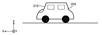
- FIG. 1 is a diagram for explaining the HUD system.
- the roll axis of the vehicle 200 is the X axis
- the pitch axis of the vehicle 200 is the Y axis
- the yaw axis of the vehicle 200 is the Z axis. That is, the X-axis is orthogonal to the Y-axis and the Z-axis, and is an axis along the line-of-sight direction of the occupant D who visually recognizes the displayed content Iv.
- the Y-axis is an axis along the left-right direction when viewed from the occupant D who visually recognizes the displayed content Iv.
- the Z axis is an axis along the height direction of the vehicle 200.
- the display system 100 of the present embodiment is a so-called augmented reality (AR) display in which the display content Iv is superimposed on the actual view in front of the windshield 210 of the vehicle 200.
- the display content Iv is content indicating predetermined information displayed in the display area 220.
- the display content Iv is a figure and characters indicating a route for guiding to a destination, an estimated time of arrival at the destination, a traveling direction, a speed, various warnings, and the like.
- an arrow indicating a route for guiding to the destination will be described as an example of the display content Iv.
- the display system 100 is installed in the vehicle 200 and projects the display light Lc representing the display content Iv into the display area 220 of the windshield 210 of the vehicle 200.
- the display area 220 is a part of the windshield 210.
- the display area 220 may be the entire area of the windshield 210.
- the display light Lc is reflected in the vehicle interior direction by the windshield 210. As a result, the occupant D in the vehicle 200 visually recognizes the reflected display light Lc as the display content Iv in front of the vehicle 200.
- the display system 100 includes a projection device 10, an information acquisition device 20, a display processing device 30, a posture detection device 40, and a vibration correction processing device 50.
- the projection device 10 projects the display light Lc representing the display content Iv into the display area 220.
- the projection device 10 includes, for example, a liquid crystal display element that displays an image of display content Iv, a light source such as an LED that illuminates the liquid crystal display element, a mirror that reflects the display light Lc of the image displayed by the liquid crystal display element to the display area 220, and a mirror. Including lenses and the like.
- the projection device 10 is installed, for example, in the dashboard of the vehicle 200.
- the information acquisition device 20 acquires information indicating the position of the vehicle 200. Specifically, the information acquisition device 20 measures the position of the vehicle 200 and generates position information indicating the position. The information acquisition device 20 outputs vehicle-related information including the position information of the vehicle 200.
- the display processing device 30 controls the display of the display content Iv based on the vehicle-related information obtained from the information acquisition device 20, and outputs the image data of the display content Iv to the projection device 10.
- the display processing device 30 may control the display of the display content Iv based on the display timing (display time) of the display content Iv or the combination of the vehicle-related information and the display timing.
- the display timing is, for example, repeating display for 10 seconds and non-display for 1 second.
- the display processing device 30 performs image correction processing accompanied by changing the display position of the display content Iv based on the image correction data, and corrects the display deviation such as distortion and rotation deviation of the display content Iv.
- the posture detection device 40 detects the posture change of the vehicle 200. Specifically, the posture detecting device 40 detects the amount of change in the posture of the vehicle 200.
- the amount of change in attitude is the angular velocity.
- the attitude detection device 40 includes, for example, a gyro sensor 41 (see FIG. 2) that detects an angular velocity.
- the gyro sensor 41 outputs the detected angular velocity to the vibration correction processing device 50 as a posture change amount indicating the posture change of the vehicle 200.
- the vibration correction processing device 50 calculates the vibration correction amount of the display position of the display content Iv based on the posture change of the vehicle 200 detected by the posture detection device 40.
- the vibration correction processing device 50 outputs the calculated vibration correction amount to the display processing device 30.
- the display position of the display content Iv is corrected in the display area 220 according to the change in the actual view seen from the windshield 210.
- FIG. 2 is a block diagram showing the internal configuration of the display system 100.
- the information acquisition device 20 includes a GPS (Global Positioning System) module 21 that detects a position indicating the current location of the vehicle 200 in the geographic coordinate system. Specifically, the GPS module 21 receives radio waves from GPS satellites and determines the latitude and longitude of the received points. The GPS module 21 generates position information indicating the measured latitude and longitude. The information acquisition device 20 outputs vehicle-related information including position information to the display processing device 30.
- GPS Global Positioning System
- the display processing device 30 includes a communication unit 31, a display control unit 32, a storage unit 33, and an image correction unit 34.
- the communication unit 31 includes a circuit that communicates with an external device in accordance with a predetermined communication standard.
- Predetermined communication standards include, for example, LAN, Wi-Fi (registered trademark), Bluetooth (registered trademark), USB, HDMI (registered trademark), CAN (controller area network), SPI (Serial Peripheral Interface).
- the display control unit 32 can be realized by a semiconductor element or the like.
- the display control unit 32 can be composed of, for example, a microcomputer, a CPU, an MPU, a GPU, a DSP, an FPGA, and an ASIC.
- the function of the display control unit 32 may be configured only by hardware, or may be realized by combining hardware and software.
- the display control unit 32 realizes a predetermined function by reading data and programs stored in the storage unit 33 and performing various arithmetic processes.
- the display control unit 32 includes a processing switching unit 32a.
- the process switching unit 32a switches the order of processing between the image correction process and the vibration correction process.
- the image correction process is an image correction accompanied by a change in the display position of the display content Iv performed by the image correction unit 34.
- the vibration correction processing is a vibration correction that corrects the display position of the display content Iv based on the vibration correction amount calculated by the vibration correction processing device 50.
- the process switching unit 32a switches the order of processing between the image correction process and the vibration correction process based on a predetermined condition.
- the processing switching unit 32a acquires the image processing time Td of the image correction processing, and switches the order of processing between the image correction processing and the vibration correction processing based on the image processing time Td.
- the image processing time Td means the processing time required for changing the display position of the display content Iv by the image correction processing.
- the image processing time Td may be a predetermined value or a value that changes for each image correction processing target.
- the image processing time Td may be calculated based on the amount of information and / or the image correction value U of the display content Iv on which the image correction processing is performed.
- the processing switching unit 32a switches the order of processing so that the image correction processing is performed after the vibration correction processing is performed. Further, when the image processing time Td is larger than the first threshold value T1, the processing switching unit 32a switches the order of processing so that the vibration correction processing is performed after the image correction processing is performed.
- the storage unit 33 is a storage medium for storing programs and data necessary for realizing the functions of the display processing device 30.
- the storage unit 33 can be realized by, for example, a hard disk (HDD), SSD, RAM, DRAM, ferroelectric memory, flash memory, magnetic disk, or a combination thereof.
- the storage unit 33 stores a plurality of image data 33i representing the display content Iv. Further, the storage unit 33 stores the image correction data 33g used for the image correction processing.
- the image correction data 33g includes, for example, an image correction value for correcting display deviation such as distortion and / or rotation deviation of an image representing display content Iv.
- the image correction value is known data calculated based on, for example, image distortion and / or rotation deviation measured by inspection at the time of manufacture of the display system 100, and is a static value.
- the distortion is, for example, distortion that occurs when the display content Iv is reflected by the windshield 210 when the display content Iv is displayed in front of the windshield 210 of the vehicle 200.
- the rotation deviation is a deviation caused by a variation in installation, for example, when the projection device 10 is installed at an angle with respect to the windshield 210 on which light is projected from the projection device 10.
- the image correction data 33g may divide the display area 220 into a plurality of division areas and store the image correction value assigned to each of the plurality of division areas.
- the image correction data 33g may store an image correction table showing image correction values assigned to each of the plurality of partition areas.
- the image correction data 33g may include an image correction value for correcting a display deviation that causes a change in the display position of the display content Iv other than distortion and / or rotation deviation.
- the image correction unit 34 performs image correction processing accompanied by a change in the display position of the display content Iv based on the image correction data 33g stored in advance in the storage unit 33.
- the image correction process accompanied by the change of the display position of the display content Iv includes, for example, correction of distortion of the image and / or correction of rotation deviation of the image.
- the image correction unit 34 corrects distortion and / or rotation deviation of the display content Iv projected on the windshield 210 of the vehicle 200 by the projection device 10.
- the image correction unit 34 reads out the image correction data 33g stored in advance in the storage unit 33, and determines an image correction value for correcting the display deviation of the display position of the display content Iv caused by distortion and / or rotation deviation. ..
- the image correction unit 34 determines the image correction value using the image correction table of the image correction data 33g.
- the image correction value determined by the image correction unit 34 is output to the display control unit 32.
- the image correction unit 34 may be included in the display control unit 32.
- the display control unit 32 determines the display content Iv to be displayed in the display area 220 based on the vehicle-related information obtained from the information acquisition device 20.
- the display control unit 32 reads the image data 33i of the determined display content Iv from the storage unit 33 and outputs the image data 33i to the projection device 10.
- the display control unit 32 acquires information indicating the display reference position from an external device (not shown) via the communication unit 31.
- the display reference position is a position that serves as a reference for displaying the display content Iv in the display area 220.
- the display control unit 32 acquires content information indicating information on the display content Iv.
- the content information includes, for example, information such as the shape, size, display edge, and display reference position of the display content Iv.
- information on display content including display reference position and content information (for example, information such as size of display content) is referred to as content display information.
- the content display information includes at least a feature portion that determines the shape of the displayed content.
- the feature portion is, for example, a pixel position of a content display.
- the content display information is stored in the storage unit 33 together with the image data 33i.
- the display control unit 32 acquires vehicle-related information from the information acquisition device 20 via the communication unit 31, and uses the images to be used among the plurality of image data 33i stored in the storage unit 33 based on the vehicle-related information. Determine the data. As a result, the display control unit 32 acquires information indicating the shape, size, display end, and the like of the display content Iv.
- the display control unit 32 outputs the content display information to the vibration correction processing device 50.
- the display control unit 32 acquires the image correction value of the display content Iv from the image correction unit 34, and changes the display position of the display content Iv based on the image correction value. Further, the display control unit 32 acquires the vibration correction amount from the vibration correction processing device 50. The display control unit 32 sets the display position of the display content Iv based on the display reference position and the vibration correction amount.
- the attitude detection device 40 includes a gyro sensor 41 that detects an angular velocity.
- the gyro sensor 41 outputs the detected angular velocity to the vibration correction processing device 50 as a posture change amount indicating the posture change of the vehicle 200.
- the calculation processing of the output of the posture detection device 40 may be performed by the deviation amount calculation unit 52a of the posture detection device 40 or the vibration correction processing device 50, or another configuration.
- the vibration correction processing device 50 includes a communication unit 51, a correction control unit 52, and a storage unit 53.
- the communication unit 51 includes a circuit that communicates with an external device in accordance with a predetermined communication standard.
- Predetermined communication standards include, for example, LAN, Wi-Fi (registered trademark), Bluetooth (registered trademark), USB, HDMI (registered trademark), CAN (controller area network), SPI (Serial Peripheral Interface).
- the correction control unit 52 can be realized by a semiconductor element or the like.
- the correction control unit 52 can be composed of, for example, a microcomputer, a CPU, an MPU, a GPU, a DSP, an FPGA, and an ASIC.
- the function of the display control unit 32 may be configured only by hardware, or may be realized by combining hardware and software.
- the correction control unit 52 realizes a predetermined function by reading data or a program stored in a storage unit (not shown) in the vibration correction processing device 50 and performing various arithmetic processing.
- the correction control unit 52 includes a deviation amount calculation unit 52a and a correction amount calculation unit 52b as functional configurations.
- the deviation amount calculation unit 52a calculates the attitude (angle deviation amount) of the vehicle 200 based on the attitude change amount output by the attitude detection device 40.
- the amount of deviation of the angle is the posture angle with respect to the posture state that is the reference of the moving body.
- the reference posture state of the moving body is, for example, a stationary vehicle state placed in a horizontal state.
- the deviation amount calculation unit 52a calculates the angle (pitch angle) around the pitch axis of the vehicle 200 by integrating the angular velocity detected by the gyro sensor 41. Thereby, the deviation amount (angle) of the vehicle 200 in the rotation direction about the Y axis (pitch axis) shown in FIG. 1 can be calculated.
- the pitch angle is calculated, but the yaw angle or the roll angle may be calculated.
- all angles around the X-axis, Y-axis, and Z-axis may be calculated.
- the pitch angle, the yaw angle, and the roll angle are 0 °, respectively.
- the amount of deviation which is an angle with respect to the three axial directions, may be calculated.
- the posture detection device 40 outputs the pitch angle, yaw angle, and roll angle, these values may be processed as a deviation amount, or may be processed as a deviation amount by performing arithmetic processing other than integration. good.
- the correction amount calculation unit 52b calculates the correction amount (vibration correction amount) of the display position of the display content Iv based on the posture (angle deviation amount) of the vehicle 200.
- the correction amount is indicated by, for example, the number of pixels in the Y-axis direction and the Z-axis direction.
- the correction amount calculation unit 52b converts, for example, the deviation amount of the pitch angle and the yaw angle calculated by the deviation amount calculation unit 52a from the angle into the number of pixels, and based on the number of pixels corresponding to the deviation. Determine the amount of correction to be returned.
- the correction amount calculation unit 52b determines a correction amount for the roll angle so as to restore the deviation amount of the roll angle while keeping the angle.
- the correction amount calculation unit 52b outputs the calculated correction amount to the display processing device 30.
- the display processing device 30 and the vibration correction processing device 50 communicate in both directions by the communication units 31 and 51.
- the display processing device 30 outputs the content display information to the vibration correction processing device 50.
- the vibration correction processing device 50 outputs correction information indicating a vibration correction amount to the display processing device 30.
- FIG. 3A shows an example when the vehicle 200 is not tilted.
- FIG. 3B shows an example of an actual view seen from the windshield 210 of the vehicle 200 shown in FIG. 3A.
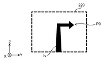
- FIG. 3C shows an example of the display content Iv visible from the display area 220.
- FIG. 3D shows an example in which the display content Iv shown in FIG. 3C is displayed so as to overlap with the actual scene shown in FIG. 3B.
- the display system 100 superimposes the display content Iv shown in FIG. 3C on the actual scene shown in FIG. 3B.
- the display reference position P0 of the display content Iv is a position determined based on the type of the display content Iv, the state (position and posture) of the vehicle 200, the map data, and the like. For example, when the display target 230 is a traveling lane and the display content Iv is an arrow indicating a traveling direction, the display reference position P0 is a display position on the liquid crystal display when the tip of the arrow points to the center of the traveling lane.
- the display reference position P0 is set, for example, in FIG. 3C at the position of the pixel on the liquid crystal display corresponding to the values of the Y coordinate and the Z coordinate in the display area 220.
- the display reference position P0 is acquired from an external device.
- the external device can be composed of, for example, a microcomputer, a CPU, an MPU, a GPU, a DSP, an FPGA, or an ASIC, and a GPS module 21.
- the function of the external device may be configured only by hardware, or may be realized by combining hardware and software.
- the display reference position P0 output from the external device may change based on the change in posture due to the number of occupants, the change in load, the decrease in gasoline, etc., so for example, when it is different from the display reference position initially acquired. There is. Therefore, the display processing device 30 may change the display reference position P0 acquired from the external device based on the change in posture due to the number of occupants, the change in load, the decrease in gasoline, and the like.
- the display processing device 30 may set the display reference position P0 based on vehicle-related information, map data, and the like.
- the display processing device 30 may set the size of the display content Iv based on the vehicle-related information.
- FIG. 4A shows an example of a state in which the vehicle 200 is in a forward leaning posture.
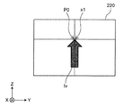
- FIG. 4B illustrates a case where the display position of the display content Iv deviates from the display target 230 according to the posture change of the vehicle 200.
- FIG. 4C shows the display position of the display content Iv after vibration correction.
- the vehicle 200 may tilt due to unevenness of the road surface, sudden acceleration or deceleration of the vehicle 200, or the like. For example, when the vehicle 200 suddenly decelerates, the vehicle 200 is in a forward leaning posture as shown in FIG. 4A. In this case, as shown in FIG. 4B, the position of the display target 230 seen from the windshield 210 changes according to the inclination of the vehicle 200. Therefore, when the display content Iv is displayed at the display reference position P0, the display content Iv deviates from the display target 230. For example, as shown in FIG. 4B, the tip of the arrow is in the oncoming lane 231.
- the display system 100 adjusts the display position of the display content Iv in the direction of returning the deviation according to the posture of the vehicle 200.
- the vibration correction processing device 50 calculates the vibration correction amount C so that the position P1 has no deviation of the display position due to the angle of the vehicle 200. That is, the display processing device 30 sets the display position of the display content Iv to "display reference position P0 + vibration correction amount C". As a result, the projection device 10 can display the display content Iv at the position P1 corresponding to the display target 230.
- the position P1 corresponding to the display target 230 in the actual scene is changed.
- the display content Iv can be displayed in.
- FIG. 5 shows an image diagram for explaining the image correction process.
- a distortion correction process when distortion occurs in the vertical direction of the display area 220 will be described.
- the sizes of the plurality of compartment areas differ due to distortion.
- the sizes of the upper regions L11 and L12 and the lower regions L15 and L16 are smaller than those in the case where there is no distortion.
- the sizes of the central regions L13 and L14 are larger than those of the compartmentalized region when there is no distortion.
- the size of the display contents Iv11 to Iv16 displayed in each section area changes, and the display positions P11 to P16 at the tips of the arrows, which are characteristic portions of the display contents Iv11 to Iv16, deviate from the superimposed positions Q11 to Q16.
- the image correction unit 34 performs image correction processing accompanied by a change in the display position of the display content Iv based on the image correction data 33g stored in advance in the storage unit 33. Specifically, the image correction unit 34 determines the image correction value using the image correction table of the image correction data 33g, and outputs the image correction value to the display control unit 32. In the example shown in FIG. 5, the image correction unit 34 determines the image correction value so that the display contents Iv11, Iv12 and Iv15, Iv16 become larger in the vertical direction in the upper regions L11, L12 and the lower regions L15, L16. ..
- the image correction unit 34 determines the image correction value so that the display contents Iv13 and Iv14 become smaller in the vertical direction in the central regions L13 and L14.
- the display control unit 32 can control the display positions P11 to P16 of the display contents Iv11 to Iv16 based on the determined image correction value and superimpose the display contents on the superimposed positions Q11 to Q16.
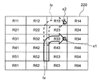
- FIG. 6A shows an example of a plurality of compartment areas R11 to R64 in the display area 220.
- the display area 220 on which the display content Iv is displayed has a plurality of partition areas R11 to R64.
- the plurality of partition areas R11 to R64 are partitioned vertically and horizontally in a mesh shape.
- the display area 220 is divided into six vertical and four horizontal division areas R11 to R64.
- the number and arrangement of the partition areas are not limited to this.
- the display area 220 may have a plurality of compartment areas.
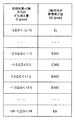
- FIG. 6B shows an example of image correction data 33 g.
- the image correction data 33g has an image correction table including image correction values U11 to U64 assigned to each of the plurality of partition areas R11 to R64 of the display area 220.
- the image correction values U11 to U64 of the image correction data 33g correspond to a plurality of division areas R11 to R64 of the display area 220, respectively.
- the image correction value U22 is adopted as the image correction value.
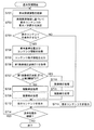
- FIG. 7 shows the display processing performed by the display control unit 32 of the display processing device 30.
- the display process shown in FIG. 7 is started, for example, when the engine of the vehicle 200 is started, or when the button for instructing the display start of the display content Iv is operated.
- the display control unit 32 acquires vehicle-related information including the position information of the vehicle 200 from the information acquisition device 20 (S101). The display control unit 32 determines whether or not to display the display content Iv corresponding to the display target 230 based on the vehicle-related information (S102).
- the display control unit 32 decides to display the display content Iv (Yes in S103)
- the display control unit 32 acquires the information indicating the display reference position P0 of the display content Iv from the external device and also acquires the content information from the storage unit 33. (S104).
- the display control unit 32 outputs the content display information to the vibration correction processing device 50 (S105).
- the content display information includes a display reference position and content information.
- the display control unit 32 acquires the image processing time Td (S106). For example, the processing switching unit 32a of the display control unit 32 calculates the image processing time Td based on the display reference position P0, the content information, and the image correction value U. It should be noted that the approximate value of the image processing time Td may be stored in advance in the content information. In this case, the display control unit 32 may use the estimated value stored in the content information as it is as the image processing time Td, or may calculate the image processing time Td based on the estimated value.
- the processing switching unit 32a switches the order of processing between the image correction processing and the vibration correction processing based on the image processing time Td. In the present embodiment, the processing switching unit 32a switches the order of processing between the image correction processing and the vibration correction processing based on the image processing time Td and the first threshold value T1.
- the processing switching unit 32a determines whether or not the image processing time Td is equal to or less than the first threshold value T1 (S107). When the image processing time Td is equal to or less than the first threshold value T1 (Yes in S107), the processing switching unit 32a switches the order of processing so that the image correction processing is performed after the vibration correction processing is performed. That is, when the image processing time Td is equal to or less than the first threshold value T1, the display processing apparatus 30 first performs vibration correction processing (S108). The display processing device 30 performs the image correction processing after performing the vibration correction processing (S109).
- the processing switching unit 32a switches the order of processing so that the vibration correction processing is performed after the image correction processing is performed. That is, when the image processing time Td is larger than the first threshold value T1, the display processing apparatus 30 performs the image correction processing (S110). The display processing device 30 performs the vibration correction processing after performing the image correction processing (S111).
- FIG. 8 shows the vibration correction processing performed by the display control unit 32 of the display processing device 30.
- the vibration correction process shown in FIG. 8 shows the details of steps S108 and S111 shown in FIG. 7.
- the display processing device 30 acquires the vibration correction amount C from the vibration correction processing device 50 (S120).
- the display control unit 32 changes the setting of the display position of the display content Iv based on the display reference position P0, the content information, and the vibration correction amount C (S121).
- the display control unit 32 reads out the image data 33i of the display content Iv corresponding to the display target from the storage unit 33 and displays it.
- the display position of the content Iv is set to "display reference position P0 + vibration correction amount C".
- the display control unit 32 reads the image data 33i of the display content Iv from the storage unit 33 and "displays" the image corrected based on the image correction value U. Set to "reference position P0 + vibration correction amount C".
- the display control unit 32 reads the image data 33i of the display content Iv from the storage unit 33, and the image is based on the image correction value U.
- the corrected image is set to "display reference position P0".
- the display control unit 32 reads the image data 33i of the display content Iv from the storage unit 33, and sets the read image into "display reference position P0 + vibration correction amount C". Set.
- the image correction process is performed based on the image correction value U at the position of the image changed in the vibration correction process.
- FIG. 9 shows an image correction process performed by the display control unit 32 of the display processing device 30.
- the image correction process shown in FIG. 9 shows the details of steps S109 and S110 shown in FIG. 7.
- the display control unit 32 acquires information indicating the image correction value U of the display content Iv from the image correction unit 34 (S130).
- the display control unit 32 changes the setting of the display position of the display content Iv based on the display reference position P0, the content information, and the image correction value U (S131). For example, the display control unit 32 corrects all the areas R11 to R64 in the display area 220 by using the image correction values U11 to U64 to enlarge, reduce, and / or rotate the image.
- the display control unit 32 sets the display position of the display content Iv to the display reference position P0 after performing the image correction.
- the display control unit 32 After performing the vibration correction process and the image correction process, the display control unit 32 displays the display content Iv (S112).
- the display control unit 32 decides not to display the display content Iv (No in S103), the display control unit 32 hides the display content Iv (S113).
- the display control unit 32 determines whether or not to continue the display process (S114). For example, when the engine of the vehicle 200 is stopped, or when the button for instructing the end of the display of the display content Iv is operated, the display control unit 32 ends the display process. To continue the display process, the process returns to step S101.
- FIG. 10 shows a calculation process of the vibration correction amount C performed by the correction control unit 52 of the vibration correction processing device 50.
- the calculation process shown in FIG. 10 is started, for example, when the engine of the vehicle 200 is started, or when the button for instructing the display start of the display content Iv is operated.
- the calculation process of FIG. 10 is started together with the display process of FIG. 7, for example.
- the calculation process shown in FIG. 10 may be started when the button for instructing the start of the position correction of the display content Iv is operated.
- the correction control unit 52 acquires the content display information of the display content Iv from the display processing device 30 (S201).
- the correction control unit 52 acquires a posture change amount indicating the angular velocity of the vehicle 200 output from the gyro sensor 41 (S202).
- the correction control unit 52 calculates the posture of the vehicle 200, that is, the deviation amount y with respect to the three axial directions, based on the posture change amount (S203).
- the correction control unit 52 calculates the vibration correction amount C based on the deviation amount y calculated based on the posture change amount (S204). For example, the correction control unit 52 determines a vibration correction amount C that restores the deviation amount y of the pitch angle.
- the correction control unit 52 outputs the information of the vibration correction amount C to the display processing device 30 (S205).
- the correction control unit 52 determines whether or not to continue the calculation process (S206). For example, when the engine of the vehicle 200 is stopped, or when the button for instructing the end of the display of the display content Iv is operated, the correction control unit 52 ends the calculation process. If the calculation process is to be continued, the process returns to step S201.
- the correction control unit 52 calculates the vibration correction amount C of the display position of the display content Iv based on the posture change amount.
- the display system 100 of the present disclosure includes a display processing device 30, an image correction unit 34, a posture detection device 40, a vibration correction processing device 50, and a processing switching unit 32a.
- the display processing device 30 controls the display of the display content Iv.
- the image correction unit 34 performs image correction processing accompanied by a change in the display position of the display content Iv based on the image correction data 33g stored in advance.
- the posture detection device 40 detects the amount of change in posture of the moving vehicle 200.
- the vibration correction processing device 50 calculates the vibration correction amount C of the display position of the display content Iv based on the posture change amount of the moving body.
- the processing switching unit 32a switches the order of processing of image correction processing that involves changing the display position of the display content Iv and vibration correction processing that corrects the display position of the display content Iv based on the vibration correction amount C.
- the display processing device 30 controls the display position of the display content Iv by performing the image correction processing and the vibration correction processing based on the order of the processing switched by the processing switching unit 32a.
- the processing switching unit 32a acquires the image processing time Td of the image correction processing.
- the processing switching unit 32a switches the order of processing between the image correction processing and the vibration correction processing based on the image processing time Td.
- the order of processing can be optimized according to the driving situation, so that the accuracy of vibration correction processing and image correction processing can be compatible and the superimposition performance and quality can be improved.
- the image processing time Td increases. For example, when there is a lot of content to be displayed (for example, when the moving object is traveling in the city area), the image processing time Td is long, and when there is little content to be displayed (for example, the moving object is traveling on the highway). Case), the image processing time Td may be shortened. Therefore, by switching the order of processing between the image correction processing and the vibration correction processing based on the image processing time Td, the optimum processing can be performed according to the traveling condition of the moving body.
- the delay time of the vibration correction processing can be shortened and the vibration correction error can be suppressed by performing the vibration correction processing after the image correction processing.
- the image processing time Td is small, the accuracy of the image correction processing can be improved by performing the image correction processing after the vibration correction processing.
- the vibration correction processing and the image correction processing can be performed in the order of the optimum processing based on the image processing time Td.
- the image processing time Td also changes. For example, when the amount of information of the display content Iv increases, the image processing time Td becomes long, and the delay time due to the vibration correction processing may become long. In this case, if the image correction process is performed after the vibration correction process is performed, the vibration correction error becomes large.
- the display system 100 since the order of processing between the vibration correction processing and the image correction processing can be switched based on the image processing time Td, the display content is displayed even when the display content Iv is updated and the amount of information changes. It is possible to suppress a decrease in the correction accuracy of the Iv display position.
- the processing switching unit 32a switches the order of processing so that the image correction processing is performed after the vibration correction processing is performed.
- the processing switching unit 32a switches the order of processing so that the vibration correction processing is performed after the image correction processing is performed.
- the present invention is not limited to this.
- the processing switching unit 32a may not be included in the display control unit 32.
- the processing switching unit 32a may switch the order of processing between the image correction processing and the vibration correction processing based on the image processing time Td of the image correction processing.
- the processing switching unit 32a may switch the order of processing between the image correction processing and the vibration correction processing based on the traveling condition of the moving body.
- the processing switching unit 32a may be the delay time from the correction to the display or the amount of increase thereof when the vibration correction processing is performed after the image correction processing. In this way, the processing switching unit 32a may switch the processing order based on information other than the image processing time Td.
- the order of the vibration correction processing and the image correction processing is switched based on the image processing time Td of the image correction processing.
- the order of the vibration correction processing and the image correction processing is switched based on whether or not a specific frequency vibration is generated.
- FIG. 11 shows a block diagram showing an internal configuration of the display system 100A according to the second embodiment.
- the display system 100A shown in FIG. 11 differs from the display system 100 of the first embodiment in that the correction control unit 52A includes a vibration detection unit 52c.
- the display system 100A shown in FIG. 11 other configurations are the same as the configuration of the display system 100 of the first embodiment.
- the vibration detection unit 52c detects whether or not the input signal contains a specific frequency band component.
- the specific frequency band component is a high frequency band component.
- the vibration detection unit 52c detects whether or not the input signal contains a high frequency band component equal to or higher than a predetermined frequency band.
- the vibration detection unit 52c includes a fluctuation amount calculation unit 52m, an offset removal filter 52e, a threshold cross detection unit 52f, a counter 52g, and a vibration determination unit 52h.
- the fluctuation amount calculation unit 52m calculates the fluctuation amount of the vehicle 200 based on the posture change amount output by the posture detection device 40. For example, the fluctuation amount calculation unit 52m calculates the angle (pitch angle) around the pitch axis of the vehicle 200 by integrating the pitch angular velocity detected by the gyro sensor 41 as the fluctuation amount. Thereby, the amount of fluctuation (pitch angle) of the vehicle 200 in the rotation direction about the Y axis (pitch axis) shown in FIG. 1 can be detected. In this embodiment, the pitch angle is calculated, but the yaw angle or the roll angle may be calculated. For example, all angles around the X-axis, Y-axis, and Z-axis may be calculated. Since both the deviation amount calculated by the deviation amount calculation unit 52a and the fluctuation amount calculated by the fluctuation amount calculation unit 52m are angle information, they may be shared or calculated as separate angle information. ..
- the offset removal filter 52e removes the offset component of the input signal (variation amount), and as a result, attenuates the low frequency band component of the input signal.
- the offset removal filter 52e is, for example, a high-pass filter.
- the relationship between the cutoff frequency Fc of the offset removal filter 52e and the frequency band lower limit F to be detected satisfies, for example, the following equation (1).
- Equation T is the total delay time (time lag) [sec] from the calculation of the correction amount of the virtual image to the display.
- the frequency setting method is not limited to the equation (1) and may be adjusted as appropriate.
- the threshold cross detection unit 52f detects that the input value straddles a predetermined threshold.
- detecting that the threshold value is crossed means, for example, detecting that the input value has changed from less than the threshold value to more than the threshold value or from more than the threshold value to less than the threshold value.
- the threshold cross detection unit 52f detects that the threshold is crossed, the threshold cross detection unit 52f outputs a detection signal to the counter 52g.
- the threshold is, for example, zero or any particular value.
- the arbitrary specific value is, for example, the value of the offset error.
- the counter 52g measures the number of times that the input value to the threshold cross detection unit 52f straddles a predetermined threshold. That is, the counter 52g counts the number of detection signals input from the threshold cross detection unit 52f to the counter 52g.
- the vibration determination unit 52h determines whether or not a specific frequency band component is generated for a certain period of time or more in the fluctuation amount based on the number of times measured by the counter 52g per unit time.
- the vibration determination unit 52h for example, provides a time window and determines the occurrence of vibration having a specific frequency band component based on the amount of change in the count value in a fixed time.
- the determination result is sent from the vibration determination unit 52h to the correction amount calculation unit 52b.
- the vibration determination unit 52h determines whether or not the high frequency band component is generated in the fluctuation amount for a certain period of time or more based on the number of times measured by the counter 52g per unit time.
- FIG. 12 shows the display processing performed by the display control unit 32 of the display processing device 30.
- Steps S301 to S305 and S308 to S314 of FIG. 12 are the same as steps S101 to S105 and S108 to S114 of FIG. 7 of the first embodiment.
- the display control unit 32 acquires vehicle-related information including the position information of the vehicle 200 from the information acquisition device 20 (S301). The display control unit 32 determines whether or not to display the display content Iv corresponding to the display target 230 based on the vehicle-related information (S302).
- the display control unit 32 decides to display the display content Iv (Yes in S303)
- the display control unit 32 acquires the information indicating the display reference position P0 of the display content Iv from the external device and also acquires the content information from the storage unit 33. (S304).
- the display control unit 32 outputs the content display information to the vibration correction processing device 50A (S305).
- the content display information includes a display reference position and content information.
- the display control unit 32 acquires the generation detection result of vibration having a high frequency band component (S306).
- the processing switching unit 32a of the display control unit 32 acquires the generation detection result of vibration having a high frequency band component from the vibration correction processing device 50A.
- the display control unit 32 acquires a signal indicating that vibration of a specific frequency is generated, which is output from the vibration correction processing device 50A.
- the display control unit 32 recognizes that vibration of a specific frequency is generated.
- the display control unit 32 does not receive the signal from the vibration correction processing device 50A, the display control unit 32 recognizes that vibration of a specific frequency has not occurred.
- the processing switching unit 32a switches the order of processing between the image correction processing and the vibration correction processing based on the detection result of vibration at a specific frequency. In the present embodiment, the processing switching unit 32a determines whether or not vibration having a high frequency band component is generated for a certain period of time or longer (S307). The processing switching unit 32a switches the order of processing between the image correction processing and the vibration correction processing based on the determination of whether or not vibration having a high frequency band component is generated for a certain period of time or longer.
- the processing switching unit 32a switches the processing order so that the image correction processing is performed after the vibration correction processing is performed. That is, when it is not detected that vibration having a high frequency band component is generated for a certain period of time or longer, the display processing apparatus 30 first performs vibration correction processing (S308). The display processing device 30 performs the image correction processing after performing the vibration correction processing (S309).
- the processing switching unit 32a switches the processing order so that the vibration correction processing is performed after the image correction processing is performed. That is, when it is detected that vibration having a high frequency band component is generated for a certain period of time or longer, the display processing apparatus 30 performs image correction processing (S310). The display processing device 30 performs the vibration correction processing after performing the image correction processing (S311).
- the vibration correction process may be the same as the vibration correction process of the first embodiment shown in FIG.
- the image correction process may be the same as the image correction process of the first embodiment shown in FIG.
- the display control unit 32 After performing the vibration correction process and the image correction process, the display control unit 32 displays the display content Iv (S312).
- the display control unit 32 decides not to display the display content Iv (No in S303), the display control unit 32 hides the display content Iv (S313).
- the display control unit 32 determines whether or not to continue the display process (S314). To continue the display process, the process returns to step S301.
- FIG. 13 shows the calculation processing of the vibration correction amount C performed by the correction control unit 52A of the vibration correction processing device 50A in the second embodiment.
- Steps S401 to S403 and S406 to S408 of FIG. 13 are the same as steps S201 to S206 of FIG. 10 of the first embodiment.
- the correction control unit 52A acquires the content display information of the display content Iv from the display processing device 30 (S401).
- the correction control unit 52A acquires a posture change amount indicating the angular velocity of the vehicle 200 output from the gyro sensor 41 (S402).
- the correction control unit 52A calculates the posture of the vehicle 200, that is, the deviation amount y with respect to the three axial directions, based on the acquired posture change amount (S403).
- the deviation amount calculation unit 52a calculates the pitch angle of the vehicle 200 by integrating the angular velocity.
- the calculated deviation amount y is sent to the correction amount calculation unit 52b.
- the fluctuation amount calculation unit 52m of the vibration detection unit 52c of the correction control unit 52A calculates the posture of the vehicle 200, for example, the fluctuation amount which is an angle with respect to the pitch direction, based on the acquired posture change amount (S404). Specifically, the fluctuation amount calculation unit 52m calculates the pitch angle of the vehicle 200 by integrating the angular velocity. The calculated fluctuation amount is sent to the offset removal filter 52e. The amount of fluctuation may be calculated after the offset is removed.
- the offset removal filter 52e of the vibration detection unit 52c removes the detected offset component of the fluctuation amount, and as a result, the low frequency band component of the fluctuation amount is also attenuated. For example, when the fluctuation amount fluctuates as shown in FIG. 14A (a), the offset removal filter 52e removes the offset component OF1 included in the fluctuation amount to obtain a 0 value as shown in FIG. 14A (b). The amount of fluctuation that vibrates with the center of the amplitude can be obtained. The amount of fluctuation in which the offset component OF1 is removed and the low frequency band component is attenuated is sent to the threshold cross detection unit 52f.
- the threshold cross detection unit 52f detects that the input fluctuation amount crosses a predetermined threshold. For example, when the fluctuation amount fluctuates as shown in FIG. 14B (a), the threshold cross detection unit 52f detects, for example, that the threshold value has changed from less than zero value to more than zero value, and FIG. 14B ( As shown in b), the detection signal is output to the counter 52g.
- the threshold cross detection unit 52f halves the detection cycle and counts the decrease change from zero value or more to less than zero value in addition to the increase change from less than zero value to zero value or more, which is the threshold value. You may.
- the counter 52g measures the number of detection signals input in a predetermined period.
- the predetermined period may be, for example, a form such as a time window, or the latest predetermined time.
- the vibration determination unit 52h determines whether or not vibration having a high frequency band component is generated in the fluctuation amount (S405).
- the vibration determination unit 52h determines, for example, whether or not the fluctuation amount includes a high frequency band component by comparing the number of times the fluctuation amount crosses the threshold value with the count threshold value within a predetermined period.
- the vibration determination unit 52h compares the number of times the counter 52g has counted with the count threshold value.
- the vibration determination unit 52h determines that the number of times the counter 52g has counted is smaller than the count threshold, it determines that the fluctuation amount does not include the high frequency band component for a certain period of time or longer, and the vibration of the vehicle 200 has a high frequency based on this determination result. Recognize that vibration with band components is not included.
- the vibration determination unit 52h determines that the number of times the counter 52g has counted is equal to or greater than the count threshold value, the vibration determination unit 52h recognizes that the fluctuation amount includes vibration having a high frequency band component.
- the correction control unit 52A outputs the generation detection result of vibration having a high frequency band component to the display processing device 30 (S405). Specifically, when vibration having a high frequency band component is generated, a signal indicating that vibration having a high frequency band component is generated is sent to the display processing device 30.
- the correction control unit 52A calculates the vibration correction amount C based on the deviation amount y calculated based on the posture change amount (S407). For example, the correction control unit 52A determines a vibration correction amount C that restores the deviation amount y of the pitch angle.
- the correction control unit 52A outputs the information of the vibration correction amount C to the display processing device 30 (S408).
- the correction control unit 52A determines whether or not to continue the calculation process (S409). For example, when the engine of the vehicle 200 is stopped, or when the button for instructing the end of the display of the display content Iv is operated, the correction control unit 52A ends the calculation process. To continue the calculation process, the process returns to step S401.
- the display system 100A of the present embodiment includes a vibration detection unit 52c that detects that vibration having a specific frequency band component is generated for a certain period of time or longer in the posture change of the moving body.
- the process switching unit 32a switches the order of processing between the image correction process and the vibration correction process based on the detection result of the vibration detection unit 52c.
- Vibration having a specific frequency band component is high frequency vibration having a high frequency band component.
- the processing switching unit 32a switches the order of processing so that the vibration correction processing is performed after the image correction processing is performed when the vibration having the high frequency band component is generated for a certain period of time or longer. Further, the processing switching unit 32a switches the order of processing so that the image correction processing is performed after the vibration correction processing is performed when the vibration having the high frequency band component is not generated for a certain period of time or more.
- the allowable delay time of vibration correction processing for the target superimposition accuracy differs depending on the vibration frequency.
- the delay time of the vibration correction process means the time from the calculation of the vibration correction amount to the display. For example, the higher the vibration frequency, the shorter the allowable delay time of the vibration correction process in order to suppress the vibration correction error to a certain level or less. Therefore, it is detected that vibration having a high frequency band component higher than a specific frequency band is generated in the posture fluctuation of the moving body for a certain period of time or longer, and the image correction process and the vibration correction process are performed according to the detection result.
- the optimum processing can be performed according to the traveling condition of the moving body. For example, when vibration having a high frequency band component is generated for a certain period of time or longer, the delay time of the vibration correction process is shortened and the band on the high frequency side that can be corrected is expanded by performing the vibration correction process after the image correction process. It is possible to suppress the vibration correction error. When vibration having a high frequency band component has not occurred for a certain period of time or more, the accuracy of the image correction processing can be improved by performing the image correction processing after the vibration correction processing.
- vibration is performed in the order of optimum processing based on the detection result of vibration having a high frequency band component. Correction processing and image correction processing can be performed.
- the frequency band and amplitude of the vibration generated by the track conditions vary variously, for example, when applying a filter process such as a high-pass filter, a low-pass filter, or a band-pass filter, the amplitude of the vibration must be used as a criterion. It must be, but it is difficult to predict the amplitude of the vibration. It is difficult to set the optimum threshold value for filtering.
- the high frequency component is detected by the counter value, it is not necessary to include the vibration amplitude in the determination standard, and the high frequency band can be detected with high accuracy.
- the vibration detection unit 52c includes a fluctuation amount calculation unit 52m, an offset removal filter 52e, a threshold cross detection unit 52f, a counter 52g, and a vibration determination unit 52h has been described. Not limited to.
- the vibration detection unit 52c may detect that vibration having a specific frequency band component is generated for a certain period of time or longer.
- the vibration correction amount C may be set to "0".
- the specific frequency vibration is a vibration having a high frequency band component
- the specific frequency vibration may be a vibration having a low frequency band component below a predetermined frequency band.
- the processing switching unit 32a may switch the order of the vibration correction processing and the image correction processing based on whether or not the vibration having the low frequency band component is generated for a certain period of time or longer. Specifically, when the vibration having a low frequency band component is generated for a certain period of time or longer, the processing switching unit 32a may perform the image correction processing after performing the vibration correction processing. When the processing switching unit 32a does not generate vibration having a low frequency band component for a certain period of time or longer, the processing switching unit 32a may perform the vibration correction processing after performing the image correction processing.
- the vibration correction amount C is calculated based on the deviation amount regardless of the order of processing.
- the vibration correction amount C is calculated based on the deviation amount, and when the vibration correction processing is performed after the image correction processing, the deviation amount and the image correction error are set. Based on this, the vibration correction amount C is calculated. Further, in the present embodiment, the calculation process of the vibration correction amount C is switched based on the image processing time Td.
- FIG. 15 shows a block diagram showing an internal configuration of the display system 100B according to the third embodiment.
- the display system 100B shown in FIG. 15 is different from the display system 100 of the first embodiment in that the correction control unit 52B includes an image correction error calculation unit 52d.
- the display system 100B shown in FIG. 15 other configurations are the same as the configuration of the display system 100 of the first embodiment.
- the image correction error calculation unit 52d calculates the image correction error of the image correction process caused by the vibration correction process for correcting the display deviation caused by the posture change of the vehicle 200. Specifically, the image correction error calculation unit 52d calculates the initial position of the display content Iv based on the content display information output from the display processing device 30.
- the initial position means the display position of the display content Iv when the vibration correction amount is “0”.
- the initial position may be a display reference position first acquired from an external device, or may be a position of a feature portion of the display content Iv when the vibration correction amount is “0”.
- the initial position is the display position of the characteristic portion of the display content Iv when the vibration correction amount is "0".
- the feature portion is the tip portion of the arrow.
- the initial position is the display position of the tip of the arrow.
- FIG. 16A is a diagram showing an example of the initial position x1 of the display content Iv.
- the display content Iv shown in FIG. 16A is an arrow having a linear shape extending in one direction.
- the initial position x1 of the display content Iv coincides with the display reference position P0 which is the display position of the display content Iv when the vibration correction amount is “0”.
- FIG. 16B is a diagram showing another example of the initial position x1 of the display content Iv.
- the display content Iv shown in FIG. 16B is an arrow having a shape bent by 90 °.
- the initial position x1 of the display content Iv is different from the display reference position P0.
- the image correction error calculation unit 52d acquires an image correction value (image correction data) from the display processing device 30 via the communication unit 31.
- the image correction error calculation unit 52d is an image based on the initial position of the display content Iv, the deviation amount calculated by the deviation amount calculation unit 52a, and the image correction value (image correction data) acquired from the display processing device 30. Calculate the correction error.
- the image correction error calculation unit 52d acquires a correction value (first image correction value) for image correction at the initial position of the display content Iv. Further, the image correction error calculation unit 52d acquires a correction value (second image correction value) for image correction at the display position of the display content Iv that has been vibration-corrected based on the deviation amount calculated by the deviation amount calculation unit 52a. do.
- the image correction error calculation unit 52d calculates the image correction error by subtracting the first image correction value from the second image correction value. That is, the image correction error is the display of the display content Iv displayed when the first image correction value at the initial position of the display content Iv and the vibration correction based on the deviation amount calculated by the deviation amount calculation unit 52a are performed. It is the difference from the second image correction value at the position.
- the image correction error calculation unit 52d stores a correction value table to which correction values for image correction corresponding to the amount of deviation from the initial position are assigned.
- the image correction error calculation unit 52d has a storage unit and stores the correction value table in the storage unit.
- the image correction error calculation unit 52d calculates the image correction error based on the initial position, the deviation amount, and the correction value table.
- the correction value of the image correction corresponding to the deviation amount from the initial position may be referred to as a first correction value
- the correction value table may be referred to as a first correction value table
- the correction amount calculation unit 52b calculates the vibration correction amount C based on the deviation amount y.
- the correction amount calculation unit 52b calculates the vibration correction amount C based on the deviation amount y when the image processing time Td is equal to or less than the first threshold value T1.
- the correction amount calculation unit 52b When the vibration correction process is performed after the image correction process, the correction amount calculation unit 52b has an image correction error of the image correction process caused by the vibration correction process for correcting the deviation amount y and the display deviation caused by the posture change of the vehicle 200. And, the vibration correction amount C is calculated based on.
- the correction amount calculation unit 52b calculates the vibration correction amount C based on the deviation amount y and the image correction error. Specifically, the correction amount calculation unit 52b calculates the vibration correction amount C based on the deviation amount y calculated by the deviation amount calculation unit 52a and the image correction error calculated by the image correction error calculation unit 52d. do.
- FIG. 17 shows an example in which an image correction error E1 of the image correction processing occurs when the vibration correction processing is performed after the image correction processing is performed.
- the display area 220 is distorted in the vertical direction. Therefore, when the display area 220 is divided into a plurality of compartment areas, the sizes of the plurality of compartment areas differ due to distortion.
- the sizes of the upper areas L21 and L22 and the lower areas L25 and L26 are smaller than those of the section area when there is no distortion. Further, the sizes of the central regions L23 and L24 are larger than those of the compartmentalized region when there is no distortion. Therefore, in the upper regions L21 and L22 and the lower regions L25 and L26, the display content Iv is corrected so as to increase in the vertical direction. Further, in the central regions L23 and L24, the display content Iv is corrected so as to be smaller in the vertical direction.
- the reduction process is applied and the display content Iv is corrected so as to be smaller in the vertical direction.
- the enlargement processing is applied, and the display content Iv is corrected so as to increase in the vertical direction.
- the display position of the display content Iv is not changed by the vibration correction process. Therefore, the display position of the display content Iv21 after the vibration correction is not changed from the display reference position P0. That is, the display content Iv21 does not deviate from the superimposed position.
- the display content Iv is an arrow having a shape bent by 90 °
- the initial position x1 is the same as the display reference position P0 in the yaw axis direction (Z axis direction), but the present invention is limited to this. Not done.
- the initial position x1 may be different from the display reference position P0.
- the target display position P2 of the corrected display content Iv22 is calculated by "display reference position (initial position) P0 + vibration correction amount C10".
- the target display position P2 is calculated by "initial position x1 + vibration correction amount C10". ..
- the display content Iv22 is displayed in the upper region L22 one above the central region L23 (see “A3” in FIG. 17).
- the display content Iv22 is displayed in the upper region L22
- the enlargement processing of “A4 ⁇ A3” of the upper region L22 in FIG. 17 is applied as the image correction processing. That is, when the display content Iv22 is displayed in the upper region L22, it is preferable that the display content Iv is corrected so as to increase in the vertical direction.
- the vibration correction process is performed after the image correction process is performed.
- the display content Iv is displayed in the central region L23 before the vibration correction process is performed, that is, when the image correction process is performed. Therefore, in the image correction processing, the reduction processing of “A1 ⁇ A2” of the central region L23 of FIG. 17 is applied instead of the enlargement processing of “A4 ⁇ A3” of the upper region L22 of FIG. That is, the display content Iv is corrected so as to be smaller in the vertical direction.
- the vibration correction amount C of the display position of the display content Iv is calculated based on the vibration and the image correction error. As a result, it is possible to prevent the display position of the corrected display content Iv from deviating from the target display position, and to suppress a decrease in the correction accuracy of the display position of the display content Iv.
- FIG. 18 shows the correction processing performed by the correction control unit 52B of the vibration correction processing device 50B.
- Steps S501 to S503, S506, and S509 to S510 in FIG. 18 are the same as steps S201 to S206 in FIG. 10 of the first embodiment.
- the correction control unit 52B acquires the content display information of the display content Iv from the display processing device 30 (S501).
- the correction control unit 52B acquires a posture change amount indicating the angular velocity of the vehicle 200 output from the gyro sensor 41 (S502).
- the correction control unit 52B calculates the posture of the vehicle 200, that is, the deviation amount y with respect to the three axial directions, based on the posture change amount (S503).
- the correction control unit 52B changes the calculation process of the vibration correction amount C based on the order of the image correction process and the vibration correction process. Specifically, when the image correction process is performed after the vibration correction process, the correction control unit 52B calculates the vibration correction amount based on the deviation amount y. When the vibration correction process is performed after the image correction process, the correction control unit 52B calculates the vibration correction amount C based on the deviation amount y and the image correction error E1. In the present embodiment, the correction control unit 52B switches the calculation process of the vibration correction amount C based on the image processing time Td of the image correction process and the first threshold value T1.
- the correction control unit 52B acquires information on the image processing time Td (S504).
- the correction control unit 52B acquires information on the image processing time Td from the display processing device 30.
- the correction control unit 52B determines whether or not the image processing time Td is equal to or less than the first threshold value T1 (S505). When the image processing time Td is equal to or less than the first threshold value T1 (Yes in S505), the correction control unit 52B calculates the vibration correction amount C based on the deviation amount y (S506).
- the correction control unit 52B calculates the vibration correction amount C based on the deviation amount y and the image correction error E1. Specifically, the correction control unit 52B determines the posture change of the vehicle 200 based on the content display information, the deviation amount y calculated based on the posture change amount, and the image correction value U (image correction data). The image correction error E1 of the image correction caused by the vibration correction process for correcting the display deviation caused by the accompanying calculation is calculated (S507). The correction control unit 52B calculates an initial position x1 which is a display position of the display content Iv when the vibration correction amount is "0" based on the content display information output from the display processing device 30.
- the initial position x1 may change depending on the display reference position P0 and / or the feature portion of the display content Iv (see FIGS. 16A and 16B). Therefore, the initial position x1 is calculated based on the content display information (for example, display reference position P0, content information).
- the correction control unit 52B calculates the image correction error E1 based on the initial position x1 of the display content Iv, the deviation amount y, and the image correction value U (image correction data).
- the image correction error E1 is calculated by the difference between the first image correction value at the initial position x1 of the display content Iv and the second image correction value at the display position of the display content Iv after vibration correction based on the deviation amount y. Will be done.
- the calculation of the image correction error E1 will be described.
- the image correction error E1 can be calculated in all the partition areas shown in FIGS. 6A and 6B, while the vibration correction amount C is one. Therefore, the image correction error E1 that can be added to the vibration correction is also one. Since the display content Iv is displayed across a plurality of compartment areas, the image correction error of which of the plurality of compartment areas in which the display content Iv is located is selected to be added to the vibration correction amount. , The correction accuracy of the display content Iv can be improved. In the present embodiment, the display position of the feature portion of the display content Iv, that is, the partition area used for calculating the image correction error E1 based on the initial position x1 is selected. This makes it possible to improve the accuracy of the display deviation correction of the characteristic portion of the display content Iv.
- FIG. 19A shows an example of the display position of the display content Iv before and after the vibration correction in the display area 220.
- FIG. 19B is a diagram illustrating a first image correction value before vibration correction and a second image correction value after vibration correction in the example of FIG. 19A.
- the display content Iv represented by the solid line indicates the display position before the vibration correction
- the display content Iv represented by the dotted line indicates the display position after the vibration correction.
- FIG. 19B shows an image correction table including image correction values U11 to U64 assigned to each of the plurality of partition areas R11 to R64 of the display area 220 shown in FIG. 19A.
- the tip of the arrow which is a characteristic portion of the display content Iv
- the initial position x1 of the display content Iv is the first section area R33.
- the tip of the arrow which is a characteristic portion of the display content Iv
- the display position x2 of the characteristic portion of the display content Iv after the vibration correction is the second section region R13.
- the first image correction value assigned to the first section area R33 is “U33”.
- the second image correction value assigned to the second section area R13 is "U13".
- the image correction error E1 is calculated by subtracting the first image correction value U33 from the second image correction value U13.
- the correction control unit 52B has a first correction value table to which the first correction value Ea of the image correction corresponding to the deviation amount y from the initial position x1 is assigned.
- the correction control unit 52B calculates the image correction error E1 based on the initial position x1, the deviation amount y, and the first correction value table.
- the correction control unit 52B acquires the correction value Ex as the first image correction value for image correction at the initial position x1.
- the correction value Ex is acquired from the image correction values U11 to U64 assigned to the plurality of partition areas R11 to R64 shown in FIGS. 6A and 6B.
- the correction control unit 52B refers to the first correction value table and uses the first correction value as the second image correction value of the image correction at the display position x2 of the display content Iv after the vibration correction based on the deviation amount y from the initial position x1. Acquire the correction value Ea.
- the correction control unit 52B calculates the image correction error E1 by subtracting the correction value Ex from the first correction value Ea.
- FIG. 20 shows an example of a first correction value table including the first correction value Ea of the image correction assigned to the deviation amount y from the initial position x1 of the display content Iv.
- a first correction value table including a first correction value Ea showing an image correction value in the Z-axis direction corresponding to an angle deviation amount y around the Y-axis from the initial position x1 is shown.
- the first correction value Ea is set every time the angle deviation amount y changes by 0.01 [deg.].
- the first correction value Ea is E100, and the angle deviation amount y is ⁇ M / 100 ⁇ y ⁇ (M-1) / 100. At that time, the first correction value Ea is Em. Further, when the angle deviation amount y is 0.00 ⁇ y ⁇ +0.01, the first correction value Ea is E200, and when the angle deviation amount y is + (N-1) / 100 ⁇ y ⁇ + N / 100, The first correction value Ea is En. Note that "M" and "N" mean arbitrary constants.
- the present invention is not limited to this.
- the range of the deviation amount y to which the first correction value Ea is assigned is not limited to every 0.01 [deg.].
- the first correction value Ea is assigned to the deviation amount y in the pitch axis direction from the initial position x1, but the deviation amount in the yaw axis direction and the roll direction from the initial position x1.
- a correction value may be assigned to.
- the correction value Ex (first image correction value) for image correction at the initial position x1 of the display content Iv is calculated based on the initial position x1 and the image correction data 33g. For example, when the initial position x1 is in the compartment area R23 shown in FIG. 6A, the correction value Ex is determined to be the image correction value U23.
- the first correction value Ea (second image correction value) for image correction at the display position x2 of the display content Iv after vibration correction based on the deviation amount y from the initial position x1 is the initial position x1, the deviation amount y, and the first. Calculated based on the correction value table.
- the display position x2 of the display content Iv after vibration correction is a position of ⁇ 0.015 [deg.] Around the Y axis from the initial position x1, the deviation is referred to with reference to the first correction value table shown in FIG.
- the image correction value E101 in the Z direction corresponding to the amount “ ⁇ 0.02 ⁇ y ⁇ 0.01” is determined as the first correction value Ea.
- the image correction error E1 is calculated by subtracting the image correction value U23 from the image correction value E101.
- the correction control unit 52B calculates the initial position x1 which is the display position of the characteristic portion of the display content Iv when the vibration correction amount is "0" based on the content display information. For example, when the display content Iv is an arrow, the correction control unit 52B calculates the display position of the tip of the arrow when the vibration correction amount is “0” as the initial position ⁇ 1.
- the first correction value Ea is the first image correction value (correction value Ex) of the first display position (initial position) of the feature portion of the display content Iv when the vibration correction amount is "0", and the display after vibration correction. It is calculated based on the difference between the second image correction value (first correction value Ea) of the second display position of the feature portion of the content Iv. Thereby, the display processing device 30 can control the display position of the feature portion of the display content Iv.
- the correction control unit 52B calculates the vibration correction amount C based on the deviation amount y and the image correction error E1 (S508). For example, the correction control unit 52B restores the deviation amount y of the pitch angle and determines the vibration correction amount C so as to eliminate the image correction error E1. Specifically, the correction control unit 52B calculates the deviation correction amount by converting the deviation amount y, which is the angle information, into the number of pixels. The correction control unit 52B adds the image correction error E1 to the deviation correction amount, and determines the vibration correction amount C that restores the number of pixels corresponding to the deviation.
- the correction control unit 52B outputs the information of the vibration correction amount C to the display processing device 30 (S509).
- the correction control unit 52B determines whether or not to continue the calculation process (S510). If the calculation process is to be continued, the process returns to step S501.
- the vibration correction processing device 50B when the processing switching unit 32a switches the processing order so that the vibration correction processing is performed after the image correction processing is performed, the vibration correction processing device 50B has the deviation amount y and the image correction.
- the vibration correction amount C is calculated based on the error E1.
- the vibration correction processing device 50B calculates the deviation amount y of the display position of the display content Iv based on the posture change amount of the moving body.
- the vibration correction processing device 50B calculates the initial position x1 of the display content Iv based on the content display information output from the display processing device 30.
- the vibration correction processing device 50B calculates the image correction error E1 based on the initial position x1, the deviation amount y, and the image correction value U (image correction data).
- the vibration correction processing device 50B calculates the vibration correction amount C based on the deviation amount y and the image correction error E1.
- the vibration correction processing device 50B has a first correction value table to which the first correction value Ea of the image correction processing corresponding to the deviation amount y from the initial position x1 is assigned, and has the initial position x1, the deviation amount y, and the first.
- the image correction error E1 is calculated based on the correction value table.
- the image correction error E1 can be easily calculated based on the deviation amount y from the initial position x1. As a result, the positional deviation of the display position of the display content Iv can be further suppressed.
- the vibration correction processing device 50B may acquire a processing switching signal from the processing switching unit 32a of the display processing device 30 and switch the calculation process of the vibration correction amount C based on the processing switching signal.
- the display processing device 30 switches the signal for switching to the calculation processing of the vibration correction amount C based on the deviation amount y and the image correction error E1 when the image processing time Td is larger than the first threshold value T1. It may be output to 50B.
- the display processing device 30 outputs a signal for switching to the calculation processing of the vibration correction amount C based on the deviation amount y to the vibration correction processing device 50B when the image processing time Td is equal to or less than the first threshold value T1. good.
- the correction control unit 52B has a first correction value table showing the first correction value Ea of the image correction corresponding to the deviation amount y from the initial position of the display content Iv has been described, but the present invention is limited to this. Not done.
- the correction control unit 52B does not have to have the first correction value table.
- the storage unit 53 may store the first correction value table.
- the correction control unit 52B may read out the first correction value table stored in the storage unit 53 and calculate the image correction error E1.
- the image correction error E1 is calculated using the first correction value table to which the first correction value Ea of the image correction corresponding to the deviation amount y of the angle from the initial position x1 of the display content Iv is assigned.
- the image correction error E1 may be calculated using the second correction value table to which the second correction value of the image correction corresponding to the deviation correction amount of the number of pixels from the initial position of the display content Iv is assigned.
- FIG. 21 shows a flowchart showing a calculation process of the vibration correction amount C of the modified example in the third embodiment.
- the calculation process of the vibration correction amount C in the modification shown in FIG. 21 includes steps S520 to S522 instead of steps S507 to S508 of the third embodiment shown in FIG. Steps S520 to S522 show the calculation process of the vibration correction amount C when the vibration correction process is performed after the image correction process.
- steps S520 to S522 in FIG. 21 will be described.
- the correction control unit 52B calculates the deviation correction amount G based on the deviation amount y calculated based on the posture change amount (S520).
- the correction control unit 52B converts the deviation amount y into the number of pixels and determines the deviation correction amount G that cancels the deviation amount indicated by the number of pixels.
- the correction control unit 52B calculates the image correction error E1 based on the content display information and the deviation correction amount G (S521).
- the correction control unit 52B has a second correction value table to which the second correction value Eb of the image correction corresponding to the deviation correction amount G from the initial position x1 of the display content Iv is assigned.
- the second correction value table is stored in a storage unit provided in the image correction error calculation unit 52d.
- FIG. 22 shows an example of a second correction value table including the second correction value Eb of the image correction assigned to the deviation correction amount G from the initial position x1 of the display content Iv.
- a second correction value table including a second correction value Eb showing an image correction value in the Z-axis direction corresponding to the deviation correction amount G in the Z direction from the initial position x1 is shown.
- the second correction value Eb is set for every 1 [pixel] of the deviation correction amount G.
- the second correction value Eb is E300
- the second correction value Eb is Eb
- the correction value Eb is Ej.
- the second correction value Eb becomes E400
- the deviation correction amount G is + (K-1) ⁇ G ⁇ + K
- the second correction value is obtained.
- Eb becomes Ek. Note that "J" and "K” mean arbitrary constants.
- a second correction value Eb is assigned every time the deviation correction amount G from the initial position x1 changes by 1 [pixel], but the present invention is not limited to this.
- the range of the deviation correction amount G to which the second correction value Eb is assigned is not limited to 1 [pixel].
- the second correction value Eb is assigned to the deviation correction amount G in the pitch axis direction, but the second correction value is assigned to the deviation correction amount in the yaw axis direction and the roll direction. It may be assigned.
- the correction control unit 52B calculates the image correction error E1 based on the initial position x1 of the display content Iv, the deviation correction amount G, and the second correction value table. Specifically, the correction control unit 52B acquires a correction value Ex (first image correction value) for image correction at the initial position x1. Further, the correction control unit 52B refers to the second correction value table, and the second correction value Eb (second correction value Eb) of the image correction at the display position of the display content Iv after the vibration correction based on the deviation correction amount G from the initial position x1. Image correction value) is acquired. The correction control unit 52B calculates the image correction error E1 by subtracting the correction value Ex from the second correction value Eb.
- the image correction error E1 is the correction value Ex (first image correction value) at the initial position x1 of the display content Iv and the display position x2 of the display content Iv after vibration correction based on the deviation correction amount G from the initial position x1. It is calculated by the difference between the second correction value Eb (second image correction value) and.
- the correction value Ex for image correction at the initial position x1 of the display content Iv is calculated based on the initial position x1 and the image correction data 33g. For example, when the initial position x1 is in the compartment area R23 shown in FIG. 6A, the correction value Ex is determined to be the image correction value U23 shown in FIG. 6B.
- the second correction value Eb of the image correction at the display position of the display content Iv after the vibration correction based on the deviation correction amount G is calculated based on the initial position x1, the deviation correction amount G, and the second correction value table. For example, when the display position of the display content Iv after vibration correction based on the deviation correction amount G is a position of ⁇ 0.8 [pixel] in the Z-axis direction from the initial position x1, the second correction value table shown in FIG. 22 is displayed. With reference to this, the image correction value E300 in the Z direction corresponding to the deviation correction amount “ ⁇ 1.0 ⁇ G ⁇ 0.0” is determined as the second correction value Eb. In this case, the image correction error E1 is calculated by subtracting the image correction value U23 from the image correction value E300.
- the correction control unit 52B calculates the vibration correction amount C based on the deviation correction amount G and the image correction error E1 (S522).
- the correction control unit 52B calculates the vibration correction amount C by adding the image correction error E1 to the deviation correction amount G. Specifically, the correction control unit 52B adds the image correction error E1 to the deviation correction amount G, and determines the vibration correction amount C that restores the number of pixels corresponding to the deviation. For example, the correction control unit 52B restores the pitch angle deviation correction amount G and determines a vibration correction amount C that eliminates the image correction error E1.
- the calculation process of the vibration correction amount C is switched based on the image processing time Td. In the present embodiment, the calculation process of the vibration correction amount C is switched based on whether or not the specific frequency vibration is generated.
- FIG. 23 shows a block diagram showing an internal configuration of the display system 100C according to the fourth embodiment.
- the display system 100C shown in FIG. 23 has the same configuration as the display system 100A of the second embodiment except that the correction control unit 52C includes an image correction error calculation unit 52d. Further, the image correction error calculation unit 52d of the fourth embodiment is the same as that of the third embodiment.
- the correction amount calculation unit 52b calculates the vibration correction amount C based on the deviation amount y.
- the specific frequency vibration is a vibration having a high frequency band component.
- the correction amount calculation unit 52b calculates the vibration correction amount C based on the deviation amount y when the vibration having the high frequency band component has not occurred for a certain period of time or more.
- the correction amount calculation unit 52b When the vibration correction process is performed after the image correction process, the correction amount calculation unit 52b has an image correction error of the image correction process caused by the vibration correction process for correcting the deviation amount y and the display deviation caused by the posture change of the vehicle 200. And, the vibration correction amount C is calculated based on. In the present embodiment, the correction amount calculation unit 52b calculates the vibration correction amount C based on the deviation amount y and the image correction error when the vibration having the high frequency band component is generated for a certain period of time or longer. Specifically, the correction amount calculation unit 52b calculates the vibration correction amount C based on the deviation amount y calculated by the deviation amount calculation unit 52a and the image correction error calculated by the image correction error calculation unit 52d. do.
- FIG. 24 shows the correction processing performed by the correction control unit 52C of the vibration correction processing device 50C.
- Steps S601 to S603 and S607 to S611 in FIG. 24 are the same as steps S501 to S503 and S506 to S510 in FIG. 18 of the third embodiment. Further, steps S604 and S605 of FIG. 24 are the same as steps S404 and S405 of FIG. 13 of the second embodiment.
- the correction control unit 52C acquires the content display information of the display content Iv from the display processing device 30 (S601).
- the correction control unit 52C acquires a posture change amount indicating the angular velocity of the vehicle 200 output from the gyro sensor 41 (S602).
- the correction control unit 52C calculates the posture of the vehicle 200, that is, the deviation amount y with respect to the three axial directions, based on the posture change amount (S603).
- the correction control unit 52C detects whether or not vibration having a high frequency band component is generated for a certain period of time or longer in the deviation amount y (S604).
- the correction control unit 52C outputs the detection result of the vibration having the high frequency band component to the display processing device 30 (S605).
- the correction control unit 52C switches the calculation process of the vibration correction amount C based on the detection result of the vibration having the high frequency band component. Specifically, the correction control unit 52C determines whether or not vibration having a high frequency band component is generated (S606). When vibration having a high frequency band component is not generated (No in S606), the correction control unit 52C calculates the vibration correction amount C based on the deviation amount y (S607).
- the correction control unit 52C calculates the vibration correction amount C based on the deviation amount y and the image correction error E1. Specifically, the correction control unit 52C calculates the image correction error E1 based on the content display information, the deviation amount y, and the image correction value U (image correction data) (S608). After calculating the image correction error E1, the correction control unit 52C calculates the vibration correction amount C based on the deviation amount y and the image correction error E1 (S609).
- the correction control unit 52C outputs the information of the vibration correction amount C to the display processing device 30 (S610).
- the correction control unit 52C determines whether or not to continue the calculation process (S611). If the calculation process is to be continued, the process returns to step S601.
- the vibration correction processing device 50B when the processing switching unit 32a switches the processing order so that the vibration correction processing is performed after the image correction processing is performed, the vibration correction processing device 50B has the deviation amount y and the image correction.
- the vibration correction amount C is calculated based on the error E1.
- the vibration correction processing device 50B calculates the deviation amount y of the display position of the display content Iv based on the posture change amount of the moving body.
- the vibration correction processing device 50B calculates the initial position x1 of the display content Iv based on the content display information output from the display processing device 30.
- the vibration correction processing device 50B calculates the image correction error E1 based on the initial position x1, the deviation amount y, and the image correction value U (image correction data).
- the vibration correction processing device 50B calculates the vibration correction amount C based on the deviation amount y and the image correction error E1.
- the vibration correction processing device 50B determines the deviation amount y and the image correction error E1.
- An example of calculating the vibration correction amount C based on the above has been described, but the present invention is not limited to this.
- the vibration correction processing device 50B may calculate the vibration correction amount C based on the deviation correction amount G based on the deviation amount y and the image correction error E1.
- FIG. 25 shows a flowchart showing a calculation process of the vibration correction amount C of the modified example in the fourth embodiment.
- the calculation process of the vibration correction amount C in the modification shown in FIG. 25 includes steps S620 to S622 instead of steps S608 to S609 of the fourth embodiment shown in FIG. 22.
- Steps S620 to S622 show the calculation process of the vibration correction amount C when the vibration correction process is performed after the image correction process. Since steps S620 to S622 are the same as steps S520 to S522 of the modified example of the third embodiment shown in FIG. 21, the description thereof will be omitted.
- the specific frequency vibration is a vibration having a high frequency band component
- the specific frequency vibration may be a vibration having a low frequency band component below a predetermined frequency band.
- the processing switching unit 32a may switch the order of the vibration correction processing and the image correction processing based on whether or not the vibration having the low frequency band component is generated for a certain period of time or longer. Specifically, when the vibration having a low frequency band component is generated for a certain period of time or longer, the processing switching unit 32a may perform the image correction processing after performing the vibration correction processing. When the processing switching unit 32a does not generate vibration having a low frequency band component for a certain period of time or longer, the processing switching unit 32a may perform the vibration correction processing after performing the image correction processing.
- the order of the correction processing and the calculation processing of the vibration correction amount C are switched based on the detection result of the vibration having the image processing time Td or the high frequency band component equal to or higher than the specific frequency band.
- the order of correction processing and the calculation processing of the vibration correction amount C are switched based on the first image correction error assigned to each of the plurality of division areas of the display area.
- the internal configuration of the display system of the fifth embodiment is the same as the internal configuration of the display system 100B of the third embodiment shown in FIG. Therefore, in the fifth embodiment, the same reference numerals as those in the third embodiment will be used for description.
- FIG. 26 shows the display processing performed by the display control unit 32 of the display processing device 30 according to the fifth embodiment.
- Steps S701 to S705 and S708 to S714 of FIG. 26 are the same as steps S101 to S105 and S108 to S114 of FIG. 7 of the first embodiment.
- the display control unit 32 acquires vehicle-related information including the position information of the vehicle 200 from the information acquisition device 20 (S701). The display control unit 32 determines whether or not to display the display content Iv corresponding to the display target 230 based on the vehicle-related information (S702).
- the display control unit 32 decides to display the display content Iv (Yes in S703), the display control unit 32 acquires the information indicating the display reference position P0 of the display content Iv from the external device and also acquires the content information from the storage unit 33. (S704). The display control unit 32 outputs the content display information to the vibration correction processing device 50B (S705).
- the display control unit 32 acquires the first image correction error E11 (S706).
- the first image correction error E11 is an image correction error caused by a change in the display position by the vibration correction process after the image correction accompanied by the change in the display position of the display content Iv.
- the first image correction error E11 is an error in consideration of the image correction error of all the section areas R11 to R64 in the display area 220 of the display content Iv.
- the calculation of the first image correction error E11 is calculated by the same method as the calculation of the image correction error E1 described in the third embodiment.
- the first image correction error E11 is calculated based on the initial position x1 of the display content Iv and the deviation amount y using the first correction value table shown in FIG.
- the first image correction error E11 is calculated based on the initial position x1 of the display content Iv and the deviation correction amount G using the second correction value table shown in FIG.
- the first image correction error E11 is calculated by the vibration correction processing device 50B and output to the display processing device 30.
- the display processing device 30 acquires the first image correction error E11 from the vibration correction processing device 50B.
- the process switching unit 32a of the display control unit 32 switches the order of processing between the image correction process and the vibration correction process based on the first image correction error E11.
- the processing switching unit 32a determines whether or not the absolute value of the first image correction error E11 is equal to or greater than the second threshold value T2 (S707).
- the display control unit 32 switches the order of processing so that the image correction processing is performed after the vibration correction processing is performed. .. That is, when the absolute value of the first image correction error E11 is equal to or greater than the second threshold value T2, the display processing device 30 first performs vibration correction processing (S708).
- the display processing device 30 performs the image correction processing after performing the vibration correction processing (S709).
- the processing switching unit 32a switches the order of processing so that the vibration correction processing is performed after the image correction processing is performed. That is, when the absolute value of the first image correction error E11 is smaller than the second threshold value T2, the display processing device 30 performs the image correction processing (S710). The display processing device 30 performs the vibration correction processing after performing the image correction processing (S711).
- the display control unit 32 After performing the vibration correction process and the image correction process, the display control unit 32 displays the display content Iv (S712).
- the display control unit 32 decides not to display the display content Iv (No in S703), the display control unit 32 hides the display content Iv (S713).
- the display control unit 32 determines whether or not to continue the display process (S714). If the display process is to be continued, the process returns to step S701.
- FIG. 27 shows the calculation processing of the vibration correction amount C performed by the correction control unit 52B of the vibration correction processing device 50B according to the fifth embodiment.
- Steps S801 to S803 and S807 to S811 of FIG. 27 are the same as steps S501 to S503 and S506 to 510 of FIG. 18 of the third embodiment.
- the correction control unit 52B acquires the content display information of the display content Iv from the display processing device 30 (S801).
- the correction control unit 52B acquires a posture change amount indicating the angular velocity of the vehicle 200 output from the gyro sensor 41 (S802).
- the correction control unit 52B calculates the posture of the vehicle 200, that is, the deviation amount y with respect to the three axial directions, based on the posture change amount (S803).
- the correction control unit 52B switches the calculation process of the vibration correction amount C based on the first image correction error E11 and the second threshold value T2.
- the correction control unit 52B calculates the first image correction error E11 (S804).
- the correction control unit 52B uses the first correction value table shown in FIG. 20 as in the third embodiment, and uses the first image correction error E11 based on the initial position x1 of the display content Iv and the deviation amount y. Is calculated.
- the correction control unit 52B calculates the first image correction error E11 based on the initial position x1 of the display content Iv and the deviation correction amount G using the second correction value table shown in FIG.
- the correction control unit 52B outputs the first image correction error E11 to the display processing device 30 (S805).
- the correction control unit 52B determines whether or not the absolute value of the first image correction error E11 is equal to or greater than the second threshold value T2 (S806). When the absolute value of the first image correction error E11 is equal to or greater than the second threshold value T2 (Yes in S806), the correction control unit 52B calculates the vibration correction amount C based on the deviation amount y (S807).
- the correction control unit 52B calculates the vibration correction amount C based on the deviation amount y and the second image correction error E12. .
- the second image correction error E12 is an image correction error of image correction caused by a vibration correction process for correcting a display deviation caused by a posture change of the vehicle 200.
- the second image correction error E12 corresponds to the image correction error E1 of the first to fourth embodiments.
- the second image correction error E12 is an image correction error of the feature portion of the display content Iv.
- the correction control unit 52B is the first image correction generated by the vibration correction process for correcting the display deviation caused by the attitude change of the vehicle 200 based on the content display information, the deviation amount y, and the image correction value U (image correction data). 2
- the image correction error E12 is calculated (S808).
- the calculation of the second image correction error E12 is the same as the calculation of the image correction error E1 of the third embodiment.
- the correction control unit 52B calculates the vibration correction amount C based on the deviation amount y and the second image correction error E12 (S809).
- the correction control unit 52B outputs the information of the vibration correction amount C to the display processing device 30 (S810).
- the correction control unit 52B determines whether or not to continue the calculation process (S811). If the calculation process is to be continued, the process returns to step S801.
- the processing switching unit 32a is based on the first image correction error E11 caused by the change of the display position by the vibration correction processing after the image correction processing accompanied by the change of the display position of the display content Iv. The order of processing for image correction processing and vibration correction processing is switched.
- the order of the vibration correction processing and the image correction processing can be switched based on the first image correction error E11, so that the optimum processing can be performed according to the traveling condition of the moving body. ..
- the first image correction error E11 is small, the delay time of the vibration correction processing can be shortened and the vibration correction error can be suppressed by performing the vibration correction processing after the image correction processing.
- the first image correction error E11 is large, the accuracy of the image correction processing can be improved by performing the image correction processing after the vibration correction processing.
- the calculation process of the vibration correction amount C is performed based on the first image correction error E11 caused by the change of the display position by the vibration correction process after the image correction process accompanied by the change of the display position of the display content Iv. I'm switching.
- the vibration correction processing device 50B calculates the vibration correction amount C based on the deviation amount y when the absolute value of the first image correction error E11 is equal to or larger than the second threshold value T2.
- the vibration correction processing device 50B calculates the vibration correction amount C based on the deviation amount y and the second image correction error E12.
- the first image correction error E11 is an error considering the image correction error of all the section areas R11 to R64 in the display area 220 of the display content Iv
- the second image correction error E12 is a feature of the display content Iv. It is the image correction error of the part.
- the quality of the entire display area 220 (for example, the magnitude of the image correction error) is determined by the first image correction error E11, that is, the minimum value or the average value of all the section areas R11 to R64, and the display content Iv.
- the second image correction error E12 is added in order to suppress the display deviation of the characteristic portion of.
- the display processing device 30 has described an example of acquiring the first image correction error E11 from the vibration correction processing device 50, but the present invention is not limited to this.
- the display processing device 30 acquires the deviation amount y from the vibration correction processing device 50, and uses the first correction value table to obtain the first image correction error E11 based on the initial position x1 and the deviation amount y of the display content Iv. May be calculated.
- the display processing device 30 acquires the deviation correction amount G from the vibration correction processing device 50, and uses the second correction value table to perform the first image correction based on the initial position x1 of the display content Iv and the deviation correction amount G.
- the error E11 may be calculated.
- the vibration correction processing device 50B may acquire the first image correction error E11 from the display processing device 30.
- the processing switching unit 32a may switch the order of processing based on the minimum value or the average value of the first image correction error E11 and the second threshold value T2.
- the present invention is not limited to this.
- the first image correction error E11 may be the same as the second image correction error E12.
- the vibration correction processing device 50B determines the deviation amount y and the second image correction error E12.
- An example of calculating the vibration correction amount C based on the above has been described, but the present invention is not limited to this.
- the vibration correction processing device 50B may calculate the vibration correction amount C based on the deviation correction amount G based on the deviation amount y and the second image correction error E12.
- FIG. 28 shows a flowchart showing a calculation process of the vibration correction amount C of the modified example in the fifth embodiment.
- the calculation process of the vibration correction amount C in the modification shown in FIG. 28 includes steps S820 to S822 instead of steps S808 to S809 of the fifth embodiment shown in FIG. 27.
- Steps S820 to S822 show the calculation process of the vibration correction amount C when the vibration correction process is performed after the image correction process. Since steps S820 to S822 are the same as steps S520 to S522 of the modified example of the third embodiment shown in FIG. 21, the description thereof will be omitted.
- the case where the projection device 10, the information acquisition device 20, the display processing device 30, the posture detection device 40, and the vibration correction processing devices 50 to 50C are separate devices is exemplified.
- a plurality of devices may be integrally formed as one device.
- the display processing device 30 and the vibration correction processing devices 50 to 50C may be integrally formed as one device.
- the information acquisition device 20 and the display processing device 30 may be integrally formed as one device.
- the posture detection device 40 and the vibration correction processing devices 50 to 50C may be integrally formed as one device.
- the separately formed devices are communicably connected to each other by wire or wirelessly.
- the projection device 10, the information acquisition device 20, the display processing device 30, the posture detection device 40, and the vibration correction processing devices 50 to 50C may all be formed as one device. In this case, the communication units 31 and 51 may be omitted.
- the information acquisition device 20 may include a distance sensor that measures the distance and direction from the vehicle 200 to a surrounding object, and may output distance information indicating the measured distance and direction to the display processing device 30. ..
- the information acquisition device 20 may include a vehicle speed sensor that detects the speed of the vehicle 200, or may include a navigation system.
- the information acquisition device 20 includes one or more of a GPS module 21, a distance sensor, a camera, an image processing device, an acceleration sensor, a radar, a sound wave sensor, and a white line detection device of ADAS (Advanced Driver-Assistance Systems). But it may be.
- the GPS module 21, the distance sensor, the camera, and the like having a function as the information acquisition device 20 may be built in one device, or may be individually attached to the vehicle 200.
- the posture detection device 40 may include an acceleration sensor that detects the acceleration of the vehicle 200, or may output the detected acceleration as a posture change amount.
- the posture detection device 40 may include a vehicle height sensor that detects the height from the road surface, or may output the detected height as a posture change amount.
- the attitude detection device 40 may include other known sensors.
- the attitude detection device 40 may include one or more of a gyro sensor 41, an acceleration sensor, a vehicle speed sensor, and the like. In this case, the gyro sensor 41, the acceleration sensor, the vehicle height sensor, and the like having a function as the attitude detection device 40 may be built in one device or may be individually attached to the vehicle 200.
- the image correction unit 34 may be included in the vibration correction processing devices 50 to 50C.
- the image correction unit 34 may be included in another device other than the display processing device 30 and the vibration correction processing devices 50 to 50C.
- the processing switching unit 32a may not be included in the display control unit 32.
- the processing switching unit 32a may be included in the vibration correction processing devices 50 to 50C.
- the processing switching unit 32a may be included in another device other than the display processing device 30 and the vibration correction processing devices 50 to 50C.
- the image correction unit 34 is included in the display processing device 30
- the present invention is not limited to this.
- the image correction unit 34 may be included in the vibration correction processing devices 50 to 50C.
- the moving body is a vehicle 200 such as an automobile.
- the moving body is not limited to the vehicle 200.
- the moving body may be a vehicle traveling on the ground, for example, a train or a motorcycle.
- the moving body may be an unmanned aerial vehicle capable of traveling by automatic driving.
- the position where the image is displayed is not limited to the front.
- the image may be displayed sideways or behind the moving object.
- the display system 100 to 100C is a HUD system.
- the display system 100-100C does not have to be a HUD system.
- the display system 100 to 100C may include a liquid crystal display or an organic EL display instead of the projection device 10.
- the display system 100-100C may include a screen and a projector.
- the display system of the present disclosure is a display processing device that controls the display of display contents, and an image correction unit that performs image correction processing that involves changing the display position of the display contents based on image correction data stored in advance.
- a posture detection device that detects the amount of change in the posture of the moving object
- a vibration correction processing device that calculates the amount of vibration correction for the display position of the displayed content based on the amount of change in the posture of the moving object, and a change in the display position of the displayed content.
- the display processing device is switched by the processing switching unit.
- the processing switching unit acquires the image processing time of the image correction processing, and even if the processing order of the image correction processing and the vibration correction processing is switched based on the image processing time. good.
- the processing switching unit switches the order of processing so that the image correction processing is performed after the vibration correction processing is performed, and the image is imaged.
- the order of processing may be switched so that the vibration correction processing is performed after the image correction processing is performed.
- a vibration detection unit for detecting that vibration having a specific frequency band component is generated for a certain period of time or more in the posture change of the moving body is further provided, and the processing switching unit is vibration.
- the order of the image correction processing and the vibration correction processing may be switched based on the detection result of the detection unit.
- the vibration having a specific frequency band component is a high frequency vibration having a high frequency band component
- the processing switching unit corrects the image when the high frequency vibration is generated for a certain period of time or longer.
- the order of processing is switched so that vibration correction processing is performed after the processing is performed, and when high-frequency vibration is not generated for a certain period of time, the processing order is changed so that image correction processing is performed after vibration correction processing is performed. You may switch.
- the processing switching unit acquires the first image correction error caused by the change of the display position by the vibration correction processing after the image correction processing accompanied by the change of the display position of the display content, and the first image correction error is obtained.
- the order of processing for image correction processing and vibration correction processing may be switched based on the image correction error.
- the processing switching unit performs processing so as to perform image correction processing after performing vibration correction processing when the absolute value of the first image correction error is equal to or greater than the second threshold value.
- the order may be switched, and when the absolute value of the first image correction error is smaller than the second threshold value, the order of processing may be switched so that the vibration correction processing is performed after the image correction processing is performed.
- the vibration correction processing device is used for the moving body.
- the deviation amount of the display position of the display content is calculated based on the posture change amount
- the initial position of the display content is calculated based on the content display information output from the display processing device, and the initial position, the deviation amount and the image correction data are used.
- the second image correction error of the image correction process caused by the vibration correction process may be calculated, and the vibration correction amount may be calculated based on the deviation amount and the second image correction error.
- the vibration correction processing device has a first correction value table to which the first correction value of the image correction processing corresponding to the deviation amount from the initial position is assigned, and the initial position, The second image correction error may be calculated based on the deviation amount and the first correction value table.
- the vibration correction processing device calculates the deviation amount of the display position of the display content based on the posture change amount of the moving body, and the deviation correction amount is based on the deviation amount. Is calculated, the initial position of the displayed content is calculated based on the content display information output from the display processing device, and the image correction process generated by the vibration correction process is performed based on the initial position, the deviation correction amount, and the image correction data. 2 The image correction error may be calculated, and the vibration correction amount may be calculated based on the deviation correction amount and the second image correction error.
- the vibration correction processing device has a second correction value table to which the second correction value of the image correction processing corresponding to the deviation correction amount from the initial position is assigned, and has an initial position.
- the second image correction error may be calculated based on the deviation correction amount and the second correction value table.
- the display processing device may at least control the display position of the feature portion that determines the shape of the display content.
- the image correction unit may perform distortion correction of the display content.
- a projection device that projects light representing the display content may be further included.
- the moving body may be a vehicle, and the display content may be content displayed in front of the windshield of the vehicle.
- This disclosure is applicable to a display system that controls the display position of display content according to the movement of a moving object.
- Projection device 20 Information acquisition device 21 GPS module 30 Display processing device 31 Communication unit 32 Display control unit 33 Storage unit 34 Image correction unit 40 Attitude detection device 41 Gyro sensor 50 Vibration correction processing device 51 Communication unit 52 Correction control unit 52a Calculation unit 52b Correction amount calculation unit 52c Vibration detection unit 52d Image correction error calculation unit 52e Offset removal filter 52f Threshold cross detection unit 52g Counter 52h Vibration determination unit 52m Fluctuation amount calculation unit 53 Storage unit 100 Display system 200 Vehicle 210 Front glass 220 Display region
Landscapes
- Engineering & Computer Science (AREA)
- Mechanical Engineering (AREA)
- Transportation (AREA)
- Chemical & Material Sciences (AREA)
- Combustion & Propulsion (AREA)
- Physics & Mathematics (AREA)
- General Physics & Mathematics (AREA)
- Optics & Photonics (AREA)
- Computer Hardware Design (AREA)
- Theoretical Computer Science (AREA)
- Multimedia (AREA)
- Signal Processing (AREA)
- Controls And Circuits For Display Device (AREA)
Priority Applications (2)
| Application Number | Priority Date | Filing Date | Title |
|---|---|---|---|
| JP2022530103A JP7617532B2 (ja) | 2020-06-08 | 2021-05-24 | 表示システム |
| US18/075,922 US12194851B2 (en) | 2020-06-08 | 2022-12-06 | Display system |
Applications Claiming Priority (2)
| Application Number | Priority Date | Filing Date | Title |
|---|---|---|---|
| JP2020099650 | 2020-06-08 | ||
| JP2020-099650 | 2020-06-08 |
Related Child Applications (1)
| Application Number | Title | Priority Date | Filing Date |
|---|---|---|---|
| US18/075,922 Continuation US12194851B2 (en) | 2020-06-08 | 2022-12-06 | Display system |
Publications (1)
| Publication Number | Publication Date |
|---|---|
| WO2021251116A1 true WO2021251116A1 (ja) | 2021-12-16 |
Family
ID=78846009
Family Applications (1)
| Application Number | Title | Priority Date | Filing Date |
|---|---|---|---|
| PCT/JP2021/019532 Ceased WO2021251116A1 (ja) | 2020-06-08 | 2021-05-24 | 表示システム |
Country Status (3)
| Country | Link |
|---|---|
| US (1) | US12194851B2 (https=) |
| JP (1) | JP7617532B2 (https=) |
| WO (1) | WO2021251116A1 (https=) |
Citations (7)
| Publication number | Priority date | Publication date | Assignee | Title |
|---|---|---|---|---|
| JP2003283964A (ja) * | 2002-03-26 | 2003-10-03 | Olympus Optical Co Ltd | 映像表示装置 |
| JP2010010925A (ja) * | 2008-06-25 | 2010-01-14 | Toshiba Corp | 撮像装置及び撮像方法 |
| JP2011154324A (ja) * | 2010-01-28 | 2011-08-11 | Pioneer Electronic Corp | 画像表示装置 |
| JP2012118211A (ja) * | 2010-11-30 | 2012-06-21 | Sharp Corp | 表示装置、表示方法、コンピュータプログラムおよび記録媒体 |
| WO2017134865A1 (ja) * | 2016-02-05 | 2017-08-10 | 日立マクセル株式会社 | ヘッドアップディスプレイ装置 |
| JP2018097203A (ja) * | 2016-12-14 | 2018-06-21 | 株式会社ジャパンディスプレイ | 表示装置及び表示装置の駆動方法 |
| JP2019164317A (ja) * | 2018-03-20 | 2019-09-26 | パナソニックIpマネジメント株式会社 | 画像形成システム、画像補正システム、画像表示システム、移動体、画像形成方法、及びプログラム |
Family Cites Families (19)
| Publication number | Priority date | Publication date | Assignee | Title |
|---|---|---|---|---|
| JPH10289315A (ja) * | 1997-04-16 | 1998-10-27 | Sony Corp | 視差算出装置、距離算出装置およびこれらの方法 |
| JP2006126814A (ja) * | 2004-09-29 | 2006-05-18 | Casio Comput Co Ltd | 撮像装置、その制御方法及び制御プログラム |
| IL172797A (en) * | 2005-12-25 | 2012-09-24 | Elbit Systems Ltd | Real-time image scanning and processing |
| JP2009250827A (ja) * | 2008-04-08 | 2009-10-29 | Panasonic Corp | ナビゲーション装置、方法及びプログラム |
| JP2010010926A (ja) * | 2008-06-25 | 2010-01-14 | Toshiba Corp | 映像投射装置および映像投射装置の制御方法 |
| JP2011090563A (ja) * | 2009-10-23 | 2011-05-06 | Mitsubishi Electric Corp | 画像補正装置 |
| JP6201690B2 (ja) | 2013-11-28 | 2017-09-27 | 日本精機株式会社 | 車両情報投影システム |
| WO2015060193A1 (ja) | 2013-10-22 | 2015-04-30 | 日本精機株式会社 | 車両情報投影システム及び投影装置 |
| JP2016185768A (ja) * | 2015-03-27 | 2016-10-27 | 日本精機株式会社 | 車両用表示システム |
| WO2018043225A1 (ja) * | 2016-09-01 | 2018-03-08 | パナソニックIpマネジメント株式会社 | 多視点撮像システム、三次元空間再構成システム、及び三次元空間認識システム |
| JP2018159882A (ja) * | 2017-03-23 | 2018-10-11 | 日本精機株式会社 | ヘッドアップディスプレイ装置 |
| JP2019118004A (ja) | 2017-12-27 | 2019-07-18 | ソニー株式会社 | 情報処理装置、情報処理方法、および記録媒体 |
| JP2019161346A (ja) * | 2018-03-09 | 2019-09-19 | マクセル株式会社 | ヘッドアップディスプレイ装置および表示映像補正方法 |
| JP7194906B2 (ja) | 2018-03-30 | 2022-12-23 | パナソニックIpマネジメント株式会社 | 映像表示システム、映像表示方法、プログラム、及び映像表示システムを備える移動体 |
| JP2021189385A (ja) * | 2020-06-04 | 2021-12-13 | パナソニックIpマネジメント株式会社 | 表示装置、表示制御装置、表示方法、及びプログラム |
| WO2021251115A1 (ja) * | 2020-06-08 | 2021-12-16 | パナソニックIpマネジメント株式会社 | 表示システム |
| JP7631720B2 (ja) * | 2020-09-30 | 2025-02-19 | セイコーエプソン株式会社 | 回路装置、表示システム及び画像処理方法 |
| JP7555662B2 (ja) * | 2021-03-30 | 2024-09-25 | パナソニックオートモーティブシステムズ株式会社 | 表示補正システム、表示システム、表示補正方法、及びプログラム |
| JP2022185224A (ja) * | 2021-06-02 | 2022-12-14 | セイコーエプソン株式会社 | 回路装置、表示システム及び電子機器 |
-
2021
- 2021-05-24 WO PCT/JP2021/019532 patent/WO2021251116A1/ja not_active Ceased
- 2021-05-24 JP JP2022530103A patent/JP7617532B2/ja active Active
-
2022
- 2022-12-06 US US18/075,922 patent/US12194851B2/en active Active
Patent Citations (7)
| Publication number | Priority date | Publication date | Assignee | Title |
|---|---|---|---|---|
| JP2003283964A (ja) * | 2002-03-26 | 2003-10-03 | Olympus Optical Co Ltd | 映像表示装置 |
| JP2010010925A (ja) * | 2008-06-25 | 2010-01-14 | Toshiba Corp | 撮像装置及び撮像方法 |
| JP2011154324A (ja) * | 2010-01-28 | 2011-08-11 | Pioneer Electronic Corp | 画像表示装置 |
| JP2012118211A (ja) * | 2010-11-30 | 2012-06-21 | Sharp Corp | 表示装置、表示方法、コンピュータプログラムおよび記録媒体 |
| WO2017134865A1 (ja) * | 2016-02-05 | 2017-08-10 | 日立マクセル株式会社 | ヘッドアップディスプレイ装置 |
| JP2018097203A (ja) * | 2016-12-14 | 2018-06-21 | 株式会社ジャパンディスプレイ | 表示装置及び表示装置の駆動方法 |
| JP2019164317A (ja) * | 2018-03-20 | 2019-09-26 | パナソニックIpマネジメント株式会社 | 画像形成システム、画像補正システム、画像表示システム、移動体、画像形成方法、及びプログラム |
Also Published As
| Publication number | Publication date |
|---|---|
| JP7617532B2 (ja) | 2025-01-20 |
| US20230096047A1 (en) | 2023-03-30 |
| JPWO2021251116A1 (https=) | 2021-12-16 |
| US12194851B2 (en) | 2025-01-14 |
Similar Documents
| Publication | Publication Date | Title |
|---|---|---|
| JP7320736B2 (ja) | 表示システム | |
| JP6873350B2 (ja) | 表示制御装置及び表示制御方法 | |
| WO2020208883A1 (ja) | 表示システム | |
| JP7450230B2 (ja) | 表示システム | |
| US20220028307A1 (en) | Gradient change detection system, display system using same, and storage medium that stores program for moving body | |
| JP7394306B2 (ja) | 表示システム、表示装置、及び表示制御方法 | |
| US20210109358A1 (en) | Display system | |
| JP7411915B2 (ja) | 表示システム、表示装置、及び表示制御方法 | |
| WO2019168157A1 (ja) | 表示システム | |
| US11945310B2 (en) | Display system | |
| JP7617532B2 (ja) | 表示システム | |
| WO2021251115A1 (ja) | 表示システム | |
| JP2021072455A (ja) | 投影システム | |
| JP2020179745A (ja) | 表示システム | |
| JP7742581B2 (ja) | 表示システム、及び、振動検出システム | |
| JP7417907B2 (ja) | 表示システム |
Legal Events
| Date | Code | Title | Description |
|---|---|---|---|
| 121 | Ep: the epo has been informed by wipo that ep was designated in this application |
Ref document number: 21822272 Country of ref document: EP Kind code of ref document: A1 |
|
| ENP | Entry into the national phase |
Ref document number: 2022530103 Country of ref document: JP Kind code of ref document: A |
|
| NENP | Non-entry into the national phase |
Ref country code: DE |
|
| 122 | Ep: pct application non-entry in european phase |
Ref document number: 21822272 Country of ref document: EP Kind code of ref document: A1 |