WO2021251116A1 - Display system - Google Patents
Display system Download PDFInfo
- Publication number
- WO2021251116A1 WO2021251116A1 PCT/JP2021/019532 JP2021019532W WO2021251116A1 WO 2021251116 A1 WO2021251116 A1 WO 2021251116A1 JP 2021019532 W JP2021019532 W JP 2021019532W WO 2021251116 A1 WO2021251116 A1 WO 2021251116A1
- Authority
- WO
- WIPO (PCT)
- Prior art keywords
- correction
- display
- processing
- vibration
- image correction
- Prior art date
Links
- 238000012937 correction Methods 0.000 claims abstract description 771
- 238000012545 processing Methods 0.000 claims abstract description 697
- 238000003702 image correction Methods 0.000 claims abstract description 562
- 238000001514 detection method Methods 0.000 claims abstract description 71
- 238000000034 method Methods 0.000 claims description 201
- 230000008569 process Effects 0.000 claims description 196
- 230000008859 change Effects 0.000 claims description 80
- 238000004364 calculation method Methods 0.000 description 116
- 238000003860 storage Methods 0.000 description 31
- 238000010586 diagram Methods 0.000 description 25
- 230000007423 decrease Effects 0.000 description 17
- 238000004891 communication Methods 0.000 description 15
- 238000005192 partition Methods 0.000 description 10
- 230000001133 acceleration Effects 0.000 description 9
- 230000006870 function Effects 0.000 description 8
- 239000004973 liquid crystal related substance Substances 0.000 description 6
- 239000011668 ascorbic acid Substances 0.000 description 3
- 230000003190 augmentative effect Effects 0.000 description 3
- 230000000694 effects Effects 0.000 description 3
- 238000004519 manufacturing process Methods 0.000 description 3
- 238000012986 modification Methods 0.000 description 3
- 230000004048 modification Effects 0.000 description 3
- 206010034719 Personality change Diseases 0.000 description 2
- 230000002238 attenuated effect Effects 0.000 description 2
- 230000006866 deterioration Effects 0.000 description 2
- 230000002093 peripheral effect Effects 0.000 description 2
- 238000011946 reduction process Methods 0.000 description 2
- 239000002151 riboflavin Substances 0.000 description 2
- 239000004065 semiconductor Substances 0.000 description 2
- 238000007792 addition Methods 0.000 description 1
- 239000000783 alginic acid Substances 0.000 description 1
- 238000004590 computer program Methods 0.000 description 1
- 239000004148 curcumin Substances 0.000 description 1
- 238000013461 design Methods 0.000 description 1
- 238000005516 engineering process Methods 0.000 description 1
- 238000001914 filtration Methods 0.000 description 1
- 239000011521 glass Substances 0.000 description 1
- 238000007689 inspection Methods 0.000 description 1
- 238000009434 installation Methods 0.000 description 1
- 230000010354 integration Effects 0.000 description 1
- 230000009467 reduction Effects 0.000 description 1
- 239000004334 sorbic acid Substances 0.000 description 1
- 230000003068 static effect Effects 0.000 description 1
- 239000013589 supplement Substances 0.000 description 1
Images


Classifications
-
- G—PHYSICS
- G02—OPTICS
- G02B—OPTICAL ELEMENTS, SYSTEMS OR APPARATUS
- G02B27/00—Optical systems or apparatus not provided for by any of the groups G02B1/00 - G02B26/00, G02B30/00
- G02B27/01—Head-up displays
- G02B27/0101—Head-up displays characterised by optical features
-
- B—PERFORMING OPERATIONS; TRANSPORTING
- B60—VEHICLES IN GENERAL
- B60K—ARRANGEMENT OR MOUNTING OF PROPULSION UNITS OR OF TRANSMISSIONS IN VEHICLES; ARRANGEMENT OR MOUNTING OF PLURAL DIVERSE PRIME-MOVERS IN VEHICLES; AUXILIARY DRIVES FOR VEHICLES; INSTRUMENTATION OR DASHBOARDS FOR VEHICLES; ARRANGEMENTS IN CONNECTION WITH COOLING, AIR INTAKE, GAS EXHAUST OR FUEL SUPPLY OF PROPULSION UNITS IN VEHICLES
- B60K35/00—Instruments specially adapted for vehicles; Arrangement of instruments in or on vehicles
- B60K35/20—Output arrangements, i.e. from vehicle to user, associated with vehicle functions or specially adapted therefor
- B60K35/21—Output arrangements, i.e. from vehicle to user, associated with vehicle functions or specially adapted therefor using visual output, e.g. blinking lights or matrix displays
- B60K35/23—Head-up displays [HUD]
-
- B—PERFORMING OPERATIONS; TRANSPORTING
- B60—VEHICLES IN GENERAL
- B60K—ARRANGEMENT OR MOUNTING OF PROPULSION UNITS OR OF TRANSMISSIONS IN VEHICLES; ARRANGEMENT OR MOUNTING OF PLURAL DIVERSE PRIME-MOVERS IN VEHICLES; AUXILIARY DRIVES FOR VEHICLES; INSTRUMENTATION OR DASHBOARDS FOR VEHICLES; ARRANGEMENTS IN CONNECTION WITH COOLING, AIR INTAKE, GAS EXHAUST OR FUEL SUPPLY OF PROPULSION UNITS IN VEHICLES
- B60K35/00—Instruments specially adapted for vehicles; Arrangement of instruments in or on vehicles
- B60K35/20—Output arrangements, i.e. from vehicle to user, associated with vehicle functions or specially adapted therefor
- B60K35/28—Output arrangements, i.e. from vehicle to user, associated with vehicle functions or specially adapted therefor characterised by the type of the output information, e.g. video entertainment or vehicle dynamics information; characterised by the purpose of the output information, e.g. for attracting the attention of the driver
-
- B—PERFORMING OPERATIONS; TRANSPORTING
- B60—VEHICLES IN GENERAL
- B60K—ARRANGEMENT OR MOUNTING OF PROPULSION UNITS OR OF TRANSMISSIONS IN VEHICLES; ARRANGEMENT OR MOUNTING OF PLURAL DIVERSE PRIME-MOVERS IN VEHICLES; AUXILIARY DRIVES FOR VEHICLES; INSTRUMENTATION OR DASHBOARDS FOR VEHICLES; ARRANGEMENTS IN CONNECTION WITH COOLING, AIR INTAKE, GAS EXHAUST OR FUEL SUPPLY OF PROPULSION UNITS IN VEHICLES
- B60K35/00—Instruments specially adapted for vehicles; Arrangement of instruments in or on vehicles
- B60K35/60—Instruments characterised by their location or relative disposition in or on vehicles
-
- B—PERFORMING OPERATIONS; TRANSPORTING
- B60—VEHICLES IN GENERAL
- B60K—ARRANGEMENT OR MOUNTING OF PROPULSION UNITS OR OF TRANSMISSIONS IN VEHICLES; ARRANGEMENT OR MOUNTING OF PLURAL DIVERSE PRIME-MOVERS IN VEHICLES; AUXILIARY DRIVES FOR VEHICLES; INSTRUMENTATION OR DASHBOARDS FOR VEHICLES; ARRANGEMENTS IN CONNECTION WITH COOLING, AIR INTAKE, GAS EXHAUST OR FUEL SUPPLY OF PROPULSION UNITS IN VEHICLES
- B60K35/00—Instruments specially adapted for vehicles; Arrangement of instruments in or on vehicles
- B60K35/80—Arrangements for controlling instruments
- B60K35/81—Arrangements for controlling instruments for controlling displays
-
- B—PERFORMING OPERATIONS; TRANSPORTING
- B60—VEHICLES IN GENERAL
- B60R—VEHICLES, VEHICLE FITTINGS, OR VEHICLE PARTS, NOT OTHERWISE PROVIDED FOR
- B60R11/00—Arrangements for holding or mounting articles, not otherwise provided for
- B60R11/02—Arrangements for holding or mounting articles, not otherwise provided for for radio sets, television sets, telephones, or the like; Arrangement of controls thereof
-
- G—PHYSICS
- G09—EDUCATION; CRYPTOGRAPHY; DISPLAY; ADVERTISING; SEALS
- G09G—ARRANGEMENTS OR CIRCUITS FOR CONTROL OF INDICATING DEVICES USING STATIC MEANS TO PRESENT VARIABLE INFORMATION
- G09G5/00—Control arrangements or circuits for visual indicators common to cathode-ray tube indicators and other visual indicators
- G09G5/36—Control arrangements or circuits for visual indicators common to cathode-ray tube indicators and other visual indicators characterised by the display of a graphic pattern, e.g. using an all-points-addressable [APA] memory
- G09G5/38—Control arrangements or circuits for visual indicators common to cathode-ray tube indicators and other visual indicators characterised by the display of a graphic pattern, e.g. using an all-points-addressable [APA] memory with means for controlling the display position
-
- H—ELECTRICITY
- H04—ELECTRIC COMMUNICATION TECHNIQUE
- H04N—PICTORIAL COMMUNICATION, e.g. TELEVISION
- H04N5/00—Details of television systems
- H04N5/74—Projection arrangements for image reproduction, e.g. using eidophor
-
- B—PERFORMING OPERATIONS; TRANSPORTING
- B60—VEHICLES IN GENERAL
- B60K—ARRANGEMENT OR MOUNTING OF PROPULSION UNITS OR OF TRANSMISSIONS IN VEHICLES; ARRANGEMENT OR MOUNTING OF PLURAL DIVERSE PRIME-MOVERS IN VEHICLES; AUXILIARY DRIVES FOR VEHICLES; INSTRUMENTATION OR DASHBOARDS FOR VEHICLES; ARRANGEMENTS IN CONNECTION WITH COOLING, AIR INTAKE, GAS EXHAUST OR FUEL SUPPLY OF PROPULSION UNITS IN VEHICLES
- B60K2360/00—Indexing scheme associated with groups B60K35/00 or B60K37/00 relating to details of instruments or dashboards
- B60K2360/16—Type of output information
- B60K2360/167—Vehicle dynamics information
-
- B—PERFORMING OPERATIONS; TRANSPORTING
- B60—VEHICLES IN GENERAL
- B60K—ARRANGEMENT OR MOUNTING OF PROPULSION UNITS OR OF TRANSMISSIONS IN VEHICLES; ARRANGEMENT OR MOUNTING OF PLURAL DIVERSE PRIME-MOVERS IN VEHICLES; AUXILIARY DRIVES FOR VEHICLES; INSTRUMENTATION OR DASHBOARDS FOR VEHICLES; ARRANGEMENTS IN CONNECTION WITH COOLING, AIR INTAKE, GAS EXHAUST OR FUEL SUPPLY OF PROPULSION UNITS IN VEHICLES
- B60K2360/00—Indexing scheme associated with groups B60K35/00 or B60K37/00 relating to details of instruments or dashboards
- B60K2360/20—Optical features of instruments
- B60K2360/33—Illumination features
- B60K2360/334—Projection means
-
- B—PERFORMING OPERATIONS; TRANSPORTING
- B60—VEHICLES IN GENERAL
- B60K—ARRANGEMENT OR MOUNTING OF PROPULSION UNITS OR OF TRANSMISSIONS IN VEHICLES; ARRANGEMENT OR MOUNTING OF PLURAL DIVERSE PRIME-MOVERS IN VEHICLES; AUXILIARY DRIVES FOR VEHICLES; INSTRUMENTATION OR DASHBOARDS FOR VEHICLES; ARRANGEMENTS IN CONNECTION WITH COOLING, AIR INTAKE, GAS EXHAUST OR FUEL SUPPLY OF PROPULSION UNITS IN VEHICLES
- B60K2360/00—Indexing scheme associated with groups B60K35/00 or B60K37/00 relating to details of instruments or dashboards
- B60K2360/77—Instrument locations other than the dashboard
- B60K2360/785—Instrument locations other than the dashboard on or in relation to the windshield or windows
-
- G—PHYSICS
- G02—OPTICS
- G02B—OPTICAL ELEMENTS, SYSTEMS OR APPARATUS
- G02B27/00—Optical systems or apparatus not provided for by any of the groups G02B1/00 - G02B26/00, G02B30/00
- G02B27/01—Head-up displays
- G02B27/0101—Head-up displays characterised by optical features
- G02B2027/011—Head-up displays characterised by optical features comprising device for correcting geometrical aberrations, distortion
-
- G—PHYSICS
- G02—OPTICS
- G02B—OPTICAL ELEMENTS, SYSTEMS OR APPARATUS
- G02B27/00—Optical systems or apparatus not provided for by any of the groups G02B1/00 - G02B26/00, G02B30/00
- G02B27/01—Head-up displays
- G02B27/0101—Head-up displays characterised by optical features
- G02B2027/014—Head-up displays characterised by optical features comprising information/image processing systems
Definitions
- the present disclosure relates to a display system that controls the display position of display content according to the movement of a moving object.
- Patent Document 1 discloses a vehicle information projection system that performs augmented reality (AR) display using a head-up display (HUD) device.
- the HUD device projects a light representing a virtual image onto the windshield of the vehicle so that the viewer, who is a occupant of the vehicle, can see the virtual image together with the actual view of the outside world of the vehicle.
- a virtual image representing a vehicle guidance route is displayed in association with a display target (for example, a road) in the actual scene.
- a display target for example, a road
- the vehicle information projection system described in Patent Document 1 includes a vehicle speed sensor and corrects the display position of a virtual image according to the acceleration. As a result, it is possible to prevent the virtual image from being displaced during sudden deceleration and sudden acceleration of the vehicle.
- the present disclosure provides a display system that suppresses misalignment of the display position of display content.
- the display system of the present disclosure has a display processing device that controls the display of the display content, an image correction unit that performs image correction processing that changes the display position of the display content based on the image correction data stored in advance, and a movement.
- An attitude detection device that detects the amount of change in body posture, a vibration correction processing device that calculates the amount of vibration correction for the display position of the displayed content based on the amount of change in the posture of the moving object, and an image that involves changing the display position of the displayed content.
- the display processing device includes a processing switching unit that switches the processing order of the correction processing, the vibration correction processing that corrects the display position of the displayed content based on the vibration correction amount, and the processing switched by the processing switching unit.
- the display position of the displayed content is controlled by performing the image correction process and the vibration correction process based on the order of.
- the display system of the present disclosure it is possible to suppress the misalignment of the display position of the displayed content.
- a diagram for explaining a head-up display A block diagram showing the internal configuration of the display system according to the first embodiment. Diagram showing an example when the vehicle is not tilted A diagram showing an example of a real scene seen from the windshield The figure which shows the example which the display content is displayed in a reference position. Diagram showing an example of augmented reality (AR) display Diagram showing the backward leaning posture of the vehicle A diagram for explaining an example in which the displayed content is misaligned when the vehicle is in a backward leaning posture.
- AR augmented reality
- FIG. 14A (a) shows the offset error of the fluctuation amount
- FIG. 14A (b) is the explanatory diagram which shows the fluctuation amount which the offset error was removed.
- FIG. 14B (a) shows an example of the vibration of the fluctuation amount
- FIG. 14B (b) is the explanatory diagram which shows the counted flag.
- a block diagram showing the internal configuration of the display system according to the third embodiment. A diagram showing an example of the initial position of the display content Figure showing another example of the initial position of the display content The figure which shows the example which the image correction error occurs when the vibration correction processing is performed after the image correction processing.
- Flow chart showing display processing in the fifth embodiment A flowchart showing the calculation process of the vibration correction amount in the fifth embodiment.
- the display position of the display content (for example, arrow, figure, character, etc.) displayed in the display area is electronically corrected according to the state (for example, posture) of the moving object detected based on the output of the sensor. It is known to do.
- the display system performs vibration correction processing that corrects the display position of the displayed content based on the vibration of the moving body detected by the sensor.
- the displayed image when the display content is displayed in the display area, the displayed image may be distorted or rotated.
- the display content when the display content is displayed in front of the windshield of a moving vehicle, the display content may be distorted when the display content is reflected by the windshield.
- the displayed content may be displayed at an angle due to variations in the manufacturing of the display system. Therefore, in the display system, in order to correct distortion and rotation deviation of the display content, an image correction process for changing the display position of the display content is performed.
- the display system acquires information such as distortion and rotation deviation when the displayed content is displayed in the display area at the time of manufacturing or design, and stores the image correction data calculated based on the information in the storage unit. Keep it.
- the image correction data includes information on a correction value that corrects a deviation in the display position of the display content such as distortion and rotation deviation.
- the display system corrects distortion, rotation deviation, and the like by performing image correction processing based on image correction data stored in advance in the storage unit.
- the order of processing is fixed and vibration correction processing and image correction processing are performed.
- a display system that performs image correction processing after performing vibration correction processing will be described.
- the delay time from the completion of changing the display position of the display content by the vibration correction processing to the display becomes long.
- the allowable delay time is shortened in order to suppress the following. As a result, the vibration correction error increases, and the correction accuracy of the vibration correction process decreases. It is effective to reduce the delay time in order to suppress the deterioration of the correction accuracy.
- the processing time of the image correction processing is long or high frequency vibration is generated, it is conceivable to perform the vibration correction processing after performing the image correction processing as one method for reducing the delay time. ..
- the accuracy of the image correction is higher when the image correction process is performed after the vibration correction process is performed. If the vibration correction process is always performed after the image correction process is performed, it becomes difficult to improve the correction accuracy of the image correction.
- the processing time of the image correction processing is short or high frequency vibration is not generated, the effect of improving the accuracy of the vibration correction is small even if the vibration correction processing is performed after the image correction processing is performed. Therefore, when the processing time of the image correction processing is short or high frequency vibration is not generated, the correction accuracy of the image correction can be improved by performing the image correction processing after performing the vibration correction processing.
- the present inventors have found that the order of processing between vibration correction processing and image correction processing is switched in order to solve the above-mentioned problems. For example, when the processing time of the image correction processing is long, the display content is displayed from the completion of the change of the display position of the display content by the vibration correction processing by switching the processing order so that the vibration correction processing is performed after the image correction processing is performed. The delay time until can be shortened. As a result, the vibration correction error can be reduced and the deterioration of the correction accuracy of the display position of the displayed content can be suppressed.
- the display system of the present disclosure switches the order of processing between vibration correction processing and image correction processing according to the traveling condition of a moving object, the processing time of image correction processing, and the like. As a result, it is possible to suppress a decrease in the correction accuracy of the display content. As a result, it is possible to suppress the positional deviation of the display position of the display content.
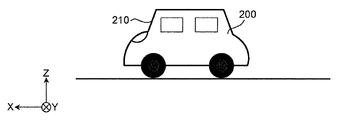
- the moving body is a vehicle such as an automobile and the display system is a head-up display (HUD) system for displaying display contents in front of the windshield of the vehicle will be described as an example.
- HUD head-up display
- FIG. 1 is a diagram for explaining the HUD system.
- the roll axis of the vehicle 200 is the X axis
- the pitch axis of the vehicle 200 is the Y axis
- the yaw axis of the vehicle 200 is the Z axis. That is, the X-axis is orthogonal to the Y-axis and the Z-axis, and is an axis along the line-of-sight direction of the occupant D who visually recognizes the displayed content Iv.
- the Y-axis is an axis along the left-right direction when viewed from the occupant D who visually recognizes the displayed content Iv.
- the Z axis is an axis along the height direction of the vehicle 200.
- the display system 100 of the present embodiment is a so-called augmented reality (AR) display in which the display content Iv is superimposed on the actual view in front of the windshield 210 of the vehicle 200.
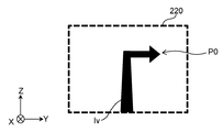
- the display content Iv is content indicating predetermined information displayed in the display area 220.
- the display content Iv is a figure and characters indicating a route for guiding to a destination, an estimated time of arrival at the destination, a traveling direction, a speed, various warnings, and the like.
- an arrow indicating a route for guiding to the destination will be described as an example of the display content Iv.
- the display system 100 is installed in the vehicle 200 and projects the display light Lc representing the display content Iv into the display area 220 of the windshield 210 of the vehicle 200.
- the display area 220 is a part of the windshield 210.
- the display area 220 may be the entire area of the windshield 210.
- the display light Lc is reflected in the vehicle interior direction by the windshield 210. As a result, the occupant D in the vehicle 200 visually recognizes the reflected display light Lc as the display content Iv in front of the vehicle 200.
- the display system 100 includes a projection device 10, an information acquisition device 20, a display processing device 30, a posture detection device 40, and a vibration correction processing device 50.
- the projection device 10 projects the display light Lc representing the display content Iv into the display area 220.
- the projection device 10 includes, for example, a liquid crystal display element that displays an image of display content Iv, a light source such as an LED that illuminates the liquid crystal display element, a mirror that reflects the display light Lc of the image displayed by the liquid crystal display element to the display area 220, and a mirror. Including lenses and the like.
- the projection device 10 is installed, for example, in the dashboard of the vehicle 200.
- the information acquisition device 20 acquires information indicating the position of the vehicle 200. Specifically, the information acquisition device 20 measures the position of the vehicle 200 and generates position information indicating the position. The information acquisition device 20 outputs vehicle-related information including the position information of the vehicle 200.
- the display processing device 30 controls the display of the display content Iv based on the vehicle-related information obtained from the information acquisition device 20, and outputs the image data of the display content Iv to the projection device 10.
- the display processing device 30 may control the display of the display content Iv based on the display timing (display time) of the display content Iv or the combination of the vehicle-related information and the display timing.
- the display timing is, for example, repeating display for 10 seconds and non-display for 1 second.
- the display processing device 30 performs image correction processing accompanied by changing the display position of the display content Iv based on the image correction data, and corrects the display deviation such as distortion and rotation deviation of the display content Iv.
- the posture detection device 40 detects the posture change of the vehicle 200. Specifically, the posture detecting device 40 detects the amount of change in the posture of the vehicle 200.
- the amount of change in attitude is the angular velocity.
- the attitude detection device 40 includes, for example, a gyro sensor 41 (see FIG. 2) that detects an angular velocity.
- the gyro sensor 41 outputs the detected angular velocity to the vibration correction processing device 50 as a posture change amount indicating the posture change of the vehicle 200.
- the vibration correction processing device 50 calculates the vibration correction amount of the display position of the display content Iv based on the posture change of the vehicle 200 detected by the posture detection device 40.
- the vibration correction processing device 50 outputs the calculated vibration correction amount to the display processing device 30.
- the display position of the display content Iv is corrected in the display area 220 according to the change in the actual view seen from the windshield 210.
- FIG. 2 is a block diagram showing the internal configuration of the display system 100.
- the information acquisition device 20 includes a GPS (Global Positioning System) module 21 that detects a position indicating the current location of the vehicle 200 in the geographic coordinate system. Specifically, the GPS module 21 receives radio waves from GPS satellites and determines the latitude and longitude of the received points. The GPS module 21 generates position information indicating the measured latitude and longitude. The information acquisition device 20 outputs vehicle-related information including position information to the display processing device 30.
- GPS Global Positioning System
- the display processing device 30 includes a communication unit 31, a display control unit 32, a storage unit 33, and an image correction unit 34.
- the communication unit 31 includes a circuit that communicates with an external device in accordance with a predetermined communication standard.
- Predetermined communication standards include, for example, LAN, Wi-Fi (registered trademark), Bluetooth (registered trademark), USB, HDMI (registered trademark), CAN (controller area network), SPI (Serial Peripheral Interface).
- the display control unit 32 can be realized by a semiconductor element or the like.
- the display control unit 32 can be composed of, for example, a microcomputer, a CPU, an MPU, a GPU, a DSP, an FPGA, and an ASIC.
- the function of the display control unit 32 may be configured only by hardware, or may be realized by combining hardware and software.
- the display control unit 32 realizes a predetermined function by reading data and programs stored in the storage unit 33 and performing various arithmetic processes.
- the display control unit 32 includes a processing switching unit 32a.
- the process switching unit 32a switches the order of processing between the image correction process and the vibration correction process.
- the image correction process is an image correction accompanied by a change in the display position of the display content Iv performed by the image correction unit 34.
- the vibration correction processing is a vibration correction that corrects the display position of the display content Iv based on the vibration correction amount calculated by the vibration correction processing device 50.
- the process switching unit 32a switches the order of processing between the image correction process and the vibration correction process based on a predetermined condition.
- the processing switching unit 32a acquires the image processing time Td of the image correction processing, and switches the order of processing between the image correction processing and the vibration correction processing based on the image processing time Td.
- the image processing time Td means the processing time required for changing the display position of the display content Iv by the image correction processing.
- the image processing time Td may be a predetermined value or a value that changes for each image correction processing target.
- the image processing time Td may be calculated based on the amount of information and / or the image correction value U of the display content Iv on which the image correction processing is performed.
- the processing switching unit 32a switches the order of processing so that the image correction processing is performed after the vibration correction processing is performed. Further, when the image processing time Td is larger than the first threshold value T1, the processing switching unit 32a switches the order of processing so that the vibration correction processing is performed after the image correction processing is performed.
- the storage unit 33 is a storage medium for storing programs and data necessary for realizing the functions of the display processing device 30.
- the storage unit 33 can be realized by, for example, a hard disk (HDD), SSD, RAM, DRAM, ferroelectric memory, flash memory, magnetic disk, or a combination thereof.
- the storage unit 33 stores a plurality of image data 33i representing the display content Iv. Further, the storage unit 33 stores the image correction data 33g used for the image correction processing.
- the image correction data 33g includes, for example, an image correction value for correcting display deviation such as distortion and / or rotation deviation of an image representing display content Iv.
- the image correction value is known data calculated based on, for example, image distortion and / or rotation deviation measured by inspection at the time of manufacture of the display system 100, and is a static value.
- the distortion is, for example, distortion that occurs when the display content Iv is reflected by the windshield 210 when the display content Iv is displayed in front of the windshield 210 of the vehicle 200.
- the rotation deviation is a deviation caused by a variation in installation, for example, when the projection device 10 is installed at an angle with respect to the windshield 210 on which light is projected from the projection device 10.
- the image correction data 33g may divide the display area 220 into a plurality of division areas and store the image correction value assigned to each of the plurality of division areas.
- the image correction data 33g may store an image correction table showing image correction values assigned to each of the plurality of partition areas.
- the image correction data 33g may include an image correction value for correcting a display deviation that causes a change in the display position of the display content Iv other than distortion and / or rotation deviation.
- the image correction unit 34 performs image correction processing accompanied by a change in the display position of the display content Iv based on the image correction data 33g stored in advance in the storage unit 33.
- the image correction process accompanied by the change of the display position of the display content Iv includes, for example, correction of distortion of the image and / or correction of rotation deviation of the image.
- the image correction unit 34 corrects distortion and / or rotation deviation of the display content Iv projected on the windshield 210 of the vehicle 200 by the projection device 10.
- the image correction unit 34 reads out the image correction data 33g stored in advance in the storage unit 33, and determines an image correction value for correcting the display deviation of the display position of the display content Iv caused by distortion and / or rotation deviation. ..
- the image correction unit 34 determines the image correction value using the image correction table of the image correction data 33g.
- the image correction value determined by the image correction unit 34 is output to the display control unit 32.
- the image correction unit 34 may be included in the display control unit 32.
- the display control unit 32 determines the display content Iv to be displayed in the display area 220 based on the vehicle-related information obtained from the information acquisition device 20.
- the display control unit 32 reads the image data 33i of the determined display content Iv from the storage unit 33 and outputs the image data 33i to the projection device 10.
- the display control unit 32 acquires information indicating the display reference position from an external device (not shown) via the communication unit 31.
- the display reference position is a position that serves as a reference for displaying the display content Iv in the display area 220.
- the display control unit 32 acquires content information indicating information on the display content Iv.
- the content information includes, for example, information such as the shape, size, display edge, and display reference position of the display content Iv.
- information on display content including display reference position and content information (for example, information such as size of display content) is referred to as content display information.
- the content display information includes at least a feature portion that determines the shape of the displayed content.
- the feature portion is, for example, a pixel position of a content display.
- the content display information is stored in the storage unit 33 together with the image data 33i.
- the display control unit 32 acquires vehicle-related information from the information acquisition device 20 via the communication unit 31, and uses the images to be used among the plurality of image data 33i stored in the storage unit 33 based on the vehicle-related information. Determine the data. As a result, the display control unit 32 acquires information indicating the shape, size, display end, and the like of the display content Iv.
- the display control unit 32 outputs the content display information to the vibration correction processing device 50.
- the display control unit 32 acquires the image correction value of the display content Iv from the image correction unit 34, and changes the display position of the display content Iv based on the image correction value. Further, the display control unit 32 acquires the vibration correction amount from the vibration correction processing device 50. The display control unit 32 sets the display position of the display content Iv based on the display reference position and the vibration correction amount.
- the attitude detection device 40 includes a gyro sensor 41 that detects an angular velocity.
- the gyro sensor 41 outputs the detected angular velocity to the vibration correction processing device 50 as a posture change amount indicating the posture change of the vehicle 200.
- the calculation processing of the output of the posture detection device 40 may be performed by the deviation amount calculation unit 52a of the posture detection device 40 or the vibration correction processing device 50, or another configuration.
- the vibration correction processing device 50 includes a communication unit 51, a correction control unit 52, and a storage unit 53.
- the communication unit 51 includes a circuit that communicates with an external device in accordance with a predetermined communication standard.
- Predetermined communication standards include, for example, LAN, Wi-Fi (registered trademark), Bluetooth (registered trademark), USB, HDMI (registered trademark), CAN (controller area network), SPI (Serial Peripheral Interface).
- the correction control unit 52 can be realized by a semiconductor element or the like.
- the correction control unit 52 can be composed of, for example, a microcomputer, a CPU, an MPU, a GPU, a DSP, an FPGA, and an ASIC.
- the function of the display control unit 32 may be configured only by hardware, or may be realized by combining hardware and software.
- the correction control unit 52 realizes a predetermined function by reading data or a program stored in a storage unit (not shown) in the vibration correction processing device 50 and performing various arithmetic processing.
- the correction control unit 52 includes a deviation amount calculation unit 52a and a correction amount calculation unit 52b as functional configurations.
- the deviation amount calculation unit 52a calculates the attitude (angle deviation amount) of the vehicle 200 based on the attitude change amount output by the attitude detection device 40.
- the amount of deviation of the angle is the posture angle with respect to the posture state that is the reference of the moving body.
- the reference posture state of the moving body is, for example, a stationary vehicle state placed in a horizontal state.
- the deviation amount calculation unit 52a calculates the angle (pitch angle) around the pitch axis of the vehicle 200 by integrating the angular velocity detected by the gyro sensor 41. Thereby, the deviation amount (angle) of the vehicle 200 in the rotation direction about the Y axis (pitch axis) shown in FIG. 1 can be calculated.
- the pitch angle is calculated, but the yaw angle or the roll angle may be calculated.
- all angles around the X-axis, Y-axis, and Z-axis may be calculated.
- the pitch angle, the yaw angle, and the roll angle are 0 °, respectively.
- the amount of deviation which is an angle with respect to the three axial directions, may be calculated.
- the posture detection device 40 outputs the pitch angle, yaw angle, and roll angle, these values may be processed as a deviation amount, or may be processed as a deviation amount by performing arithmetic processing other than integration. good.
- the correction amount calculation unit 52b calculates the correction amount (vibration correction amount) of the display position of the display content Iv based on the posture (angle deviation amount) of the vehicle 200.
- the correction amount is indicated by, for example, the number of pixels in the Y-axis direction and the Z-axis direction.
- the correction amount calculation unit 52b converts, for example, the deviation amount of the pitch angle and the yaw angle calculated by the deviation amount calculation unit 52a from the angle into the number of pixels, and based on the number of pixels corresponding to the deviation. Determine the amount of correction to be returned.
- the correction amount calculation unit 52b determines a correction amount for the roll angle so as to restore the deviation amount of the roll angle while keeping the angle.
- the correction amount calculation unit 52b outputs the calculated correction amount to the display processing device 30.
- the display processing device 30 and the vibration correction processing device 50 communicate in both directions by the communication units 31 and 51.
- the display processing device 30 outputs the content display information to the vibration correction processing device 50.
- the vibration correction processing device 50 outputs correction information indicating a vibration correction amount to the display processing device 30.
- FIG. 3A shows an example when the vehicle 200 is not tilted.
- FIG. 3B shows an example of an actual view seen from the windshield 210 of the vehicle 200 shown in FIG. 3A.
- FIG. 3C shows an example of the display content Iv visible from the display area 220.
- FIG. 3D shows an example in which the display content Iv shown in FIG. 3C is displayed so as to overlap with the actual scene shown in FIG. 3B.
- the display system 100 superimposes the display content Iv shown in FIG. 3C on the actual scene shown in FIG. 3B.
- the display reference position P0 of the display content Iv is a position determined based on the type of the display content Iv, the state (position and posture) of the vehicle 200, the map data, and the like. For example, when the display target 230 is a traveling lane and the display content Iv is an arrow indicating a traveling direction, the display reference position P0 is a display position on the liquid crystal display when the tip of the arrow points to the center of the traveling lane.
- the display reference position P0 is set, for example, in FIG. 3C at the position of the pixel on the liquid crystal display corresponding to the values of the Y coordinate and the Z coordinate in the display area 220.
- the display reference position P0 is acquired from an external device.
- the external device can be composed of, for example, a microcomputer, a CPU, an MPU, a GPU, a DSP, an FPGA, or an ASIC, and a GPS module 21.
- the function of the external device may be configured only by hardware, or may be realized by combining hardware and software.
- the display reference position P0 output from the external device may change based on the change in posture due to the number of occupants, the change in load, the decrease in gasoline, etc., so for example, when it is different from the display reference position initially acquired. There is. Therefore, the display processing device 30 may change the display reference position P0 acquired from the external device based on the change in posture due to the number of occupants, the change in load, the decrease in gasoline, and the like.
- the display processing device 30 may set the display reference position P0 based on vehicle-related information, map data, and the like.
- the display processing device 30 may set the size of the display content Iv based on the vehicle-related information.
- FIG. 4A shows an example of a state in which the vehicle 200 is in a forward leaning posture.
- FIG. 4B illustrates a case where the display position of the display content Iv deviates from the display target 230 according to the posture change of the vehicle 200.
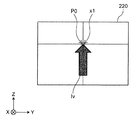
- FIG. 4C shows the display position of the display content Iv after vibration correction.
- the vehicle 200 may tilt due to unevenness of the road surface, sudden acceleration or deceleration of the vehicle 200, or the like. For example, when the vehicle 200 suddenly decelerates, the vehicle 200 is in a forward leaning posture as shown in FIG. 4A. In this case, as shown in FIG. 4B, the position of the display target 230 seen from the windshield 210 changes according to the inclination of the vehicle 200. Therefore, when the display content Iv is displayed at the display reference position P0, the display content Iv deviates from the display target 230. For example, as shown in FIG. 4B, the tip of the arrow is in the oncoming lane 231.
- the display system 100 adjusts the display position of the display content Iv in the direction of returning the deviation according to the posture of the vehicle 200.
- the vibration correction processing device 50 calculates the vibration correction amount C so that the position P1 has no deviation of the display position due to the angle of the vehicle 200. That is, the display processing device 30 sets the display position of the display content Iv to "display reference position P0 + vibration correction amount C". As a result, the projection device 10 can display the display content Iv at the position P1 corresponding to the display target 230.
- the position P1 corresponding to the display target 230 in the actual scene is changed.
- the display content Iv can be displayed in.
- FIG. 5 shows an image diagram for explaining the image correction process.
- a distortion correction process when distortion occurs in the vertical direction of the display area 220 will be described.
- the sizes of the plurality of compartment areas differ due to distortion.
- the sizes of the upper regions L11 and L12 and the lower regions L15 and L16 are smaller than those in the case where there is no distortion.
- the sizes of the central regions L13 and L14 are larger than those of the compartmentalized region when there is no distortion.
- the size of the display contents Iv11 to Iv16 displayed in each section area changes, and the display positions P11 to P16 at the tips of the arrows, which are characteristic portions of the display contents Iv11 to Iv16, deviate from the superimposed positions Q11 to Q16.
- the image correction unit 34 performs image correction processing accompanied by a change in the display position of the display content Iv based on the image correction data 33g stored in advance in the storage unit 33. Specifically, the image correction unit 34 determines the image correction value using the image correction table of the image correction data 33g, and outputs the image correction value to the display control unit 32. In the example shown in FIG. 5, the image correction unit 34 determines the image correction value so that the display contents Iv11, Iv12 and Iv15, Iv16 become larger in the vertical direction in the upper regions L11, L12 and the lower regions L15, L16. ..
- the image correction unit 34 determines the image correction value so that the display contents Iv13 and Iv14 become smaller in the vertical direction in the central regions L13 and L14.
- the display control unit 32 can control the display positions P11 to P16 of the display contents Iv11 to Iv16 based on the determined image correction value and superimpose the display contents on the superimposed positions Q11 to Q16.
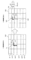
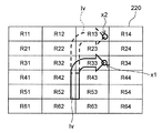
- FIG. 6A shows an example of a plurality of compartment areas R11 to R64 in the display area 220.
- the display area 220 on which the display content Iv is displayed has a plurality of partition areas R11 to R64.
- the plurality of partition areas R11 to R64 are partitioned vertically and horizontally in a mesh shape.
- the display area 220 is divided into six vertical and four horizontal division areas R11 to R64.
- the number and arrangement of the partition areas are not limited to this.
- the display area 220 may have a plurality of compartment areas.
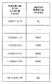
- FIG. 6B shows an example of image correction data 33 g.
- the image correction data 33g has an image correction table including image correction values U11 to U64 assigned to each of the plurality of partition areas R11 to R64 of the display area 220.
- the image correction values U11 to U64 of the image correction data 33g correspond to a plurality of division areas R11 to R64 of the display area 220, respectively.
- the image correction value U22 is adopted as the image correction value.
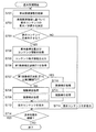
- FIG. 7 shows the display processing performed by the display control unit 32 of the display processing device 30.
- the display process shown in FIG. 7 is started, for example, when the engine of the vehicle 200 is started, or when the button for instructing the display start of the display content Iv is operated.
- the display control unit 32 acquires vehicle-related information including the position information of the vehicle 200 from the information acquisition device 20 (S101). The display control unit 32 determines whether or not to display the display content Iv corresponding to the display target 230 based on the vehicle-related information (S102).
- the display control unit 32 decides to display the display content Iv (Yes in S103)
- the display control unit 32 acquires the information indicating the display reference position P0 of the display content Iv from the external device and also acquires the content information from the storage unit 33. (S104).
- the display control unit 32 outputs the content display information to the vibration correction processing device 50 (S105).
- the content display information includes a display reference position and content information.
- the display control unit 32 acquires the image processing time Td (S106). For example, the processing switching unit 32a of the display control unit 32 calculates the image processing time Td based on the display reference position P0, the content information, and the image correction value U. It should be noted that the approximate value of the image processing time Td may be stored in advance in the content information. In this case, the display control unit 32 may use the estimated value stored in the content information as it is as the image processing time Td, or may calculate the image processing time Td based on the estimated value.
- the processing switching unit 32a switches the order of processing between the image correction processing and the vibration correction processing based on the image processing time Td. In the present embodiment, the processing switching unit 32a switches the order of processing between the image correction processing and the vibration correction processing based on the image processing time Td and the first threshold value T1.
- the processing switching unit 32a determines whether or not the image processing time Td is equal to or less than the first threshold value T1 (S107). When the image processing time Td is equal to or less than the first threshold value T1 (Yes in S107), the processing switching unit 32a switches the order of processing so that the image correction processing is performed after the vibration correction processing is performed. That is, when the image processing time Td is equal to or less than the first threshold value T1, the display processing apparatus 30 first performs vibration correction processing (S108). The display processing device 30 performs the image correction processing after performing the vibration correction processing (S109).
- the processing switching unit 32a switches the order of processing so that the vibration correction processing is performed after the image correction processing is performed. That is, when the image processing time Td is larger than the first threshold value T1, the display processing apparatus 30 performs the image correction processing (S110). The display processing device 30 performs the vibration correction processing after performing the image correction processing (S111).
- FIG. 8 shows the vibration correction processing performed by the display control unit 32 of the display processing device 30.
- the vibration correction process shown in FIG. 8 shows the details of steps S108 and S111 shown in FIG. 7.
- the display processing device 30 acquires the vibration correction amount C from the vibration correction processing device 50 (S120).
- the display control unit 32 changes the setting of the display position of the display content Iv based on the display reference position P0, the content information, and the vibration correction amount C (S121).
- the display control unit 32 reads out the image data 33i of the display content Iv corresponding to the display target from the storage unit 33 and displays it.
- the display position of the content Iv is set to "display reference position P0 + vibration correction amount C".
- the display control unit 32 reads the image data 33i of the display content Iv from the storage unit 33 and "displays" the image corrected based on the image correction value U. Set to "reference position P0 + vibration correction amount C".
- the display control unit 32 reads the image data 33i of the display content Iv from the storage unit 33, and the image is based on the image correction value U.
- the corrected image is set to "display reference position P0".
- the display control unit 32 reads the image data 33i of the display content Iv from the storage unit 33, and sets the read image into "display reference position P0 + vibration correction amount C". Set.
- the image correction process is performed based on the image correction value U at the position of the image changed in the vibration correction process.
- FIG. 9 shows an image correction process performed by the display control unit 32 of the display processing device 30.
- the image correction process shown in FIG. 9 shows the details of steps S109 and S110 shown in FIG. 7.
- the display control unit 32 acquires information indicating the image correction value U of the display content Iv from the image correction unit 34 (S130).
- the display control unit 32 changes the setting of the display position of the display content Iv based on the display reference position P0, the content information, and the image correction value U (S131). For example, the display control unit 32 corrects all the areas R11 to R64 in the display area 220 by using the image correction values U11 to U64 to enlarge, reduce, and / or rotate the image.
- the display control unit 32 sets the display position of the display content Iv to the display reference position P0 after performing the image correction.
- the display control unit 32 After performing the vibration correction process and the image correction process, the display control unit 32 displays the display content Iv (S112).
- the display control unit 32 decides not to display the display content Iv (No in S103), the display control unit 32 hides the display content Iv (S113).
- the display control unit 32 determines whether or not to continue the display process (S114). For example, when the engine of the vehicle 200 is stopped, or when the button for instructing the end of the display of the display content Iv is operated, the display control unit 32 ends the display process. To continue the display process, the process returns to step S101.
- FIG. 10 shows a calculation process of the vibration correction amount C performed by the correction control unit 52 of the vibration correction processing device 50.
- the calculation process shown in FIG. 10 is started, for example, when the engine of the vehicle 200 is started, or when the button for instructing the display start of the display content Iv is operated.
- the calculation process of FIG. 10 is started together with the display process of FIG. 7, for example.
- the calculation process shown in FIG. 10 may be started when the button for instructing the start of the position correction of the display content Iv is operated.
- the correction control unit 52 acquires the content display information of the display content Iv from the display processing device 30 (S201).
- the correction control unit 52 acquires a posture change amount indicating the angular velocity of the vehicle 200 output from the gyro sensor 41 (S202).
- the correction control unit 52 calculates the posture of the vehicle 200, that is, the deviation amount y with respect to the three axial directions, based on the posture change amount (S203).
- the correction control unit 52 calculates the vibration correction amount C based on the deviation amount y calculated based on the posture change amount (S204). For example, the correction control unit 52 determines a vibration correction amount C that restores the deviation amount y of the pitch angle.
- the correction control unit 52 outputs the information of the vibration correction amount C to the display processing device 30 (S205).
- the correction control unit 52 determines whether or not to continue the calculation process (S206). For example, when the engine of the vehicle 200 is stopped, or when the button for instructing the end of the display of the display content Iv is operated, the correction control unit 52 ends the calculation process. If the calculation process is to be continued, the process returns to step S201.
- the correction control unit 52 calculates the vibration correction amount C of the display position of the display content Iv based on the posture change amount.
- the display system 100 of the present disclosure includes a display processing device 30, an image correction unit 34, a posture detection device 40, a vibration correction processing device 50, and a processing switching unit 32a.
- the display processing device 30 controls the display of the display content Iv.
- the image correction unit 34 performs image correction processing accompanied by a change in the display position of the display content Iv based on the image correction data 33g stored in advance.
- the posture detection device 40 detects the amount of change in posture of the moving vehicle 200.
- the vibration correction processing device 50 calculates the vibration correction amount C of the display position of the display content Iv based on the posture change amount of the moving body.
- the processing switching unit 32a switches the order of processing of image correction processing that involves changing the display position of the display content Iv and vibration correction processing that corrects the display position of the display content Iv based on the vibration correction amount C.
- the display processing device 30 controls the display position of the display content Iv by performing the image correction processing and the vibration correction processing based on the order of the processing switched by the processing switching unit 32a.
- the processing switching unit 32a acquires the image processing time Td of the image correction processing.
- the processing switching unit 32a switches the order of processing between the image correction processing and the vibration correction processing based on the image processing time Td.
- the order of processing can be optimized according to the driving situation, so that the accuracy of vibration correction processing and image correction processing can be compatible and the superimposition performance and quality can be improved.
- the image processing time Td increases. For example, when there is a lot of content to be displayed (for example, when the moving object is traveling in the city area), the image processing time Td is long, and when there is little content to be displayed (for example, the moving object is traveling on the highway). Case), the image processing time Td may be shortened. Therefore, by switching the order of processing between the image correction processing and the vibration correction processing based on the image processing time Td, the optimum processing can be performed according to the traveling condition of the moving body.
- the delay time of the vibration correction processing can be shortened and the vibration correction error can be suppressed by performing the vibration correction processing after the image correction processing.
- the image processing time Td is small, the accuracy of the image correction processing can be improved by performing the image correction processing after the vibration correction processing.
- the vibration correction processing and the image correction processing can be performed in the order of the optimum processing based on the image processing time Td.
- the image processing time Td also changes. For example, when the amount of information of the display content Iv increases, the image processing time Td becomes long, and the delay time due to the vibration correction processing may become long. In this case, if the image correction process is performed after the vibration correction process is performed, the vibration correction error becomes large.
- the display system 100 since the order of processing between the vibration correction processing and the image correction processing can be switched based on the image processing time Td, the display content is displayed even when the display content Iv is updated and the amount of information changes. It is possible to suppress a decrease in the correction accuracy of the Iv display position.
- the processing switching unit 32a switches the order of processing so that the image correction processing is performed after the vibration correction processing is performed.
- the processing switching unit 32a switches the order of processing so that the vibration correction processing is performed after the image correction processing is performed.
- the present invention is not limited to this.
- the processing switching unit 32a may not be included in the display control unit 32.
- the processing switching unit 32a may switch the order of processing between the image correction processing and the vibration correction processing based on the image processing time Td of the image correction processing.
- the processing switching unit 32a may switch the order of processing between the image correction processing and the vibration correction processing based on the traveling condition of the moving body.
- the processing switching unit 32a may be the delay time from the correction to the display or the amount of increase thereof when the vibration correction processing is performed after the image correction processing. In this way, the processing switching unit 32a may switch the processing order based on information other than the image processing time Td.
- the order of the vibration correction processing and the image correction processing is switched based on the image processing time Td of the image correction processing.
- the order of the vibration correction processing and the image correction processing is switched based on whether or not a specific frequency vibration is generated.
- FIG. 11 shows a block diagram showing an internal configuration of the display system 100A according to the second embodiment.
- the display system 100A shown in FIG. 11 differs from the display system 100 of the first embodiment in that the correction control unit 52A includes a vibration detection unit 52c.
- the display system 100A shown in FIG. 11 other configurations are the same as the configuration of the display system 100 of the first embodiment.
- the vibration detection unit 52c detects whether or not the input signal contains a specific frequency band component.
- the specific frequency band component is a high frequency band component.
- the vibration detection unit 52c detects whether or not the input signal contains a high frequency band component equal to or higher than a predetermined frequency band.
- the vibration detection unit 52c includes a fluctuation amount calculation unit 52m, an offset removal filter 52e, a threshold cross detection unit 52f, a counter 52g, and a vibration determination unit 52h.
- the fluctuation amount calculation unit 52m calculates the fluctuation amount of the vehicle 200 based on the posture change amount output by the posture detection device 40. For example, the fluctuation amount calculation unit 52m calculates the angle (pitch angle) around the pitch axis of the vehicle 200 by integrating the pitch angular velocity detected by the gyro sensor 41 as the fluctuation amount. Thereby, the amount of fluctuation (pitch angle) of the vehicle 200 in the rotation direction about the Y axis (pitch axis) shown in FIG. 1 can be detected. In this embodiment, the pitch angle is calculated, but the yaw angle or the roll angle may be calculated. For example, all angles around the X-axis, Y-axis, and Z-axis may be calculated. Since both the deviation amount calculated by the deviation amount calculation unit 52a and the fluctuation amount calculated by the fluctuation amount calculation unit 52m are angle information, they may be shared or calculated as separate angle information. ..
- the offset removal filter 52e removes the offset component of the input signal (variation amount), and as a result, attenuates the low frequency band component of the input signal.
- the offset removal filter 52e is, for example, a high-pass filter.
- the relationship between the cutoff frequency Fc of the offset removal filter 52e and the frequency band lower limit F to be detected satisfies, for example, the following equation (1).
- Equation T is the total delay time (time lag) [sec] from the calculation of the correction amount of the virtual image to the display.
- the frequency setting method is not limited to the equation (1) and may be adjusted as appropriate.
- the threshold cross detection unit 52f detects that the input value straddles a predetermined threshold.
- detecting that the threshold value is crossed means, for example, detecting that the input value has changed from less than the threshold value to more than the threshold value or from more than the threshold value to less than the threshold value.
- the threshold cross detection unit 52f detects that the threshold is crossed, the threshold cross detection unit 52f outputs a detection signal to the counter 52g.
- the threshold is, for example, zero or any particular value.
- the arbitrary specific value is, for example, the value of the offset error.
- the counter 52g measures the number of times that the input value to the threshold cross detection unit 52f straddles a predetermined threshold. That is, the counter 52g counts the number of detection signals input from the threshold cross detection unit 52f to the counter 52g.
- the vibration determination unit 52h determines whether or not a specific frequency band component is generated for a certain period of time or more in the fluctuation amount based on the number of times measured by the counter 52g per unit time.
- the vibration determination unit 52h for example, provides a time window and determines the occurrence of vibration having a specific frequency band component based on the amount of change in the count value in a fixed time.
- the determination result is sent from the vibration determination unit 52h to the correction amount calculation unit 52b.
- the vibration determination unit 52h determines whether or not the high frequency band component is generated in the fluctuation amount for a certain period of time or more based on the number of times measured by the counter 52g per unit time.
- FIG. 12 shows the display processing performed by the display control unit 32 of the display processing device 30.
- Steps S301 to S305 and S308 to S314 of FIG. 12 are the same as steps S101 to S105 and S108 to S114 of FIG. 7 of the first embodiment.
- the display control unit 32 acquires vehicle-related information including the position information of the vehicle 200 from the information acquisition device 20 (S301). The display control unit 32 determines whether or not to display the display content Iv corresponding to the display target 230 based on the vehicle-related information (S302).
- the display control unit 32 decides to display the display content Iv (Yes in S303)
- the display control unit 32 acquires the information indicating the display reference position P0 of the display content Iv from the external device and also acquires the content information from the storage unit 33. (S304).
- the display control unit 32 outputs the content display information to the vibration correction processing device 50A (S305).
- the content display information includes a display reference position and content information.
- the display control unit 32 acquires the generation detection result of vibration having a high frequency band component (S306).
- the processing switching unit 32a of the display control unit 32 acquires the generation detection result of vibration having a high frequency band component from the vibration correction processing device 50A.
- the display control unit 32 acquires a signal indicating that vibration of a specific frequency is generated, which is output from the vibration correction processing device 50A.
- the display control unit 32 recognizes that vibration of a specific frequency is generated.
- the display control unit 32 does not receive the signal from the vibration correction processing device 50A, the display control unit 32 recognizes that vibration of a specific frequency has not occurred.
- the processing switching unit 32a switches the order of processing between the image correction processing and the vibration correction processing based on the detection result of vibration at a specific frequency. In the present embodiment, the processing switching unit 32a determines whether or not vibration having a high frequency band component is generated for a certain period of time or longer (S307). The processing switching unit 32a switches the order of processing between the image correction processing and the vibration correction processing based on the determination of whether or not vibration having a high frequency band component is generated for a certain period of time or longer.
- the processing switching unit 32a switches the processing order so that the image correction processing is performed after the vibration correction processing is performed. That is, when it is not detected that vibration having a high frequency band component is generated for a certain period of time or longer, the display processing apparatus 30 first performs vibration correction processing (S308). The display processing device 30 performs the image correction processing after performing the vibration correction processing (S309).
- the processing switching unit 32a switches the processing order so that the vibration correction processing is performed after the image correction processing is performed. That is, when it is detected that vibration having a high frequency band component is generated for a certain period of time or longer, the display processing apparatus 30 performs image correction processing (S310). The display processing device 30 performs the vibration correction processing after performing the image correction processing (S311).
- the vibration correction process may be the same as the vibration correction process of the first embodiment shown in FIG.
- the image correction process may be the same as the image correction process of the first embodiment shown in FIG.
- the display control unit 32 After performing the vibration correction process and the image correction process, the display control unit 32 displays the display content Iv (S312).
- the display control unit 32 decides not to display the display content Iv (No in S303), the display control unit 32 hides the display content Iv (S313).
- the display control unit 32 determines whether or not to continue the display process (S314). To continue the display process, the process returns to step S301.
- FIG. 13 shows the calculation processing of the vibration correction amount C performed by the correction control unit 52A of the vibration correction processing device 50A in the second embodiment.
- Steps S401 to S403 and S406 to S408 of FIG. 13 are the same as steps S201 to S206 of FIG. 10 of the first embodiment.
- the correction control unit 52A acquires the content display information of the display content Iv from the display processing device 30 (S401).
- the correction control unit 52A acquires a posture change amount indicating the angular velocity of the vehicle 200 output from the gyro sensor 41 (S402).
- the correction control unit 52A calculates the posture of the vehicle 200, that is, the deviation amount y with respect to the three axial directions, based on the acquired posture change amount (S403).
- the deviation amount calculation unit 52a calculates the pitch angle of the vehicle 200 by integrating the angular velocity.
- the calculated deviation amount y is sent to the correction amount calculation unit 52b.
- the fluctuation amount calculation unit 52m of the vibration detection unit 52c of the correction control unit 52A calculates the posture of the vehicle 200, for example, the fluctuation amount which is an angle with respect to the pitch direction, based on the acquired posture change amount (S404). Specifically, the fluctuation amount calculation unit 52m calculates the pitch angle of the vehicle 200 by integrating the angular velocity. The calculated fluctuation amount is sent to the offset removal filter 52e. The amount of fluctuation may be calculated after the offset is removed.
- the offset removal filter 52e of the vibration detection unit 52c removes the detected offset component of the fluctuation amount, and as a result, the low frequency band component of the fluctuation amount is also attenuated. For example, when the fluctuation amount fluctuates as shown in FIG. 14A (a), the offset removal filter 52e removes the offset component OF1 included in the fluctuation amount to obtain a 0 value as shown in FIG. 14A (b). The amount of fluctuation that vibrates with the center of the amplitude can be obtained. The amount of fluctuation in which the offset component OF1 is removed and the low frequency band component is attenuated is sent to the threshold cross detection unit 52f.
- the threshold cross detection unit 52f detects that the input fluctuation amount crosses a predetermined threshold. For example, when the fluctuation amount fluctuates as shown in FIG. 14B (a), the threshold cross detection unit 52f detects, for example, that the threshold value has changed from less than zero value to more than zero value, and FIG. 14B ( As shown in b), the detection signal is output to the counter 52g.
- the threshold cross detection unit 52f halves the detection cycle and counts the decrease change from zero value or more to less than zero value in addition to the increase change from less than zero value to zero value or more, which is the threshold value. You may.
- the counter 52g measures the number of detection signals input in a predetermined period.
- the predetermined period may be, for example, a form such as a time window, or the latest predetermined time.
- the vibration determination unit 52h determines whether or not vibration having a high frequency band component is generated in the fluctuation amount (S405).
- the vibration determination unit 52h determines, for example, whether or not the fluctuation amount includes a high frequency band component by comparing the number of times the fluctuation amount crosses the threshold value with the count threshold value within a predetermined period.
- the vibration determination unit 52h compares the number of times the counter 52g has counted with the count threshold value.
- the vibration determination unit 52h determines that the number of times the counter 52g has counted is smaller than the count threshold, it determines that the fluctuation amount does not include the high frequency band component for a certain period of time or longer, and the vibration of the vehicle 200 has a high frequency based on this determination result. Recognize that vibration with band components is not included.
- the vibration determination unit 52h determines that the number of times the counter 52g has counted is equal to or greater than the count threshold value, the vibration determination unit 52h recognizes that the fluctuation amount includes vibration having a high frequency band component.
- the correction control unit 52A outputs the generation detection result of vibration having a high frequency band component to the display processing device 30 (S405). Specifically, when vibration having a high frequency band component is generated, a signal indicating that vibration having a high frequency band component is generated is sent to the display processing device 30.
- the correction control unit 52A calculates the vibration correction amount C based on the deviation amount y calculated based on the posture change amount (S407). For example, the correction control unit 52A determines a vibration correction amount C that restores the deviation amount y of the pitch angle.
- the correction control unit 52A outputs the information of the vibration correction amount C to the display processing device 30 (S408).
- the correction control unit 52A determines whether or not to continue the calculation process (S409). For example, when the engine of the vehicle 200 is stopped, or when the button for instructing the end of the display of the display content Iv is operated, the correction control unit 52A ends the calculation process. To continue the calculation process, the process returns to step S401.
- the display system 100A of the present embodiment includes a vibration detection unit 52c that detects that vibration having a specific frequency band component is generated for a certain period of time or longer in the posture change of the moving body.
- the process switching unit 32a switches the order of processing between the image correction process and the vibration correction process based on the detection result of the vibration detection unit 52c.
- Vibration having a specific frequency band component is high frequency vibration having a high frequency band component.
- the processing switching unit 32a switches the order of processing so that the vibration correction processing is performed after the image correction processing is performed when the vibration having the high frequency band component is generated for a certain period of time or longer. Further, the processing switching unit 32a switches the order of processing so that the image correction processing is performed after the vibration correction processing is performed when the vibration having the high frequency band component is not generated for a certain period of time or more.
- the allowable delay time of vibration correction processing for the target superimposition accuracy differs depending on the vibration frequency.
- the delay time of the vibration correction process means the time from the calculation of the vibration correction amount to the display. For example, the higher the vibration frequency, the shorter the allowable delay time of the vibration correction process in order to suppress the vibration correction error to a certain level or less. Therefore, it is detected that vibration having a high frequency band component higher than a specific frequency band is generated in the posture fluctuation of the moving body for a certain period of time or longer, and the image correction process and the vibration correction process are performed according to the detection result.
- the optimum processing can be performed according to the traveling condition of the moving body. For example, when vibration having a high frequency band component is generated for a certain period of time or longer, the delay time of the vibration correction process is shortened and the band on the high frequency side that can be corrected is expanded by performing the vibration correction process after the image correction process. It is possible to suppress the vibration correction error. When vibration having a high frequency band component has not occurred for a certain period of time or more, the accuracy of the image correction processing can be improved by performing the image correction processing after the vibration correction processing.
- vibration is performed in the order of optimum processing based on the detection result of vibration having a high frequency band component. Correction processing and image correction processing can be performed.
- the frequency band and amplitude of the vibration generated by the track conditions vary variously, for example, when applying a filter process such as a high-pass filter, a low-pass filter, or a band-pass filter, the amplitude of the vibration must be used as a criterion. It must be, but it is difficult to predict the amplitude of the vibration. It is difficult to set the optimum threshold value for filtering.
- the high frequency component is detected by the counter value, it is not necessary to include the vibration amplitude in the determination standard, and the high frequency band can be detected with high accuracy.
- the vibration detection unit 52c includes a fluctuation amount calculation unit 52m, an offset removal filter 52e, a threshold cross detection unit 52f, a counter 52g, and a vibration determination unit 52h has been described. Not limited to.
- the vibration detection unit 52c may detect that vibration having a specific frequency band component is generated for a certain period of time or longer.
- the vibration correction amount C may be set to "0".
- the specific frequency vibration is a vibration having a high frequency band component
- the specific frequency vibration may be a vibration having a low frequency band component below a predetermined frequency band.
- the processing switching unit 32a may switch the order of the vibration correction processing and the image correction processing based on whether or not the vibration having the low frequency band component is generated for a certain period of time or longer. Specifically, when the vibration having a low frequency band component is generated for a certain period of time or longer, the processing switching unit 32a may perform the image correction processing after performing the vibration correction processing. When the processing switching unit 32a does not generate vibration having a low frequency band component for a certain period of time or longer, the processing switching unit 32a may perform the vibration correction processing after performing the image correction processing.
- the vibration correction amount C is calculated based on the deviation amount regardless of the order of processing.
- the vibration correction amount C is calculated based on the deviation amount, and when the vibration correction processing is performed after the image correction processing, the deviation amount and the image correction error are set. Based on this, the vibration correction amount C is calculated. Further, in the present embodiment, the calculation process of the vibration correction amount C is switched based on the image processing time Td.
- FIG. 15 shows a block diagram showing an internal configuration of the display system 100B according to the third embodiment.
- the display system 100B shown in FIG. 15 is different from the display system 100 of the first embodiment in that the correction control unit 52B includes an image correction error calculation unit 52d.
- the display system 100B shown in FIG. 15 other configurations are the same as the configuration of the display system 100 of the first embodiment.
- the image correction error calculation unit 52d calculates the image correction error of the image correction process caused by the vibration correction process for correcting the display deviation caused by the posture change of the vehicle 200. Specifically, the image correction error calculation unit 52d calculates the initial position of the display content Iv based on the content display information output from the display processing device 30.
- the initial position means the display position of the display content Iv when the vibration correction amount is “0”.
- the initial position may be a display reference position first acquired from an external device, or may be a position of a feature portion of the display content Iv when the vibration correction amount is “0”.
- the initial position is the display position of the characteristic portion of the display content Iv when the vibration correction amount is "0".
- the feature portion is the tip portion of the arrow.
- the initial position is the display position of the tip of the arrow.
- FIG. 16A is a diagram showing an example of the initial position x1 of the display content Iv.
- the display content Iv shown in FIG. 16A is an arrow having a linear shape extending in one direction.
- the initial position x1 of the display content Iv coincides with the display reference position P0 which is the display position of the display content Iv when the vibration correction amount is “0”.
- FIG. 16B is a diagram showing another example of the initial position x1 of the display content Iv.
- the display content Iv shown in FIG. 16B is an arrow having a shape bent by 90 °.
- the initial position x1 of the display content Iv is different from the display reference position P0.
- the image correction error calculation unit 52d acquires an image correction value (image correction data) from the display processing device 30 via the communication unit 31.
- the image correction error calculation unit 52d is an image based on the initial position of the display content Iv, the deviation amount calculated by the deviation amount calculation unit 52a, and the image correction value (image correction data) acquired from the display processing device 30. Calculate the correction error.
- the image correction error calculation unit 52d acquires a correction value (first image correction value) for image correction at the initial position of the display content Iv. Further, the image correction error calculation unit 52d acquires a correction value (second image correction value) for image correction at the display position of the display content Iv that has been vibration-corrected based on the deviation amount calculated by the deviation amount calculation unit 52a. do.
- the image correction error calculation unit 52d calculates the image correction error by subtracting the first image correction value from the second image correction value. That is, the image correction error is the display of the display content Iv displayed when the first image correction value at the initial position of the display content Iv and the vibration correction based on the deviation amount calculated by the deviation amount calculation unit 52a are performed. It is the difference from the second image correction value at the position.
- the image correction error calculation unit 52d stores a correction value table to which correction values for image correction corresponding to the amount of deviation from the initial position are assigned.
- the image correction error calculation unit 52d has a storage unit and stores the correction value table in the storage unit.
- the image correction error calculation unit 52d calculates the image correction error based on the initial position, the deviation amount, and the correction value table.
- the correction value of the image correction corresponding to the deviation amount from the initial position may be referred to as a first correction value
- the correction value table may be referred to as a first correction value table
- the correction amount calculation unit 52b calculates the vibration correction amount C based on the deviation amount y.
- the correction amount calculation unit 52b calculates the vibration correction amount C based on the deviation amount y when the image processing time Td is equal to or less than the first threshold value T1.
- the correction amount calculation unit 52b When the vibration correction process is performed after the image correction process, the correction amount calculation unit 52b has an image correction error of the image correction process caused by the vibration correction process for correcting the deviation amount y and the display deviation caused by the posture change of the vehicle 200. And, the vibration correction amount C is calculated based on.
- the correction amount calculation unit 52b calculates the vibration correction amount C based on the deviation amount y and the image correction error. Specifically, the correction amount calculation unit 52b calculates the vibration correction amount C based on the deviation amount y calculated by the deviation amount calculation unit 52a and the image correction error calculated by the image correction error calculation unit 52d. do.
- FIG. 17 shows an example in which an image correction error E1 of the image correction processing occurs when the vibration correction processing is performed after the image correction processing is performed.
- the display area 220 is distorted in the vertical direction. Therefore, when the display area 220 is divided into a plurality of compartment areas, the sizes of the plurality of compartment areas differ due to distortion.
- the sizes of the upper areas L21 and L22 and the lower areas L25 and L26 are smaller than those of the section area when there is no distortion. Further, the sizes of the central regions L23 and L24 are larger than those of the compartmentalized region when there is no distortion. Therefore, in the upper regions L21 and L22 and the lower regions L25 and L26, the display content Iv is corrected so as to increase in the vertical direction. Further, in the central regions L23 and L24, the display content Iv is corrected so as to be smaller in the vertical direction.
- the reduction process is applied and the display content Iv is corrected so as to be smaller in the vertical direction.
- the enlargement processing is applied, and the display content Iv is corrected so as to increase in the vertical direction.
- the display position of the display content Iv is not changed by the vibration correction process. Therefore, the display position of the display content Iv21 after the vibration correction is not changed from the display reference position P0. That is, the display content Iv21 does not deviate from the superimposed position.
- the display content Iv is an arrow having a shape bent by 90 °
- the initial position x1 is the same as the display reference position P0 in the yaw axis direction (Z axis direction), but the present invention is limited to this. Not done.
- the initial position x1 may be different from the display reference position P0.
- the target display position P2 of the corrected display content Iv22 is calculated by "display reference position (initial position) P0 + vibration correction amount C10".
- the target display position P2 is calculated by "initial position x1 + vibration correction amount C10". ..
- the display content Iv22 is displayed in the upper region L22 one above the central region L23 (see “A3” in FIG. 17).
- the display content Iv22 is displayed in the upper region L22
- the enlargement processing of “A4 ⁇ A3” of the upper region L22 in FIG. 17 is applied as the image correction processing. That is, when the display content Iv22 is displayed in the upper region L22, it is preferable that the display content Iv is corrected so as to increase in the vertical direction.
- the vibration correction process is performed after the image correction process is performed.
- the display content Iv is displayed in the central region L23 before the vibration correction process is performed, that is, when the image correction process is performed. Therefore, in the image correction processing, the reduction processing of “A1 ⁇ A2” of the central region L23 of FIG. 17 is applied instead of the enlargement processing of “A4 ⁇ A3” of the upper region L22 of FIG. That is, the display content Iv is corrected so as to be smaller in the vertical direction.
- the vibration correction amount C of the display position of the display content Iv is calculated based on the vibration and the image correction error. As a result, it is possible to prevent the display position of the corrected display content Iv from deviating from the target display position, and to suppress a decrease in the correction accuracy of the display position of the display content Iv.
- FIG. 18 shows the correction processing performed by the correction control unit 52B of the vibration correction processing device 50B.
- Steps S501 to S503, S506, and S509 to S510 in FIG. 18 are the same as steps S201 to S206 in FIG. 10 of the first embodiment.
- the correction control unit 52B acquires the content display information of the display content Iv from the display processing device 30 (S501).
- the correction control unit 52B acquires a posture change amount indicating the angular velocity of the vehicle 200 output from the gyro sensor 41 (S502).
- the correction control unit 52B calculates the posture of the vehicle 200, that is, the deviation amount y with respect to the three axial directions, based on the posture change amount (S503).
- the correction control unit 52B changes the calculation process of the vibration correction amount C based on the order of the image correction process and the vibration correction process. Specifically, when the image correction process is performed after the vibration correction process, the correction control unit 52B calculates the vibration correction amount based on the deviation amount y. When the vibration correction process is performed after the image correction process, the correction control unit 52B calculates the vibration correction amount C based on the deviation amount y and the image correction error E1. In the present embodiment, the correction control unit 52B switches the calculation process of the vibration correction amount C based on the image processing time Td of the image correction process and the first threshold value T1.
- the correction control unit 52B acquires information on the image processing time Td (S504).
- the correction control unit 52B acquires information on the image processing time Td from the display processing device 30.
- the correction control unit 52B determines whether or not the image processing time Td is equal to or less than the first threshold value T1 (S505). When the image processing time Td is equal to or less than the first threshold value T1 (Yes in S505), the correction control unit 52B calculates the vibration correction amount C based on the deviation amount y (S506).
- the correction control unit 52B calculates the vibration correction amount C based on the deviation amount y and the image correction error E1. Specifically, the correction control unit 52B determines the posture change of the vehicle 200 based on the content display information, the deviation amount y calculated based on the posture change amount, and the image correction value U (image correction data). The image correction error E1 of the image correction caused by the vibration correction process for correcting the display deviation caused by the accompanying calculation is calculated (S507). The correction control unit 52B calculates an initial position x1 which is a display position of the display content Iv when the vibration correction amount is "0" based on the content display information output from the display processing device 30.
- the initial position x1 may change depending on the display reference position P0 and / or the feature portion of the display content Iv (see FIGS. 16A and 16B). Therefore, the initial position x1 is calculated based on the content display information (for example, display reference position P0, content information).
- the correction control unit 52B calculates the image correction error E1 based on the initial position x1 of the display content Iv, the deviation amount y, and the image correction value U (image correction data).
- the image correction error E1 is calculated by the difference between the first image correction value at the initial position x1 of the display content Iv and the second image correction value at the display position of the display content Iv after vibration correction based on the deviation amount y. Will be done.
- the calculation of the image correction error E1 will be described.
- the image correction error E1 can be calculated in all the partition areas shown in FIGS. 6A and 6B, while the vibration correction amount C is one. Therefore, the image correction error E1 that can be added to the vibration correction is also one. Since the display content Iv is displayed across a plurality of compartment areas, the image correction error of which of the plurality of compartment areas in which the display content Iv is located is selected to be added to the vibration correction amount. , The correction accuracy of the display content Iv can be improved. In the present embodiment, the display position of the feature portion of the display content Iv, that is, the partition area used for calculating the image correction error E1 based on the initial position x1 is selected. This makes it possible to improve the accuracy of the display deviation correction of the characteristic portion of the display content Iv.
- FIG. 19A shows an example of the display position of the display content Iv before and after the vibration correction in the display area 220.
- FIG. 19B is a diagram illustrating a first image correction value before vibration correction and a second image correction value after vibration correction in the example of FIG. 19A.
- the display content Iv represented by the solid line indicates the display position before the vibration correction
- the display content Iv represented by the dotted line indicates the display position after the vibration correction.
- FIG. 19B shows an image correction table including image correction values U11 to U64 assigned to each of the plurality of partition areas R11 to R64 of the display area 220 shown in FIG. 19A.
- the tip of the arrow which is a characteristic portion of the display content Iv
- the initial position x1 of the display content Iv is the first section area R33.
- the tip of the arrow which is a characteristic portion of the display content Iv
- the display position x2 of the characteristic portion of the display content Iv after the vibration correction is the second section region R13.
- the first image correction value assigned to the first section area R33 is “U33”.
- the second image correction value assigned to the second section area R13 is "U13".
- the image correction error E1 is calculated by subtracting the first image correction value U33 from the second image correction value U13.
- the correction control unit 52B has a first correction value table to which the first correction value Ea of the image correction corresponding to the deviation amount y from the initial position x1 is assigned.
- the correction control unit 52B calculates the image correction error E1 based on the initial position x1, the deviation amount y, and the first correction value table.
- the correction control unit 52B acquires the correction value Ex as the first image correction value for image correction at the initial position x1.
- the correction value Ex is acquired from the image correction values U11 to U64 assigned to the plurality of partition areas R11 to R64 shown in FIGS. 6A and 6B.
- the correction control unit 52B refers to the first correction value table and uses the first correction value as the second image correction value of the image correction at the display position x2 of the display content Iv after the vibration correction based on the deviation amount y from the initial position x1. Acquire the correction value Ea.
- the correction control unit 52B calculates the image correction error E1 by subtracting the correction value Ex from the first correction value Ea.
- FIG. 20 shows an example of a first correction value table including the first correction value Ea of the image correction assigned to the deviation amount y from the initial position x1 of the display content Iv.
- a first correction value table including a first correction value Ea showing an image correction value in the Z-axis direction corresponding to an angle deviation amount y around the Y-axis from the initial position x1 is shown.
- the first correction value Ea is set every time the angle deviation amount y changes by 0.01 [deg.].
- the first correction value Ea is E100, and the angle deviation amount y is ⁇ M / 100 ⁇ y ⁇ (M-1) / 100. At that time, the first correction value Ea is Em. Further, when the angle deviation amount y is 0.00 ⁇ y ⁇ +0.01, the first correction value Ea is E200, and when the angle deviation amount y is + (N-1) / 100 ⁇ y ⁇ + N / 100, The first correction value Ea is En. Note that "M" and "N" mean arbitrary constants.
- the present invention is not limited to this.
- the range of the deviation amount y to which the first correction value Ea is assigned is not limited to every 0.01 [deg.].
- the first correction value Ea is assigned to the deviation amount y in the pitch axis direction from the initial position x1, but the deviation amount in the yaw axis direction and the roll direction from the initial position x1.
- a correction value may be assigned to.
- the correction value Ex (first image correction value) for image correction at the initial position x1 of the display content Iv is calculated based on the initial position x1 and the image correction data 33g. For example, when the initial position x1 is in the compartment area R23 shown in FIG. 6A, the correction value Ex is determined to be the image correction value U23.
- the first correction value Ea (second image correction value) for image correction at the display position x2 of the display content Iv after vibration correction based on the deviation amount y from the initial position x1 is the initial position x1, the deviation amount y, and the first. Calculated based on the correction value table.
- the display position x2 of the display content Iv after vibration correction is a position of ⁇ 0.015 [deg.] Around the Y axis from the initial position x1, the deviation is referred to with reference to the first correction value table shown in FIG.
- the image correction value E101 in the Z direction corresponding to the amount “ ⁇ 0.02 ⁇ y ⁇ 0.01” is determined as the first correction value Ea.
- the image correction error E1 is calculated by subtracting the image correction value U23 from the image correction value E101.
- the correction control unit 52B calculates the initial position x1 which is the display position of the characteristic portion of the display content Iv when the vibration correction amount is "0" based on the content display information. For example, when the display content Iv is an arrow, the correction control unit 52B calculates the display position of the tip of the arrow when the vibration correction amount is “0” as the initial position ⁇ 1.
- the first correction value Ea is the first image correction value (correction value Ex) of the first display position (initial position) of the feature portion of the display content Iv when the vibration correction amount is "0", and the display after vibration correction. It is calculated based on the difference between the second image correction value (first correction value Ea) of the second display position of the feature portion of the content Iv. Thereby, the display processing device 30 can control the display position of the feature portion of the display content Iv.
- the correction control unit 52B calculates the vibration correction amount C based on the deviation amount y and the image correction error E1 (S508). For example, the correction control unit 52B restores the deviation amount y of the pitch angle and determines the vibration correction amount C so as to eliminate the image correction error E1. Specifically, the correction control unit 52B calculates the deviation correction amount by converting the deviation amount y, which is the angle information, into the number of pixels. The correction control unit 52B adds the image correction error E1 to the deviation correction amount, and determines the vibration correction amount C that restores the number of pixels corresponding to the deviation.
- the correction control unit 52B outputs the information of the vibration correction amount C to the display processing device 30 (S509).
- the correction control unit 52B determines whether or not to continue the calculation process (S510). If the calculation process is to be continued, the process returns to step S501.
- the vibration correction processing device 50B when the processing switching unit 32a switches the processing order so that the vibration correction processing is performed after the image correction processing is performed, the vibration correction processing device 50B has the deviation amount y and the image correction.
- the vibration correction amount C is calculated based on the error E1.
- the vibration correction processing device 50B calculates the deviation amount y of the display position of the display content Iv based on the posture change amount of the moving body.
- the vibration correction processing device 50B calculates the initial position x1 of the display content Iv based on the content display information output from the display processing device 30.
- the vibration correction processing device 50B calculates the image correction error E1 based on the initial position x1, the deviation amount y, and the image correction value U (image correction data).
- the vibration correction processing device 50B calculates the vibration correction amount C based on the deviation amount y and the image correction error E1.
- the vibration correction processing device 50B has a first correction value table to which the first correction value Ea of the image correction processing corresponding to the deviation amount y from the initial position x1 is assigned, and has the initial position x1, the deviation amount y, and the first.
- the image correction error E1 is calculated based on the correction value table.
- the image correction error E1 can be easily calculated based on the deviation amount y from the initial position x1. As a result, the positional deviation of the display position of the display content Iv can be further suppressed.
- the vibration correction processing device 50B may acquire a processing switching signal from the processing switching unit 32a of the display processing device 30 and switch the calculation process of the vibration correction amount C based on the processing switching signal.
- the display processing device 30 switches the signal for switching to the calculation processing of the vibration correction amount C based on the deviation amount y and the image correction error E1 when the image processing time Td is larger than the first threshold value T1. It may be output to 50B.
- the display processing device 30 outputs a signal for switching to the calculation processing of the vibration correction amount C based on the deviation amount y to the vibration correction processing device 50B when the image processing time Td is equal to or less than the first threshold value T1. good.
- the correction control unit 52B has a first correction value table showing the first correction value Ea of the image correction corresponding to the deviation amount y from the initial position of the display content Iv has been described, but the present invention is limited to this. Not done.
- the correction control unit 52B does not have to have the first correction value table.
- the storage unit 53 may store the first correction value table.
- the correction control unit 52B may read out the first correction value table stored in the storage unit 53 and calculate the image correction error E1.
- the image correction error E1 is calculated using the first correction value table to which the first correction value Ea of the image correction corresponding to the deviation amount y of the angle from the initial position x1 of the display content Iv is assigned.
- the image correction error E1 may be calculated using the second correction value table to which the second correction value of the image correction corresponding to the deviation correction amount of the number of pixels from the initial position of the display content Iv is assigned.
- FIG. 21 shows a flowchart showing a calculation process of the vibration correction amount C of the modified example in the third embodiment.
- the calculation process of the vibration correction amount C in the modification shown in FIG. 21 includes steps S520 to S522 instead of steps S507 to S508 of the third embodiment shown in FIG. Steps S520 to S522 show the calculation process of the vibration correction amount C when the vibration correction process is performed after the image correction process.
- steps S520 to S522 in FIG. 21 will be described.
- the correction control unit 52B calculates the deviation correction amount G based on the deviation amount y calculated based on the posture change amount (S520).
- the correction control unit 52B converts the deviation amount y into the number of pixels and determines the deviation correction amount G that cancels the deviation amount indicated by the number of pixels.
- the correction control unit 52B calculates the image correction error E1 based on the content display information and the deviation correction amount G (S521).
- the correction control unit 52B has a second correction value table to which the second correction value Eb of the image correction corresponding to the deviation correction amount G from the initial position x1 of the display content Iv is assigned.
- the second correction value table is stored in a storage unit provided in the image correction error calculation unit 52d.
- FIG. 22 shows an example of a second correction value table including the second correction value Eb of the image correction assigned to the deviation correction amount G from the initial position x1 of the display content Iv.
- a second correction value table including a second correction value Eb showing an image correction value in the Z-axis direction corresponding to the deviation correction amount G in the Z direction from the initial position x1 is shown.
- the second correction value Eb is set for every 1 [pixel] of the deviation correction amount G.
- the second correction value Eb is E300
- the second correction value Eb is Eb
- the correction value Eb is Ej.
- the second correction value Eb becomes E400
- the deviation correction amount G is + (K-1) ⁇ G ⁇ + K
- the second correction value is obtained.
- Eb becomes Ek. Note that "J" and "K” mean arbitrary constants.
- a second correction value Eb is assigned every time the deviation correction amount G from the initial position x1 changes by 1 [pixel], but the present invention is not limited to this.
- the range of the deviation correction amount G to which the second correction value Eb is assigned is not limited to 1 [pixel].
- the second correction value Eb is assigned to the deviation correction amount G in the pitch axis direction, but the second correction value is assigned to the deviation correction amount in the yaw axis direction and the roll direction. It may be assigned.
- the correction control unit 52B calculates the image correction error E1 based on the initial position x1 of the display content Iv, the deviation correction amount G, and the second correction value table. Specifically, the correction control unit 52B acquires a correction value Ex (first image correction value) for image correction at the initial position x1. Further, the correction control unit 52B refers to the second correction value table, and the second correction value Eb (second correction value Eb) of the image correction at the display position of the display content Iv after the vibration correction based on the deviation correction amount G from the initial position x1. Image correction value) is acquired. The correction control unit 52B calculates the image correction error E1 by subtracting the correction value Ex from the second correction value Eb.
- the image correction error E1 is the correction value Ex (first image correction value) at the initial position x1 of the display content Iv and the display position x2 of the display content Iv after vibration correction based on the deviation correction amount G from the initial position x1. It is calculated by the difference between the second correction value Eb (second image correction value) and.
- the correction value Ex for image correction at the initial position x1 of the display content Iv is calculated based on the initial position x1 and the image correction data 33g. For example, when the initial position x1 is in the compartment area R23 shown in FIG. 6A, the correction value Ex is determined to be the image correction value U23 shown in FIG. 6B.
- the second correction value Eb of the image correction at the display position of the display content Iv after the vibration correction based on the deviation correction amount G is calculated based on the initial position x1, the deviation correction amount G, and the second correction value table. For example, when the display position of the display content Iv after vibration correction based on the deviation correction amount G is a position of ⁇ 0.8 [pixel] in the Z-axis direction from the initial position x1, the second correction value table shown in FIG. 22 is displayed. With reference to this, the image correction value E300 in the Z direction corresponding to the deviation correction amount “ ⁇ 1.0 ⁇ G ⁇ 0.0” is determined as the second correction value Eb. In this case, the image correction error E1 is calculated by subtracting the image correction value U23 from the image correction value E300.
- the correction control unit 52B calculates the vibration correction amount C based on the deviation correction amount G and the image correction error E1 (S522).
- the correction control unit 52B calculates the vibration correction amount C by adding the image correction error E1 to the deviation correction amount G. Specifically, the correction control unit 52B adds the image correction error E1 to the deviation correction amount G, and determines the vibration correction amount C that restores the number of pixels corresponding to the deviation. For example, the correction control unit 52B restores the pitch angle deviation correction amount G and determines a vibration correction amount C that eliminates the image correction error E1.
- the calculation process of the vibration correction amount C is switched based on the image processing time Td. In the present embodiment, the calculation process of the vibration correction amount C is switched based on whether or not the specific frequency vibration is generated.
- FIG. 23 shows a block diagram showing an internal configuration of the display system 100C according to the fourth embodiment.
- the display system 100C shown in FIG. 23 has the same configuration as the display system 100A of the second embodiment except that the correction control unit 52C includes an image correction error calculation unit 52d. Further, the image correction error calculation unit 52d of the fourth embodiment is the same as that of the third embodiment.
- the correction amount calculation unit 52b calculates the vibration correction amount C based on the deviation amount y.
- the specific frequency vibration is a vibration having a high frequency band component.
- the correction amount calculation unit 52b calculates the vibration correction amount C based on the deviation amount y when the vibration having the high frequency band component has not occurred for a certain period of time or more.
- the correction amount calculation unit 52b When the vibration correction process is performed after the image correction process, the correction amount calculation unit 52b has an image correction error of the image correction process caused by the vibration correction process for correcting the deviation amount y and the display deviation caused by the posture change of the vehicle 200. And, the vibration correction amount C is calculated based on. In the present embodiment, the correction amount calculation unit 52b calculates the vibration correction amount C based on the deviation amount y and the image correction error when the vibration having the high frequency band component is generated for a certain period of time or longer. Specifically, the correction amount calculation unit 52b calculates the vibration correction amount C based on the deviation amount y calculated by the deviation amount calculation unit 52a and the image correction error calculated by the image correction error calculation unit 52d. do.
- FIG. 24 shows the correction processing performed by the correction control unit 52C of the vibration correction processing device 50C.
- Steps S601 to S603 and S607 to S611 in FIG. 24 are the same as steps S501 to S503 and S506 to S510 in FIG. 18 of the third embodiment. Further, steps S604 and S605 of FIG. 24 are the same as steps S404 and S405 of FIG. 13 of the second embodiment.
- the correction control unit 52C acquires the content display information of the display content Iv from the display processing device 30 (S601).
- the correction control unit 52C acquires a posture change amount indicating the angular velocity of the vehicle 200 output from the gyro sensor 41 (S602).
- the correction control unit 52C calculates the posture of the vehicle 200, that is, the deviation amount y with respect to the three axial directions, based on the posture change amount (S603).
- the correction control unit 52C detects whether or not vibration having a high frequency band component is generated for a certain period of time or longer in the deviation amount y (S604).
- the correction control unit 52C outputs the detection result of the vibration having the high frequency band component to the display processing device 30 (S605).
- the correction control unit 52C switches the calculation process of the vibration correction amount C based on the detection result of the vibration having the high frequency band component. Specifically, the correction control unit 52C determines whether or not vibration having a high frequency band component is generated (S606). When vibration having a high frequency band component is not generated (No in S606), the correction control unit 52C calculates the vibration correction amount C based on the deviation amount y (S607).
- the correction control unit 52C calculates the vibration correction amount C based on the deviation amount y and the image correction error E1. Specifically, the correction control unit 52C calculates the image correction error E1 based on the content display information, the deviation amount y, and the image correction value U (image correction data) (S608). After calculating the image correction error E1, the correction control unit 52C calculates the vibration correction amount C based on the deviation amount y and the image correction error E1 (S609).
- the correction control unit 52C outputs the information of the vibration correction amount C to the display processing device 30 (S610).
- the correction control unit 52C determines whether or not to continue the calculation process (S611). If the calculation process is to be continued, the process returns to step S601.
- the vibration correction processing device 50B when the processing switching unit 32a switches the processing order so that the vibration correction processing is performed after the image correction processing is performed, the vibration correction processing device 50B has the deviation amount y and the image correction.
- the vibration correction amount C is calculated based on the error E1.
- the vibration correction processing device 50B calculates the deviation amount y of the display position of the display content Iv based on the posture change amount of the moving body.
- the vibration correction processing device 50B calculates the initial position x1 of the display content Iv based on the content display information output from the display processing device 30.
- the vibration correction processing device 50B calculates the image correction error E1 based on the initial position x1, the deviation amount y, and the image correction value U (image correction data).
- the vibration correction processing device 50B calculates the vibration correction amount C based on the deviation amount y and the image correction error E1.
- the vibration correction processing device 50B determines the deviation amount y and the image correction error E1.
- An example of calculating the vibration correction amount C based on the above has been described, but the present invention is not limited to this.
- the vibration correction processing device 50B may calculate the vibration correction amount C based on the deviation correction amount G based on the deviation amount y and the image correction error E1.
- FIG. 25 shows a flowchart showing a calculation process of the vibration correction amount C of the modified example in the fourth embodiment.
- the calculation process of the vibration correction amount C in the modification shown in FIG. 25 includes steps S620 to S622 instead of steps S608 to S609 of the fourth embodiment shown in FIG. 22.
- Steps S620 to S622 show the calculation process of the vibration correction amount C when the vibration correction process is performed after the image correction process. Since steps S620 to S622 are the same as steps S520 to S522 of the modified example of the third embodiment shown in FIG. 21, the description thereof will be omitted.
- the specific frequency vibration is a vibration having a high frequency band component
- the specific frequency vibration may be a vibration having a low frequency band component below a predetermined frequency band.
- the processing switching unit 32a may switch the order of the vibration correction processing and the image correction processing based on whether or not the vibration having the low frequency band component is generated for a certain period of time or longer. Specifically, when the vibration having a low frequency band component is generated for a certain period of time or longer, the processing switching unit 32a may perform the image correction processing after performing the vibration correction processing. When the processing switching unit 32a does not generate vibration having a low frequency band component for a certain period of time or longer, the processing switching unit 32a may perform the vibration correction processing after performing the image correction processing.
- the order of the correction processing and the calculation processing of the vibration correction amount C are switched based on the detection result of the vibration having the image processing time Td or the high frequency band component equal to or higher than the specific frequency band.
- the order of correction processing and the calculation processing of the vibration correction amount C are switched based on the first image correction error assigned to each of the plurality of division areas of the display area.
- the internal configuration of the display system of the fifth embodiment is the same as the internal configuration of the display system 100B of the third embodiment shown in FIG. Therefore, in the fifth embodiment, the same reference numerals as those in the third embodiment will be used for description.
- FIG. 26 shows the display processing performed by the display control unit 32 of the display processing device 30 according to the fifth embodiment.
- Steps S701 to S705 and S708 to S714 of FIG. 26 are the same as steps S101 to S105 and S108 to S114 of FIG. 7 of the first embodiment.
- the display control unit 32 acquires vehicle-related information including the position information of the vehicle 200 from the information acquisition device 20 (S701). The display control unit 32 determines whether or not to display the display content Iv corresponding to the display target 230 based on the vehicle-related information (S702).
- the display control unit 32 decides to display the display content Iv (Yes in S703), the display control unit 32 acquires the information indicating the display reference position P0 of the display content Iv from the external device and also acquires the content information from the storage unit 33. (S704). The display control unit 32 outputs the content display information to the vibration correction processing device 50B (S705).
- the display control unit 32 acquires the first image correction error E11 (S706).
- the first image correction error E11 is an image correction error caused by a change in the display position by the vibration correction process after the image correction accompanied by the change in the display position of the display content Iv.
- the first image correction error E11 is an error in consideration of the image correction error of all the section areas R11 to R64 in the display area 220 of the display content Iv.
- the calculation of the first image correction error E11 is calculated by the same method as the calculation of the image correction error E1 described in the third embodiment.
- the first image correction error E11 is calculated based on the initial position x1 of the display content Iv and the deviation amount y using the first correction value table shown in FIG.
- the first image correction error E11 is calculated based on the initial position x1 of the display content Iv and the deviation correction amount G using the second correction value table shown in FIG.
- the first image correction error E11 is calculated by the vibration correction processing device 50B and output to the display processing device 30.
- the display processing device 30 acquires the first image correction error E11 from the vibration correction processing device 50B.
- the process switching unit 32a of the display control unit 32 switches the order of processing between the image correction process and the vibration correction process based on the first image correction error E11.
- the processing switching unit 32a determines whether or not the absolute value of the first image correction error E11 is equal to or greater than the second threshold value T2 (S707).
- the display control unit 32 switches the order of processing so that the image correction processing is performed after the vibration correction processing is performed. .. That is, when the absolute value of the first image correction error E11 is equal to or greater than the second threshold value T2, the display processing device 30 first performs vibration correction processing (S708).
- the display processing device 30 performs the image correction processing after performing the vibration correction processing (S709).
- the processing switching unit 32a switches the order of processing so that the vibration correction processing is performed after the image correction processing is performed. That is, when the absolute value of the first image correction error E11 is smaller than the second threshold value T2, the display processing device 30 performs the image correction processing (S710). The display processing device 30 performs the vibration correction processing after performing the image correction processing (S711).
- the display control unit 32 After performing the vibration correction process and the image correction process, the display control unit 32 displays the display content Iv (S712).
- the display control unit 32 decides not to display the display content Iv (No in S703), the display control unit 32 hides the display content Iv (S713).
- the display control unit 32 determines whether or not to continue the display process (S714). If the display process is to be continued, the process returns to step S701.
- FIG. 27 shows the calculation processing of the vibration correction amount C performed by the correction control unit 52B of the vibration correction processing device 50B according to the fifth embodiment.
- Steps S801 to S803 and S807 to S811 of FIG. 27 are the same as steps S501 to S503 and S506 to 510 of FIG. 18 of the third embodiment.
- the correction control unit 52B acquires the content display information of the display content Iv from the display processing device 30 (S801).
- the correction control unit 52B acquires a posture change amount indicating the angular velocity of the vehicle 200 output from the gyro sensor 41 (S802).
- the correction control unit 52B calculates the posture of the vehicle 200, that is, the deviation amount y with respect to the three axial directions, based on the posture change amount (S803).
- the correction control unit 52B switches the calculation process of the vibration correction amount C based on the first image correction error E11 and the second threshold value T2.
- the correction control unit 52B calculates the first image correction error E11 (S804).
- the correction control unit 52B uses the first correction value table shown in FIG. 20 as in the third embodiment, and uses the first image correction error E11 based on the initial position x1 of the display content Iv and the deviation amount y. Is calculated.
- the correction control unit 52B calculates the first image correction error E11 based on the initial position x1 of the display content Iv and the deviation correction amount G using the second correction value table shown in FIG.
- the correction control unit 52B outputs the first image correction error E11 to the display processing device 30 (S805).
- the correction control unit 52B determines whether or not the absolute value of the first image correction error E11 is equal to or greater than the second threshold value T2 (S806). When the absolute value of the first image correction error E11 is equal to or greater than the second threshold value T2 (Yes in S806), the correction control unit 52B calculates the vibration correction amount C based on the deviation amount y (S807).
- the correction control unit 52B calculates the vibration correction amount C based on the deviation amount y and the second image correction error E12. .
- the second image correction error E12 is an image correction error of image correction caused by a vibration correction process for correcting a display deviation caused by a posture change of the vehicle 200.
- the second image correction error E12 corresponds to the image correction error E1 of the first to fourth embodiments.
- the second image correction error E12 is an image correction error of the feature portion of the display content Iv.
- the correction control unit 52B is the first image correction generated by the vibration correction process for correcting the display deviation caused by the attitude change of the vehicle 200 based on the content display information, the deviation amount y, and the image correction value U (image correction data). 2
- the image correction error E12 is calculated (S808).
- the calculation of the second image correction error E12 is the same as the calculation of the image correction error E1 of the third embodiment.
- the correction control unit 52B calculates the vibration correction amount C based on the deviation amount y and the second image correction error E12 (S809).
- the correction control unit 52B outputs the information of the vibration correction amount C to the display processing device 30 (S810).
- the correction control unit 52B determines whether or not to continue the calculation process (S811). If the calculation process is to be continued, the process returns to step S801.
- the processing switching unit 32a is based on the first image correction error E11 caused by the change of the display position by the vibration correction processing after the image correction processing accompanied by the change of the display position of the display content Iv. The order of processing for image correction processing and vibration correction processing is switched.
- the order of the vibration correction processing and the image correction processing can be switched based on the first image correction error E11, so that the optimum processing can be performed according to the traveling condition of the moving body. ..
- the first image correction error E11 is small, the delay time of the vibration correction processing can be shortened and the vibration correction error can be suppressed by performing the vibration correction processing after the image correction processing.
- the first image correction error E11 is large, the accuracy of the image correction processing can be improved by performing the image correction processing after the vibration correction processing.
- the calculation process of the vibration correction amount C is performed based on the first image correction error E11 caused by the change of the display position by the vibration correction process after the image correction process accompanied by the change of the display position of the display content Iv. I'm switching.
- the vibration correction processing device 50B calculates the vibration correction amount C based on the deviation amount y when the absolute value of the first image correction error E11 is equal to or larger than the second threshold value T2.
- the vibration correction processing device 50B calculates the vibration correction amount C based on the deviation amount y and the second image correction error E12.
- the first image correction error E11 is an error considering the image correction error of all the section areas R11 to R64 in the display area 220 of the display content Iv
- the second image correction error E12 is a feature of the display content Iv. It is the image correction error of the part.
- the quality of the entire display area 220 (for example, the magnitude of the image correction error) is determined by the first image correction error E11, that is, the minimum value or the average value of all the section areas R11 to R64, and the display content Iv.
- the second image correction error E12 is added in order to suppress the display deviation of the characteristic portion of.
- the display processing device 30 has described an example of acquiring the first image correction error E11 from the vibration correction processing device 50, but the present invention is not limited to this.
- the display processing device 30 acquires the deviation amount y from the vibration correction processing device 50, and uses the first correction value table to obtain the first image correction error E11 based on the initial position x1 and the deviation amount y of the display content Iv. May be calculated.
- the display processing device 30 acquires the deviation correction amount G from the vibration correction processing device 50, and uses the second correction value table to perform the first image correction based on the initial position x1 of the display content Iv and the deviation correction amount G.
- the error E11 may be calculated.
- the vibration correction processing device 50B may acquire the first image correction error E11 from the display processing device 30.
- the processing switching unit 32a may switch the order of processing based on the minimum value or the average value of the first image correction error E11 and the second threshold value T2.
- the present invention is not limited to this.
- the first image correction error E11 may be the same as the second image correction error E12.
- the vibration correction processing device 50B determines the deviation amount y and the second image correction error E12.
- An example of calculating the vibration correction amount C based on the above has been described, but the present invention is not limited to this.
- the vibration correction processing device 50B may calculate the vibration correction amount C based on the deviation correction amount G based on the deviation amount y and the second image correction error E12.
- FIG. 28 shows a flowchart showing a calculation process of the vibration correction amount C of the modified example in the fifth embodiment.
- the calculation process of the vibration correction amount C in the modification shown in FIG. 28 includes steps S820 to S822 instead of steps S808 to S809 of the fifth embodiment shown in FIG. 27.
- Steps S820 to S822 show the calculation process of the vibration correction amount C when the vibration correction process is performed after the image correction process. Since steps S820 to S822 are the same as steps S520 to S522 of the modified example of the third embodiment shown in FIG. 21, the description thereof will be omitted.
- the case where the projection device 10, the information acquisition device 20, the display processing device 30, the posture detection device 40, and the vibration correction processing devices 50 to 50C are separate devices is exemplified.
- a plurality of devices may be integrally formed as one device.
- the display processing device 30 and the vibration correction processing devices 50 to 50C may be integrally formed as one device.
- the information acquisition device 20 and the display processing device 30 may be integrally formed as one device.
- the posture detection device 40 and the vibration correction processing devices 50 to 50C may be integrally formed as one device.
- the separately formed devices are communicably connected to each other by wire or wirelessly.
- the projection device 10, the information acquisition device 20, the display processing device 30, the posture detection device 40, and the vibration correction processing devices 50 to 50C may all be formed as one device. In this case, the communication units 31 and 51 may be omitted.
- the information acquisition device 20 may include a distance sensor that measures the distance and direction from the vehicle 200 to a surrounding object, and may output distance information indicating the measured distance and direction to the display processing device 30. ..
- the information acquisition device 20 may include a vehicle speed sensor that detects the speed of the vehicle 200, or may include a navigation system.
- the information acquisition device 20 includes one or more of a GPS module 21, a distance sensor, a camera, an image processing device, an acceleration sensor, a radar, a sound wave sensor, and a white line detection device of ADAS (Advanced Driver-Assistance Systems). But it may be.
- the GPS module 21, the distance sensor, the camera, and the like having a function as the information acquisition device 20 may be built in one device, or may be individually attached to the vehicle 200.
- the posture detection device 40 may include an acceleration sensor that detects the acceleration of the vehicle 200, or may output the detected acceleration as a posture change amount.
- the posture detection device 40 may include a vehicle height sensor that detects the height from the road surface, or may output the detected height as a posture change amount.
- the attitude detection device 40 may include other known sensors.
- the attitude detection device 40 may include one or more of a gyro sensor 41, an acceleration sensor, a vehicle speed sensor, and the like. In this case, the gyro sensor 41, the acceleration sensor, the vehicle height sensor, and the like having a function as the attitude detection device 40 may be built in one device or may be individually attached to the vehicle 200.
- the image correction unit 34 may be included in the vibration correction processing devices 50 to 50C.
- the image correction unit 34 may be included in another device other than the display processing device 30 and the vibration correction processing devices 50 to 50C.
- the processing switching unit 32a may not be included in the display control unit 32.
- the processing switching unit 32a may be included in the vibration correction processing devices 50 to 50C.
- the processing switching unit 32a may be included in another device other than the display processing device 30 and the vibration correction processing devices 50 to 50C.
- the image correction unit 34 is included in the display processing device 30
- the present invention is not limited to this.
- the image correction unit 34 may be included in the vibration correction processing devices 50 to 50C.
- the moving body is a vehicle 200 such as an automobile.
- the moving body is not limited to the vehicle 200.
- the moving body may be a vehicle traveling on the ground, for example, a train or a motorcycle.
- the moving body may be an unmanned aerial vehicle capable of traveling by automatic driving.
- the position where the image is displayed is not limited to the front.
- the image may be displayed sideways or behind the moving object.
- the display system 100 to 100C is a HUD system.
- the display system 100-100C does not have to be a HUD system.
- the display system 100 to 100C may include a liquid crystal display or an organic EL display instead of the projection device 10.
- the display system 100-100C may include a screen and a projector.
- the display system of the present disclosure is a display processing device that controls the display of display contents, and an image correction unit that performs image correction processing that involves changing the display position of the display contents based on image correction data stored in advance.
- a posture detection device that detects the amount of change in the posture of the moving object
- a vibration correction processing device that calculates the amount of vibration correction for the display position of the displayed content based on the amount of change in the posture of the moving object, and a change in the display position of the displayed content.
- the display processing device is switched by the processing switching unit.
- the processing switching unit acquires the image processing time of the image correction processing, and even if the processing order of the image correction processing and the vibration correction processing is switched based on the image processing time. good.
- the processing switching unit switches the order of processing so that the image correction processing is performed after the vibration correction processing is performed, and the image is imaged.
- the order of processing may be switched so that the vibration correction processing is performed after the image correction processing is performed.
- a vibration detection unit for detecting that vibration having a specific frequency band component is generated for a certain period of time or more in the posture change of the moving body is further provided, and the processing switching unit is vibration.
- the order of the image correction processing and the vibration correction processing may be switched based on the detection result of the detection unit.
- the vibration having a specific frequency band component is a high frequency vibration having a high frequency band component
- the processing switching unit corrects the image when the high frequency vibration is generated for a certain period of time or longer.
- the order of processing is switched so that vibration correction processing is performed after the processing is performed, and when high-frequency vibration is not generated for a certain period of time, the processing order is changed so that image correction processing is performed after vibration correction processing is performed. You may switch.
- the processing switching unit acquires the first image correction error caused by the change of the display position by the vibration correction processing after the image correction processing accompanied by the change of the display position of the display content, and the first image correction error is obtained.
- the order of processing for image correction processing and vibration correction processing may be switched based on the image correction error.
- the processing switching unit performs processing so as to perform image correction processing after performing vibration correction processing when the absolute value of the first image correction error is equal to or greater than the second threshold value.
- the order may be switched, and when the absolute value of the first image correction error is smaller than the second threshold value, the order of processing may be switched so that the vibration correction processing is performed after the image correction processing is performed.
- the vibration correction processing device is used for the moving body.
- the deviation amount of the display position of the display content is calculated based on the posture change amount
- the initial position of the display content is calculated based on the content display information output from the display processing device, and the initial position, the deviation amount and the image correction data are used.
- the second image correction error of the image correction process caused by the vibration correction process may be calculated, and the vibration correction amount may be calculated based on the deviation amount and the second image correction error.
- the vibration correction processing device has a first correction value table to which the first correction value of the image correction processing corresponding to the deviation amount from the initial position is assigned, and the initial position, The second image correction error may be calculated based on the deviation amount and the first correction value table.
- the vibration correction processing device calculates the deviation amount of the display position of the display content based on the posture change amount of the moving body, and the deviation correction amount is based on the deviation amount. Is calculated, the initial position of the displayed content is calculated based on the content display information output from the display processing device, and the image correction process generated by the vibration correction process is performed based on the initial position, the deviation correction amount, and the image correction data. 2 The image correction error may be calculated, and the vibration correction amount may be calculated based on the deviation correction amount and the second image correction error.
- the vibration correction processing device has a second correction value table to which the second correction value of the image correction processing corresponding to the deviation correction amount from the initial position is assigned, and has an initial position.
- the second image correction error may be calculated based on the deviation correction amount and the second correction value table.
- the display processing device may at least control the display position of the feature portion that determines the shape of the display content.
- the image correction unit may perform distortion correction of the display content.
- a projection device that projects light representing the display content may be further included.
- the moving body may be a vehicle, and the display content may be content displayed in front of the windshield of the vehicle.
- This disclosure is applicable to a display system that controls the display position of display content according to the movement of a moving object.
- Projection device 20 Information acquisition device 21 GPS module 30 Display processing device 31 Communication unit 32 Display control unit 33 Storage unit 34 Image correction unit 40 Attitude detection device 41 Gyro sensor 50 Vibration correction processing device 51 Communication unit 52 Correction control unit 52a Calculation unit 52b Correction amount calculation unit 52c Vibration detection unit 52d Image correction error calculation unit 52e Offset removal filter 52f Threshold cross detection unit 52g Counter 52h Vibration determination unit 52m Fluctuation amount calculation unit 53 Storage unit 100 Display system 200 Vehicle 210 Front glass 220 Display region
Landscapes
- Engineering & Computer Science (AREA)
- Mechanical Engineering (AREA)
- Physics & Mathematics (AREA)
- Transportation (AREA)
- Chemical & Material Sciences (AREA)
- Combustion & Propulsion (AREA)
- General Physics & Mathematics (AREA)
- Optics & Photonics (AREA)
- Computer Hardware Design (AREA)
- Theoretical Computer Science (AREA)
- Multimedia (AREA)
- Signal Processing (AREA)
- Controls And Circuits For Display Device (AREA)
Abstract
A display system of the present disclosure comprises: a display processing device that controls the display of displayed content; an image correction unit that performs image correction processing which involves changing the display position of the displayed content on the basis of pre-stored image correction data; a posture detection device that detects an amount of variation in the posture of a moving body; a vibration correction processing device that calculates a vibration correction amount for the display position of the displayed content on the basis of the amount of variation in the posture of the moving body; and a processing switching unit that switches the sequential order of processing between image correction processing that involves changing the display position of the displayed content and vibration correction processing that corrects the display position of the displayed content on the basis of the vibration correction amount. The display processing device controls the display position of the displayed content by implementing the image correction processing and the vibration correction processing on the basis of the order of the processing switched by the processing switching unit.
Description
本開示は、表示コンテンツの表示位置を移動体の動きに応じて制御する表示システムに関する。
The present disclosure relates to a display system that controls the display position of display content according to the movement of a moving object.
特許文献1は、ヘッドアップディスプレイ(HUD)装置を用いて、拡張現実(AR)表示を行う車両情報投影システムを開示している。HUD装置は、車両のフロントガラスに虚像を表す光を投影することで、車両の乗員である視認者に、車両の外界の実景とともに虚像を視認させている。例えば、車両の案内経路を表す虚像を実景内の表示対象(例えば、道路)に対応付けて表示する。これにより、乗員は、実景を視認しながら案内経路を確認することができる。特許文献1に記載の車両情報投影システムは、車速センサを備え、加速度に応じて虚像の表示位置を補正している。これにより、車両の急減速及び急加速時に、虚像の位置ずれが生じることを抑制している。
Patent Document 1 discloses a vehicle information projection system that performs augmented reality (AR) display using a head-up display (HUD) device. The HUD device projects a light representing a virtual image onto the windshield of the vehicle so that the viewer, who is a occupant of the vehicle, can see the virtual image together with the actual view of the outside world of the vehicle. For example, a virtual image representing a vehicle guidance route is displayed in association with a display target (for example, a road) in the actual scene. As a result, the occupant can confirm the guidance route while visually recognizing the actual scene. The vehicle information projection system described in Patent Document 1 includes a vehicle speed sensor and corrects the display position of a virtual image according to the acceleration. As a result, it is possible to prevent the virtual image from being displaced during sudden deceleration and sudden acceleration of the vehicle.
本開示は、表示コンテンツの表示位置の位置ずれを抑制する表示システムを提供する。
The present disclosure provides a display system that suppresses misalignment of the display position of display content.
本開示の表示システムは、表示コンテンツの表示を制御する表示処理装置と、予め記憶された画像補正データに基づいて、示コンテンツの表示位置の変更を伴う画像補正処理を行う画像補正部と、移動体の姿勢変化量を検出する姿勢検出装置と、移動体の姿勢変化量に基づいて表示コンテンツの表示位置の振動補正量を算出する振動補正処理装置と、表示コンテンツの表示位置の変更を伴う画像補正処理と、振動補正量に基づいて表示コンテンツの表示位置を補正する振動補正処理と、の処理の順番を切り替える処理切替部と、を備え、表示処理装置は、処理切替部によって切り替えられた処理の順番に基づいて画像補正処理と振動補正処理とを実施することによって、表示コンテンツの表示位置を制御する。
The display system of the present disclosure has a display processing device that controls the display of the display content, an image correction unit that performs image correction processing that changes the display position of the display content based on the image correction data stored in advance, and a movement. An attitude detection device that detects the amount of change in body posture, a vibration correction processing device that calculates the amount of vibration correction for the display position of the displayed content based on the amount of change in the posture of the moving object, and an image that involves changing the display position of the displayed content. The display processing device includes a processing switching unit that switches the processing order of the correction processing, the vibration correction processing that corrects the display position of the displayed content based on the vibration correction amount, and the processing switched by the processing switching unit. The display position of the displayed content is controlled by performing the image correction process and the vibration correction process based on the order of.
これらの概括的かつ特定の態様は、システム、方法、及びコンピュータプログラム、並びに、それらの組み合わせにより、実現されてもよい。
These general and specific embodiments may be realized by systems, methods, and computer programs, and combinations thereof.
本開示の表示システムによれば、表示コンテンツの表示位置の位置ずれを抑制することができる。
According to the display system of the present disclosure, it is possible to suppress the misalignment of the display position of the displayed content.
(本開示の基礎となった知見)
表示システムにおいて、センサの出力に基づいて検出した移動体の状態(例えば、姿勢)に応じて表示領域に表示された表示コンテンツ(例えば、矢印、図形、文字など)の表示位置を電子的に補正することが知られている。例えば、表示システムは、センサによって検出した移動体の振動に基づいて表示コンテンツの表示位置を補正する振動補正処理を行っている。 (Findings underlying this disclosure)
In the display system, the display position of the display content (for example, arrow, figure, character, etc.) displayed in the display area is electronically corrected according to the state (for example, posture) of the moving object detected based on the output of the sensor. It is known to do. For example, the display system performs vibration correction processing that corrects the display position of the displayed content based on the vibration of the moving body detected by the sensor.
また、表示システムにおいては、表示コンテンツを表示領域に表示する場合、表示された画像に歪みや回転ずれなどが生じる場合がある。例えば、移動体である車両のフロントガラスの前方に表示コンテンツを表示する場合、表示コンテンツがフロントガラスで反射した時に表示コンテンツの歪みが生じることがある。あるいは、表示システムの製造時のばらつきなどによって、表示コンテンツが傾いて表示されることがある。このため、表示システムにおいては、表示コンテンツの歪みや回転ずれなどを補正するために、表示コンテンツの表示位置を変更する画像補正処理を行っている。
Further, in the display system, when the display content is displayed in the display area, the displayed image may be distorted or rotated. For example, when the display content is displayed in front of the windshield of a moving vehicle, the display content may be distorted when the display content is reflected by the windshield. Alternatively, the displayed content may be displayed at an angle due to variations in the manufacturing of the display system. Therefore, in the display system, in order to correct distortion and rotation deviation of the display content, an image correction process for changing the display position of the display content is performed.
例えば、表示システムは、製造時又は設計時において、表示コンテンツを表示領域に表示した際の歪みや回転ずれなどの情報を取得し、当該情報に基づいて算出した画像補正データを記憶部に記憶しておく。画像補正データは、歪みや回転ずれなどの表示コンテンツの表示位置のずれを補正する補正値の情報を含んでいる。表示システムは、記憶部に予め記憶された画像補正データに基づいて画像補正処理を行うことによって、歪みや回転ずれなどを補正している。
For example, the display system acquires information such as distortion and rotation deviation when the displayed content is displayed in the display area at the time of manufacturing or design, and stores the image correction data calculated based on the information in the storage unit. Keep it. The image correction data includes information on a correction value that corrects a deviation in the display position of the display content such as distortion and rotation deviation. The display system corrects distortion, rotation deviation, and the like by performing image correction processing based on image correction data stored in advance in the storage unit.
このような表示システムにおいては、処理の順番を固定して振動補正処理と画像補正処理とを実施している。
In such a display system, the order of processing is fixed and vibration correction processing and image correction processing are performed.
しかしながら、処理の順番を固定した表示システムにおいては、移動体の走行状況や画像補正処理の処理時間などの要因によって、表示コンテンツの表示位置の補正精度が低下するという課題がある。これは、本発明者らが新たに発見した課題である。
However, in the display system in which the processing order is fixed, there is a problem that the correction accuracy of the display position of the displayed content is lowered due to factors such as the traveling condition of the moving object and the processing time of the image correction processing. This is a problem newly discovered by the present inventors.
一例として、振動補正処理を実施した後に画像補正処理を実施する表示システムについて説明する。このような表示システムにおいては、画像補正処理の処理時間が長くなると、振動補正処理による表示コンテンツの表示位置の変更完了から表示するまでの遅延時間が長くなる。また、補正処理により許容できる補正誤差を達成するには、許容できる遅延時間に制限がある。例えば、振動補正処理による表示コンテンツの表示位置の変更完了から表示するまでの遅延時間が変化していなくても、発生している振動の周波数が高くなるにつれて、振動補正処理において振動補正誤差を一定以下に抑制するために許容できる遅延時間が短くなる。その結果、振動補正誤差が増加し、振動補正処理の補正精度が低下する。補正精度の低下を抑制するためには、遅延時間の低減が有効である。
As an example, a display system that performs image correction processing after performing vibration correction processing will be described. In such a display system, when the processing time of the image correction processing becomes long, the delay time from the completion of changing the display position of the display content by the vibration correction processing to the display becomes long. Further, in order to achieve an acceptable correction error by the correction process, there is a limit to the allowable delay time. For example, even if the delay time from the completion of changing the display position of the display content by the vibration correction process to the display does not change, the vibration correction error becomes constant in the vibration correction process as the frequency of the generated vibration increases. The allowable delay time is shortened in order to suppress the following. As a result, the vibration correction error increases, and the correction accuracy of the vibration correction process decreases. It is effective to reduce the delay time in order to suppress the deterioration of the correction accuracy.
画像補正処理の処理時間が長くなる場合や高周波振動が発生している場合に、遅延時間を低減するための1つの方法として、画像補正処理を実施した後に振動補正処理を実施することが考えられる。しかしながら、振動補正処理を実施した後に画像補正処理を実施した方が画像補正の精度は高くなる。常に画像補正処理を実施した後に振動補正処理を実施すると、画像補正の補正精度を向上させることが難しくなる。また、画像補正処理の処理時間が短い場合や高周波振動が発生していない場合、画像補正処理を実施した後に振動補正処理を実施しても振動補正の精度向上の効果は少ない。よって、画像補正処理の処理時間が短い場合や高周波振動が発生していない場合、振動補正処理を実施した後に画像補正処理を実施することで、画像補正の補正精度を向上させることができる
When the processing time of the image correction processing is long or high frequency vibration is generated, it is conceivable to perform the vibration correction processing after performing the image correction processing as one method for reducing the delay time. .. However, the accuracy of the image correction is higher when the image correction process is performed after the vibration correction process is performed. If the vibration correction process is always performed after the image correction process is performed, it becomes difficult to improve the correction accuracy of the image correction. Further, when the processing time of the image correction processing is short or high frequency vibration is not generated, the effect of improving the accuracy of the vibration correction is small even if the vibration correction processing is performed after the image correction processing is performed. Therefore, when the processing time of the image correction processing is short or high frequency vibration is not generated, the correction accuracy of the image correction can be improved by performing the image correction processing after performing the vibration correction processing.
そこで、本発明者らは、上述した課題を解決するべく、振動補正処理と画像補正処理との処理の順番を切り替えることを見出した。例えば、画像補正処理の処理時間が長い場合、画像補正処理を実施した後に振動補正処理を実施するように処理の順番を切り替えることによって、振動補正処理による表示コンテンツの表示位置の変更完了から表示するまでの遅延時間を短くすることができる。これにより、振動補正誤差を小さくし、表示コンテンツの表示位置の補正精度の低下を抑制することができる。一方、画像補正処理の処理時間が短い場合、振動補正処理を実施した後に画像補正処理を実施する方が、振動補正処理による補正精度の低下を小さくしつつ、画像補正処理の補正精度を向上させることができる。
Therefore, the present inventors have found that the order of processing between vibration correction processing and image correction processing is switched in order to solve the above-mentioned problems. For example, when the processing time of the image correction processing is long, the display content is displayed from the completion of the change of the display position of the display content by the vibration correction processing by switching the processing order so that the vibration correction processing is performed after the image correction processing is performed. The delay time until can be shortened. As a result, the vibration correction error can be reduced and the deterioration of the correction accuracy of the display position of the displayed content can be suppressed. On the other hand, when the processing time of the image correction processing is short, it is better to perform the image correction processing after performing the vibration correction processing, while reducing the decrease in the correction accuracy due to the vibration correction processing and improving the correction accuracy of the image correction processing. be able to.
本開示の表示システムは、移動体の走行状況や画像補正処理の処理時間などに応じて振動補正処理と画像補正処理との処理の順番を切り替える。これにより、表示コンテンツの補正精度の低下を抑制することができる。その結果、表示コンテンツの表示位置の位置ずれを抑制することができる。
The display system of the present disclosure switches the order of processing between vibration correction processing and image correction processing according to the traveling condition of a moving object, the processing time of image correction processing, and the like. As a result, it is possible to suppress a decrease in the correction accuracy of the display content. As a result, it is possible to suppress the positional deviation of the display position of the display content.
(第1実施形態)
以下、第1実施形態について、図面を参照しながら説明する。第1実施形態では、移動体が自動車などの車両であり、表示システムが車両のフロントガラスの前方に表示コンテンツを表示するヘッドアップディスプレイ(HUD)システムである場合を例にして説明する。 (First Embodiment)
Hereinafter, the first embodiment will be described with reference to the drawings. In the first embodiment, a case where the moving body is a vehicle such as an automobile and the display system is a head-up display (HUD) system for displaying display contents in front of the windshield of the vehicle will be described as an example.
1. 表示システムの構成
図1及び図2を参照して、本実施形態の表示システムの構成について説明する。 1. 1. Configuration of Display System The configuration of the display system of the present embodiment will be described with reference to FIGS. 1 and 2.
図1及び図2を参照して、本実施形態の表示システムの構成について説明する。 1. 1. Configuration of Display System The configuration of the display system of the present embodiment will be described with reference to FIGS. 1 and 2.
図1は、HUDシステムを説明するための図である。図1において、車両200のロール軸をX軸とし、車両200のピッチ軸をY軸とし、車両200のヨー軸をZ軸としている。すなわち、X軸は、Y軸及びZ軸と直交し、表示コンテンツIvを視認する乗員Dの視線方向に沿った軸である。Y軸は、表示コンテンツIvを視認する乗員Dから見て左右方向に沿った軸である。Z軸は、車両200の高さ方向に沿った軸である。
FIG. 1 is a diagram for explaining the HUD system. In FIG. 1, the roll axis of the vehicle 200 is the X axis, the pitch axis of the vehicle 200 is the Y axis, and the yaw axis of the vehicle 200 is the Z axis. That is, the X-axis is orthogonal to the Y-axis and the Z-axis, and is an axis along the line-of-sight direction of the occupant D who visually recognizes the displayed content Iv. The Y-axis is an axis along the left-right direction when viewed from the occupant D who visually recognizes the displayed content Iv. The Z axis is an axis along the height direction of the vehicle 200.
本実施形態の表示システム100は、車両200のフロントガラス210の前方の実景に表示コンテンツIvを重畳する、所謂、拡張現実(AR)表示を行うHUDシステムである。表示コンテンツIvは、表示領域220内に表示される所定の情報を示すコンテンツである。例えば、表示コンテンツIvは、目的地へ案内するための経路、目的地への到達予想時刻、進行方向、速度、種々の警告などを示す図形及び文字である。本実施形態においては、目的地へ案内するための経路を示す矢印を表示コンテンツIvの例として説明する。表示システム100は、車両200に設置され、表示コンテンツIvを表す表示光Lcを車両200のフロントガラス210の表示領域220内に投影する。本実施形態において、表示領域220は、フロントガラス210の一部の領域である。なお、表示領域220は、フロントガラス210の全領域であってもよい。表示光Lcは、フロントガラス210によって、車内の方向に反射される。これにより、車両200内の乗員Dは、反射された表示光Lcを、車両200の前方にある表示コンテンツIvとして視認する。
The display system 100 of the present embodiment is a so-called augmented reality (AR) display in which the display content Iv is superimposed on the actual view in front of the windshield 210 of the vehicle 200. The display content Iv is content indicating predetermined information displayed in the display area 220. For example, the display content Iv is a figure and characters indicating a route for guiding to a destination, an estimated time of arrival at the destination, a traveling direction, a speed, various warnings, and the like. In the present embodiment, an arrow indicating a route for guiding to the destination will be described as an example of the display content Iv. The display system 100 is installed in the vehicle 200 and projects the display light Lc representing the display content Iv into the display area 220 of the windshield 210 of the vehicle 200. In the present embodiment, the display area 220 is a part of the windshield 210. The display area 220 may be the entire area of the windshield 210. The display light Lc is reflected in the vehicle interior direction by the windshield 210. As a result, the occupant D in the vehicle 200 visually recognizes the reflected display light Lc as the display content Iv in front of the vehicle 200.
表示システム100は、投影装置10、情報取得装置20、表示処理装置30、姿勢検出装置40、及び振動補正処理装置50を含む。
The display system 100 includes a projection device 10, an information acquisition device 20, a display processing device 30, a posture detection device 40, and a vibration correction processing device 50.
投影装置10は、表示コンテンツIvを表す表示光Lcを表示領域220内に投影する。投影装置10は、例えば、表示コンテンツIvの画像を表示する液晶表示素子、液晶表示素子を照明するLEDなどの光源、液晶表示素子が表示する画像の表示光Lcを表示領域220に反射するミラー及びレンズなどを含む。投影装置10は、例えば、車両200のダッシュボード内に設置される。
The projection device 10 projects the display light Lc representing the display content Iv into the display area 220. The projection device 10 includes, for example, a liquid crystal display element that displays an image of display content Iv, a light source such as an LED that illuminates the liquid crystal display element, a mirror that reflects the display light Lc of the image displayed by the liquid crystal display element to the display area 220, and a mirror. Including lenses and the like. The projection device 10 is installed, for example, in the dashboard of the vehicle 200.
情報取得装置20は、車両200の位置を示す情報を取得する。具体的には、情報取得装置20は、車両200の位置を測定して位置を示す位置情報を生成する。情報取得装置20は、車両200の位置情報を含む車両関連情報を出力する。
The information acquisition device 20 acquires information indicating the position of the vehicle 200. Specifically, the information acquisition device 20 measures the position of the vehicle 200 and generates position information indicating the position. The information acquisition device 20 outputs vehicle-related information including the position information of the vehicle 200.
表示処理装置30は、情報取得装置20から得られる車両関連情報などに基づいて、表示コンテンツIvの表示を制御し、表示コンテンツIvの画像データを投影装置10に出力する。表示処理装置30は、表示コンテンツIvの表示タイミング(表示時間)、又は車両関連情報と表示タイミングの組み合わせに基づいて、表示コンテンツIvの表示を制御してもよい。表示タイミングは、例えば、10秒間の表示と1秒間の非表示とを繰り返すことである。また、表示処理装置30は、画像補正データに基づいて表示コンテンツIvの表示位置の変更を伴う画像補正処理を行い、表示コンテンツIvの歪みや回転ずれなどの表示ずれを補正する。
The display processing device 30 controls the display of the display content Iv based on the vehicle-related information obtained from the information acquisition device 20, and outputs the image data of the display content Iv to the projection device 10. The display processing device 30 may control the display of the display content Iv based on the display timing (display time) of the display content Iv or the combination of the vehicle-related information and the display timing. The display timing is, for example, repeating display for 10 seconds and non-display for 1 second. Further, the display processing device 30 performs image correction processing accompanied by changing the display position of the display content Iv based on the image correction data, and corrects the display deviation such as distortion and rotation deviation of the display content Iv.
姿勢検出装置40は、車両200の姿勢変動を検出する。具体的には、姿勢検出装置40は、車両200の姿勢変化量を検出する。姿勢変化量とは、角速度である。
The posture detection device 40 detects the posture change of the vehicle 200. Specifically, the posture detecting device 40 detects the amount of change in the posture of the vehicle 200. The amount of change in attitude is the angular velocity.
本実施形態において、姿勢検出装置40は、例えば、角速度を検出するジャイロセンサ41(図2参照)を含む。ジャイロセンサ41は、検出した角速度を、車両200の姿勢変動を示す姿勢変化量として振動補正処理装置50に出力する。
In the present embodiment, the attitude detection device 40 includes, for example, a gyro sensor 41 (see FIG. 2) that detects an angular velocity. The gyro sensor 41 outputs the detected angular velocity to the vibration correction processing device 50 as a posture change amount indicating the posture change of the vehicle 200.
振動補正処理装置50は、姿勢検出装置40によって検出された車両200の姿勢変動に基づいて、表示コンテンツIvの表示位置の振動補正量を算出する。振動補正処理装置50は、算出した振動補正量を表示処理装置30に出力する。これにより、表示コンテンツIvは、フロントガラス210から見える実景の変化に応じて、表示領域220内において表示位置が補正される。
The vibration correction processing device 50 calculates the vibration correction amount of the display position of the display content Iv based on the posture change of the vehicle 200 detected by the posture detection device 40. The vibration correction processing device 50 outputs the calculated vibration correction amount to the display processing device 30. As a result, the display position of the display content Iv is corrected in the display area 220 according to the change in the actual view seen from the windshield 210.
図2は、表示システム100の内部構成を示すブロック図である。
FIG. 2 is a block diagram showing the internal configuration of the display system 100.
本実施形態において、情報取得装置20は、地理座標系における車両200の現在地を示す位置を検出するGPS(Global Positioning System)モジュール21を含む。具体的には、GPSモジュール21は、GPS衛星からの電波を受信して、受信した地点の緯度及び経度を測位する。GPSモジュール21は、測位した緯度及び経度を示す位置情報を生成する。情報取得装置20は、位置情報を含む車両関連情報を、表示処理装置30に出力する。
In the present embodiment, the information acquisition device 20 includes a GPS (Global Positioning System) module 21 that detects a position indicating the current location of the vehicle 200 in the geographic coordinate system. Specifically, the GPS module 21 receives radio waves from GPS satellites and determines the latitude and longitude of the received points. The GPS module 21 generates position information indicating the measured latitude and longitude. The information acquisition device 20 outputs vehicle-related information including position information to the display processing device 30.
表示処理装置30は、通信部31、表示制御部32、記憶部33及び画像補正部34を含む。
The display processing device 30 includes a communication unit 31, a display control unit 32, a storage unit 33, and an image correction unit 34.
通信部31は、所定の通信規格に準拠して外部機器との通信を行う回路を含む。所定の通信規格は、例えば、LAN、Wi-Fi(登録商標)、Bluetooth(登録商標)、USB、HDMI(登録商標)、CAN(controller area network)、SPI(Serial Peripheral Interface)を含む。
The communication unit 31 includes a circuit that communicates with an external device in accordance with a predetermined communication standard. Predetermined communication standards include, for example, LAN, Wi-Fi (registered trademark), Bluetooth (registered trademark), USB, HDMI (registered trademark), CAN (controller area network), SPI (Serial Peripheral Interface).
表示制御部32は、半導体素子などで実現可能である。表示制御部32は、例えば、マイコン、CPU、MPU、GPU、DSP、FPGA、ASICで構成することができる。表示制御部32の機能は、ハードウェアのみで構成してもよいし、ハードウェアとソフトウェアとを組み合わせることにより実現してもよい。表示制御部32は、記憶部33に格納されたデータやプログラムを読み出して種々の演算処理を行うことで、所定の機能を実現する。
The display control unit 32 can be realized by a semiconductor element or the like. The display control unit 32 can be composed of, for example, a microcomputer, a CPU, an MPU, a GPU, a DSP, an FPGA, and an ASIC. The function of the display control unit 32 may be configured only by hardware, or may be realized by combining hardware and software. The display control unit 32 realizes a predetermined function by reading data and programs stored in the storage unit 33 and performing various arithmetic processes.
表示制御部32は、処理切替部32aを含む。
The display control unit 32 includes a processing switching unit 32a.
処理切替部32aは、画像補正処理と振動補正処理との処理の順番を切り替える。画像補正処理とは、画像補正部34によって行われる表示コンテンツIvの表示位置の変更を伴う画像補正である。振動補正処理とは、振動補正処理装置50によって算出された振動補正量に基づいて表示コンテンツIvの表示位置を補正する振動補正である。処理切替部32aは、所定の条件に基づいて、画像補正処理と振動補正処理との処理の順番を切り替える。
The process switching unit 32a switches the order of processing between the image correction process and the vibration correction process. The image correction process is an image correction accompanied by a change in the display position of the display content Iv performed by the image correction unit 34. The vibration correction processing is a vibration correction that corrects the display position of the display content Iv based on the vibration correction amount calculated by the vibration correction processing device 50. The process switching unit 32a switches the order of processing between the image correction process and the vibration correction process based on a predetermined condition.
本実施形態では、処理切替部32aは、画像補正処理の画像処理時間Tdを取得し、画像処理時間Tdに基づいて画像補正処理と振動補正処理との処理の順番を切り替える。画像処理時間Tdとは、画像補正処理による表示コンテンツIvの表示位置の変更に要する処理時間を意味する。例えば、画像処理時間Tdは、予め決められた値であってもよいし、画像補正処理対象ごとに変化する値であってもよい。あるいは、画像処理時間Tdは、画像補正処理が実施される表示コンテンツIvの情報量及び/又は画像補正値Uに基づいて算出されてもよい。例えば、処理切替部32aは、画像処理時間Tdが第1閾値T1以下であるとき、振動補正処理を実施した後に画像補正処理を実施するように処理の順番を切り替える。また、処理切替部32aは、画像処理時間Tdが第1閾値T1より大きいとき、画像補正処理を実施した後に振動補正処理を実施するように処理の順番を切り替える。
In the present embodiment, the processing switching unit 32a acquires the image processing time Td of the image correction processing, and switches the order of processing between the image correction processing and the vibration correction processing based on the image processing time Td. The image processing time Td means the processing time required for changing the display position of the display content Iv by the image correction processing. For example, the image processing time Td may be a predetermined value or a value that changes for each image correction processing target. Alternatively, the image processing time Td may be calculated based on the amount of information and / or the image correction value U of the display content Iv on which the image correction processing is performed. For example, when the image processing time Td is equal to or less than the first threshold value T1, the processing switching unit 32a switches the order of processing so that the image correction processing is performed after the vibration correction processing is performed. Further, when the image processing time Td is larger than the first threshold value T1, the processing switching unit 32a switches the order of processing so that the vibration correction processing is performed after the image correction processing is performed.
記憶部33は、表示処理装置30の機能を実現するために必要なプログラム及びデータを記憶する記憶媒体である。記憶部33は、例えば、ハードディスク(HDD)、SSD、RAM、DRAM、強誘電体メモリ、フラッシュメモリ、磁気ディスク、又はこれらの組み合わせによって実現できる。
The storage unit 33 is a storage medium for storing programs and data necessary for realizing the functions of the display processing device 30. The storage unit 33 can be realized by, for example, a hard disk (HDD), SSD, RAM, DRAM, ferroelectric memory, flash memory, magnetic disk, or a combination thereof.
記憶部33には、表示コンテンツIvを表す複数の画像データ33iが格納されている。また、記憶部33には、画像補正処理に用いられる画像補正データ33gが格納されている。
The storage unit 33 stores a plurality of image data 33i representing the display content Iv. Further, the storage unit 33 stores the image correction data 33g used for the image correction processing.
画像補正データ33gは、例えば、表示コンテンツIvを表す画像の歪み及び/又は回転ずれなどの表示ずれを補正するための画像補正値を含む。画像補正値は、例えば、表示システム100の製造時の検査によって測定された画像の歪み及び/又は回転ずれに基づいて算出される既知のデータであって、静的な値である。
The image correction data 33g includes, for example, an image correction value for correcting display deviation such as distortion and / or rotation deviation of an image representing display content Iv. The image correction value is known data calculated based on, for example, image distortion and / or rotation deviation measured by inspection at the time of manufacture of the display system 100, and is a static value.
本明細書において、歪みとは、例えば、車両200のフロントガラス210の前方に表示コンテンツIvを表示したときに、表示コンテンツIvがフロントガラス210で反射したときに生じる歪みである。回転ずれとは、例えば、投影装置10から光が投影されるフロントガラス210に対して投影装置10が傾いて設置される場合などの設置のばらつきによって生じるずれである。
In the present specification, the distortion is, for example, distortion that occurs when the display content Iv is reflected by the windshield 210 when the display content Iv is displayed in front of the windshield 210 of the vehicle 200. The rotation deviation is a deviation caused by a variation in installation, for example, when the projection device 10 is installed at an angle with respect to the windshield 210 on which light is projected from the projection device 10.
例えば、画像補正データ33gは、表示領域220を複数の区画領域に分割し、複数の区画領域のそれぞれに対して割り当てられた画像補正値を格納していてもよい。具体的には、画像補正データ33gは、複数の区画領域のそれぞれに対して割り当てられた画像補正値を示す画像補正テーブルを格納していてもよい。
For example, the image correction data 33g may divide the display area 220 into a plurality of division areas and store the image correction value assigned to each of the plurality of division areas. Specifically, the image correction data 33g may store an image correction table showing image correction values assigned to each of the plurality of partition areas.
なお、本実施形態では、画像補正データ33gが歪み及び/又は回転ずれを補正する画像補正値を含む例を説明したが、これに限定されない。画像補正データ33gは、歪み及び/又は回転ずれ以外の表示コンテンツIvの表示位置の変更が生じる表示ずれを補正する画像補正値を含んでいてもよい。
In the present embodiment, an example in which the image correction data 33g includes an image correction value for correcting distortion and / or rotation deviation has been described, but the present invention is not limited to this. The image correction data 33g may include an image correction value for correcting a display deviation that causes a change in the display position of the display content Iv other than distortion and / or rotation deviation.
画像補正部34は、記憶部33に予め記憶された画像補正データ33gに基づいて、表示コンテンツIvの表示位置の変更を伴う画像補正処理を行う。表示コンテンツIvの表示位置の変更を伴う画像補正処理とは、例えば、画像の歪み補正及び/又は画像の回転ずれなどの補正を含む。画像補正部34は、投影装置10によって車両200のフロントガラス210に投影される表示コンテンツIvの歪み及び/又は回転ずれなどを補正する。
The image correction unit 34 performs image correction processing accompanied by a change in the display position of the display content Iv based on the image correction data 33g stored in advance in the storage unit 33. The image correction process accompanied by the change of the display position of the display content Iv includes, for example, correction of distortion of the image and / or correction of rotation deviation of the image. The image correction unit 34 corrects distortion and / or rotation deviation of the display content Iv projected on the windshield 210 of the vehicle 200 by the projection device 10.
例えば、画像補正部34は、記憶部33に予め記憶された画像補正データ33gを読み出し、歪み及び/又は回転ずれなどによって生じる表示コンテンツIvの表示位置の表示ずれを補正する画像補正値を決定する。画像補正部34は、画像補正データ33gの画像補正テーブルを用いて画像補正値を決定する。
For example, the image correction unit 34 reads out the image correction data 33g stored in advance in the storage unit 33, and determines an image correction value for correcting the display deviation of the display position of the display content Iv caused by distortion and / or rotation deviation. .. The image correction unit 34 determines the image correction value using the image correction table of the image correction data 33g.
画像補正部34によって決定された画像補正値は、表示制御部32に出力される。
The image correction value determined by the image correction unit 34 is output to the display control unit 32.
なお、画像補正部34は、表示制御部32に含まれていてもよい。
The image correction unit 34 may be included in the display control unit 32.
表示制御部32は、情報取得装置20から得られる車両関連情報に基づいて、表示領域220に表示する表示コンテンツIvを決定する。表示制御部32は、決定した表示コンテンツIvの画像データ33iを記憶部33から読み出して、投影装置10に出力する。
The display control unit 32 determines the display content Iv to be displayed in the display area 220 based on the vehicle-related information obtained from the information acquisition device 20. The display control unit 32 reads the image data 33i of the determined display content Iv from the storage unit 33 and outputs the image data 33i to the projection device 10.
表示制御部32は、図示しない外部装置から、通信部31を介して、表示基準位置を示す情報を取得する。表示基準位置とは、表示領域220内において表示コンテンツIvの表示の基準となる位置である。
The display control unit 32 acquires information indicating the display reference position from an external device (not shown) via the communication unit 31. The display reference position is a position that serves as a reference for displaying the display content Iv in the display area 220.
表示制御部32は、表示コンテンツIvの情報を示すコンテンツ情報を取得する。コンテンツ情報は、例えば、表示コンテンツIvの形状、サイズ、表示端、表示基準位置などの情報を含む。本明細書では、表示基準位置及びコンテンツ情報(例えば、表示コンテンツのサイズなどの情報)を含む表示コンテンツの情報をコンテンツ表示情報と称する。コンテンツ表示情報には、少なくとも表示コンテンツの形状を決定する特徴部分が含まれている。特徴部分は、例えば、コンテンツ表示の画素位置である。コンテンツ表示情報は、画像データ33iとともに記憶部33に格納されている。また、表示制御部32は、情報取得装置20から通信部31を介して車両関連情報を取得し、車両関連情報に基づいて記憶部33に記憶されている複数の画像データ33iのうち利用する画像データを決定する。これにより、表示制御部32は、表示コンテンツIvの形状、サイズ、表示端などを示す情報を取得する。
The display control unit 32 acquires content information indicating information on the display content Iv. The content information includes, for example, information such as the shape, size, display edge, and display reference position of the display content Iv. In the present specification, information on display content including display reference position and content information (for example, information such as size of display content) is referred to as content display information. The content display information includes at least a feature portion that determines the shape of the displayed content. The feature portion is, for example, a pixel position of a content display. The content display information is stored in the storage unit 33 together with the image data 33i. Further, the display control unit 32 acquires vehicle-related information from the information acquisition device 20 via the communication unit 31, and uses the images to be used among the plurality of image data 33i stored in the storage unit 33 based on the vehicle-related information. Determine the data. As a result, the display control unit 32 acquires information indicating the shape, size, display end, and the like of the display content Iv.
表示制御部32は、コンテンツ表示情報を振動補正処理装置50に出力する。
The display control unit 32 outputs the content display information to the vibration correction processing device 50.
表示制御部32は、画像補正部34から表示コンテンツIvの画像補正値を取得し、画像補正値に基づいて表示コンテンツIvの表示位置を変更する。また、表示制御部32は、振動補正量を振動補正処理装置50から取得する。表示制御部32は、表示コンテンツIvの表示位置を表示基準位置と振動補正量とに基づいて設定する。
The display control unit 32 acquires the image correction value of the display content Iv from the image correction unit 34, and changes the display position of the display content Iv based on the image correction value. Further, the display control unit 32 acquires the vibration correction amount from the vibration correction processing device 50. The display control unit 32 sets the display position of the display content Iv based on the display reference position and the vibration correction amount.
姿勢検出装置40は、角速度を検出するジャイロセンサ41を含む。ジャイロセンサ41は、検出した角速度を、車両200の姿勢変動を示す姿勢変化量として振動補正処理装置50に出力する。
The attitude detection device 40 includes a gyro sensor 41 that detects an angular velocity. The gyro sensor 41 outputs the detected angular velocity to the vibration correction processing device 50 as a posture change amount indicating the posture change of the vehicle 200.
姿勢検出装置40の出力の演算処理は、姿勢検出装置40又は振動補正処理装置50のずれ量算出部52a、又は、他の構成で行われてもよい。
The calculation processing of the output of the posture detection device 40 may be performed by the deviation amount calculation unit 52a of the posture detection device 40 or the vibration correction processing device 50, or another configuration.
振動補正処理装置50は、通信部51、補正制御部52及び記憶部53を含む。
The vibration correction processing device 50 includes a communication unit 51, a correction control unit 52, and a storage unit 53.
通信部51は、所定の通信規格に準拠して外部機器との通信を行う回路を含む。所定の通信規格は、例えばLAN、Wi-Fi(登録商標)、Bluetooth(登録商標)、USB、HDMI(登録商標)、CAN(controller area network)、SPI(Serial Peripheral Interface)を含む。
The communication unit 51 includes a circuit that communicates with an external device in accordance with a predetermined communication standard. Predetermined communication standards include, for example, LAN, Wi-Fi (registered trademark), Bluetooth (registered trademark), USB, HDMI (registered trademark), CAN (controller area network), SPI (Serial Peripheral Interface).
補正制御部52は、半導体素子などで実現可能である。補正制御部52は、例えば、マイコン、CPU、MPU、GPU、DSP、FPGA、ASICで構成することができる。表示制御部32の機能は、ハードウェアのみで構成してもよいし、ハードウェアとソフトウェアとを組み合わせることにより実現してもよい。補正制御部52は、振動補正処理装置50内の図示しない記憶部に格納されたデータやプログラムを読み出して種々の演算処理を行うことで、所定の機能を実現する。
The correction control unit 52 can be realized by a semiconductor element or the like. The correction control unit 52 can be composed of, for example, a microcomputer, a CPU, an MPU, a GPU, a DSP, an FPGA, and an ASIC. The function of the display control unit 32 may be configured only by hardware, or may be realized by combining hardware and software. The correction control unit 52 realizes a predetermined function by reading data or a program stored in a storage unit (not shown) in the vibration correction processing device 50 and performing various arithmetic processing.
補正制御部52は、機能的構成として、ずれ量算出部52a及び補正量算出部52bを含む。
The correction control unit 52 includes a deviation amount calculation unit 52a and a correction amount calculation unit 52b as functional configurations.
ずれ量算出部52aは、姿勢検出装置40が出力する姿勢変化量に基づいて、車両200の姿勢(角度のずれ量)を算出する。角度のずれ量とは、移動体の基準となる姿勢状態に対する姿勢角となる。移動体の基準となる姿勢状態は、例えば、水平状態に置かれた静止状態の車両状態である。例えば、ずれ量算出部52aは、ジャイロセンサ41が検出した角速度を積分演算することによって、車両200のピッチ軸周りの角度(ピッチ角)を算出する。これにより、図1に示すY軸(ピッチ軸)を中心とした回転方向における車両200のずれ量(角度)を算出することができる。なお、本実施形態では、ピッチ角度を算出するが、ヨー角度又はロール角度を算出してもよい。例えば、X軸、Y軸及びZ軸周りの角度を全て算出してもよい。移動体が基準となる姿勢状態においては、ピッチ角度、ヨー角度及びロール角度は、それぞれ0°である。このようにして、3軸方向に対する角度であるずれ量を算出してもよい。なお、姿勢検出装置40がピッチ角度、ヨー角度及びロール角度を出力する場合は、これらの値をずれ量として処理してもよいし、積分以外の演算処理をしてずれ量として処理してもよい。
The deviation amount calculation unit 52a calculates the attitude (angle deviation amount) of the vehicle 200 based on the attitude change amount output by the attitude detection device 40. The amount of deviation of the angle is the posture angle with respect to the posture state that is the reference of the moving body. The reference posture state of the moving body is, for example, a stationary vehicle state placed in a horizontal state. For example, the deviation amount calculation unit 52a calculates the angle (pitch angle) around the pitch axis of the vehicle 200 by integrating the angular velocity detected by the gyro sensor 41. Thereby, the deviation amount (angle) of the vehicle 200 in the rotation direction about the Y axis (pitch axis) shown in FIG. 1 can be calculated. In this embodiment, the pitch angle is calculated, but the yaw angle or the roll angle may be calculated. For example, all angles around the X-axis, Y-axis, and Z-axis may be calculated. In the posture state in which the moving body is the reference, the pitch angle, the yaw angle, and the roll angle are 0 °, respectively. In this way, the amount of deviation, which is an angle with respect to the three axial directions, may be calculated. When the posture detection device 40 outputs the pitch angle, yaw angle, and roll angle, these values may be processed as a deviation amount, or may be processed as a deviation amount by performing arithmetic processing other than integration. good.
補正量算出部52bは、車両200の姿勢(角度のずれ量)に基づいて表示コンテンツIvの表示位置の補正量(振動補正量)を算出する。補正量は、例えば、Y軸方向及びZ軸方向における画素数によって示される。具体的には、補正量算出部52bは、例えば、ずれ量算出部52aが算出したピッチ角及びヨー角のずれ量を角度から画素数に換算して、ずれている分の画素数を元に戻すような補正量を決定する。補正量算出部52bは、例えば、ロール角については、角度のまま、ロール角のずれ量を元に戻すような補正量を決定する。補正量算出部52bは、算出した補正量を表示処理装置30に出力する。
The correction amount calculation unit 52b calculates the correction amount (vibration correction amount) of the display position of the display content Iv based on the posture (angle deviation amount) of the vehicle 200. The correction amount is indicated by, for example, the number of pixels in the Y-axis direction and the Z-axis direction. Specifically, the correction amount calculation unit 52b converts, for example, the deviation amount of the pitch angle and the yaw angle calculated by the deviation amount calculation unit 52a from the angle into the number of pixels, and based on the number of pixels corresponding to the deviation. Determine the amount of correction to be returned. For example, the correction amount calculation unit 52b determines a correction amount for the roll angle so as to restore the deviation amount of the roll angle while keeping the angle. The correction amount calculation unit 52b outputs the calculated correction amount to the display processing device 30.
上述のように、表示処理装置30と振動補正処理装置50は、通信部31,51により、双方向に通信する。表示処理装置30は、振動補正処理装置50にコンテンツ表示情報を出力する。振動補正処理装置50は、表示処理装置30に振動補正量を示す補正情報を出力する。
As described above, the display processing device 30 and the vibration correction processing device 50 communicate in both directions by the communication units 31 and 51. The display processing device 30 outputs the content display information to the vibration correction processing device 50. The vibration correction processing device 50 outputs correction information indicating a vibration correction amount to the display processing device 30.
2. AR表示
図3A~図3Dを参照して、AR表示について説明する。図3Aは、車両200が傾いていないときの例を示している。図3Bは、図3Aに示す車両200のフロントガラス210から見える実景の例を示している。図3Cは、表示領域220から見える表示コンテンツIvの一例を示している。図3Dは、図3Bに示す実景に図3Cに示す表示コンテンツIvが重なって表示される例を示している。表示システム100は、図3Bに示す実景に図3Cに示す表示コンテンツIvを重畳させる。表示コンテンツIvの表示基準位置P0は、表示コンテンツIvの種類、車両200の状態(位置及び姿勢)、及び地図データなどに基づいて、決定された位置である。例えば、表示対象230が走行車線であって、表示コンテンツIvが進行方向を示す矢印の場合、表示基準位置P0は走行車線の中央を矢印の先端が指し示すときの液晶上の表示位置である。表示基準位置P0は、例えば、図3Cにおいて、表示領域220内におけるY座標とZ座標の値に対応する液晶表示上の画素の位置で設定される。表示基準位置P0は、外部装置から取得される。外部装置は、例えば、マイコン、CPU、MPU、GPU、DSP、FPGA、または、ASICと、GPSモジュール21とで構成することができる。外部装置の機能は、ハードウェアのみで構成してもよいし、ハードウェアとソフトウェアとを組み合わせることにより実現してもよい。外部装置から出力される表示基準位置P0は、乗員数、荷重の変動、及びガソリンの減少などによる姿勢の変動に基づいて変化する場合があるため、例えば、最初に取得した表示基準位置と異なる場合がある。それ故、表示処理装置30は、外部装置から取得される表示基準位置P0を、乗員数、荷重の変動、及びガソリンの減少などによる姿勢の変動に基づいて変更してもよい。なお、表示処理装置30が、車両関連情報及び地図データなどに基づいて、表示基準位置P0を設定してもよい。表示処理装置30は、車両関連情報に基づいて、表示コンテンツIvのサイズを設定してもよい。 2. 2. AR display The AR display will be described with reference to FIGS. 3A to 3D. FIG. 3A shows an example when thevehicle 200 is not tilted. FIG. 3B shows an example of an actual view seen from the windshield 210 of the vehicle 200 shown in FIG. 3A. FIG. 3C shows an example of the display content Iv visible from the display area 220. FIG. 3D shows an example in which the display content Iv shown in FIG. 3C is displayed so as to overlap with the actual scene shown in FIG. 3B. The display system 100 superimposes the display content Iv shown in FIG. 3C on the actual scene shown in FIG. 3B. The display reference position P0 of the display content Iv is a position determined based on the type of the display content Iv, the state (position and posture) of the vehicle 200, the map data, and the like. For example, when the display target 230 is a traveling lane and the display content Iv is an arrow indicating a traveling direction, the display reference position P0 is a display position on the liquid crystal display when the tip of the arrow points to the center of the traveling lane. The display reference position P0 is set, for example, in FIG. 3C at the position of the pixel on the liquid crystal display corresponding to the values of the Y coordinate and the Z coordinate in the display area 220. The display reference position P0 is acquired from an external device. The external device can be composed of, for example, a microcomputer, a CPU, an MPU, a GPU, a DSP, an FPGA, or an ASIC, and a GPS module 21. The function of the external device may be configured only by hardware, or may be realized by combining hardware and software. The display reference position P0 output from the external device may change based on the change in posture due to the number of occupants, the change in load, the decrease in gasoline, etc., so for example, when it is different from the display reference position initially acquired. There is. Therefore, the display processing device 30 may change the display reference position P0 acquired from the external device based on the change in posture due to the number of occupants, the change in load, the decrease in gasoline, and the like. The display processing device 30 may set the display reference position P0 based on vehicle-related information, map data, and the like. The display processing device 30 may set the size of the display content Iv based on the vehicle-related information.
図3A~図3Dを参照して、AR表示について説明する。図3Aは、車両200が傾いていないときの例を示している。図3Bは、図3Aに示す車両200のフロントガラス210から見える実景の例を示している。図3Cは、表示領域220から見える表示コンテンツIvの一例を示している。図3Dは、図3Bに示す実景に図3Cに示す表示コンテンツIvが重なって表示される例を示している。表示システム100は、図3Bに示す実景に図3Cに示す表示コンテンツIvを重畳させる。表示コンテンツIvの表示基準位置P0は、表示コンテンツIvの種類、車両200の状態(位置及び姿勢)、及び地図データなどに基づいて、決定された位置である。例えば、表示対象230が走行車線であって、表示コンテンツIvが進行方向を示す矢印の場合、表示基準位置P0は走行車線の中央を矢印の先端が指し示すときの液晶上の表示位置である。表示基準位置P0は、例えば、図3Cにおいて、表示領域220内におけるY座標とZ座標の値に対応する液晶表示上の画素の位置で設定される。表示基準位置P0は、外部装置から取得される。外部装置は、例えば、マイコン、CPU、MPU、GPU、DSP、FPGA、または、ASICと、GPSモジュール21とで構成することができる。外部装置の機能は、ハードウェアのみで構成してもよいし、ハードウェアとソフトウェアとを組み合わせることにより実現してもよい。外部装置から出力される表示基準位置P0は、乗員数、荷重の変動、及びガソリンの減少などによる姿勢の変動に基づいて変化する場合があるため、例えば、最初に取得した表示基準位置と異なる場合がある。それ故、表示処理装置30は、外部装置から取得される表示基準位置P0を、乗員数、荷重の変動、及びガソリンの減少などによる姿勢の変動に基づいて変更してもよい。なお、表示処理装置30が、車両関連情報及び地図データなどに基づいて、表示基準位置P0を設定してもよい。表示処理装置30は、車両関連情報に基づいて、表示コンテンツIvのサイズを設定してもよい。 2. 2. AR display The AR display will be described with reference to FIGS. 3A to 3D. FIG. 3A shows an example when the
3. 表示コンテンツの表示の振動補正処理
図4A~4Cを参照して、表示コンテンツIvの表示の振動補正処理について説明する。図4Aは、車両200が前傾姿勢になった状態の例を示している。図4Bは、車両200の姿勢変動に応じて、表示コンテンツIvの表示位置が表示対象230からずれた場合を例示している。図4Cは、振動補正後の表示コンテンツIvの表示位置を示している。 3. 3. Vibration correction processing for display of display content With reference to FIGS. 4A to 4C, vibration correction processing for display of display content Iv will be described. FIG. 4A shows an example of a state in which thevehicle 200 is in a forward leaning posture. FIG. 4B illustrates a case where the display position of the display content Iv deviates from the display target 230 according to the posture change of the vehicle 200. FIG. 4C shows the display position of the display content Iv after vibration correction.
図4A~4Cを参照して、表示コンテンツIvの表示の振動補正処理について説明する。図4Aは、車両200が前傾姿勢になった状態の例を示している。図4Bは、車両200の姿勢変動に応じて、表示コンテンツIvの表示位置が表示対象230からずれた場合を例示している。図4Cは、振動補正後の表示コンテンツIvの表示位置を示している。 3. 3. Vibration correction processing for display of display content With reference to FIGS. 4A to 4C, vibration correction processing for display of display content Iv will be described. FIG. 4A shows an example of a state in which the
路面の凸凹、車両200の急加速又は急減速などにより、車両200が傾く場合がある。例えば、車両200が急減速すると、図4Aに示すように車両200は前傾姿勢になる。この場合、図4Bに示すように、フロントガラス210から見える表示対象230の位置が車両200の傾きに応じて変動する。そのため、表示コンテンツIvを表示基準位置P0に表示した場合、表示コンテンツIvが表示対象230からずれる。例えば、図4Bに示すように矢印の先が対向車線231内になる。よって、表示システム100は、車両200の姿勢に応じたずれを戻す方向に表示コンテンツIvの表示位置を調整する。具体的には、図4Cに示すように、振動補正処理装置50が、車両200の角度に起因した表示位置のずれがない位置P1となるように振動補正量Cを算出する。すなわち、表示処理装置30は、表示コンテンツIvの表示位置を「表示基準位置P0+振動補正量C」に設定する。これにより、投影装置10は、表示コンテンツIvを表示対象230に対応する位置P1に表示することができる。このように、車両200が傾いた場合であっても、表示コンテンツIvの表示位置を振動補正量Cに基づいて表示基準位置P0から変更することで、実景内の表示対象230に対応する位置P1に表示コンテンツIvを表示することができる。
The vehicle 200 may tilt due to unevenness of the road surface, sudden acceleration or deceleration of the vehicle 200, or the like. For example, when the vehicle 200 suddenly decelerates, the vehicle 200 is in a forward leaning posture as shown in FIG. 4A. In this case, as shown in FIG. 4B, the position of the display target 230 seen from the windshield 210 changes according to the inclination of the vehicle 200. Therefore, when the display content Iv is displayed at the display reference position P0, the display content Iv deviates from the display target 230. For example, as shown in FIG. 4B, the tip of the arrow is in the oncoming lane 231. Therefore, the display system 100 adjusts the display position of the display content Iv in the direction of returning the deviation according to the posture of the vehicle 200. Specifically, as shown in FIG. 4C, the vibration correction processing device 50 calculates the vibration correction amount C so that the position P1 has no deviation of the display position due to the angle of the vehicle 200. That is, the display processing device 30 sets the display position of the display content Iv to "display reference position P0 + vibration correction amount C". As a result, the projection device 10 can display the display content Iv at the position P1 corresponding to the display target 230. In this way, even when the vehicle 200 is tilted, by changing the display position of the display content Iv from the display reference position P0 based on the vibration correction amount C, the position P1 corresponding to the display target 230 in the actual scene is changed. The display content Iv can be displayed in.
4. 表示コンテンツの表示の画像補正処理
図5を参照して、表示コンテンツIvの表示の画像補正処理について説明する。図5は、画像補正処理を説明するためのイメージ図を示す。図5に示す例では、表示領域220の上下方向に歪みが生じている場合の歪み補正処理について説明する。図5に示すように、表示領域220を複数の区画領域に分割する場合、歪みによって複数の区画領域のサイズが異なっている。図5に示す例では、表示領域220の上下方向において、上側領域L11、L12及び下側領域L15、L16のサイズは、歪みがない場合の区画領域と比べて小さくなっている。また、中央領域L13,L14のサイズは、歪みがない場合の区画領域と比べて大きくなっている。この場合、各区画領域に表示される表示コンテンツIv11~Iv16のサイズが変化し、表示コンテンツIv11~Iv16の特徴部分である矢印の先端の表示位置P11~P16が重畳位置Q11~Q16からずれる。 4. Image correction processing for display of display content With reference to FIG. 5, image correction processing for display of display content Iv will be described. FIG. 5 shows an image diagram for explaining the image correction process. In the example shown in FIG. 5, a distortion correction process when distortion occurs in the vertical direction of thedisplay area 220 will be described. As shown in FIG. 5, when the display area 220 is divided into a plurality of compartment areas, the sizes of the plurality of compartment areas differ due to distortion. In the example shown in FIG. 5, in the vertical direction of the display area 220, the sizes of the upper regions L11 and L12 and the lower regions L15 and L16 are smaller than those in the case where there is no distortion. Further, the sizes of the central regions L13 and L14 are larger than those of the compartmentalized region when there is no distortion. In this case, the size of the display contents Iv11 to Iv16 displayed in each section area changes, and the display positions P11 to P16 at the tips of the arrows, which are characteristic portions of the display contents Iv11 to Iv16, deviate from the superimposed positions Q11 to Q16.
図5を参照して、表示コンテンツIvの表示の画像補正処理について説明する。図5は、画像補正処理を説明するためのイメージ図を示す。図5に示す例では、表示領域220の上下方向に歪みが生じている場合の歪み補正処理について説明する。図5に示すように、表示領域220を複数の区画領域に分割する場合、歪みによって複数の区画領域のサイズが異なっている。図5に示す例では、表示領域220の上下方向において、上側領域L11、L12及び下側領域L15、L16のサイズは、歪みがない場合の区画領域と比べて小さくなっている。また、中央領域L13,L14のサイズは、歪みがない場合の区画領域と比べて大きくなっている。この場合、各区画領域に表示される表示コンテンツIv11~Iv16のサイズが変化し、表示コンテンツIv11~Iv16の特徴部分である矢印の先端の表示位置P11~P16が重畳位置Q11~Q16からずれる。 4. Image correction processing for display of display content With reference to FIG. 5, image correction processing for display of display content Iv will be described. FIG. 5 shows an image diagram for explaining the image correction process. In the example shown in FIG. 5, a distortion correction process when distortion occurs in the vertical direction of the
画像補正部34は、記憶部33に予め記憶された画像補正データ33gに基づいて、表示コンテンツIvの表示位置の変更を伴う画像補正処理を行う。具体的には、画像補正部34は、画像補正データ33gの画像補正テーブルを用いて画像補正値を決定し、表示制御部32に出力する。図5に示す例では、画像補正部34は、上側領域L11、L12及び下側領域L15、L16において、表示コンテンツIv11、Iv12及びIv15、Iv16が上下方向に大きくなるように画像補正値を決定する。また、画像補正部34は、中央領域L13,L14において、表示コンテンツIv13及びIv14が上下方向に小さくなるように画像補正値を決定する。これにより、表示制御部32は、決定された画像補正値に基づいて表示コンテンツIv11~Iv16の表示位置P11~P16を制御し、重畳位置Q11~Q16に重畳させることができる。
The image correction unit 34 performs image correction processing accompanied by a change in the display position of the display content Iv based on the image correction data 33g stored in advance in the storage unit 33. Specifically, the image correction unit 34 determines the image correction value using the image correction table of the image correction data 33g, and outputs the image correction value to the display control unit 32. In the example shown in FIG. 5, the image correction unit 34 determines the image correction value so that the display contents Iv11, Iv12 and Iv15, Iv16 become larger in the vertical direction in the upper regions L11, L12 and the lower regions L15, L16. .. Further, the image correction unit 34 determines the image correction value so that the display contents Iv13 and Iv14 become smaller in the vertical direction in the central regions L13 and L14. As a result, the display control unit 32 can control the display positions P11 to P16 of the display contents Iv11 to Iv16 based on the determined image correction value and superimpose the display contents on the superimposed positions Q11 to Q16.
図6A及び図6Bを参照して、画像補正値の決定について説明する。図6Aは、表示領域220における複数の区画領域R11~R64の例を示す。図6Aに示すように、表示コンテンツIvが表示される表示領域220は、複数の区画領域R11~R64を有している。例えば、複数の区画領域R11~R64は、縦横にメッシュ状に区画されている。図6Aに示す例では、表示領域220は、縦6つ、横4つの区画領域R11~R64に分割されている。なお、表示領域220において、区画領域の数及び配置はこれに限定されない。表示領域220は、複数の区画領域を有していればよい。
The determination of the image correction value will be described with reference to FIGS. 6A and 6B. FIG. 6A shows an example of a plurality of compartment areas R11 to R64 in the display area 220. As shown in FIG. 6A, the display area 220 on which the display content Iv is displayed has a plurality of partition areas R11 to R64. For example, the plurality of partition areas R11 to R64 are partitioned vertically and horizontally in a mesh shape. In the example shown in FIG. 6A, the display area 220 is divided into six vertical and four horizontal division areas R11 to R64. In the display area 220, the number and arrangement of the partition areas are not limited to this. The display area 220 may have a plurality of compartment areas.
図6Bは、画像補正データ33gの例を示す。図6Bに示すように、画像補正データ33gは、表示領域220の複数の区画領域R11~R64のそれぞれに対して割り当てられた画像補正値U11~U64を含む画像補正テーブルを有する。画像補正テーブルにおいて、画像補正データ33gの画像補正値U11~U64は、それぞれ、表示領域220の複数の区画領域R11~R64に対応している。例えば、表示コンテンツIvが区画領域R22に表示される場合、画像補正値として画像補正値U22が採用される。
FIG. 6B shows an example of image correction data 33 g. As shown in FIG. 6B, the image correction data 33g has an image correction table including image correction values U11 to U64 assigned to each of the plurality of partition areas R11 to R64 of the display area 220. In the image correction table, the image correction values U11 to U64 of the image correction data 33g correspond to a plurality of division areas R11 to R64 of the display area 220, respectively. For example, when the display content Iv is displayed in the partition area R22, the image correction value U22 is adopted as the image correction value.
5. 表示処理装置の動作
図7を参照して、表示処理装置30の表示制御部32の動作について説明する。図7は、表示処理装置30の表示制御部32が行う表示処理を示している。図7に示す表示処理は、例えば、車両200のエンジンが始動したとき、又は表示コンテンツIvの表示開始を指示するためのボタンが操作されたときなどに開始される。 5. Operation of Display Processing Device With reference to FIG. 7, the operation of thedisplay control unit 32 of the display processing device 30 will be described. FIG. 7 shows the display processing performed by the display control unit 32 of the display processing device 30. The display process shown in FIG. 7 is started, for example, when the engine of the vehicle 200 is started, or when the button for instructing the display start of the display content Iv is operated.
図7を参照して、表示処理装置30の表示制御部32の動作について説明する。図7は、表示処理装置30の表示制御部32が行う表示処理を示している。図7に示す表示処理は、例えば、車両200のエンジンが始動したとき、又は表示コンテンツIvの表示開始を指示するためのボタンが操作されたときなどに開始される。 5. Operation of Display Processing Device With reference to FIG. 7, the operation of the
表示制御部32は、情報取得装置20から車両200の位置情報を含む車両関連情報を取得する(S101)。表示制御部32は、車両関連情報に基づいて、表示対象230に対応する表示コンテンツIvを表示するか否かを決定する(S102)。
The display control unit 32 acquires vehicle-related information including the position information of the vehicle 200 from the information acquisition device 20 (S101). The display control unit 32 determines whether or not to display the display content Iv corresponding to the display target 230 based on the vehicle-related information (S102).
表示制御部32は、表示コンテンツIvを表示することを決定した場合(S103でYes)、表示コンテンツIvの表示基準位置P0を示す情報を外部装置から取得すると共に、記憶部33からコンテンツ情報を取得する(S104)。表示制御部32は、コンテンツ表示情報を振動補正処理装置50に出力する(S105)。例えば、コンテンツ表示情報は、表示基準位置及びコンテンツ情報を含む。
When the display control unit 32 decides to display the display content Iv (Yes in S103), the display control unit 32 acquires the information indicating the display reference position P0 of the display content Iv from the external device and also acquires the content information from the storage unit 33. (S104). The display control unit 32 outputs the content display information to the vibration correction processing device 50 (S105). For example, the content display information includes a display reference position and content information.
表示制御部32は、画像処理時間Tdを取得する(S106)。例えば、表示制御部32の処理切替部32aは、表示基準位置P0、コンテンツ情報及び画像補正値Uに基づいて、画像処理時間Tdを算出する。なお、コンテンツ情報に画像処理時間Tdの概算値が予め格納されていてもよい。この場合、表示制御部32は、コンテンツ情報に格納された概算値を画像処理時間Tdとしてそのまま使用してもよいし、概算値に基づいて画像処理時間Tdを算出してもよい。
The display control unit 32 acquires the image processing time Td (S106). For example, the processing switching unit 32a of the display control unit 32 calculates the image processing time Td based on the display reference position P0, the content information, and the image correction value U. It should be noted that the approximate value of the image processing time Td may be stored in advance in the content information. In this case, the display control unit 32 may use the estimated value stored in the content information as it is as the image processing time Td, or may calculate the image processing time Td based on the estimated value.
処理切替部32aは、画像処理時間Tdに基づいて画像補正処理と振動補正処理との処理の順番を切り替える。本実施形態では、処理切替部32aは、画像処理時間Tdと第1閾値T1とに基づいて画像補正処理と振動補正処理との処理の順番を切り替える。
The processing switching unit 32a switches the order of processing between the image correction processing and the vibration correction processing based on the image processing time Td. In the present embodiment, the processing switching unit 32a switches the order of processing between the image correction processing and the vibration correction processing based on the image processing time Td and the first threshold value T1.
処理切替部32aは、画像処理時間Tdが第1閾値T1以下であるか否かを判定する(S107)。処理切替部32aは、画像処理時間Tdが第1閾値T1以下である場合(S107でYes)、振動補正処理を実施した後に画像補正処理を実施するように処理の順番を切り替える。即ち、画像処理時間Tdが第1閾値T1以下である場合、表示処理装置30は、まず振動補正処理を実施する(S108)。表示処理装置30は、振動補正処理を実施した後、画像補正処理を実施する(S109)。
The processing switching unit 32a determines whether or not the image processing time Td is equal to or less than the first threshold value T1 (S107). When the image processing time Td is equal to or less than the first threshold value T1 (Yes in S107), the processing switching unit 32a switches the order of processing so that the image correction processing is performed after the vibration correction processing is performed. That is, when the image processing time Td is equal to or less than the first threshold value T1, the display processing apparatus 30 first performs vibration correction processing (S108). The display processing device 30 performs the image correction processing after performing the vibration correction processing (S109).
処理切替部32aは、画像処理時間Tdが第1閾値T1以下ではない場合(S107でNo)、画像補正処理を実施した後に振動補正処理を実施するように処理の順番を切り替える。即ち、画像処理時間Tdが第1閾値T1より大きい場合、表示処理装置30は、画像補正処理を実施する(S110)。表示処理装置30は、画像補正処理を実施した後、振動補正処理を実施する(S111)。
When the image processing time Td is not equal to or less than the first threshold value T1 (No in S107), the processing switching unit 32a switches the order of processing so that the vibration correction processing is performed after the image correction processing is performed. That is, when the image processing time Td is larger than the first threshold value T1, the display processing apparatus 30 performs the image correction processing (S110). The display processing device 30 performs the vibration correction processing after performing the image correction processing (S111).
図8は、表示処理装置30の表示制御部32が行う振動補正処理を示す。図8に示す振動補正処理は、図7に示すステップS108,S111の詳細を示している。
FIG. 8 shows the vibration correction processing performed by the display control unit 32 of the display processing device 30. The vibration correction process shown in FIG. 8 shows the details of steps S108 and S111 shown in FIG. 7.
表示処理装置30は、振動補正量Cを振動補正処理装置50から取得する(S120)。表示制御部32は、表示基準位置P0、コンテンツ情報及び振動補正量Cに基づいて表示コンテンツIvの表示位置の設定を変更する(S121)。
The display processing device 30 acquires the vibration correction amount C from the vibration correction processing device 50 (S120). The display control unit 32 changes the setting of the display position of the display content Iv based on the display reference position P0, the content information, and the vibration correction amount C (S121).
例えば、振動補正処理のみを実施する場合、即ち、画像補正値Uが「0」の場合、表示制御部32は、表示対象に対応する表示コンテンツIvの画像データ33iを記憶部33から読み出し、表示コンテンツIvの表示位置を「表示基準位置P0+振動補正量C」に設定する。
For example, when only the vibration correction process is performed, that is, when the image correction value U is "0", the display control unit 32 reads out the image data 33i of the display content Iv corresponding to the display target from the storage unit 33 and displays it. The display position of the content Iv is set to "display reference position P0 + vibration correction amount C".
画像補正処理を実施した後に振動補正処理を実施する場合、表示制御部32は、表示コンテンツIvの画像データ33iを記憶部33から読み出し、画像補正値Uに基づいて画像補正処理した画像を「表示基準位置P0+振動補正量C」に設定する。
When the vibration correction process is performed after the image correction process is performed, the display control unit 32 reads the image data 33i of the display content Iv from the storage unit 33 and "displays" the image corrected based on the image correction value U. Set to "reference position P0 + vibration correction amount C".
画像補正処理のみを実施する場合、即ち、振動補正量Cが「0」の場合、表示制御部32は、表示コンテンツIvの画像データ33iを記憶部33から読み出し、画像補正値Uに基づいて画像補正処理した画像を「表示基準位置P0」に設定する。
When only the image correction process is performed, that is, when the vibration correction amount C is "0", the display control unit 32 reads the image data 33i of the display content Iv from the storage unit 33, and the image is based on the image correction value U. The corrected image is set to "display reference position P0".
振動補正処理を実施した後に画像補正処理を実施する場合、表示制御部32は、表示コンテンツIvの画像データ33iを記憶部33から読み出し、読み出した画像を「表示基準位置P0+振動補正量C」に設定する。後述する画像補正処理において、振動補正処理において変更した画像の位置で、画像補正値Uに基づいて画像補正処理を実施する。
When the image correction process is performed after the vibration correction process is performed, the display control unit 32 reads the image data 33i of the display content Iv from the storage unit 33, and sets the read image into "display reference position P0 + vibration correction amount C". Set. In the image correction process described later, the image correction process is performed based on the image correction value U at the position of the image changed in the vibration correction process.
図9は、表示処理装置30の表示制御部32が行う画像補正処理を示す。図9に示す画像補正処理は、図7に示すステップS109,S110の詳細を示している。
FIG. 9 shows an image correction process performed by the display control unit 32 of the display processing device 30. The image correction process shown in FIG. 9 shows the details of steps S109 and S110 shown in FIG. 7.
表示制御部32は、画像補正部34から表示コンテンツIvの画像補正値Uを示す情報を取得する(S130)。表示制御部32は、表示基準位置P0、コンテンツ情報及び画像補正値Uに基づいて、表示コンテンツIvの表示位置の設定を変更する(S131)。例えば、表示制御部32は、表示領域220内の全ての領域R11~R64に対して画像補正値U11~U64を用いて画像の拡大、縮小及び/又は回転などの補正を行う。表示制御部32は、画像補正を行った後に、表示コンテンツIvの表示位置を表示基準位置P0に設定する。
The display control unit 32 acquires information indicating the image correction value U of the display content Iv from the image correction unit 34 (S130). The display control unit 32 changes the setting of the display position of the display content Iv based on the display reference position P0, the content information, and the image correction value U (S131). For example, the display control unit 32 corrects all the areas R11 to R64 in the display area 220 by using the image correction values U11 to U64 to enlarge, reduce, and / or rotate the image. The display control unit 32 sets the display position of the display content Iv to the display reference position P0 after performing the image correction.
振動補正処理と画像補正処理とを実施した後、表示制御部32は、表示コンテンツIvを表示する(S112)。
After performing the vibration correction process and the image correction process, the display control unit 32 displays the display content Iv (S112).
表示制御部32は、表示コンテンツIvを表示しないことを決定した場合は(S103でNo)、表示コンテンツIvを非表示にする(S113)。
When the display control unit 32 decides not to display the display content Iv (No in S103), the display control unit 32 hides the display content Iv (S113).
表示制御部32は、表示処理を継続するか否かを判断する(S114)。例えば、車両200のエンジンが停止したとき、又は表示コンテンツIvの表示の終了を指示するためのボタンが操作されたときなどに、表示制御部32は表示処理を終了する。表示処理を継続する場合は、ステップS101に戻る。
The display control unit 32 determines whether or not to continue the display process (S114). For example, when the engine of the vehicle 200 is stopped, or when the button for instructing the end of the display of the display content Iv is operated, the display control unit 32 ends the display process. To continue the display process, the process returns to step S101.
6. 補正処理装置の動作
図10を参照して、第1実施形態における振動補正処理装置50の補正制御部52の動作について説明する。図10は、振動補正処理装置50の補正制御部52が行う振動補正量Cの算出処理を示す。 6. Operation of the correction processing device With reference to FIG. 10, the operation of thecorrection control unit 52 of the vibration correction processing device 50 in the first embodiment will be described. FIG. 10 shows a calculation process of the vibration correction amount C performed by the correction control unit 52 of the vibration correction processing device 50.
図10を参照して、第1実施形態における振動補正処理装置50の補正制御部52の動作について説明する。図10は、振動補正処理装置50の補正制御部52が行う振動補正量Cの算出処理を示す。 6. Operation of the correction processing device With reference to FIG. 10, the operation of the
図10に示す算出処理は、例えば、車両200のエンジンが始動したとき、又は表示コンテンツIvの表示開始を指示するためのボタンが操作されたときなどに開始される。図10の算出処理は、例えば、図7の表示処理と共に開始される。なお、図10に示す算出処理は、表示コンテンツIvの位置補正の開始を指示するためのボタンが操作されたときに開始されてもよい。
The calculation process shown in FIG. 10 is started, for example, when the engine of the vehicle 200 is started, or when the button for instructing the display start of the display content Iv is operated. The calculation process of FIG. 10 is started together with the display process of FIG. 7, for example. The calculation process shown in FIG. 10 may be started when the button for instructing the start of the position correction of the display content Iv is operated.
補正制御部52は、表示処理装置30から表示コンテンツIvのコンテンツ表示情報を取得する(S201)。補正制御部52は、ジャイロセンサ41から出力される車両200の角速度を示す姿勢変化量を取得する(S202)。補正制御部52は、姿勢変化量に基づいて、車両200の姿勢、すなわち、3軸方向に対するずれ量yを算出する(S203)。
The correction control unit 52 acquires the content display information of the display content Iv from the display processing device 30 (S201). The correction control unit 52 acquires a posture change amount indicating the angular velocity of the vehicle 200 output from the gyro sensor 41 (S202). The correction control unit 52 calculates the posture of the vehicle 200, that is, the deviation amount y with respect to the three axial directions, based on the posture change amount (S203).
補正制御部52は、姿勢変化量に基づいて算出されたずれ量yに基づいて、振動補正量Cを算出する(S204)。例えば、補正制御部52は、ピッチ角のずれ量yを元に戻すような振動補正量Cを決定する。
The correction control unit 52 calculates the vibration correction amount C based on the deviation amount y calculated based on the posture change amount (S204). For example, the correction control unit 52 determines a vibration correction amount C that restores the deviation amount y of the pitch angle.
補正制御部52は、振動補正量Cの情報を表示処理装置30に出力する(S205)。
The correction control unit 52 outputs the information of the vibration correction amount C to the display processing device 30 (S205).
補正制御部52は、算出処理を継続するか否かを判断する(S206)。例えば、車両200のエンジンが停止したとき、又は表示コンテンツIvの表示の終了を指示するためのボタンが操作されたときなどに、補正制御部52は算出処理を終了する。算出処理を継続する場合は、ステップS201に戻る。
The correction control unit 52 determines whether or not to continue the calculation process (S206). For example, when the engine of the vehicle 200 is stopped, or when the button for instructing the end of the display of the display content Iv is operated, the correction control unit 52 ends the calculation process. If the calculation process is to be continued, the process returns to step S201.
以上のように、本実施形態では、補正制御部52は、姿勢変化量に基づいて表示コンテンツIvの表示位置の振動補正量Cを算出している。
As described above, in the present embodiment, the correction control unit 52 calculates the vibration correction amount C of the display position of the display content Iv based on the posture change amount.
7. 効果及び補足等
本開示の表示システム100は、表示処理装置30と、画像補正部34と、姿勢検出装置40と、振動補正処理装置50と、処理切替部32aと、を備える。表示処理装置30は、表示コンテンツIvの表示を制御する。画像補正部34は、予め記憶された画像補正データ33gに基づいて、表示コンテンツIvの表示位置の変更を伴う画像補正処理を行う。姿勢検出装置40は、移動体である車両200の姿勢変化量を検出する。振動補正処理装置50は、移動体の姿勢変化量に基づいて表示コンテンツIvの表示位置の振動補正量Cを算出する。処理切替部32aは、表示コンテンツIvの表示位置の変更を伴う画像補正処理と、振動補正量Cに基づいて表示コンテンツIvの表示位置を補正する振動補正処理と、の処理の順番を切り替える。表示処理装置30は、処理切替部32aによって切り替えられた処理の順番に基づいて画像補正処理と振動補正処理とを実施することによって、表示コンテンツIvの表示位置を制御する。 7. Effects, Supplements, etc. Thedisplay system 100 of the present disclosure includes a display processing device 30, an image correction unit 34, a posture detection device 40, a vibration correction processing device 50, and a processing switching unit 32a. The display processing device 30 controls the display of the display content Iv. The image correction unit 34 performs image correction processing accompanied by a change in the display position of the display content Iv based on the image correction data 33g stored in advance. The posture detection device 40 detects the amount of change in posture of the moving vehicle 200. The vibration correction processing device 50 calculates the vibration correction amount C of the display position of the display content Iv based on the posture change amount of the moving body. The processing switching unit 32a switches the order of processing of image correction processing that involves changing the display position of the display content Iv and vibration correction processing that corrects the display position of the display content Iv based on the vibration correction amount C. The display processing device 30 controls the display position of the display content Iv by performing the image correction processing and the vibration correction processing based on the order of the processing switched by the processing switching unit 32a.
本開示の表示システム100は、表示処理装置30と、画像補正部34と、姿勢検出装置40と、振動補正処理装置50と、処理切替部32aと、を備える。表示処理装置30は、表示コンテンツIvの表示を制御する。画像補正部34は、予め記憶された画像補正データ33gに基づいて、表示コンテンツIvの表示位置の変更を伴う画像補正処理を行う。姿勢検出装置40は、移動体である車両200の姿勢変化量を検出する。振動補正処理装置50は、移動体の姿勢変化量に基づいて表示コンテンツIvの表示位置の振動補正量Cを算出する。処理切替部32aは、表示コンテンツIvの表示位置の変更を伴う画像補正処理と、振動補正量Cに基づいて表示コンテンツIvの表示位置を補正する振動補正処理と、の処理の順番を切り替える。表示処理装置30は、処理切替部32aによって切り替えられた処理の順番に基づいて画像補正処理と振動補正処理とを実施することによって、表示コンテンツIvの表示位置を制御する。 7. Effects, Supplements, etc. The
このような構成により、重畳対象に対する表示コンテンツIvの表示位置の位置ずれを抑制することができる。表示システム100においては、画像補正処理と振動補正処理との処理の順番を切り替えることによって、表示コンテンツIvの表示位置の補正精度の低下を抑制することができる。
With such a configuration, it is possible to suppress the positional deviation of the display position of the display content Iv with respect to the superimposed target. In the display system 100, by switching the order of processing between the image correction processing and the vibration correction processing, it is possible to suppress a decrease in the correction accuracy of the display position of the display content Iv.
処理切替部32aは、画像補正処理の画像処理時間Tdを取得する。処理切替部32aは、画像処理時間Tdに基づいて、画像補正処理と振動補正処理との処理の順番を切り替える。
The processing switching unit 32a acquires the image processing time Td of the image correction processing. The processing switching unit 32a switches the order of processing between the image correction processing and the vibration correction processing based on the image processing time Td.
このような構成により、走行状況に応じて処理の順番を最適化することができるため、振動補正処理と画像補正処理との精度を両立して重畳性能及び品位を向上させることができる。コンテンツの処理量が多くなるほど、画像処理時間Tdが大きくなる。例えば、表示するコンテンツが多い場合(例えば、移動体が市街地を走行している場合)、画像処理時間Tdが長くなり、表示するコンテンツが少ない場合(例えば、移動体が高速道路を走行している場合)、画像処理時間Tdが短くなることがある。このため、画像処理時間Tdに基づいて画像補正処理と振動補正処理との処理の順番を切り替えることによって、移動体の走行状況に応じて最適な処理を行うことができる。例えば、画像処理時間Tdが大きい場合、画像補正処理後に振動補正処理を実施することによって、振動補正処理の遅延時間を短くして振動補正誤差を抑制することができる。画像処理時間Tdが小さい場合、振動補正処理後に画像補正処理を実施することによって、画像補正処理の精度を向上させることができる。
With such a configuration, the order of processing can be optimized according to the driving situation, so that the accuracy of vibration correction processing and image correction processing can be compatible and the superimposition performance and quality can be improved. As the amount of content processed increases, the image processing time Td increases. For example, when there is a lot of content to be displayed (for example, when the moving object is traveling in the city area), the image processing time Td is long, and when there is little content to be displayed (for example, the moving object is traveling on the highway). Case), the image processing time Td may be shortened. Therefore, by switching the order of processing between the image correction processing and the vibration correction processing based on the image processing time Td, the optimum processing can be performed according to the traveling condition of the moving body. For example, when the image processing time Td is large, the delay time of the vibration correction processing can be shortened and the vibration correction error can be suppressed by performing the vibration correction processing after the image correction processing. When the image processing time Td is small, the accuracy of the image correction processing can be improved by performing the image correction processing after the vibration correction processing.
また、表示コンテンツIvが更新されて情報量が変化した場合においても、画像処理時間Tdに基づいて最適な処理の順番で振動補正処理と画像補正処理を実施することができる。具体的には、表示コンテンツIvが更新されて情報量が変化した場合、画像処理時間Tdも変化する。例えば、表示コンテンツIvの情報量が増大すると、画像処理時間Tdが長くなり、振動補正処理による遅延時間が長くなる場合がある。この場合、振動補正処理を実施した後に画像補正処理を実施すると、振動補正誤差が大きくなる。表示システム100においては、画像処理時間Tdに基づいて振動補正処理と画像補正処理との処理の順番を切り替えることができるため、表示コンテンツIvが更新されて情報量が変化した場合においても、表示コンテンツIvの表示位置の補正精度の低下を抑制することができる。
Further, even when the display content Iv is updated and the amount of information changes, the vibration correction processing and the image correction processing can be performed in the order of the optimum processing based on the image processing time Td. Specifically, when the display content Iv is updated and the amount of information changes, the image processing time Td also changes. For example, when the amount of information of the display content Iv increases, the image processing time Td becomes long, and the delay time due to the vibration correction processing may become long. In this case, if the image correction process is performed after the vibration correction process is performed, the vibration correction error becomes large. In the display system 100, since the order of processing between the vibration correction processing and the image correction processing can be switched based on the image processing time Td, the display content is displayed even when the display content Iv is updated and the amount of information changes. It is possible to suppress a decrease in the correction accuracy of the Iv display position.
処理切替部32aは、画像処理時間Tdが第1閾値T1以下であるとき、振動補正処理を実施した後に画像補正処理を実施するように処理の順番を切り替える。処理切替部32aは、画像処理時間Tdが第1閾値T1より大きいとき、画像補正処理を実施した後に振動補正処理を実施するように処理の順番を切り替える。
When the image processing time Td is equal to or less than the first threshold value T1, the processing switching unit 32a switches the order of processing so that the image correction processing is performed after the vibration correction processing is performed. When the image processing time Td is larger than the first threshold value T1, the processing switching unit 32a switches the order of processing so that the vibration correction processing is performed after the image correction processing is performed.
このような構成により、画像処理時間Tdと第1閾値T1とに基づいて、画像補正処理と振動補正処理との処理の順番の切り替え判定を容易に行うことができる。
With such a configuration, it is possible to easily determine the order of processing between the image correction processing and the vibration correction processing based on the image processing time Td and the first threshold value T1.
なお、本実施形態では、表示制御部32が処理切替部32aを有する例について説明したが、これに限定されない。例えば、処理切替部32aは、表示制御部32に含まれていなくてもよい。
In the present embodiment, an example in which the display control unit 32 has the processing switching unit 32a has been described, but the present invention is not limited to this. For example, the processing switching unit 32a may not be included in the display control unit 32.
本実施形態では、処理切替部32aが画像補正処理の画像処理時間Tdに基づいて画像補正処理と振動補正処理との処理の順番を切り替える例について説明したが、これに限定されない。例えば、処理切替部32aは、移動体の走行状況に基づいて画像補正処理と振動補正処理との処理の順番を切り替えてもよい。あるいは、処理切替部32aは、画像補正処理後に振動補正処理を実施する場合の補正から表示までの遅延時間又はその増加量であってもよい。このように、処理切替部32aが、画像処理時間Td以外の情報に基づいて処理の順番を切り替えてもよい。
In the present embodiment, an example in which the processing switching unit 32a switches the order of processing between the image correction processing and the vibration correction processing based on the image processing time Td of the image correction processing has been described, but the present invention is not limited to this. For example, the processing switching unit 32a may switch the order of processing between the image correction processing and the vibration correction processing based on the traveling condition of the moving body. Alternatively, the processing switching unit 32a may be the delay time from the correction to the display or the amount of increase thereof when the vibration correction processing is performed after the image correction processing. In this way, the processing switching unit 32a may switch the processing order based on information other than the image processing time Td.
(第2実施形態)
第1実施形態では、画像補正処理の画像処理時間Tdに基づいて振動補正処理と画像補正処理との処理の順番を切り替えていた。本実施形態では、特定周波数振動が発生しているか否かに基づいて振動補正処理と画像補正処理との処理の順番を切り替える。 (Second Embodiment)
In the first embodiment, the order of the vibration correction processing and the image correction processing is switched based on the image processing time Td of the image correction processing. In the present embodiment, the order of the vibration correction processing and the image correction processing is switched based on whether or not a specific frequency vibration is generated.
図11を参照して、表示システム100Aの内部構成について説明する。図11は第2実施形態における表示システム100Aの内部構成を示すブロック図を示す。図11に示す表示システム100Aにおいては、補正制御部52Aが振動検出部52cを備える点で、第1実施形態の表示システム100と異なる。図11に示す表示システム100Aにおいて、その他の構成は第1実施形態の表示システム100の構成と同様である。
The internal configuration of the display system 100A will be described with reference to FIG. FIG. 11 shows a block diagram showing an internal configuration of the display system 100A according to the second embodiment. The display system 100A shown in FIG. 11 differs from the display system 100 of the first embodiment in that the correction control unit 52A includes a vibration detection unit 52c. In the display system 100A shown in FIG. 11, other configurations are the same as the configuration of the display system 100 of the first embodiment.
振動検出部52cは、入力される信号が特定の周波数帯域成分を含むか否かを検出する。本実施形態では、特定の周波数帯域成分とは、高周波帯域成分である。具体的には、振動検出部52cは、入力される信号が所定の周波数帯域以上の高周波帯域成分を含むか否かを検出する。振動検出部52cは、変動量算出部52mと、オフセット除去フィルタ52eと、閾値クロス検出部52fと、カウンタ52gと、振動判定部52hとを備える。
The vibration detection unit 52c detects whether or not the input signal contains a specific frequency band component. In the present embodiment, the specific frequency band component is a high frequency band component. Specifically, the vibration detection unit 52c detects whether or not the input signal contains a high frequency band component equal to or higher than a predetermined frequency band. The vibration detection unit 52c includes a fluctuation amount calculation unit 52m, an offset removal filter 52e, a threshold cross detection unit 52f, a counter 52g, and a vibration determination unit 52h.
変動量算出部52mは、姿勢検出装置40が出力する姿勢変化量を基に車両200の変動量を算出する。例えば、変動量算出部52mは、変動量として、ジャイロセンサ41が検出したピッチ角速度を積分演算することによって、車両200のピッチ軸周りの角度(ピッチ角)を算出する。これにより、図1に示すY軸(ピッチ軸)を中心軸とした回転方向における車両200の変動量(ピッチ角度)を検出することができる。なお、本実施形態では、ピッチ角度を算出するが、ヨー角度又はロール角度を算出してもよい。例えば、X軸、Y軸及びZ軸周りの角度を全て算出してもよい。なお、ずれ量算出部52aが算出するずれ量と変動量算出部52mが算出する変動量とは、どちらも角度情報であるので共用してもよいし、別々の角度情報として算出してもよい。
The fluctuation amount calculation unit 52m calculates the fluctuation amount of the vehicle 200 based on the posture change amount output by the posture detection device 40. For example, the fluctuation amount calculation unit 52m calculates the angle (pitch angle) around the pitch axis of the vehicle 200 by integrating the pitch angular velocity detected by the gyro sensor 41 as the fluctuation amount. Thereby, the amount of fluctuation (pitch angle) of the vehicle 200 in the rotation direction about the Y axis (pitch axis) shown in FIG. 1 can be detected. In this embodiment, the pitch angle is calculated, but the yaw angle or the roll angle may be calculated. For example, all angles around the X-axis, Y-axis, and Z-axis may be calculated. Since both the deviation amount calculated by the deviation amount calculation unit 52a and the fluctuation amount calculated by the fluctuation amount calculation unit 52m are angle information, they may be shared or calculated as separate angle information. ..
オフセット除去フィルタ52eは、入力された信号(変動量)のオフセット成分を除去し、その結果、入力された信号の低周波数帯域成分を減衰する。オフセット除去フィルタ52eは、例えば、ハイパスフィルタである。オフセット除去フィルタ52eの遮断周波数Fcと検出したい周波数帯域下限Fとの関係は、例えば、下記の(1)式を満たす。
Fc<F≦1/(2×T[sec])・・・(1)式
Tは、虚像の補正量算出から表示までの合計遅延時間(タイムラグ)[sec]である。ただし周波数の設定方法は(1)式に限定せず、適宜調整してよい。 The offsetremoval filter 52e removes the offset component of the input signal (variation amount), and as a result, attenuates the low frequency band component of the input signal. The offset removal filter 52e is, for example, a high-pass filter. The relationship between the cutoff frequency Fc of the offset removal filter 52e and the frequency band lower limit F to be detected satisfies, for example, the following equation (1).
Fc <F ≦ 1 / (2 × T [sec]) ... (1) Equation T is the total delay time (time lag) [sec] from the calculation of the correction amount of the virtual image to the display. However, the frequency setting method is not limited to the equation (1) and may be adjusted as appropriate.
Fc<F≦1/(2×T[sec])・・・(1)式
Tは、虚像の補正量算出から表示までの合計遅延時間(タイムラグ)[sec]である。ただし周波数の設定方法は(1)式に限定せず、適宜調整してよい。 The offset
Fc <F ≦ 1 / (2 × T [sec]) ... (1) Equation T is the total delay time (time lag) [sec] from the calculation of the correction amount of the virtual image to the display. However, the frequency setting method is not limited to the equation (1) and may be adjusted as appropriate.
閾値クロス検出部52fは、入力値が予め定められた閾値をまたいだことを検出する。ここで、「閾値をまたいだことを検出する」とは、例えば、入力値が閾値未満から閾値以上、または、閾値以上から閾値未満に変化したことを検出することをいう。閾値クロス検出部52fは、閾値をまたいだことを検出すると、検出信号をカウンタ52gへ出力する。閾値は、例えば、ゼロまたは任意の特定値である。任意の特定値とは、例えば、オフセット誤差の値である。
The threshold cross detection unit 52f detects that the input value straddles a predetermined threshold. Here, "detecting that the threshold value is crossed" means, for example, detecting that the input value has changed from less than the threshold value to more than the threshold value or from more than the threshold value to less than the threshold value. When the threshold cross detection unit 52f detects that the threshold is crossed, the threshold cross detection unit 52f outputs a detection signal to the counter 52g. The threshold is, for example, zero or any particular value. The arbitrary specific value is, for example, the value of the offset error.
カウンタ52gは、閾値クロス検出部52fへの入力値が予め定められた閾値をまたいだ回数を計測する。すなわち、カウンタ52gは、閾値クロス検出部52fからカウンタ52gへ入力される検出信号の回数をカウントする。
The counter 52g measures the number of times that the input value to the threshold cross detection unit 52f straddles a predetermined threshold. That is, the counter 52g counts the number of detection signals input from the threshold cross detection unit 52f to the counter 52g.
振動判定部52hは、単位時間当たりのカウンタ52gが計測した回数を基に、変動量において特定の周波数帯域成分が一定時間以上発生しているか否かを判定する。振動判定部52hは、例えば、時間窓を設け、一定時間におけるカウント値の変化量を基に特定の周波数帯域成分を有する振動の発生を判定する。判定結果は、振動判定部52hから補正量算出部52bへ送られる。本実施形態では、振動判定部52hは、単位時間当たりのカウンタ52gが計測した回数を基に、変動量において高周波帯域成分が一定時間以上発生しているか否かを判定する。
The vibration determination unit 52h determines whether or not a specific frequency band component is generated for a certain period of time or more in the fluctuation amount based on the number of times measured by the counter 52g per unit time. The vibration determination unit 52h, for example, provides a time window and determines the occurrence of vibration having a specific frequency band component based on the amount of change in the count value in a fixed time. The determination result is sent from the vibration determination unit 52h to the correction amount calculation unit 52b. In the present embodiment, the vibration determination unit 52h determines whether or not the high frequency band component is generated in the fluctuation amount for a certain period of time or more based on the number of times measured by the counter 52g per unit time.
図12を参照して、表示処理装置30の表示制御部32の動作について説明する。図12は、表示処理装置30の表示制御部32が行う表示処理を示している。図12のステップS301~S305及びS308~S314は、第1実施形態の図7のステップS101~S105及びS108~S114と同様である。
The operation of the display control unit 32 of the display processing device 30 will be described with reference to FIG. FIG. 12 shows the display processing performed by the display control unit 32 of the display processing device 30. Steps S301 to S305 and S308 to S314 of FIG. 12 are the same as steps S101 to S105 and S108 to S114 of FIG. 7 of the first embodiment.
表示制御部32は、情報取得装置20から車両200の位置情報を含む車両関連情報を取得する(S301)。表示制御部32は、車両関連情報に基づいて、表示対象230に対応する表示コンテンツIvを表示するか否かを決定する(S302)。
The display control unit 32 acquires vehicle-related information including the position information of the vehicle 200 from the information acquisition device 20 (S301). The display control unit 32 determines whether or not to display the display content Iv corresponding to the display target 230 based on the vehicle-related information (S302).
表示制御部32は、表示コンテンツIvを表示することを決定した場合(S303でYes)、表示コンテンツIvの表示基準位置P0を示す情報を外部装置から取得すると共に、記憶部33からコンテンツ情報を取得する(S304)。表示制御部32は、コンテンツ表示情報を振動補正処理装置50Aに出力する(S305)。例えば、コンテンツ表示情報は、表示基準位置及びコンテンツ情報を含む。
When the display control unit 32 decides to display the display content Iv (Yes in S303), the display control unit 32 acquires the information indicating the display reference position P0 of the display content Iv from the external device and also acquires the content information from the storage unit 33. (S304). The display control unit 32 outputs the content display information to the vibration correction processing device 50A (S305). For example, the content display information includes a display reference position and content information.
表示制御部32は、高周波帯域成分を有する振動の発生検出結果を取得する(S306)。表示制御部32の処理切替部32aは、振動補正処理装置50Aから高周波帯域成分を有する振動の発生検出結果を取得する。具体的には、表示制御部32は、振動補正処理装置50Aから出力される特定周波数の振動が発生していることを示す信号を取得する。表示制御部32は、当該信号を振動補正処理装置50Aから受信した場合、特定周波数の振動が発生していると認識する。表示制御部32は、当該信号を振動補正処理装置50Aから受信しない場合、特定周波数の振動が発生していないと認識する。
The display control unit 32 acquires the generation detection result of vibration having a high frequency band component (S306). The processing switching unit 32a of the display control unit 32 acquires the generation detection result of vibration having a high frequency band component from the vibration correction processing device 50A. Specifically, the display control unit 32 acquires a signal indicating that vibration of a specific frequency is generated, which is output from the vibration correction processing device 50A. When the display control unit 32 receives the signal from the vibration correction processing device 50A, the display control unit 32 recognizes that vibration of a specific frequency is generated. When the display control unit 32 does not receive the signal from the vibration correction processing device 50A, the display control unit 32 recognizes that vibration of a specific frequency has not occurred.
処理切替部32aは、特定周波数の振動の発生検出結果に基づいて画像補正処理と振動補正処理との処理の順番を切り替える。本実施形態では、処理切替部32aは、高周波帯域成分を有する振動が一定時間以上発生しているか否かを決定する(S307)。処理切替部32aは、高周波帯域成分を有する振動が一定時間以上発生しているか否かの決定に基づいて画像補正処理と振動補正処理との処理の順番を切り替える。
The processing switching unit 32a switches the order of processing between the image correction processing and the vibration correction processing based on the detection result of vibration at a specific frequency. In the present embodiment, the processing switching unit 32a determines whether or not vibration having a high frequency band component is generated for a certain period of time or longer (S307). The processing switching unit 32a switches the order of processing between the image correction processing and the vibration correction processing based on the determination of whether or not vibration having a high frequency band component is generated for a certain period of time or longer.
処理切替部32aは、高周波帯域成分を有する振動が一定時間以上発生していない場合(S307でNo)、振動補正処理を実施した後に画像補正処理を実施するように処理の順番を切り替える。即ち、高周波帯域成分を有する振動が一定時間以上発生していることが検出されていない場合、表示処理装置30は、まず振動補正処理を実施する(S308)。表示処理装置30は、振動補正処理を実施した後、画像補正処理を実施する(S309)。
When the vibration having the high frequency band component has not occurred for a certain period of time or more (No in S307), the processing switching unit 32a switches the processing order so that the image correction processing is performed after the vibration correction processing is performed. That is, when it is not detected that vibration having a high frequency band component is generated for a certain period of time or longer, the display processing apparatus 30 first performs vibration correction processing (S308). The display processing device 30 performs the image correction processing after performing the vibration correction processing (S309).
処理切替部32aは、高周波帯域成分を有する振動が一定時間以上発生している場合(S307でYes)、画像補正処理を実施した後に振動補正処理を実施するように処理の順番を切り替える。即ち、高周波帯域成分を有する振動が一定時間以上発生していることが検出されている場合、表示処理装置30は、画像補正処理を実施する(S310)。表示処理装置30は、画像補正処理を実施した後、振動補正処理を実施する(S311)。
When the vibration having a high frequency band component is generated for a certain period of time or longer (Yes in S307), the processing switching unit 32a switches the processing order so that the vibration correction processing is performed after the image correction processing is performed. That is, when it is detected that vibration having a high frequency band component is generated for a certain period of time or longer, the display processing apparatus 30 performs image correction processing (S310). The display processing device 30 performs the vibration correction processing after performing the image correction processing (S311).
振動補正処理は、図8に示す第1実施形態の振動補正処理と同じであってもよい。画像補正処理は、図9に示す第1実施形態の画像補正処理と同じであってもよい。
The vibration correction process may be the same as the vibration correction process of the first embodiment shown in FIG. The image correction process may be the same as the image correction process of the first embodiment shown in FIG.
振動補正処理と画像補正処理とを実施した後、表示制御部32は、表示コンテンツIvを表示する(S312)。
After performing the vibration correction process and the image correction process, the display control unit 32 displays the display content Iv (S312).
表示制御部32は、表示コンテンツIvを表示しないことを決定した場合は(S303でNo)、表示コンテンツIvを非表示にする(S313)。
When the display control unit 32 decides not to display the display content Iv (No in S303), the display control unit 32 hides the display content Iv (S313).
表示制御部32は、表示処理を継続するか否かを判断する(S314)。表示処理を継続する場合は、ステップS301に戻る。
The display control unit 32 determines whether or not to continue the display process (S314). To continue the display process, the process returns to step S301.
図13を参照して、第2実施形態における振動補正処理装置50Aの補正制御部52Aの動作について説明する。図13は、第2実施形態における振動補正処理装置50Aの補正制御部52Aが行う振動補正量Cの算出処理を示している。図13のステップS401~S403及びS406~S408は、第1実施形態の図10のステップS201~S206と同様である。
With reference to FIG. 13, the operation of the correction control unit 52A of the vibration correction processing device 50A in the second embodiment will be described. FIG. 13 shows the calculation processing of the vibration correction amount C performed by the correction control unit 52A of the vibration correction processing device 50A in the second embodiment. Steps S401 to S403 and S406 to S408 of FIG. 13 are the same as steps S201 to S206 of FIG. 10 of the first embodiment.
補正制御部52Aは、表示処理装置30から表示コンテンツIvのコンテンツ表示情報を取得する(S401)。補正制御部52Aは、ジャイロセンサ41から出力される車両200の角速度を示す姿勢変化量を取得する(S402)。補正制御部52Aは、取得した姿勢変化量に基づいて、車両200の姿勢、すなわち、3軸方向に対するずれ量yを算出する(S403)。具体的には、ずれ量算出部52aは、角速度を積分演算することによって、車両200のピッチ角を算出する。算出したずれ量yは補正量算出部52bへ送られる。
The correction control unit 52A acquires the content display information of the display content Iv from the display processing device 30 (S401). The correction control unit 52A acquires a posture change amount indicating the angular velocity of the vehicle 200 output from the gyro sensor 41 (S402). The correction control unit 52A calculates the posture of the vehicle 200, that is, the deviation amount y with respect to the three axial directions, based on the acquired posture change amount (S403). Specifically, the deviation amount calculation unit 52a calculates the pitch angle of the vehicle 200 by integrating the angular velocity. The calculated deviation amount y is sent to the correction amount calculation unit 52b.
補正制御部52Aの振動検出部52cの変動量算出部52mは、取得した姿勢変化量に基づいて、車両200の姿勢、例えば、ピッチ方向に対する角度である変動量を算出する(S404)。具体的には、変動量算出部52mは、角速度を積分演算することによって、車両200のピッチ角を算出する。算出した変動量は、オフセット除去フィルタ52eへ送られる。なお、オフセット除去後に、変動量を算出してもよい。
The fluctuation amount calculation unit 52m of the vibration detection unit 52c of the correction control unit 52A calculates the posture of the vehicle 200, for example, the fluctuation amount which is an angle with respect to the pitch direction, based on the acquired posture change amount (S404). Specifically, the fluctuation amount calculation unit 52m calculates the pitch angle of the vehicle 200 by integrating the angular velocity. The calculated fluctuation amount is sent to the offset removal filter 52e. The amount of fluctuation may be calculated after the offset is removed.
振動検出部52cのオフセット除去フィルタ52eは、検出した変動量のオフセット成分を除去し、その結果、変動量の低周波数帯域成分も減衰する。例えば、変動量が図14A(a)に示すような変動をした場合、オフセット除去フィルタ52eは、変動量に含まれるオフセット成分OF1を除去することで、図14A(b)に示すような0値を振幅の中心として振動する変動量を得ることができる。オフセット成分OF1が除去され、低周波数帯域成分が減衰された変動量は、閾値クロス検出部52fへ送られる。
The offset removal filter 52e of the vibration detection unit 52c removes the detected offset component of the fluctuation amount, and as a result, the low frequency band component of the fluctuation amount is also attenuated. For example, when the fluctuation amount fluctuates as shown in FIG. 14A (a), the offset removal filter 52e removes the offset component OF1 included in the fluctuation amount to obtain a 0 value as shown in FIG. 14A (b). The amount of fluctuation that vibrates with the center of the amplitude can be obtained. The amount of fluctuation in which the offset component OF1 is removed and the low frequency band component is attenuated is sent to the threshold cross detection unit 52f.
閾値クロス検出部52fは、入力された変動量が所定の閾値をまたいだことを検出する。例えば、変動量が、図14B(a)に示すような変動をした場合、閾値クロス検出部52fは、例えば、閾値であるゼロ値未満からゼロ値以上に変化したことを検出し、図14B(b)に示すように検出信号をカウンタ52gへ出力する。なお、閾値クロス検出部52fは、検出周期を半分にして、変動量が閾値であるゼロ値未満からゼロ値以上への増加変化に加えて、ゼロ値以上からゼロ値未満への減少変化もカウントしてもよい。
The threshold cross detection unit 52f detects that the input fluctuation amount crosses a predetermined threshold. For example, when the fluctuation amount fluctuates as shown in FIG. 14B (a), the threshold cross detection unit 52f detects, for example, that the threshold value has changed from less than zero value to more than zero value, and FIG. 14B ( As shown in b), the detection signal is output to the counter 52g. The threshold cross detection unit 52f halves the detection cycle and counts the decrease change from zero value or more to less than zero value in addition to the increase change from less than zero value to zero value or more, which is the threshold value. You may.
カウンタ52gは、予め定められた期間に入力される検出信号の数を計測する。予め定められた期間は、例えば、時間窓のような形態でもよく、直近の所定時間でもよい。
The counter 52g measures the number of detection signals input in a predetermined period. The predetermined period may be, for example, a form such as a time window, or the latest predetermined time.
振動判定部52hは、変動量において高周波帯域成分を有する振動が発生しているか否かを判定する(S405)。振動判定部52hは、例えば、予め定められた期間内に変動量が閾値をまたいだ回数とカウント閾値とを比較することで、変動量に高周波帯域成分が含まれているか否かを判定する。振動判定部52hは、カウンタ52gがカウントした回数とカウント閾値とを比較する。
The vibration determination unit 52h determines whether or not vibration having a high frequency band component is generated in the fluctuation amount (S405). The vibration determination unit 52h determines, for example, whether or not the fluctuation amount includes a high frequency band component by comparing the number of times the fluctuation amount crosses the threshold value with the count threshold value within a predetermined period. The vibration determination unit 52h compares the number of times the counter 52g has counted with the count threshold value.
振動判定部52hは、カウンタ52gがカウントした回数がカウント閾値よりも小さいと判定すると、変動量において一定時間以上高周波帯域成分が含まれていないと判定し、この判定結果により車両200の振動に高周波帯域成分を有する振動が含まれていないと認識する。
When the vibration determination unit 52h determines that the number of times the counter 52g has counted is smaller than the count threshold, it determines that the fluctuation amount does not include the high frequency band component for a certain period of time or longer, and the vibration of the vehicle 200 has a high frequency based on this determination result. Recognize that vibration with band components is not included.
振動判定部52hは、カウンタ52gがカウントした回数がカウント閾値以上であると判定すると、変動量に高周波数帯域成分を有する振動が含まれていると認識する。
When the vibration determination unit 52h determines that the number of times the counter 52g has counted is equal to or greater than the count threshold value, the vibration determination unit 52h recognizes that the fluctuation amount includes vibration having a high frequency band component.
補正制御部52Aは、高周波帯域成分を有する振動の発生検出結果を表示処理装置30に出力する(S405)。具体的には、高周波帯域成分を有する振動が発生している場合、高周波帯域成分を有する振動が発生していることを示す信号が表示処理装置30へ送られる。
The correction control unit 52A outputs the generation detection result of vibration having a high frequency band component to the display processing device 30 (S405). Specifically, when vibration having a high frequency band component is generated, a signal indicating that vibration having a high frequency band component is generated is sent to the display processing device 30.
補正制御部52Aは、姿勢変化量に基づいて算出されたずれ量yに基づいて、振動補正量Cを算出する(S407)。例えば、補正制御部52Aは、ピッチ角のずれ量yを元に戻すような振動補正量Cを決定する。
The correction control unit 52A calculates the vibration correction amount C based on the deviation amount y calculated based on the posture change amount (S407). For example, the correction control unit 52A determines a vibration correction amount C that restores the deviation amount y of the pitch angle.
補正制御部52Aは、振動補正量Cの情報を表示処理装置30に出力する(S408)。
The correction control unit 52A outputs the information of the vibration correction amount C to the display processing device 30 (S408).
補正制御部52Aは、算出処理を継続するか否かを判断する(S409)。例えば、車両200のエンジンが停止したとき、又は表示コンテンツIvの表示の終了を指示するためのボタンが操作されたときなどに、補正制御部52Aは算出処理を終了する。算出処理を継続する場合は、ステップS401に戻る。
The correction control unit 52A determines whether or not to continue the calculation process (S409). For example, when the engine of the vehicle 200 is stopped, or when the button for instructing the end of the display of the display content Iv is operated, the correction control unit 52A ends the calculation process. To continue the calculation process, the process returns to step S401.
以上のように、本実施形態の表示システム100Aは、移動体の姿勢変動において特定の周波数帯域成分を有する振動が一定時間以上発生していることを検出する振動検出部52cを備える。処理切替部32aは、振動検出部52cの検知結果に基づいて、画像補正処理と振動補正処理との処理の順番を切り替える。
As described above, the display system 100A of the present embodiment includes a vibration detection unit 52c that detects that vibration having a specific frequency band component is generated for a certain period of time or longer in the posture change of the moving body. The process switching unit 32a switches the order of processing between the image correction process and the vibration correction process based on the detection result of the vibration detection unit 52c.
このような構成により、重畳対象に対する表示コンテンツIvの表示位置の位置ずれを抑制することができる。表示システム100Aにおいては、画像補正処理と振動補正処理との処理の順番を切り替えることによって、表示コンテンツIvの表示位置の補正精度の低下を抑制することができる。
With such a configuration, it is possible to suppress the positional deviation of the display position of the display content Iv with respect to the superimposed target. In the display system 100A, by switching the order of processing between the image correction processing and the vibration correction processing, it is possible to suppress a decrease in the correction accuracy of the display position of the display content Iv.
特定の周波数帯域成分を有する振動は、高周波帯域成分を有する高周波振動である。処理切替部32aは、高周波帯域成分を有する振動が一定時間以上発生しているとき、画像補正処理を実施した後に振動補正処理を実施するように処理の順番を切り替える。また、処理切替部32aは、高周波帯域成分を有する振動が一定時間以上発生していないとき、振動補正処理を実施した後に画像補正処理を実施するように処理の順番を切り替える。
Vibration having a specific frequency band component is high frequency vibration having a high frequency band component. The processing switching unit 32a switches the order of processing so that the vibration correction processing is performed after the image correction processing is performed when the vibration having the high frequency band component is generated for a certain period of time or longer. Further, the processing switching unit 32a switches the order of processing so that the image correction processing is performed after the vibration correction processing is performed when the vibration having the high frequency band component is not generated for a certain period of time or more.
このような構成により、走行状況に応じて処理の順番を最適化することができるため、振動補正処理と画像補正処理との精度を両立して重畳性能及び品位を向上させることができる。目標とする重畳精度に対して許容できる振動補正処理の遅延時間は、振動の周波数ごとに異なっている。振動補正処理の遅延時間とは、振動補正量の算出後から表示するまでの時間を意味する。例えば、振動周波数が高くなるほど、振動補正誤差を一定以下に抑制するために許容できる振動補正処理の遅延時間は短くなる。このため、移動体の姿勢変動において特定の周波数帯域以上の高周波帯域成分を有する振動が一定時間以上発生していることを検出し、検出結果に応じて画像補正処理と振動補正処理との処理の順番を切り替えることによって、移動体の走行状況に応じて最適な処理を行うことができる。例えば、高周波帯域成分を有する振動が一定時間以上発生している場合、画像補正処理後に振動補正処理を実施することによって、振動補正処理の遅延時間を短くして補正できる高周波側の帯域を拡大して振動補正誤差を抑制することができる。高周波帯域成分を有する振動が一定時間以上発生していない場合、振動補正処理後に画像補正処理を実施することによって、画像補正処理の精度を向上させることができる。
With such a configuration, the order of processing can be optimized according to the driving situation, so that the accuracy of vibration correction processing and image correction processing can be compatible and the superimposition performance and quality can be improved. The allowable delay time of vibration correction processing for the target superimposition accuracy differs depending on the vibration frequency. The delay time of the vibration correction process means the time from the calculation of the vibration correction amount to the display. For example, the higher the vibration frequency, the shorter the allowable delay time of the vibration correction process in order to suppress the vibration correction error to a certain level or less. Therefore, it is detected that vibration having a high frequency band component higher than a specific frequency band is generated in the posture fluctuation of the moving body for a certain period of time or longer, and the image correction process and the vibration correction process are performed according to the detection result. By switching the order, the optimum processing can be performed according to the traveling condition of the moving body. For example, when vibration having a high frequency band component is generated for a certain period of time or longer, the delay time of the vibration correction process is shortened and the band on the high frequency side that can be corrected is expanded by performing the vibration correction process after the image correction process. It is possible to suppress the vibration correction error. When vibration having a high frequency band component has not occurred for a certain period of time or more, the accuracy of the image correction processing can be improved by performing the image correction processing after the vibration correction processing.
また、第1実施形態と同様に、本実施形態においても表示コンテンツIvが更新されて情報量が変化した場合においても、高周波帯域成分を有する振動の検出結果に基づいて最適な処理の順番で振動補正処理と画像補正処理を実施することができる。
Further, as in the first embodiment, even when the display content Iv is updated and the amount of information changes in the present embodiment, vibration is performed in the order of optimum processing based on the detection result of vibration having a high frequency band component. Correction processing and image correction processing can be performed.
また、走路の状況によって発生する振動の周波数帯域及び振幅が様々に変化するので、例えば、ハイパスフィルタ、ローパスフィルタ、バンドパスフィルタ等のフィルタ処理を適用する場合、振動の振幅を判定基準にいれなければならないが、振動の振幅を予想するのが困難である。フィルタ処理の最適な閾値を設定することが困難である。これに対して、本実施形態によれば、カウンタ値により高周波成分を検出する場合、振動の振幅については判定基準にいれる必要がなく、高周波帯域を精度良く検出することができる。
In addition, since the frequency band and amplitude of the vibration generated by the track conditions vary variously, for example, when applying a filter process such as a high-pass filter, a low-pass filter, or a band-pass filter, the amplitude of the vibration must be used as a criterion. It must be, but it is difficult to predict the amplitude of the vibration. It is difficult to set the optimum threshold value for filtering. On the other hand, according to the present embodiment, when the high frequency component is detected by the counter value, it is not necessary to include the vibration amplitude in the determination standard, and the high frequency band can be detected with high accuracy.
なお、本実施形態では、振動検出部52cが変動量算出部52mと、オフセット除去フィルタ52eと、閾値クロス検出部52fと、カウンタ52gと、振動判定部52hとを備える例について説明したが、これに限定されない。振動検出部52cは、特定の周波数帯域成分を有する振動が一定時間以上発生していることを検出できればよい。
In this embodiment, an example in which the vibration detection unit 52c includes a fluctuation amount calculation unit 52m, an offset removal filter 52e, a threshold cross detection unit 52f, a counter 52g, and a vibration determination unit 52h has been described. Not limited to. The vibration detection unit 52c may detect that vibration having a specific frequency band component is generated for a certain period of time or longer.
本実施形態では、高周波帯域成分を有する振動が発生している場合、画像補正処理を実施した後に振動補正処理を実施する例について説明したが、これに限定されない。例えば、高周波帯域成分を有する振動が発生している場合、振動補正処理を実施しなくてもよい。あるいは、振動補正量Cを「0」に設定してもよい。
In the present embodiment, when vibration having a high frequency band component is generated, an example in which the vibration correction process is performed after the image correction process is performed has been described, but the present invention is not limited to this. For example, when vibration having a high frequency band component is generated, it is not necessary to perform the vibration correction process. Alternatively, the vibration correction amount C may be set to "0".
本実施形態では、特定周波数振動が高周波帯域成分を有する振動である例について説明したが、これに限定されない。例えば、特定周波数振動は、所定の周波数帯域以下の低周波帯域成分を有する振動であってもよい。処理切替部32aは、低周波帯域成分を有する振動が一定時間以上を発生しているか否かに基づいて、振動補正処理と画像補正処理との処理の順番を切り替えてもよい。具体的には、処理切替部32aは、低周波帯域成分を有する振動が一定時間以上を発生している場合、振動補正処理を実施した後に画像補正処理を実施してもよい。処理切替部32aは、低周波帯域成分を有する振動が一定時間以上発生していない場合、画像補正処理を実施した後に振動補正処理を実施してもよい。
In the present embodiment, an example in which the specific frequency vibration is a vibration having a high frequency band component has been described, but the present invention is not limited to this. For example, the specific frequency vibration may be a vibration having a low frequency band component below a predetermined frequency band. The processing switching unit 32a may switch the order of the vibration correction processing and the image correction processing based on whether or not the vibration having the low frequency band component is generated for a certain period of time or longer. Specifically, when the vibration having a low frequency band component is generated for a certain period of time or longer, the processing switching unit 32a may perform the image correction processing after performing the vibration correction processing. When the processing switching unit 32a does not generate vibration having a low frequency band component for a certain period of time or longer, the processing switching unit 32a may perform the vibration correction processing after performing the image correction processing.
(第3実施形態)
第1~2実施形態では、処理の順番に関わらず、ずれ量に基づいて振動補正量Cを算出していた。本実施形態では、振動補正処理後に画像補正処理を実施する場合、ずれ量に基づいて振動補正量Cを算出し、画像補正処理後に振動補正処理を実施する場合、ずれ量と画像補正誤差とに基づいて振動補正量Cを算出する。また、本実施形態では、画像処理時間Tdに基づいて振動補正量Cの算出処理を切り替える。 (Third Embodiment)
In the first and second embodiments, the vibration correction amount C is calculated based on the deviation amount regardless of the order of processing. In the present embodiment, when the image correction processing is performed after the vibration correction processing, the vibration correction amount C is calculated based on the deviation amount, and when the vibration correction processing is performed after the image correction processing, the deviation amount and the image correction error are set. Based on this, the vibration correction amount C is calculated. Further, in the present embodiment, the calculation process of the vibration correction amount C is switched based on the image processing time Td.
図15を参照して、表示システム100Bの内部構成について説明する。図15は第3実施形態における表示システム100Bの内部構成を示すブロック図を示す。図15に示す表示システム100Bにおいては、補正制御部52Bが画像補正誤差算出部52dを備える点で、第1実施形態の表示システム100と異なる。図15に示す表示システム100Bにおいて、その他の構成は第1実施形態の表示システム100の構成と同様である。
The internal configuration of the display system 100B will be described with reference to FIG. FIG. 15 shows a block diagram showing an internal configuration of the display system 100B according to the third embodiment. The display system 100B shown in FIG. 15 is different from the display system 100 of the first embodiment in that the correction control unit 52B includes an image correction error calculation unit 52d. In the display system 100B shown in FIG. 15, other configurations are the same as the configuration of the display system 100 of the first embodiment.
画像補正誤差算出部52dは、車両200の姿勢変動に伴って生じる表示ズレを補正する振動補正処理によって生じる画像補正処理の画像補正誤差を算出する。具体的には、画像補正誤差算出部52dは、表示処理装置30から出力されたコンテンツ表示情報に基づいて表示コンテンツIvの初期位置を算出する。初期位置とは、振動補正量が「0」のときの表示コンテンツIvの表示位置を意味する。例えば、初期位置とは、外部装置から最初に取得した表示基準位置であってもよいし、振動補正量が「0」のときの表示コンテンツIvの特徴部分の位置であってもよい。
The image correction error calculation unit 52d calculates the image correction error of the image correction process caused by the vibration correction process for correcting the display deviation caused by the posture change of the vehicle 200. Specifically, the image correction error calculation unit 52d calculates the initial position of the display content Iv based on the content display information output from the display processing device 30. The initial position means the display position of the display content Iv when the vibration correction amount is “0”. For example, the initial position may be a display reference position first acquired from an external device, or may be a position of a feature portion of the display content Iv when the vibration correction amount is “0”.
本実施形態では、初期位置は、振動補正量が「0」のときの表示コンテンツIvの特徴部分の表示位置である。例えば、表示コンテンツIvが矢印である場合、特徴部分は矢印の先端部分である。この場合、初期位置は、矢印の先端部分の表示位置となる。図16Aは、表示コンテンツIvの初期位置x1の一例を示す図である。図16Aに示す表示コンテンツIvは一方向に伸びる直線形状を有する矢印である。図16Aに示す例においては、表示コンテンツIvの初期位置x1は、振動補正量が「0」のときの表示コンテンツIvの表示位置である表示基準位置P0と一致する。図16Bは、表示コンテンツIvの初期位置x1の別例を示す図である。図16Bに示す表示コンテンツIvは90°屈曲した形状を有する矢印である。図16Bに示す例においては、表示コンテンツIvの初期位置x1は、表示基準位置P0と異なる。
In the present embodiment, the initial position is the display position of the characteristic portion of the display content Iv when the vibration correction amount is "0". For example, when the display content Iv is an arrow, the feature portion is the tip portion of the arrow. In this case, the initial position is the display position of the tip of the arrow. FIG. 16A is a diagram showing an example of the initial position x1 of the display content Iv. The display content Iv shown in FIG. 16A is an arrow having a linear shape extending in one direction. In the example shown in FIG. 16A, the initial position x1 of the display content Iv coincides with the display reference position P0 which is the display position of the display content Iv when the vibration correction amount is “0”. FIG. 16B is a diagram showing another example of the initial position x1 of the display content Iv. The display content Iv shown in FIG. 16B is an arrow having a shape bent by 90 °. In the example shown in FIG. 16B, the initial position x1 of the display content Iv is different from the display reference position P0.
画像補正誤差算出部52dは、表示処理装置30から、通信部31を介して、画像補正値(画像補正データ)を取得する。画像補正誤差算出部52dは、表示コンテンツIvの初期位置と、ずれ量算出部52aで算出されたずれ量と、表示処理装置30から取得された画像補正値(画像補正データ)とに基づいて画像補正誤差を算出する。
The image correction error calculation unit 52d acquires an image correction value (image correction data) from the display processing device 30 via the communication unit 31. The image correction error calculation unit 52d is an image based on the initial position of the display content Iv, the deviation amount calculated by the deviation amount calculation unit 52a, and the image correction value (image correction data) acquired from the display processing device 30. Calculate the correction error.
例えば、画像補正誤差算出部52dは、表示コンテンツIvの初期位置での画像補正の補正値(第1画像補正値)を取得する。また、画像補正誤差算出部52dは、ずれ量算出部52aで算出されたずれ量に基づいて振動補正された表示コンテンツIvの表示位置での画像補正の補正値(第2画像補正値)を取得する。画像補正誤差算出部52dは、第2画像補正値から第1画像補正値を減算することによって、画像補正誤差を算出する。即ち、画像補正誤差は、表示コンテンツIvの初期位置での第1画像補正値と、ずれ量算出部52aで算出されたずれ量に基づく振動補正を実施した場合に表示される表示コンテンツIvの表示位置での第2画像補正値と、の差である。
For example, the image correction error calculation unit 52d acquires a correction value (first image correction value) for image correction at the initial position of the display content Iv. Further, the image correction error calculation unit 52d acquires a correction value (second image correction value) for image correction at the display position of the display content Iv that has been vibration-corrected based on the deviation amount calculated by the deviation amount calculation unit 52a. do. The image correction error calculation unit 52d calculates the image correction error by subtracting the first image correction value from the second image correction value. That is, the image correction error is the display of the display content Iv displayed when the first image correction value at the initial position of the display content Iv and the vibration correction based on the deviation amount calculated by the deviation amount calculation unit 52a are performed. It is the difference from the second image correction value at the position.
本実施形態では、画像補正誤差算出部52dは、初期位置からのずれ量に対応する画像補正の補正値が割り当てられた補正値テーブルを格納している。例えば、画像補正誤差算出部52dは記憶部を有し、補正値テーブルを記憶部に格納している。画像補正誤差算出部52dは、初期位置、ずれ量及び補正値テーブルに基づいて画像補正誤差を算出する。
In the present embodiment, the image correction error calculation unit 52d stores a correction value table to which correction values for image correction corresponding to the amount of deviation from the initial position are assigned. For example, the image correction error calculation unit 52d has a storage unit and stores the correction value table in the storage unit. The image correction error calculation unit 52d calculates the image correction error based on the initial position, the deviation amount, and the correction value table.
本明細書では、初期位置からのずれ量に対応する画像補正の補正値を第1補正値と称し、補正値テーブルを第1補正値テーブルと称する場合がある。
In the present specification, the correction value of the image correction corresponding to the deviation amount from the initial position may be referred to as a first correction value, and the correction value table may be referred to as a first correction value table.
補正量算出部52bは、振動補正処理後に画像補正処理を実施する場合、ずれ量yに基づいて振動補正量Cを算出する。本実施形態では、補正量算出部52bは、画像処理時間Tdが第1閾値T1以下である場合、ずれ量yに基づいて振動補正量Cを算出する。
When the image correction process is performed after the vibration correction process, the correction amount calculation unit 52b calculates the vibration correction amount C based on the deviation amount y. In the present embodiment, the correction amount calculation unit 52b calculates the vibration correction amount C based on the deviation amount y when the image processing time Td is equal to or less than the first threshold value T1.
補正量算出部52bは、画像補正処理後に振動補正処理を実施する場合、ずれ量yと、車両200の姿勢変動に伴って生じる表示ズレを補正する振動補正処理によって生じる画像補正処理の画像補正誤差と、に基づいて振動補正量Cを算出する。本実施形態では、補正量算出部52bは、画像処理時間Tdが第1閾値T1より大きい場合、ずれ量yと画像補正誤差とに基づいて振動補正量Cを算出する。具体的には、補正量算出部52bは、ずれ量算出部52aで算出されたずれ量yと、画像補正誤差算出部52dで算出された画像補正誤差と、に基づいて振動補正量Cを算出する。
When the vibration correction process is performed after the image correction process, the correction amount calculation unit 52b has an image correction error of the image correction process caused by the vibration correction process for correcting the deviation amount y and the display deviation caused by the posture change of the vehicle 200. And, the vibration correction amount C is calculated based on. In the present embodiment, when the image processing time Td is larger than the first threshold value T1, the correction amount calculation unit 52b calculates the vibration correction amount C based on the deviation amount y and the image correction error. Specifically, the correction amount calculation unit 52b calculates the vibration correction amount C based on the deviation amount y calculated by the deviation amount calculation unit 52a and the image correction error calculated by the image correction error calculation unit 52d. do.
図17を参照して、車両200の姿勢変動に伴って生じる表示ズレを補正する振動補正処理によって生じる画像補正処理の画像補正誤差E1について説明する。図17は、画像補正処理を実施した後に振動補正処理を実施する場合に、画像補正処理の画像補正誤差E1が生じる例を示す。図17に示す例では、表示領域220の上下方向に歪みが生じている。このため、表示領域220を複数の区画領域に分割すると、歪みによって複数の区画領域のサイズが異なっている。
With reference to FIG. 17, the image correction error E1 of the image correction process caused by the vibration correction process for correcting the display deviation caused by the posture change of the vehicle 200 will be described. FIG. 17 shows an example in which an image correction error E1 of the image correction processing occurs when the vibration correction processing is performed after the image correction processing is performed. In the example shown in FIG. 17, the display area 220 is distorted in the vertical direction. Therefore, when the display area 220 is divided into a plurality of compartment areas, the sizes of the plurality of compartment areas differ due to distortion.
図17に示す例では、表示領域220の上下方向において、上側領域L21,L22及び下側領域L25、L26のサイズは、歪みがない場合の区画領域と比べて小さくなっている。また、中央領域L23,L24のサイズは、歪みがない場合の区画領域と比べて大きくなっている。したがって、上側領域L21,L22及び下側領域L25、L26において、表示コンテンツIvは、上下方向に大きくなるように補正される。また、中央領域L23,L24において、表示コンテンツIvは、上下方向に小さくなるように補正される。
In the example shown in FIG. 17, in the vertical direction of the display area 220, the sizes of the upper areas L21 and L22 and the lower areas L25 and L26 are smaller than those of the section area when there is no distortion. Further, the sizes of the central regions L23 and L24 are larger than those of the compartmentalized region when there is no distortion. Therefore, in the upper regions L21 and L22 and the lower regions L25 and L26, the display content Iv is corrected so as to increase in the vertical direction. Further, in the central regions L23 and L24, the display content Iv is corrected so as to be smaller in the vertical direction.
即ち、図17の中央領域L23の「A1→A2」の画像補正処理においては、縮小処理が適用され、表示コンテンツIvが上下方向に小さくなるように補正される。図17の上側領域L22の「A4→A3」の画像補正処理においては、拡大処理が適用され、表示コンテンツIvが上下方向に大きくなるように補正される。
That is, in the image correction process of "A1 → A2" in the central region L23 of FIG. 17, the reduction process is applied and the display content Iv is corrected so as to be smaller in the vertical direction. In the image correction processing of “A4 → A3” in the upper region L22 of FIG. 17, the enlargement processing is applied, and the display content Iv is corrected so as to increase in the vertical direction.
まず、補正処理前において表示コンテンツIvが中央領域L23に表示され、振動補正処理による振動補正量が「0」である場合を説明する。この場合、画像補正処理において、図17の中央領域L23の「A1→A2」の縮小処理が適用され、表示コンテンツIvが上下方向に小さくなるように補正される。
First, a case where the display content Iv is displayed in the central region L23 before the correction processing and the vibration correction amount by the vibration correction processing is “0” will be described. In this case, in the image correction process, the reduction process of “A1 → A2” in the central region L23 of FIG. 17 is applied, and the display content Iv is corrected so as to be smaller in the vertical direction.
振動補正処理においては、振動補正量が「0」であるため、表示コンテンツIvの表示位置は振動補正処理によって変更されない。このため、振動補正後の表示コンテンツIv21の表示位置は、表示基準位置P0から変更されない。即ち、表示コンテンツIv21は、重畳位置からずれない。なお、図17に示す例においては、表示コンテンツIvが90°屈曲した形状を有する矢印とし、ヨー軸方向(Z軸方向)において初期位置x1を表示基準位置P0と同じであるが、これに限定されない。初期位置x1は、表示基準位置P0と異なっていてもよい。
In the vibration correction process, since the vibration correction amount is "0", the display position of the display content Iv is not changed by the vibration correction process. Therefore, the display position of the display content Iv21 after the vibration correction is not changed from the display reference position P0. That is, the display content Iv21 does not deviate from the superimposed position. In the example shown in FIG. 17, the display content Iv is an arrow having a shape bent by 90 °, and the initial position x1 is the same as the display reference position P0 in the yaw axis direction (Z axis direction), but the present invention is limited to this. Not done. The initial position x1 may be different from the display reference position P0.
次に、補正処理前において表示コンテンツIvが中央領域L23に表示され、振動補正処理によるヨー軸方向(Z軸方向)への振動補正量が「C10」である場合を説明する。この場合、補正後の表示コンテンツIv22の目標表示位置P2は、「表示基準位置(初期位置)P0+振動補正量C10」によって算出される。例えば、振動補正量が「0」であるときの表示コンテンツIvの初期位置(表示基準位置P0)がx1である場合、目標表示位置P2は、「初期位置x1+振動補正量C10」によって算出される。図17に示す例では、表示コンテンツIv22は、中央領域L23の1つ上の上側領域L22に表示される(図17の「A3」参照)。
Next, a case where the display content Iv is displayed in the central region L23 before the correction processing and the vibration correction amount in the yaw axis direction (Z-axis direction) by the vibration correction processing is "C10" will be described. In this case, the target display position P2 of the corrected display content Iv22 is calculated by "display reference position (initial position) P0 + vibration correction amount C10". For example, when the initial position (display reference position P0) of the display content Iv when the vibration correction amount is "0" is x1, the target display position P2 is calculated by "initial position x1 + vibration correction amount C10". .. In the example shown in FIG. 17, the display content Iv22 is displayed in the upper region L22 one above the central region L23 (see “A3” in FIG. 17).
表示コンテンツIv22が上側領域L22に表示されるとき、画像補正処理としては、図17の上側領域L22の「A4→A3」の拡大処理が適用されることが好ましい。即ち、表示コンテンツIv22が上側領域L22に表示されるとき、表示コンテンツIvが上下方向に大きくなるように補正されることが好ましい。
When the display content Iv22 is displayed in the upper region L22, it is preferable that the enlargement processing of “A4 → A3” of the upper region L22 in FIG. 17 is applied as the image correction processing. That is, when the display content Iv22 is displayed in the upper region L22, it is preferable that the display content Iv is corrected so as to increase in the vertical direction.
しかしながら、上述したように、補正処理においては、画像補正処理が行われた後に、振動補正処理が行われる。図17に示す例では、振動補正処理を実施する前、即ち、画像補正処理が実施されるとき、表示コンテンツIvは、中央領域L23に表示されている。このため、画像補正処理においては、図17の上側領域L22の「A4→A3」の拡大処理ではなく、図17の中央領域L23の「A1→A2」の縮小処理が適用される。即ち、表示コンテンツIvが上下方向に小さくなるように補正される。
However, as described above, in the correction process, the vibration correction process is performed after the image correction process is performed. In the example shown in FIG. 17, the display content Iv is displayed in the central region L23 before the vibration correction process is performed, that is, when the image correction process is performed. Therefore, in the image correction processing, the reduction processing of “A1 → A2” of the central region L23 of FIG. 17 is applied instead of the enlargement processing of “A4 → A3” of the upper region L22 of FIG. That is, the display content Iv is corrected so as to be smaller in the vertical direction.
このように、振動補正処理によって表示コンテンツIv22の表示位置が変更されると、振動補正処理の前に実施された画像補正処理に画像補正誤差E1が生じる。これにより、補正後の表示コンテンツIv22は、目標表示位置P2よりも低い表示位置P3に表示されてしまう。
As described above, when the display position of the display content Iv22 is changed by the vibration correction processing, an image correction error E1 occurs in the image correction processing performed before the vibration correction processing. As a result, the corrected display content Iv22 is displayed at the display position P3 lower than the target display position P2.
そこで、本実施形態の表示システム100Bでは、画像補正処理の後に振動補正処理を実施する場合に、振動と画像補正誤差とに基づいて表示コンテンツIvの表示位置の振動補正量Cを算出する。これにより、補正後の表示コンテンツIvの表示位置が目標表示位置からずれることを抑制し、表示コンテンツIvの表示位置の補正精度の低下を抑制することができる。
Therefore, in the display system 100B of the present embodiment, when the vibration correction process is performed after the image correction process, the vibration correction amount C of the display position of the display content Iv is calculated based on the vibration and the image correction error. As a result, it is possible to prevent the display position of the corrected display content Iv from deviating from the target display position, and to suppress a decrease in the correction accuracy of the display position of the display content Iv.
図18を参照して、第3実施形態における振動補正処理装置50Bの補正制御部52Bの動作について説明する。図18は、振動補正処理装置50Bの補正制御部52Bが行う補正処理を示す。図18のステップS501~S503、S506、S509~S510は、第1実施形態の図10のステップS201~S206と同様である。
With reference to FIG. 18, the operation of the correction control unit 52B of the vibration correction processing device 50B according to the third embodiment will be described. FIG. 18 shows the correction processing performed by the correction control unit 52B of the vibration correction processing device 50B. Steps S501 to S503, S506, and S509 to S510 in FIG. 18 are the same as steps S201 to S206 in FIG. 10 of the first embodiment.
補正制御部52Bは、表示処理装置30から表示コンテンツIvのコンテンツ表示情報を取得する(S501)。補正制御部52Bは、ジャイロセンサ41から出力される車両200の角速度を示す姿勢変化量を取得する(S502)。補正制御部52Bは、姿勢変化量に基づいて、車両200の姿勢、すなわち、3軸方向に対するずれ量yを算出する(S503)。
The correction control unit 52B acquires the content display information of the display content Iv from the display processing device 30 (S501). The correction control unit 52B acquires a posture change amount indicating the angular velocity of the vehicle 200 output from the gyro sensor 41 (S502). The correction control unit 52B calculates the posture of the vehicle 200, that is, the deviation amount y with respect to the three axial directions, based on the posture change amount (S503).
補正制御部52Bは、画像補正処理と振動補正処理との処理の順番に基づいて、振動補正量Cの算出処理を変更する。具体的には、振動補正処理後に画像補正処理を実施する場合、補正制御部52Bはずれ量yに基づいて振動補正量を算出する。画像補正処理後に振動補正処理を実施する場合、補正制御部52Bはずれ量yと画像補正誤差E1とに基づいて振動補正量Cを算出する。本実施形態では、補正制御部52Bは、画像補正処理の画像処理時間Tdと第1閾値T1とに基づいて、振動補正量Cの算出処理を切り替える。
The correction control unit 52B changes the calculation process of the vibration correction amount C based on the order of the image correction process and the vibration correction process. Specifically, when the image correction process is performed after the vibration correction process, the correction control unit 52B calculates the vibration correction amount based on the deviation amount y. When the vibration correction process is performed after the image correction process, the correction control unit 52B calculates the vibration correction amount C based on the deviation amount y and the image correction error E1. In the present embodiment, the correction control unit 52B switches the calculation process of the vibration correction amount C based on the image processing time Td of the image correction process and the first threshold value T1.
補正制御部52Bは、画像処理時間Tdの情報を取得する(S504)。例えば、補正制御部52Bは、画像処理時間Tdの情報を表示処理装置30から取得する。
The correction control unit 52B acquires information on the image processing time Td (S504). For example, the correction control unit 52B acquires information on the image processing time Td from the display processing device 30.
補正制御部52Bは、画像処理時間Tdが第1閾値T1以下であるか否かを判定する(S505)。画像処理時間Tdが第1閾値T1以下であるとき(S505でYes)、補正制御部52Bは、ずれ量yに基づいて振動補正量Cを算出する(S506)。
The correction control unit 52B determines whether or not the image processing time Td is equal to or less than the first threshold value T1 (S505). When the image processing time Td is equal to or less than the first threshold value T1 (Yes in S505), the correction control unit 52B calculates the vibration correction amount C based on the deviation amount y (S506).
画像処理時間Tdが第1閾値T1より大きいとき(S504でNo)、補正制御部52Bは、ずれ量yと画像補正誤差E1とに基づいて振動補正量Cを算出する。具体的には、補正制御部52Bは、コンテンツ表示情報と、姿勢変化量に基づいて算出されたずれ量yと、画像補正値U(画像補正データ)とに基づいて、車両200の姿勢変動に伴って生じる表示ズレを補正する振動補正処理によって生じる画像補正の画像補正誤差E1を算出する(S507)。補正制御部52Bは、表示処理装置30から出力されたコンテンツ表示情報に基づいて、振動補正量が「0」のときの表示コンテンツIvの表示位置となる初期位置x1を算出する。初期位置x1は、表示コンテンツIvの表示基準位置P0及び/又は特徴部分によって変化する場合がある(図16A及び図16B参照)。よって、初期位置x1は、コンテンツ表示情報(例えば、表示基準位置P0、コンテンツ情報)に基づいて算出される。補正制御部52Bは、表示コンテンツIvの初期位置x1と、ずれ量yと、画像補正値U(画像補正データ)とに基づいて画像補正誤差E1を算出する。画像補正誤差E1は、表示コンテンツIvの初期位置x1での第1画像補正値と、ずれ量yに基づく振動補正後の表示コンテンツIvの表示位置での第2画像補正値と、の差によって算出される。
When the image processing time Td is larger than the first threshold value T1 (No in S504), the correction control unit 52B calculates the vibration correction amount C based on the deviation amount y and the image correction error E1. Specifically, the correction control unit 52B determines the posture change of the vehicle 200 based on the content display information, the deviation amount y calculated based on the posture change amount, and the image correction value U (image correction data). The image correction error E1 of the image correction caused by the vibration correction process for correcting the display deviation caused by the accompanying calculation is calculated (S507). The correction control unit 52B calculates an initial position x1 which is a display position of the display content Iv when the vibration correction amount is "0" based on the content display information output from the display processing device 30. The initial position x1 may change depending on the display reference position P0 and / or the feature portion of the display content Iv (see FIGS. 16A and 16B). Therefore, the initial position x1 is calculated based on the content display information (for example, display reference position P0, content information). The correction control unit 52B calculates the image correction error E1 based on the initial position x1 of the display content Iv, the deviation amount y, and the image correction value U (image correction data). The image correction error E1 is calculated by the difference between the first image correction value at the initial position x1 of the display content Iv and the second image correction value at the display position of the display content Iv after vibration correction based on the deviation amount y. Will be done.
画像補正誤差E1の算出について説明する。画像補正誤差E1は、図6A及び図6Bに示す全ての区画領域で算出することができる一方、振動補正量Cは1つである。したがって、振動補正に加算できる画像補正誤差E1も1つになる。表示コンテンツIvは、複数の区画領域に跨って表示されるため、表示コンテンツIvが位置する複数の区画領域のうちいずれの区画領域の画像補正誤差を振動補正量に加算するかを選択することによって、表示コンテンツIvの補正精度を向上させることができる。本実施形態では、表示コンテンツIvの特徴部分の表示位置、即ち、初期位置x1に基づいて画像補正誤差E1の算出に用いられる区画領域を選択している。これにより、表示コンテンツIvの特徴部分の表示ズレ補正の精度を向上させることができる。
The calculation of the image correction error E1 will be described. The image correction error E1 can be calculated in all the partition areas shown in FIGS. 6A and 6B, while the vibration correction amount C is one. Therefore, the image correction error E1 that can be added to the vibration correction is also one. Since the display content Iv is displayed across a plurality of compartment areas, the image correction error of which of the plurality of compartment areas in which the display content Iv is located is selected to be added to the vibration correction amount. , The correction accuracy of the display content Iv can be improved. In the present embodiment, the display position of the feature portion of the display content Iv, that is, the partition area used for calculating the image correction error E1 based on the initial position x1 is selected. This makes it possible to improve the accuracy of the display deviation correction of the characteristic portion of the display content Iv.
図19A及び図19Bを参照して、画像補正誤差E1の算出の例を説明する。図19Aは、表示領域220において振動補正前後の表示コンテンツIvの表示位置の例を示す。図19Bは、図19Aの例における振動補正前の第1画像補正値と振動補正後の第2画像補正値とを説明する図である。なお、図19Aにおいて、実線で表した表示コンテンツIvは振動補正前の表示位置を示し、点線で表した表示コンテンツIvは振動補正後の表示位置を示す。図19Bは、図19Aに示す表示領域220の複数の区画領域R11~R64のそれぞれに対して割り当てられた画像補正値U11~U64を含む画像補正テーブルを示す。
An example of calculating the image correction error E1 will be described with reference to FIGS. 19A and 19B. FIG. 19A shows an example of the display position of the display content Iv before and after the vibration correction in the display area 220. FIG. 19B is a diagram illustrating a first image correction value before vibration correction and a second image correction value after vibration correction in the example of FIG. 19A. In FIG. 19A, the display content Iv represented by the solid line indicates the display position before the vibration correction, and the display content Iv represented by the dotted line indicates the display position after the vibration correction. FIG. 19B shows an image correction table including image correction values U11 to U64 assigned to each of the plurality of partition areas R11 to R64 of the display area 220 shown in FIG. 19A.
図19Aに示す例では、振動補正前、即ち、振動補正量が「0」であるとき、表示コンテンツIvの特徴部分である矢印の先端は、第1区画領域R33に位置する。よって、表示コンテンツIvの初期位置x1は、第1区画領域R33となる。振動補正後、表示コンテンツIvの特徴部分である矢印の先端は、第1区画領域R33の上方の第2区画領域R13に位置する。よって、振動補正後の表示コンテンツIvの特徴部分の表示位置x2は、第2区画領域R13となる。
In the example shown in FIG. 19A, before vibration correction, that is, when the vibration correction amount is "0", the tip of the arrow, which is a characteristic portion of the display content Iv, is located in the first section region R33. Therefore, the initial position x1 of the display content Iv is the first section area R33. After the vibration correction, the tip of the arrow, which is a characteristic portion of the display content Iv, is located in the second section region R13 above the first section region R33. Therefore, the display position x2 of the characteristic portion of the display content Iv after the vibration correction is the second section region R13.
図19Bを参照すると、第1区画領域R33に対して割り当てられている第1画像補正値は「U33」である。また、第2区画領域R13に対して割り当てられている第2画像補正値は「U13」である。
Referring to FIG. 19B, the first image correction value assigned to the first section area R33 is “U33”. The second image correction value assigned to the second section area R13 is "U13".
したがって、画像補正誤差E1は、第2画像補正値U13から第1画像補正値U33を減算することによって算出される。
Therefore, the image correction error E1 is calculated by subtracting the first image correction value U33 from the second image correction value U13.
本実施形態では、補正制御部52Bは、初期位置x1からのずれ量yに対応する画像補正の第1補正値Eaが割り当てられた第1補正値テーブルを有する。補正制御部52Bは、初期位置x1、ずれ量y及び第1補正値テーブルに基づいて画像補正誤差E1を算出する。具体的には、補正制御部52Bは、初期位置x1での画像補正の第1画像補正値として補正値Exを取得する。例えば、補正値Exは、図6A及び図6Bに示す複数の区画領域R11~R64に対して割り当てられる画像補正値U11~U64から取得される。また、補正制御部52Bは、第1補正値テーブルを参照し、初期位置x1からのずれ量yに基づく振動補正後の表示コンテンツIvの表示位置x2における画像補正の第2画像補正値として第1補正値Eaを取得する。補正制御部52Bは、第1補正値Eaから補正値Exを減算することによって、画像補正誤差E1を算出する。
In the present embodiment, the correction control unit 52B has a first correction value table to which the first correction value Ea of the image correction corresponding to the deviation amount y from the initial position x1 is assigned. The correction control unit 52B calculates the image correction error E1 based on the initial position x1, the deviation amount y, and the first correction value table. Specifically, the correction control unit 52B acquires the correction value Ex as the first image correction value for image correction at the initial position x1. For example, the correction value Ex is acquired from the image correction values U11 to U64 assigned to the plurality of partition areas R11 to R64 shown in FIGS. 6A and 6B. Further, the correction control unit 52B refers to the first correction value table and uses the first correction value as the second image correction value of the image correction at the display position x2 of the display content Iv after the vibration correction based on the deviation amount y from the initial position x1. Acquire the correction value Ea. The correction control unit 52B calculates the image correction error E1 by subtracting the correction value Ex from the first correction value Ea.
図20は、表示コンテンツIvの初期位置x1からのずれ量yに対して割り当てられた画像補正の第1補正値Eaを含む第1補正値テーブルの例を示す。図20に示す例では、初期位置x1からのY軸周りの角度ずれ量yに対応するZ軸方向の画像補正値を示す第1補正値Eaを含む第1補正値テーブルを示す。図20に示すように、第1補正値テーブルは、角度ずれ量yが0.01[deg.]変化する毎に第1補正値Eaが定められている。例えば、角度ずれ量yが-0.01≦y<0.00のとき、第1補正値EaはE100となり、角度ずれ量yが-M/100≦y<-(M-1)/100のとき、第1補正値EaはEmとなる。また、角度ずれ量yが0.00≦y<+0.01のとき、第1補正値EaはE200となり、角度ずれ量yが+(N-1)/100≦y<+N/100のとき、第1補正値EaはEnとなる。なお、「M」,「N」は任意の定数を意味する。
FIG. 20 shows an example of a first correction value table including the first correction value Ea of the image correction assigned to the deviation amount y from the initial position x1 of the display content Iv. In the example shown in FIG. 20, a first correction value table including a first correction value Ea showing an image correction value in the Z-axis direction corresponding to an angle deviation amount y around the Y-axis from the initial position x1 is shown. As shown in FIG. 20, in the first correction value table, the first correction value Ea is set every time the angle deviation amount y changes by 0.01 [deg.]. For example, when the angle deviation amount y is −0.01 ≦ y <0.00, the first correction value Ea is E100, and the angle deviation amount y is −M / 100 ≦ y <− (M-1) / 100. At that time, the first correction value Ea is Em. Further, when the angle deviation amount y is 0.00≤y <+0.01, the first correction value Ea is E200, and when the angle deviation amount y is + (N-1) / 100≤y <+ N / 100, The first correction value Ea is En. Note that "M" and "N" mean arbitrary constants.
なお、図20に示す例では、初期位置x1からのずれ量yが0.01[deg.]変化する毎に第1補正値Eaが割り当てられている例について説明したが、これに限定されない。第1補正値Eaが割り当てられているずれ量yの範囲は、0.01[deg.]毎に限定されない。また、図20に示す例では、初期位置x1からのピッチ軸方向のずれ量yに対して第1補正値Eaが割り当てられているが、初期位置x1からのヨー軸方向及びロール方向のずれ量に対して補正値が割り当てられていてもよい。
In the example shown in FIG. 20, the example in which the first correction value Ea is assigned every time the deviation amount y from the initial position x1 changes by 0.01 [deg.] Has been described, but the present invention is not limited to this. The range of the deviation amount y to which the first correction value Ea is assigned is not limited to every 0.01 [deg.]. Further, in the example shown in FIG. 20, the first correction value Ea is assigned to the deviation amount y in the pitch axis direction from the initial position x1, but the deviation amount in the yaw axis direction and the roll direction from the initial position x1. A correction value may be assigned to.
図20に示す第1補正値テーブルを用いた画像補正誤差E1の算出の例について説明する。表示コンテンツIvの初期位置x1での画像補正の補正値Ex(第1画像補正値)は、初期位置x1と画像補正データ33gに基づいて算出される。例えば、初期位置x1が図6Aに示す区画領域R23内にある場合、補正値Exは画像補正値U23に決定される。初期位置x1からのずれ量yに基づく振動補正後の表示コンテンツIvの表示位置x2での画像補正の第1補正値Ea(第2画像補正値)は、初期位置x1、ずれ量y及び第1補正値テーブルに基づいて算出される。例えば、振動補正後の表示コンテンツIvの表示位置x2が初期位置x1からY軸周りに-0.015[deg.]の位置である場合、図20に示す第1補正値テーブルを参照し、ずれ量「-0.02≦y<-0.01」に対応するZ方向の画像補正値E101が第1補正値Eaとして決定される。この場合、画像補正誤差E1は、画像補正値E101から画像補正値U23を減算することによって算出される。
An example of calculation of the image correction error E1 using the first correction value table shown in FIG. 20 will be described. The correction value Ex (first image correction value) for image correction at the initial position x1 of the display content Iv is calculated based on the initial position x1 and the image correction data 33g. For example, when the initial position x1 is in the compartment area R23 shown in FIG. 6A, the correction value Ex is determined to be the image correction value U23. The first correction value Ea (second image correction value) for image correction at the display position x2 of the display content Iv after vibration correction based on the deviation amount y from the initial position x1 is the initial position x1, the deviation amount y, and the first. Calculated based on the correction value table. For example, when the display position x2 of the display content Iv after vibration correction is a position of −0.015 [deg.] Around the Y axis from the initial position x1, the deviation is referred to with reference to the first correction value table shown in FIG. The image correction value E101 in the Z direction corresponding to the amount “−0.02 ≦ y <−0.01” is determined as the first correction value Ea. In this case, the image correction error E1 is calculated by subtracting the image correction value U23 from the image correction value E101.
本実施形態では、補正制御部52Bは、コンテンツ表示情報に基づいて振動補正量が「0」のときの表示コンテンツIvの特徴部分の表示位置である初期位置x1を算出している。例えば、補正制御部52Bは、表示コンテンツIvが矢印である場合、振動補正量が「0」のときの矢印の先端の表示位置を初期位置x1として算出する。第1補正値Eaは、振動補正量が「0」のときの表示コンテンツIvの特徴部分の第1表示位置(初期位置)の第1画像補正値(補正値Ex)と、振動補正後の表示コンテンツIvの特徴部分の第2表示位置の第2画像補正値(第1補正値Ea)と、の差に基づいて算出される。これにより、表示処理装置30は、表示コンテンツIvの特徴部分の表示位置を制御することができる。
In the present embodiment, the correction control unit 52B calculates the initial position x1 which is the display position of the characteristic portion of the display content Iv when the vibration correction amount is "0" based on the content display information. For example, when the display content Iv is an arrow, the correction control unit 52B calculates the display position of the tip of the arrow when the vibration correction amount is “0” as the initial position × 1. The first correction value Ea is the first image correction value (correction value Ex) of the first display position (initial position) of the feature portion of the display content Iv when the vibration correction amount is "0", and the display after vibration correction. It is calculated based on the difference between the second image correction value (first correction value Ea) of the second display position of the feature portion of the content Iv. Thereby, the display processing device 30 can control the display position of the feature portion of the display content Iv.
図18に戻って、画像補正誤差E1を算出した後、補正制御部52Bは、ずれ量y及び画像補正誤差E1に基づいて振動補正量Cを算出する(S508)。例えば、補正制御部52Bは、ピッチ角のずれ量yを元に戻すと共に、画像補正誤差E1をなくすような振動補正量Cを決定する。具体的には、補正制御部52Bは、角度情報であるずれ量yを画素数に換算してずれ補正量を算出する。補正制御部52Bは、ずれ補正量に画像補正誤差E1を加算して、ずれている分の画素数を元に戻すような振動補正量Cを決定する。
Returning to FIG. 18, after calculating the image correction error E1, the correction control unit 52B calculates the vibration correction amount C based on the deviation amount y and the image correction error E1 (S508). For example, the correction control unit 52B restores the deviation amount y of the pitch angle and determines the vibration correction amount C so as to eliminate the image correction error E1. Specifically, the correction control unit 52B calculates the deviation correction amount by converting the deviation amount y, which is the angle information, into the number of pixels. The correction control unit 52B adds the image correction error E1 to the deviation correction amount, and determines the vibration correction amount C that restores the number of pixels corresponding to the deviation.
補正制御部52Bは、振動補正量Cの情報を表示処理装置30に出力する(S509)。
The correction control unit 52B outputs the information of the vibration correction amount C to the display processing device 30 (S509).
補正制御部52Bは、算出処理を継続するか否かを判断する(S510)。算出処理を継続する場合は、ステップS501に戻る。
The correction control unit 52B determines whether or not to continue the calculation process (S510). If the calculation process is to be continued, the process returns to step S501.
以上のように、本実施形態では、処理切替部32aが画像補正処理を実施した後に振動補正処理を実施するように処理の順番を切り替えるとき、振動補正処理装置50Bは、ずれ量yと画像補正誤差E1とに基づいて振動補正量Cを算出する。具体的には、画像処理時間Tdが第1閾値T1より大きいとき、振動補正処理装置50Bは、移動体の姿勢変化量に基づいて表示コンテンツIvの表示位置のずれ量yを算出する。振動補正処理装置50Bは、表示処理装置30から出力されたコンテンツ表示情報に基づいて表示コンテンツIvの初期位置x1を算出する。振動補正処理装置50Bは、初期位置x1とずれ量yと画像補正値U(画像補正データ)とに基づいて画像補正誤差E1を算出する。振動補正処理装置50Bは、ずれ量yと画像補正誤差E1とに基づいて振動補正量Cを算出する。
As described above, in the present embodiment, when the processing switching unit 32a switches the processing order so that the vibration correction processing is performed after the image correction processing is performed, the vibration correction processing device 50B has the deviation amount y and the image correction. The vibration correction amount C is calculated based on the error E1. Specifically, when the image processing time Td is larger than the first threshold value T1, the vibration correction processing device 50B calculates the deviation amount y of the display position of the display content Iv based on the posture change amount of the moving body. The vibration correction processing device 50B calculates the initial position x1 of the display content Iv based on the content display information output from the display processing device 30. The vibration correction processing device 50B calculates the image correction error E1 based on the initial position x1, the deviation amount y, and the image correction value U (image correction data). The vibration correction processing device 50B calculates the vibration correction amount C based on the deviation amount y and the image correction error E1.
このような構成により、重畳対象に対する表示コンテンツIvの表示位置の位置ずれを抑制することができる。具体的には、画像補正処理を実施した後に振動補正処理を実施する場合において、振動補正処理に伴って生じる画像補正の画像補正誤差E1による表示コンテンツIvの表示位置の位置ずれを抑制することができる。これにより、表示コンテンツIvの表示位置の補正精度の低下を抑制することができる。
With such a configuration, it is possible to suppress the positional deviation of the display position of the display content Iv with respect to the superimposed target. Specifically, when the vibration correction processing is performed after the image correction processing is performed, it is possible to suppress the positional deviation of the display content Iv due to the image correction error E1 of the image correction caused by the vibration correction processing. can. As a result, it is possible to suppress a decrease in the correction accuracy of the display position of the display content Iv.
振動補正処理装置50Bは、初期位置x1からのずれ量yに対応する画像補正処理の第1補正値Eaが割り当てられた第1補正値テーブルを有し、初期位置x1、ずれ量y及び第1補正値テーブルに基づいて画像補正誤差E1を算出する。
The vibration correction processing device 50B has a first correction value table to which the first correction value Ea of the image correction processing corresponding to the deviation amount y from the initial position x1 is assigned, and has the initial position x1, the deviation amount y, and the first. The image correction error E1 is calculated based on the correction value table.
このような構成により、初期位置x1からのずれ量yに基づいて画像補正誤差E1を容易に算出することができる。その結果、表示コンテンツIvの表示位置の位置ずれをさらに抑制することができる。
With such a configuration, the image correction error E1 can be easily calculated based on the deviation amount y from the initial position x1. As a result, the positional deviation of the display position of the display content Iv can be further suppressed.
なお、本実施形態では、画像処理時間Tdに基づいて振動補正量Cの算出処理を切り替える例について説明したが、これに限定されない。例えば、振動補正処理装置50Bは、表示処理装置30の処理切替部32aからの処理切替信号を取得し、処理切替信号に基づいて振動補正量Cの算出処理を切り替えてもよい。この場合、表示処理装置30は、画像処理時間Tdが第1閾値T1より大きい場合に、ずれ量yと画像補正誤差E1とに基づく振動補正量Cの算出処理に切り替える信号を、振動補正処理装置50Bに出力してもよい。また、表示処理装置30は、画像処理時間Tdが第1閾値T1以下である場合に、ずれ量yに基づく振動補正量Cの算出処理に切り替える信号を、振動補正処理装置50Bに出力してもよい。
In the present embodiment, an example of switching the calculation process of the vibration correction amount C based on the image processing time Td has been described, but the present invention is not limited to this. For example, the vibration correction processing device 50B may acquire a processing switching signal from the processing switching unit 32a of the display processing device 30 and switch the calculation process of the vibration correction amount C based on the processing switching signal. In this case, the display processing device 30 switches the signal for switching to the calculation processing of the vibration correction amount C based on the deviation amount y and the image correction error E1 when the image processing time Td is larger than the first threshold value T1. It may be output to 50B. Further, even if the display processing device 30 outputs a signal for switching to the calculation processing of the vibration correction amount C based on the deviation amount y to the vibration correction processing device 50B when the image processing time Td is equal to or less than the first threshold value T1. good.
本実施形態では、補正制御部52Bが表示コンテンツIvの初期位置からのずれ量yに対応する画像補正の第1補正値Eaを示す第1補正値テーブルを有する例について説明したが、これに限定されない。例えば、補正制御部52Bは、第1補正値テーブルを有していなくてもよい。この場合、記憶部53が第1補正値テーブルを格納していてもよい。補正制御部52Bは、記憶部53に記憶された第1補正値テーブルを読み出して、画像補正誤差E1を算出してもよい。
In the present embodiment, an example in which the correction control unit 52B has a first correction value table showing the first correction value Ea of the image correction corresponding to the deviation amount y from the initial position of the display content Iv has been described, but the present invention is limited to this. Not done. For example, the correction control unit 52B does not have to have the first correction value table. In this case, the storage unit 53 may store the first correction value table. The correction control unit 52B may read out the first correction value table stored in the storage unit 53 and calculate the image correction error E1.
本実施形態では、表示コンテンツIvの初期位置x1からの角度のずれ量yに対応する画像補正の第1補正値Eaが割り当てられた第1補正値テーブルを用いて、画像補正誤差E1を算出する例について説明したが、これに限定されない。例えば、表示コンテンツIvの初期位置からの画素数のずれ補正量に対応する画像補正の第2補正値が割り当てられた第2補正値テーブルを用いて、画像補正誤差E1を算出してもよい。
In the present embodiment, the image correction error E1 is calculated using the first correction value table to which the first correction value Ea of the image correction corresponding to the deviation amount y of the angle from the initial position x1 of the display content Iv is assigned. An example has been described, but it is not limited to this. For example, the image correction error E1 may be calculated using the second correction value table to which the second correction value of the image correction corresponding to the deviation correction amount of the number of pixels from the initial position of the display content Iv is assigned.
図21は、第3実施形態における変形例の振動補正量Cの算出処理を示すフローチャートを示す。図21に示す変形例における振動補正量Cの算出処理は、図18に示す第3実施形態のステップS507~S508の代わりに、ステップS520~S522を含む。ステップS520~S522は、画像補正処理後に振動補正処理を実施する場合の振動補正量Cの算出処理について示している。以下では、図21のステップS520~S522の処理について説明する。
FIG. 21 shows a flowchart showing a calculation process of the vibration correction amount C of the modified example in the third embodiment. The calculation process of the vibration correction amount C in the modification shown in FIG. 21 includes steps S520 to S522 instead of steps S507 to S508 of the third embodiment shown in FIG. Steps S520 to S522 show the calculation process of the vibration correction amount C when the vibration correction process is performed after the image correction process. Hereinafter, the processing of steps S520 to S522 in FIG. 21 will be described.
補正制御部52Bは、姿勢変化量に基づいて算出されたずれ量yに基づいて、ずれ補正量Gを算出する(S520)。補正制御部52Bは、ずれ量yを画素数に換算して、画素数で示されるずれ量を相殺するようなずれ補正量Gを決定する。
The correction control unit 52B calculates the deviation correction amount G based on the deviation amount y calculated based on the posture change amount (S520). The correction control unit 52B converts the deviation amount y into the number of pixels and determines the deviation correction amount G that cancels the deviation amount indicated by the number of pixels.
補正制御部52Bは、コンテンツ表示情報とずれ補正量Gとに基づいて画像補正誤差E1を算出する(S521)。補正制御部52Bは、表示コンテンツIvの初期位置x1からのずれ補正量Gに対応する画像補正の第2補正値Ebが割り当てられた第2補正値テーブルを有する。例えば、第2補正値テーブルは、画像補正誤差算出部52dに備えられる記憶部に格納されている。
The correction control unit 52B calculates the image correction error E1 based on the content display information and the deviation correction amount G (S521). The correction control unit 52B has a second correction value table to which the second correction value Eb of the image correction corresponding to the deviation correction amount G from the initial position x1 of the display content Iv is assigned. For example, the second correction value table is stored in a storage unit provided in the image correction error calculation unit 52d.
図22は、表示コンテンツIvの初期位置x1からのずれ補正量Gに対して割り当てられた画像補正の第2補正値Ebを含む第2補正値テーブルの例を示す。図22に示す例では、初期位置x1からのZ方向のずれ補正量Gに対応するZ軸方向の画像補正値を示す第2補正値Ebを含む第2補正値テーブルを示す。図22に示すように、第2補正値テーブルは、ずれ補正量Gが1[pixel]毎に第2補正値Ebが定められている。例えば、ずれ補正量Gが-1.0≦G<0.0のとき、第2補正値EbはE300となり、ずれ補正量Gが-J≦G<-(J-1)のとき、第2補正値EbはEjとなる。また、ずれ補正量Gが0.0≦G<+1.0のとき、第2補正値EbはE400となり、ずれ補正量Gが+(K-1)≦G<+Kのとき、第2補正値EbはEkとなる。なお、「J」,「K」は任意の定数を意味する。
FIG. 22 shows an example of a second correction value table including the second correction value Eb of the image correction assigned to the deviation correction amount G from the initial position x1 of the display content Iv. In the example shown in FIG. 22, a second correction value table including a second correction value Eb showing an image correction value in the Z-axis direction corresponding to the deviation correction amount G in the Z direction from the initial position x1 is shown. As shown in FIG. 22, in the second correction value table, the second correction value Eb is set for every 1 [pixel] of the deviation correction amount G. For example, when the deviation correction amount G is −1.0 ≦ G <0.0, the second correction value Eb is E300, and when the deviation correction amount G is −J ≦ G <− (J-1), the second correction value is Eb. The correction value Eb is Ej. Further, when the deviation correction amount G is 0.0 ≦ G <+1.0, the second correction value Eb becomes E400, and when the deviation correction amount G is + (K-1) ≦ G <+ K, the second correction value is obtained. Eb becomes Ek. Note that "J" and "K" mean arbitrary constants.
なお、図22に示す例では、初期位置x1からのずれ補正量Gに対して1[pixel]変化する毎に第2補正値Ebが割り当てられている例について説明したが、これに限定されない。第2補正値Ebが割り当てられているずれ補正量Gの範囲は、1[pixel]に限定されない。また、図22に示す例では、ピッチ軸方向のずれ補正量Gに対して第2補正値Ebが割り当てられているが、ヨー軸方向及びロール方向のずれ補正量に対して第2補正値が割り当てられていてもよい。
In the example shown in FIG. 22, a second correction value Eb is assigned every time the deviation correction amount G from the initial position x1 changes by 1 [pixel], but the present invention is not limited to this. The range of the deviation correction amount G to which the second correction value Eb is assigned is not limited to 1 [pixel]. Further, in the example shown in FIG. 22, the second correction value Eb is assigned to the deviation correction amount G in the pitch axis direction, but the second correction value is assigned to the deviation correction amount in the yaw axis direction and the roll direction. It may be assigned.
補正制御部52Bは、表示コンテンツIvの初期位置x1、ずれ補正量G及び第2補正値テーブルに基づいて画像補正誤差E1を算出する。具体的には、補正制御部52Bは、初期位置x1での画像補正の補正値Ex(第1画像補正値)を取得する。また、補正制御部52Bは、第2補正値テーブルを参照し、初期位置x1からのずれ補正量Gに基づく振動補正後の表示コンテンツIvの表示位置における画像補正の第2補正値Eb(第2画像補正値)を取得する。補正制御部52Bは、第2補正値Ebから補正値Exを減算することによって、画像補正誤差E1を算出する。
The correction control unit 52B calculates the image correction error E1 based on the initial position x1 of the display content Iv, the deviation correction amount G, and the second correction value table. Specifically, the correction control unit 52B acquires a correction value Ex (first image correction value) for image correction at the initial position x1. Further, the correction control unit 52B refers to the second correction value table, and the second correction value Eb (second correction value Eb) of the image correction at the display position of the display content Iv after the vibration correction based on the deviation correction amount G from the initial position x1. Image correction value) is acquired. The correction control unit 52B calculates the image correction error E1 by subtracting the correction value Ex from the second correction value Eb.
図22に示す第2補正値テーブルを用いた画像補正誤差E1の算出の例について説明する。画像補正誤差E1は、表示コンテンツIvの初期位置x1での補正値Ex(第1画像補正値)と、初期位置x1からのずれ補正量Gに基づく振動補正後の表示コンテンツIvの表示位置x2での第2補正値Eb(第2画像補正値)と、の差によって算出される。表示コンテンツIvの初期位置x1での画像補正の補正値Exは、初期位置x1と画像補正データ33gに基づいて算出される。例えば、初期位置x1が図6Aに示す区画領域R23内にある場合、補正値Exは図6Bに示す画像補正値U23に決定される。ずれ補正量Gに基づく振動補正後の表示コンテンツIvの表示位置での画像補正の第2補正値Ebは、初期位置x1、ずれ補正量G及び第2補正値テーブルに基づいて算出される。例えば、ずれ補正量Gに基づく振動補正後の表示コンテンツIvの表示位置が初期位置x1からZ軸方向に-0.8[pixel]の位置である場合、図22に示す第2補正値テーブルを参照し、ずれ補正量「-1.0≦G<0.0」に対応するZ方向の画像補正値E300が第2補正値Ebとして決定される。この場合、画像補正誤差E1は、画像補正値E300から画像補正値U23を減算することによって算出される。
An example of calculation of the image correction error E1 using the second correction value table shown in FIG. 22 will be described. The image correction error E1 is the correction value Ex (first image correction value) at the initial position x1 of the display content Iv and the display position x2 of the display content Iv after vibration correction based on the deviation correction amount G from the initial position x1. It is calculated by the difference between the second correction value Eb (second image correction value) and. The correction value Ex for image correction at the initial position x1 of the display content Iv is calculated based on the initial position x1 and the image correction data 33g. For example, when the initial position x1 is in the compartment area R23 shown in FIG. 6A, the correction value Ex is determined to be the image correction value U23 shown in FIG. 6B. The second correction value Eb of the image correction at the display position of the display content Iv after the vibration correction based on the deviation correction amount G is calculated based on the initial position x1, the deviation correction amount G, and the second correction value table. For example, when the display position of the display content Iv after vibration correction based on the deviation correction amount G is a position of −0.8 [pixel] in the Z-axis direction from the initial position x1, the second correction value table shown in FIG. 22 is displayed. With reference to this, the image correction value E300 in the Z direction corresponding to the deviation correction amount “−1.0 ≦ G <0.0” is determined as the second correction value Eb. In this case, the image correction error E1 is calculated by subtracting the image correction value U23 from the image correction value E300.
図21に戻って、補正制御部52Bは、ずれ補正量G及び画像補正誤差E1に基づいて振動補正量Cを算出する(S522)。補正制御部52Bは、ずれ補正量Gに画像補正誤差E1を加算することによって、振動補正量Cを算出する。具体的には、補正制御部52Bは、ずれ補正量Gに画像補正誤差E1を加算し、ずれている分の画素数を元に戻すような振動補正量Cを決定する。例えば、補正制御部52Bは、ピッチ角のずれ補正量Gを元に戻すと共に、画像補正誤差E1をなくすような振動補正量Cを決定する。
Returning to FIG. 21, the correction control unit 52B calculates the vibration correction amount C based on the deviation correction amount G and the image correction error E1 (S522). The correction control unit 52B calculates the vibration correction amount C by adding the image correction error E1 to the deviation correction amount G. Specifically, the correction control unit 52B adds the image correction error E1 to the deviation correction amount G, and determines the vibration correction amount C that restores the number of pixels corresponding to the deviation. For example, the correction control unit 52B restores the pitch angle deviation correction amount G and determines a vibration correction amount C that eliminates the image correction error E1.
このような構成においても、重畳対象に対する表示コンテンツIvの表示位置の位置ずれを抑制することができる。具体的には、画像補正処理を実施した後に振動補正処理を実施する場合において、振動補正処理に伴って生じる画像補正の画像補正誤差E1による表示コンテンツIvの表示位置の位置ずれを抑制することができる。これにより、表示コンテンツIvの表示位置の補正精度の低下を抑制することができる。
Even in such a configuration, it is possible to suppress the positional deviation of the display position of the display content Iv with respect to the superimposed target. Specifically, when the vibration correction processing is performed after the image correction processing is performed, it is possible to suppress the positional deviation of the display content Iv due to the image correction error E1 of the image correction caused by the vibration correction processing. can. As a result, it is possible to suppress a decrease in the correction accuracy of the display position of the display content Iv.
(第4実施形態)
第3実施形態では、画像処理時間Tdに基づいて振動補正量Cの算出処理を切り替えていた。本実施形態では、特定周波数振動が発生しているか否かに基づいて振動補正量Cの算出処理を切り替える。 (Fourth Embodiment)
In the third embodiment, the calculation process of the vibration correction amount C is switched based on the image processing time Td. In the present embodiment, the calculation process of the vibration correction amount C is switched based on whether or not the specific frequency vibration is generated.
図23を参照して、表示システム100Cの内部構成について説明する。図23は第4実施形態における表示システム100Cの内部構成を示すブロック図を示す。図23に示す表示システム100Cにおいては、補正制御部52Cが画像補正誤差算出部52dを備える点を除いて、第2実施形態の表示システム100Aの構成と同様である。また、第4実施形態の画像補正誤差算出部52dは、第3実施形態と同様である。
The internal configuration of the display system 100C will be described with reference to FIG. 23. FIG. 23 shows a block diagram showing an internal configuration of the display system 100C according to the fourth embodiment. The display system 100C shown in FIG. 23 has the same configuration as the display system 100A of the second embodiment except that the correction control unit 52C includes an image correction error calculation unit 52d. Further, the image correction error calculation unit 52d of the fourth embodiment is the same as that of the third embodiment.
補正量算出部52bは、振動補正処理後に画像補正処理を実施する場合、ずれ量yに基づいて振動補正量Cを算出する。本実施形態では、特定周波数振動が高周波帯域成分を有する振動である。補正量算出部52bは、高周波帯域成分を有する振動が一定時間以上発生していない場合、ずれ量yに基づいて振動補正量Cを算出する。
When the image correction process is performed after the vibration correction process, the correction amount calculation unit 52b calculates the vibration correction amount C based on the deviation amount y. In the present embodiment, the specific frequency vibration is a vibration having a high frequency band component. The correction amount calculation unit 52b calculates the vibration correction amount C based on the deviation amount y when the vibration having the high frequency band component has not occurred for a certain period of time or more.
補正量算出部52bは、画像補正処理後に振動補正処理を実施する場合、ずれ量yと、車両200の姿勢変動に伴って生じる表示ズレを補正する振動補正処理によって生じる画像補正処理の画像補正誤差と、に基づいて振動補正量Cを算出する。本実施形態では、補正量算出部52bは、高周波帯域成分を有する振動が一定時間以上発生している場合、ずれ量yと画像補正誤差とに基づいて振動補正量Cを算出する。具体的には、補正量算出部52bは、ずれ量算出部52aで算出されたずれ量yと、画像補正誤差算出部52dで算出された画像補正誤差と、に基づいて振動補正量Cを算出する。
When the vibration correction process is performed after the image correction process, the correction amount calculation unit 52b has an image correction error of the image correction process caused by the vibration correction process for correcting the deviation amount y and the display deviation caused by the posture change of the vehicle 200. And, the vibration correction amount C is calculated based on. In the present embodiment, the correction amount calculation unit 52b calculates the vibration correction amount C based on the deviation amount y and the image correction error when the vibration having the high frequency band component is generated for a certain period of time or longer. Specifically, the correction amount calculation unit 52b calculates the vibration correction amount C based on the deviation amount y calculated by the deviation amount calculation unit 52a and the image correction error calculated by the image correction error calculation unit 52d. do.
図24を参照して、第4実施形態における振動補正処理装置50Cの補正制御部52Cの動作について説明する。図24は、振動補正処理装置50Cの補正制御部52Cが行う補正処理を示す。図24のステップS601~S603及びS607~S611は、第3実施形態の図18のステップS501~S503及びS506~S510と同様である。また、図24のステップS604及びS605は、第2実施形態の図13のステップS404及びS405と同様である。
With reference to FIG. 24, the operation of the correction control unit 52C of the vibration correction processing device 50C according to the fourth embodiment will be described. FIG. 24 shows the correction processing performed by the correction control unit 52C of the vibration correction processing device 50C. Steps S601 to S603 and S607 to S611 in FIG. 24 are the same as steps S501 to S503 and S506 to S510 in FIG. 18 of the third embodiment. Further, steps S604 and S605 of FIG. 24 are the same as steps S404 and S405 of FIG. 13 of the second embodiment.
補正制御部52Cは、表示処理装置30から表示コンテンツIvのコンテンツ表示情報を取得する(S601)。補正制御部52Cは、ジャイロセンサ41から出力される車両200の角速度を示す姿勢変化量を取得する(S602)。補正制御部52Cは、姿勢変化量に基づいて、車両200の姿勢、すなわち、3軸方向に対するずれ量yを算出する(S603)。補正制御部52Cは、ずれ量yにおいて高周波帯域成分を有する振動が一定時間以上発生しているか否かを検出する(S604)。補正制御部52Cは、高周波帯域成分を有する振動の検出結果を表示処理装置30に出力する(S605)。
The correction control unit 52C acquires the content display information of the display content Iv from the display processing device 30 (S601). The correction control unit 52C acquires a posture change amount indicating the angular velocity of the vehicle 200 output from the gyro sensor 41 (S602). The correction control unit 52C calculates the posture of the vehicle 200, that is, the deviation amount y with respect to the three axial directions, based on the posture change amount (S603). The correction control unit 52C detects whether or not vibration having a high frequency band component is generated for a certain period of time or longer in the deviation amount y (S604). The correction control unit 52C outputs the detection result of the vibration having the high frequency band component to the display processing device 30 (S605).
補正制御部52Cは、高周波帯域成分を有する振動の検出結果に基づいて、振動補正量Cの算出処理を切り替える。具体的には、補正制御部52Cは、高周波帯域成分を有する振動が発生しているか否かを判定する(S606)。高周波帯域成分を有する振動が発生していないとき(S606でNo)、補正制御部52Cは、ずれ量yに基づいて振動補正量Cを算出する(S607)。
The correction control unit 52C switches the calculation process of the vibration correction amount C based on the detection result of the vibration having the high frequency band component. Specifically, the correction control unit 52C determines whether or not vibration having a high frequency band component is generated (S606). When vibration having a high frequency band component is not generated (No in S606), the correction control unit 52C calculates the vibration correction amount C based on the deviation amount y (S607).
高周波帯域成分を有する振動が発生しているとき(S606でYes)、補正制御部52Cは、ずれ量yと画像補正誤差E1とに基づいて振動補正量Cを算出する。具体的には、補正制御部52Cは、コンテンツ表示情報と、ずれ量yと、画像補正値U(画像補正データ)とに基づいて画像補正誤差E1を算出する(S608)。画像補正誤差E1を算出した後、補正制御部52Cは、ずれ量y及び画像補正誤差E1に基づいて振動補正量Cを算出する(S609)。
When vibration having a high frequency band component is generated (Yes in S606), the correction control unit 52C calculates the vibration correction amount C based on the deviation amount y and the image correction error E1. Specifically, the correction control unit 52C calculates the image correction error E1 based on the content display information, the deviation amount y, and the image correction value U (image correction data) (S608). After calculating the image correction error E1, the correction control unit 52C calculates the vibration correction amount C based on the deviation amount y and the image correction error E1 (S609).
補正制御部52Cは、振動補正量Cの情報を表示処理装置30に出力する(S610)。
The correction control unit 52C outputs the information of the vibration correction amount C to the display processing device 30 (S610).
補正制御部52Cは、算出処理を継続するか否かを判断する(S611)。算出処理を継続する場合は、ステップS601に戻る。
The correction control unit 52C determines whether or not to continue the calculation process (S611). If the calculation process is to be continued, the process returns to step S601.
以上のように、本実施形態では、処理切替部32aが画像補正処理を実施した後に振動補正処理を実施するように処理の順番を切り替えるとき、振動補正処理装置50Bは、ずれ量yと画像補正誤差E1とに基づいて振動補正量Cを算出する。具体的には、特定周波数振動が一定時間以上発生しているとき、振動補正処理装置50Bは、移動体の姿勢変化量に基づいて表示コンテンツIvの表示位置のずれ量yを算出する。振動補正処理装置50Bは、表示処理装置30から出力されたコンテンツ表示情報に基づいて表示コンテンツIvの初期位置x1を算出する。振動補正処理装置50Bは、初期位置x1とずれ量yと画像補正値U(画像補正データ)とに基づいて画像補正誤差E1を算出する。振動補正処理装置50Bは、ずれ量yと画像補正誤差E1とに基づいて振動補正量Cを算出する。
As described above, in the present embodiment, when the processing switching unit 32a switches the processing order so that the vibration correction processing is performed after the image correction processing is performed, the vibration correction processing device 50B has the deviation amount y and the image correction. The vibration correction amount C is calculated based on the error E1. Specifically, when the specific frequency vibration is generated for a certain period of time or more, the vibration correction processing device 50B calculates the deviation amount y of the display position of the display content Iv based on the posture change amount of the moving body. The vibration correction processing device 50B calculates the initial position x1 of the display content Iv based on the content display information output from the display processing device 30. The vibration correction processing device 50B calculates the image correction error E1 based on the initial position x1, the deviation amount y, and the image correction value U (image correction data). The vibration correction processing device 50B calculates the vibration correction amount C based on the deviation amount y and the image correction error E1.
このような構成により、重畳対象に対する表示コンテンツIvの表示位置の位置ずれを抑制することができる。例えば、高周波帯域成分を有する振動が一定時間以上発生しているときに画像補正処理を実施した後に振動補正処理を実施する場合において、振動補正処理に伴って生じる画像補正の画像補正誤差E1による表示コンテンツIvの表示位置の位置ずれを抑制することができる。これにより、表示コンテンツIvの表示位置の補正精度の低下を抑制することができる。
With such a configuration, it is possible to suppress the positional deviation of the display position of the display content Iv with respect to the superimposed target. For example, when the vibration correction process is performed after the image correction process is performed when the vibration having a high frequency band component is generated for a certain period of time or more, the display due to the image correction error E1 of the image correction generated by the vibration correction process is performed. It is possible to suppress the positional deviation of the display position of the content Iv. As a result, it is possible to suppress a decrease in the correction accuracy of the display position of the display content Iv.
なお、本実施形態では、処理切替部32aが画像補正処理を実施した後に振動補正処理を実施するように処理の順番を切り替えるとき、振動補正処理装置50Bは、ずれ量yと画像補正誤差E1とに基づいて振動補正量Cを算出する例について説明したが、これに限定されない。例えば、振動補正処理装置50Bは、ずれ量yに基づくずれ補正量Gと画像補正誤差E1とに基づいて振動補正量Cを算出してもよい。
In this embodiment, when the processing switching unit 32a switches the order of processing so that the vibration correction processing is performed after the image correction processing is performed, the vibration correction processing device 50B determines the deviation amount y and the image correction error E1. An example of calculating the vibration correction amount C based on the above has been described, but the present invention is not limited to this. For example, the vibration correction processing device 50B may calculate the vibration correction amount C based on the deviation correction amount G based on the deviation amount y and the image correction error E1.
図25は、第4実施形態における変形例の振動補正量Cの算出処理を示すフローチャートを示す。図25に示す変形例における振動補正量Cの算出処理は、図22に示す第4実施形態のステップS608~S609の代わりに、ステップS620~S622を含む。ステップS620~S622は、画像補正処理後に振動補正処理を実施する場合の振動補正量Cの算出処理について示している。なお、ステップS620~S622は、図21に示す第3実施形態の変形例のステップS520~S522と同様であるため、説明を省略する。
FIG. 25 shows a flowchart showing a calculation process of the vibration correction amount C of the modified example in the fourth embodiment. The calculation process of the vibration correction amount C in the modification shown in FIG. 25 includes steps S620 to S622 instead of steps S608 to S609 of the fourth embodiment shown in FIG. 22. Steps S620 to S622 show the calculation process of the vibration correction amount C when the vibration correction process is performed after the image correction process. Since steps S620 to S622 are the same as steps S520 to S522 of the modified example of the third embodiment shown in FIG. 21, the description thereof will be omitted.
このような構成においても、重畳対象に対する表示コンテンツIvの表示位置の位置ずれを抑制することができる。具体的には、画像補正処理を実施した後に振動補正処理を実施する場合において、振動補正処理に伴って生じる画像補正の画像補正誤差E1による表示コンテンツIvの表示位置の位置ずれを抑制することができる。これにより、表示コンテンツIvの表示位置の補正精度の低下を抑制することができる。
Even in such a configuration, it is possible to suppress the positional deviation of the display position of the display content Iv with respect to the superimposed target. Specifically, when the vibration correction processing is performed after the image correction processing is performed, it is possible to suppress the positional deviation of the display content Iv due to the image correction error E1 of the image correction caused by the vibration correction processing. can. As a result, it is possible to suppress a decrease in the correction accuracy of the display position of the display content Iv.
本実施形態では、特定周波数振動が高周波帯域成分を有する振動である例について説明したが、これに限定されない。例えば、特定周波数振動は、所定の周波数帯域以下の低周波帯域成分を有する振動であってもよい。処理切替部32aは、低周波帯域成分を有する振動が一定時間以上を発生しているか否かに基づいて、振動補正処理と画像補正処理との処理の順番を切り替えてもよい。具体的には、処理切替部32aは、低周波帯域成分を有する振動が一定時間以上を発生している場合、振動補正処理を実施した後に画像補正処理を実施してもよい。処理切替部32aは、低周波帯域成分を有する振動が一定時間以上発生していない場合、画像補正処理を実施した後に振動補正処理を実施してもよい。
In the present embodiment, an example in which the specific frequency vibration is a vibration having a high frequency band component has been described, but the present invention is not limited to this. For example, the specific frequency vibration may be a vibration having a low frequency band component below a predetermined frequency band. The processing switching unit 32a may switch the order of the vibration correction processing and the image correction processing based on whether or not the vibration having the low frequency band component is generated for a certain period of time or longer. Specifically, when the vibration having a low frequency band component is generated for a certain period of time or longer, the processing switching unit 32a may perform the image correction processing after performing the vibration correction processing. When the processing switching unit 32a does not generate vibration having a low frequency band component for a certain period of time or longer, the processing switching unit 32a may perform the vibration correction processing after performing the image correction processing.
(第5実施形態)
第1~4実施形態では、画像処理時間Td又は特定の周波数帯域以上の高周波帯域成分を有する振動の検出結果に基づいて補正処理の順番及び振動補正量Cの算出処理を切り替えていた。本実施形態では、表示領域の複数の区画領域のそれぞれに割り当てられた第1画像補正誤差に基づいて、補正処理の順番及び振動補正量Cの算出処理を切り替える。 (Fifth Embodiment)
In the first to fourth embodiments, the order of the correction processing and the calculation processing of the vibration correction amount C are switched based on the detection result of the vibration having the image processing time Td or the high frequency band component equal to or higher than the specific frequency band. In the present embodiment, the order of correction processing and the calculation processing of the vibration correction amount C are switched based on the first image correction error assigned to each of the plurality of division areas of the display area.
第5実施形態の表示システムの内部構成は、図15に示す第3実施形態の表示システム100Bの内部構成と同様である。このため、第5実施形態においては、第3実施形態と同様の符号を使用して説明する。
The internal configuration of the display system of the fifth embodiment is the same as the internal configuration of the display system 100B of the third embodiment shown in FIG. Therefore, in the fifth embodiment, the same reference numerals as those in the third embodiment will be used for description.
図26を参照して、第5実施形態における表示処理装置30の表示制御部32の動作について説明する。図26は、第5実施形態における表示処理装置30の表示制御部32が行う表示処理を示している。図26のステップS701~S705及びS708~S714は、第1実施形態の図7のステップS101~S105及びS108~S114と同様である。
The operation of the display control unit 32 of the display processing device 30 in the fifth embodiment will be described with reference to FIG. 26. FIG. 26 shows the display processing performed by the display control unit 32 of the display processing device 30 according to the fifth embodiment. Steps S701 to S705 and S708 to S714 of FIG. 26 are the same as steps S101 to S105 and S108 to S114 of FIG. 7 of the first embodiment.
表示制御部32は、情報取得装置20から車両200の位置情報を含む車両関連情報を取得する(S701)。表示制御部32は、車両関連情報に基づいて、表示対象230に対応する表示コンテンツIvを表示するか否かを決定する(S702)。
The display control unit 32 acquires vehicle-related information including the position information of the vehicle 200 from the information acquisition device 20 (S701). The display control unit 32 determines whether or not to display the display content Iv corresponding to the display target 230 based on the vehicle-related information (S702).
表示制御部32は、表示コンテンツIvを表示することを決定した場合(S703でYes)、表示コンテンツIvの表示基準位置P0を示す情報を外部装置から取得すると共に、記憶部33からコンテンツ情報を取得する(S704)。表示制御部32は、コンテンツ表示情報を振動補正処理装置50Bに出力する(S705)。
When the display control unit 32 decides to display the display content Iv (Yes in S703), the display control unit 32 acquires the information indicating the display reference position P0 of the display content Iv from the external device and also acquires the content information from the storage unit 33. (S704). The display control unit 32 outputs the content display information to the vibration correction processing device 50B (S705).
表示制御部32は、第1画像補正誤差E11を取得する(S706)。第1画像補正誤差E11は、表示コンテンツIvの表示位置の変更を伴う画像補正後の振動補正処理による表示位置の変更により生じる画像補正誤差である。本実施形態では、第1画像補正誤差E11は、表示コンテンツIvの表示領域220内のすべての区画領域R11~R64の画像補正誤差を考慮した誤差である。
The display control unit 32 acquires the first image correction error E11 (S706). The first image correction error E11 is an image correction error caused by a change in the display position by the vibration correction process after the image correction accompanied by the change in the display position of the display content Iv. In the present embodiment, the first image correction error E11 is an error in consideration of the image correction error of all the section areas R11 to R64 in the display area 220 of the display content Iv.
第1画像補正誤差E11の算出は、第3実施形態で説明した画像補正誤差E1の算出と同様の方法で算出される。
The calculation of the first image correction error E11 is calculated by the same method as the calculation of the image correction error E1 described in the third embodiment.
例えば、第1画像補正誤差E11は、図20に示す第1補正値テーブルを用いて、表示コンテンツIvの初期位置x1とずれ量yとに基づいて算出される。あるいは、第1画像補正誤差E11は、図22に示す第2補正値テーブルを用いて、表示コンテンツIvの初期位置x1とずれ補正量Gとに基づいて算出される。
For example, the first image correction error E11 is calculated based on the initial position x1 of the display content Iv and the deviation amount y using the first correction value table shown in FIG. Alternatively, the first image correction error E11 is calculated based on the initial position x1 of the display content Iv and the deviation correction amount G using the second correction value table shown in FIG.
第1画像補正誤差E11は、振動補正処理装置50Bで算出され、表示処理装置30に出力される。表示処理装置30は、振動補正処理装置50Bから第1画像補正誤差E11を取得する。
The first image correction error E11 is calculated by the vibration correction processing device 50B and output to the display processing device 30. The display processing device 30 acquires the first image correction error E11 from the vibration correction processing device 50B.
表示制御部32の処理切替部32aは、第1画像補正誤差E11に基づいて画像補正処理と振動補正処理との処理の順番を切り替える。
The process switching unit 32a of the display control unit 32 switches the order of processing between the image correction process and the vibration correction process based on the first image correction error E11.
処理切替部32aは、第1画像補正誤差E11の絶対値が第2閾値T2以上であるか否かを判定する(S707)。第1画像補正誤差E11の絶対値が第2閾値T2以上である場合(S707でYes)、表示制御部32は、振動補正処理を実施した後に画像補正処理を実施するように処理の順番を切り替える。即ち、第1画像補正誤差E11の絶対値が第2閾値T2以上である場合、表示処理装置30は、まず振動補正処理を実施する(S708)。表示処理装置30は、振動補正処理を実施した後、画像補正処理を実施する(S709)。
The processing switching unit 32a determines whether or not the absolute value of the first image correction error E11 is equal to or greater than the second threshold value T2 (S707). When the absolute value of the first image correction error E11 is equal to or greater than the second threshold value T2 (Yes in S707), the display control unit 32 switches the order of processing so that the image correction processing is performed after the vibration correction processing is performed. .. That is, when the absolute value of the first image correction error E11 is equal to or greater than the second threshold value T2, the display processing device 30 first performs vibration correction processing (S708). The display processing device 30 performs the image correction processing after performing the vibration correction processing (S709).
処理切替部32aは、第1画像補正誤差E11の絶対値が第2閾値T2より小さい場合(S707でNo)、画像補正処理を実施した後に振動補正処理を実施するように処理の順番を切り替える。即ち、第1画像補正誤差E11の絶対値が第2閾値T2より小さい場合、表示処理装置30は、画像補正処理を実施する(S710)。表示処理装置30は、画像補正処理を実施した後、振動補正処理を実施する(S711)。
When the absolute value of the first image correction error E11 is smaller than the second threshold value T2 (No in S707), the processing switching unit 32a switches the order of processing so that the vibration correction processing is performed after the image correction processing is performed. That is, when the absolute value of the first image correction error E11 is smaller than the second threshold value T2, the display processing device 30 performs the image correction processing (S710). The display processing device 30 performs the vibration correction processing after performing the image correction processing (S711).
振動補正処理と画像補正処理とを実施した後、表示制御部32は、表示コンテンツIvを表示する(S712)。
After performing the vibration correction process and the image correction process, the display control unit 32 displays the display content Iv (S712).
表示制御部32は、表示コンテンツIvを表示しないことを決定した場合は(S703でNo)、表示コンテンツIvを非表示にする(S713)。
When the display control unit 32 decides not to display the display content Iv (No in S703), the display control unit 32 hides the display content Iv (S713).
表示制御部32は、表示処理を継続するか否かを判断する(S714)。表示処理を継続する場合は、ステップS701に戻る。
The display control unit 32 determines whether or not to continue the display process (S714). If the display process is to be continued, the process returns to step S701.
図27を参照して、第5実施形態における振動補正処理装置50Bの補正制御部52Bの動作について説明する。図27は、第5実施形態における振動補正処理装置50Bの補正制御部52Bが行う振動補正量Cの算出処理を示している。図27のステップS801~S803及びS807~S811は、第3実施形態の図18のステップS501~S503及びS506~510と同様である。
With reference to FIG. 27, the operation of the correction control unit 52B of the vibration correction processing device 50B according to the fifth embodiment will be described. FIG. 27 shows the calculation processing of the vibration correction amount C performed by the correction control unit 52B of the vibration correction processing device 50B according to the fifth embodiment. Steps S801 to S803 and S807 to S811 of FIG. 27 are the same as steps S501 to S503 and S506 to 510 of FIG. 18 of the third embodiment.
補正制御部52Bは、表示処理装置30から表示コンテンツIvのコンテンツ表示情報を取得する(S801)。補正制御部52Bは、ジャイロセンサ41から出力される車両200の角速度を示す姿勢変化量を取得する(S802)。補正制御部52Bは、姿勢変化量に基づいて、車両200の姿勢、すなわち、3軸方向に対するずれ量yを算出する(S803)。
The correction control unit 52B acquires the content display information of the display content Iv from the display processing device 30 (S801). The correction control unit 52B acquires a posture change amount indicating the angular velocity of the vehicle 200 output from the gyro sensor 41 (S802). The correction control unit 52B calculates the posture of the vehicle 200, that is, the deviation amount y with respect to the three axial directions, based on the posture change amount (S803).
補正制御部52Bは、第1画像補正誤差E11と第2閾値T2とに基づいて、振動補正量Cの算出処理を切り替える。
The correction control unit 52B switches the calculation process of the vibration correction amount C based on the first image correction error E11 and the second threshold value T2.
補正制御部52Bは、第1画像補正誤差E11を算出する(S804)。例えば、補正制御部52Bは、第3実施形態と同様に、図20に示す第1補正値テーブルを用いて、表示コンテンツIvの初期位置x1とずれ量yとに基づいて第1画像補正誤差E11を算出する。あるいは、補正制御部52Bは、図22に示す第2補正値テーブルを用いて、表示コンテンツIvの初期位置x1とずれ補正量Gとに基づいて第1画像補正誤差E11を算出する。
The correction control unit 52B calculates the first image correction error E11 (S804). For example, the correction control unit 52B uses the first correction value table shown in FIG. 20 as in the third embodiment, and uses the first image correction error E11 based on the initial position x1 of the display content Iv and the deviation amount y. Is calculated. Alternatively, the correction control unit 52B calculates the first image correction error E11 based on the initial position x1 of the display content Iv and the deviation correction amount G using the second correction value table shown in FIG.
補正制御部52Bは、第1画像補正誤差E11を表示処理装置30に出力する(S805)。
The correction control unit 52B outputs the first image correction error E11 to the display processing device 30 (S805).
補正制御部52Bは、第1画像補正誤差E11の絶対値が第2閾値T2以上であるか否かを判定する(S806)。第1画像補正誤差E11の絶対値が第2閾値T2以上であるとき(S806でYes)、補正制御部52Bは、ずれ量yに基づいて振動補正量Cを算出する(S807)。
The correction control unit 52B determines whether or not the absolute value of the first image correction error E11 is equal to or greater than the second threshold value T2 (S806). When the absolute value of the first image correction error E11 is equal to or greater than the second threshold value T2 (Yes in S806), the correction control unit 52B calculates the vibration correction amount C based on the deviation amount y (S807).
第1画像補正誤差E11の絶対値が第2閾値T2より小さいとき(S806でNo)、補正制御部52Bは、ずれ量yと第2画像補正誤差E12とに基づいて振動補正量Cを算出する。第2画像補正誤差E12とは、車両200の姿勢変動に伴って生じる表示ズレを補正する振動補正処理によって生じる画像補正の画像補正誤差である。第2画像補正誤差E12は、第1~4実施形態の画像補正誤差E1に相当する。本実施形態では、第2画像補正誤差E12は、表示コンテンツIvの特徴部分の画像補正誤差である。補正制御部52Bは、コンテンツ表示情報、ずれ量y及び画像補正値U(画像補正データ)に基づいて、車両200の姿勢変動に伴って生じる表示ズレを補正する振動補正処理によって生じる画像補正の第2画像補正誤差E12を算出する(S808)。第2画像補正誤差E12の算出は、第3実施形態の画像補正誤差E1の算出と同様である。第2画像補正誤差E12を算出した後、補正制御部52Bは、ずれ量y及び第2画像補正誤差E12に基づいて振動補正量Cを算出する(S809)。
When the absolute value of the first image correction error E11 is smaller than the second threshold value T2 (No in S806), the correction control unit 52B calculates the vibration correction amount C based on the deviation amount y and the second image correction error E12. .. The second image correction error E12 is an image correction error of image correction caused by a vibration correction process for correcting a display deviation caused by a posture change of the vehicle 200. The second image correction error E12 corresponds to the image correction error E1 of the first to fourth embodiments. In the present embodiment, the second image correction error E12 is an image correction error of the feature portion of the display content Iv. The correction control unit 52B is the first image correction generated by the vibration correction process for correcting the display deviation caused by the attitude change of the vehicle 200 based on the content display information, the deviation amount y, and the image correction value U (image correction data). 2 The image correction error E12 is calculated (S808). The calculation of the second image correction error E12 is the same as the calculation of the image correction error E1 of the third embodiment. After calculating the second image correction error E12, the correction control unit 52B calculates the vibration correction amount C based on the deviation amount y and the second image correction error E12 (S809).
補正制御部52Bは、振動補正量Cの情報を表示処理装置30に出力する(S810)。
The correction control unit 52B outputs the information of the vibration correction amount C to the display processing device 30 (S810).
補正制御部52Bは、算出処理を継続するか否かを判断する(S811)。算出処理を継続する場合は、ステップS801に戻る。
The correction control unit 52B determines whether or not to continue the calculation process (S811). If the calculation process is to be continued, the process returns to step S801.
以上のように、本実施形態では、処理切替部32aは、表示コンテンツIvの表示位置の変更を伴う画像補正処理後の振動補正処理による表示位置の変更により生じる第1画像補正誤差E11に基づいて画像補正処理と振動補正処理との処理の順番を切り替える。
As described above, in the present embodiment, the processing switching unit 32a is based on the first image correction error E11 caused by the change of the display position by the vibration correction processing after the image correction processing accompanied by the change of the display position of the display content Iv. The order of processing for image correction processing and vibration correction processing is switched.
このような構成により、重畳対象に対する表示コンテンツIvの表示位置の位置ずれを抑制することができる。本実施形態では、第1画像補正誤差E11に基づいて、振動補正処理と画像補正処理との処理の順番を切り替えることができるため、移動体の走行状況に応じて最適な処理を行うことができる。例えば、第1画像補正誤差E11が小さい場合、画像補正処理後に振動補正処理を実施することによって、振動補正処理の遅延時間を短くして振動補正誤差を抑制することができる。第1画像補正誤差E11が大きい場合、振動補正処理後に画像補正処理を実施することによって、画像補正処理の精度を向上させることができる。
With such a configuration, it is possible to suppress the positional deviation of the display position of the display content Iv with respect to the superimposed target. In the present embodiment, the order of the vibration correction processing and the image correction processing can be switched based on the first image correction error E11, so that the optimum processing can be performed according to the traveling condition of the moving body. .. For example, when the first image correction error E11 is small, the delay time of the vibration correction processing can be shortened and the vibration correction error can be suppressed by performing the vibration correction processing after the image correction processing. When the first image correction error E11 is large, the accuracy of the image correction processing can be improved by performing the image correction processing after the vibration correction processing.
また、表示コンテンツIvが更新されて表示範囲が変化した場合においても、表示コンテンツIvの表示位置の補正精度の低下を抑制することができる。
Further, even when the display content Iv is updated and the display range changes, it is possible to suppress a decrease in the correction accuracy of the display position of the display content Iv.
また、本実施形態では、表示コンテンツIvの表示位置の変更を伴う画像補正処理後の振動補正処理による表示位置の変更により生じる第1画像補正誤差E11に基づいて、振動補正量Cの算出処理を切り替えている。具体的には、振動補正処理装置50Bは、第1画像補正誤差E11の絶対値が第2閾値T2以上であるとき、ずれ量yに基づいて振動補正量Cを算出している。振動補正処理装置50Bは、第1画像補正誤差E11の絶対値が第2閾値T2より小さいとき、ずれ量yと第2画像補正誤差E12とに基づいて振動補正量Cを算出している。このような構成により、重畳対象に対する表示コンテンツIvの表示位置の位置ずれを更に抑制することができる。具体的には、画像補正処理を実施した後に振動補正処理を実施する場合において、振動補正処理に伴って生じる画像補正の第2画像補正誤差E12による表示コンテンツIvの表示位置の位置ずれを抑制することができる。これにより、表示コンテンツIvの表示位置の補正精度の低下を更に抑制することができる。
Further, in the present embodiment, the calculation process of the vibration correction amount C is performed based on the first image correction error E11 caused by the change of the display position by the vibration correction process after the image correction process accompanied by the change of the display position of the display content Iv. I'm switching. Specifically, the vibration correction processing device 50B calculates the vibration correction amount C based on the deviation amount y when the absolute value of the first image correction error E11 is equal to or larger than the second threshold value T2. When the absolute value of the first image correction error E11 is smaller than the second threshold value T2, the vibration correction processing device 50B calculates the vibration correction amount C based on the deviation amount y and the second image correction error E12. With such a configuration, it is possible to further suppress the positional deviation of the display position of the display content Iv with respect to the superimposed target. Specifically, when the vibration correction processing is performed after the image correction processing is performed, the position shift of the display position of the display content Iv due to the second image correction error E12 of the image correction caused by the vibration correction processing is suppressed. be able to. As a result, it is possible to further suppress a decrease in the correction accuracy of the display position of the display content Iv.
本実施形態では、第1画像補正誤差E11が表示コンテンツIvの表示領域220内の全ての区画領域R11~R64の画像補正誤差を考慮した誤差とし、第2画像補正誤差E12が表示コンテンツIvの特徴部分の画像補正誤差としている。本実施形態では、第1画像補正誤差E11、即ち、全区画領域R11~R64の最小値や平均値で表示領域220全体の品位(例えば、画像補正誤差の大きさ)を判定し、表示コンテンツIvの特徴部分の表示ズレを抑制するために第2画像補正誤差E12を加算している。
In the present embodiment, the first image correction error E11 is an error considering the image correction error of all the section areas R11 to R64 in the display area 220 of the display content Iv, and the second image correction error E12 is a feature of the display content Iv. It is the image correction error of the part. In the present embodiment, the quality of the entire display area 220 (for example, the magnitude of the image correction error) is determined by the first image correction error E11, that is, the minimum value or the average value of all the section areas R11 to R64, and the display content Iv. The second image correction error E12 is added in order to suppress the display deviation of the characteristic portion of.
なお、本実施形態では、表示処理装置30は、振動補正処理装置50から第1画像補正誤差E11を取得する例について説明したが、これに限定されない。例えば、表示処理装置30は、振動補正処理装置50からずれ量yを取得し、第1補正値テーブルを用いて表示コンテンツIvの初期位置x1とずれ量yとに基づいて第1画像補正誤差E11を算出してもよい。あるいは、表示処理装置30は、振動補正処理装置50からずれ補正量Gを取得し、第2補正値テーブルを用いて表示コンテンツIvの初期位置x1とずれ補正量Gとに基づいて第1画像補正誤差E11を算出してもよい。
In the present embodiment, the display processing device 30 has described an example of acquiring the first image correction error E11 from the vibration correction processing device 50, but the present invention is not limited to this. For example, the display processing device 30 acquires the deviation amount y from the vibration correction processing device 50, and uses the first correction value table to obtain the first image correction error E11 based on the initial position x1 and the deviation amount y of the display content Iv. May be calculated. Alternatively, the display processing device 30 acquires the deviation correction amount G from the vibration correction processing device 50, and uses the second correction value table to perform the first image correction based on the initial position x1 of the display content Iv and the deviation correction amount G. The error E11 may be calculated.
また、第1画像補正誤差E11が表示処理装置30で算出される場合、振動補正処理装置50Bは、表示処理装置30から第1画像補正誤差E11を取得してもよい。
Further, when the first image correction error E11 is calculated by the display processing device 30, the vibration correction processing device 50B may acquire the first image correction error E11 from the display processing device 30.
本実施形態では、処理切替部32aが第1画像補正誤差E11と第2閾値T2に基づいて処理の順番を切り替える例について説明したが、これに限定されない。例えば、処理切替部32aは、第1画像補正誤差E11の最小値又は平均値と、第2閾値T2とに基づいて処理の順番を切り替えてもよい。
In the present embodiment, an example in which the processing switching unit 32a switches the processing order based on the first image correction error E11 and the second threshold value T2 has been described, but the present invention is not limited to this. For example, the processing switching unit 32a may switch the order of processing based on the minimum value or the average value of the first image correction error E11 and the second threshold value T2.
本実施の形態では、第1画像補正誤差E11と第2画像補正誤差E12を算出する例について説明したが、これに限定されない。例えば、表示コンテンツIvの特徴部分の表示ずれの抑制に重点を置いた場合、第1画像補正誤差E11は、第2画像補正誤差E12と同じであってもよい。
In the present embodiment, an example of calculating the first image correction error E11 and the second image correction error E12 has been described, but the present invention is not limited to this. For example, when the emphasis is placed on suppressing the display deviation of the characteristic portion of the display content Iv, the first image correction error E11 may be the same as the second image correction error E12.
本実施形態では、処理切替部32aが画像補正処理を実施した後に振動補正処理を実施するように処理の順番を切り替えるとき、振動補正処理装置50Bは、ずれ量yと第2画像補正誤差E12とに基づいて振動補正量Cを算出する例について説明したが、これに限定されない。例えば、振動補正処理装置50Bは、ずれ量yに基づくずれ補正量Gと第2画像補正誤差E12とに基づいて振動補正量Cを算出してもよい。
In the present embodiment, when the processing switching unit 32a switches the order of processing so that the vibration correction processing is performed after the image correction processing is performed, the vibration correction processing device 50B determines the deviation amount y and the second image correction error E12. An example of calculating the vibration correction amount C based on the above has been described, but the present invention is not limited to this. For example, the vibration correction processing device 50B may calculate the vibration correction amount C based on the deviation correction amount G based on the deviation amount y and the second image correction error E12.
図28は、第5実施形態における変形例の振動補正量Cの算出処理を示すフローチャートを示す。図28に示す変形例における振動補正量Cの算出処理は、図27に示す第5実施形態のステップS808~S809の代わりに、ステップS820~S822を含む。ステップS820~S822は、画像補正処理後に振動補正処理を実施する場合の振動補正量Cの算出処理について示している。なお、ステップS820~S822は、図21に示す第3実施形態の変形例のステップS520~S522と同様であるため、説明を省略する。
FIG. 28 shows a flowchart showing a calculation process of the vibration correction amount C of the modified example in the fifth embodiment. The calculation process of the vibration correction amount C in the modification shown in FIG. 28 includes steps S820 to S822 instead of steps S808 to S809 of the fifth embodiment shown in FIG. 27. Steps S820 to S822 show the calculation process of the vibration correction amount C when the vibration correction process is performed after the image correction process. Since steps S820 to S822 are the same as steps S520 to S522 of the modified example of the third embodiment shown in FIG. 21, the description thereof will be omitted.
このような構成においても、重畳対象に対する表示コンテンツIvの表示位置の位置ずれを抑制することができる。具体的には、画像補正処理を実施した後に振動補正処理を実施する場合において、振動補正処理に伴って生じる画像補正の第2画像補正誤差E12による表示コンテンツIvの表示位置の位置ずれを抑制することができる。これにより、表示コンテンツIvの表示位置の補正精度の低下を抑制することができる。
Even in such a configuration, it is possible to suppress the positional deviation of the display position of the display content Iv with respect to the superimposed target. Specifically, when the vibration correction processing is performed after the image correction processing is performed, the position shift of the display position of the display content Iv due to the second image correction error E12 of the image correction caused by the vibration correction processing is suppressed. be able to. As a result, it is possible to suppress a decrease in the correction accuracy of the display position of the display content Iv.
(他の実施形態)
以上のように、本出願において開示する技術の例示として、上記実施形態を説明した。しかしながら、本開示における技術は、これに限定されず、適宜、変更、置き換え、付加、省略などを行った実施形態にも適用可能である。そこで、以下、他の実施形態を例示する。 (Other embodiments)
As described above, the above-described embodiment has been described as an example of the technology disclosed in the present application. However, the technique in the present disclosure is not limited to this, and can be applied to embodiments in which changes, replacements, additions, omissions, etc. are made as appropriate. Therefore, other embodiments will be exemplified below.
上記実施形態では、投影装置10、情報取得装置20、表示処理装置30、姿勢検出装置40及び振動補正処理装置50~50Cがそれぞれ別個の装置である場合を例示した。しかし、複数の装置が一つの装置として一体的に形成されてもよい。例えば、表示処理装置30と振動補正処理装置50~50Cが一つの装置として一体的に形成されてもよい。情報取得装置20と表示処理装置30とが一つの装置として一体的に形成されてもよい。姿勢検出装置40と振動補正処理装置50~50Cが一つの装置として一体的に形成されてもよい。別個に形成された装置は、有線又は無線により互いに通信可能に接続される。なお、投影装置10、情報取得装置20、表示処理装置30、姿勢検出装置40及び振動補正処理装置50~50Cの全てが一つの装置として形成されてもよい。この場合、通信部31,51はなくてもよい。
In the above embodiment, the case where the projection device 10, the information acquisition device 20, the display processing device 30, the posture detection device 40, and the vibration correction processing devices 50 to 50C are separate devices is exemplified. However, a plurality of devices may be integrally formed as one device. For example, the display processing device 30 and the vibration correction processing devices 50 to 50C may be integrally formed as one device. The information acquisition device 20 and the display processing device 30 may be integrally formed as one device. The posture detection device 40 and the vibration correction processing devices 50 to 50C may be integrally formed as one device. The separately formed devices are communicably connected to each other by wire or wirelessly. The projection device 10, the information acquisition device 20, the display processing device 30, the posture detection device 40, and the vibration correction processing devices 50 to 50C may all be formed as one device. In this case, the communication units 31 and 51 may be omitted.
上記実施形態では、情報取得装置20がGPSモジュール21を含む例について説明した。しかし、情報取得装置20は、車両200から周囲の対象物までの距離と方向を計測する距離センサを含んでもよく、計測した距離と方向を示す距離情報を表示処理装置30に出力してもよい。情報取得装置20は、車両200の速度を検出する車速センサを含んでもよいし、ナビゲーションシステムを含んでもよい。情報取得装置20は、GPSモジュール21、距離センサ、及びカメラ、画像処理装置、加速度センサ、レーダー、音波センサ、及びADAS(Advanced Driver-Assistance Systems)の白線検知装置などのうち、1つ以上を含んでもよい。この場合、情報取得装置20としての機能を有するGPSモジュール21、距離センサ、及びカメラなどは、一つの装置に内蔵されてもよいし、個別に車両200に取り付けられてもよい。
In the above embodiment, an example in which the information acquisition device 20 includes the GPS module 21 has been described. However, the information acquisition device 20 may include a distance sensor that measures the distance and direction from the vehicle 200 to a surrounding object, and may output distance information indicating the measured distance and direction to the display processing device 30. .. The information acquisition device 20 may include a vehicle speed sensor that detects the speed of the vehicle 200, or may include a navigation system. The information acquisition device 20 includes one or more of a GPS module 21, a distance sensor, a camera, an image processing device, an acceleration sensor, a radar, a sound wave sensor, and a white line detection device of ADAS (Advanced Driver-Assistance Systems). But it may be. In this case, the GPS module 21, the distance sensor, the camera, and the like having a function as the information acquisition device 20 may be built in one device, or may be individually attached to the vehicle 200.
上記実施形態では、姿勢検出装置40がジャイロセンサ41を含む例について説明した。しかし、姿勢検出装置40は、車両200の加速度を検出する加速度センサを含んでもよく、検出した加速度を姿勢変化量として出力してもよい。姿勢検出装置40は、路面からの高さを検出する車高センサを含んでもよく、検出した高さを姿勢変化量として出力してもよい。姿勢検出装置40は、他の公知のセンサを含んでもよい。姿勢検出装置40は、ジャイロセンサ41、加速度センサ、及び車速センサなどのうちの1つ以上を含んでもよい。この場合、姿勢検出装置40としての機能を有するジャイロセンサ41、加速度センサ、及び車高センサなどは、一つの装置に内蔵されてもよいし、個別に車両200に取り付けられてもよい。
In the above embodiment, an example in which the posture detection device 40 includes the gyro sensor 41 has been described. However, the posture detection device 40 may include an acceleration sensor that detects the acceleration of the vehicle 200, or may output the detected acceleration as a posture change amount. The posture detection device 40 may include a vehicle height sensor that detects the height from the road surface, or may output the detected height as a posture change amount. The attitude detection device 40 may include other known sensors. The attitude detection device 40 may include one or more of a gyro sensor 41, an acceleration sensor, a vehicle speed sensor, and the like. In this case, the gyro sensor 41, the acceleration sensor, the vehicle height sensor, and the like having a function as the attitude detection device 40 may be built in one device or may be individually attached to the vehicle 200.
上記実施形態では、画像補正部34が表示処理装置30に含まれる例について説明したが、これに限定されない。例えば、画像補正部34は、振動補正処理装置50~50Cに含まれてもよい。あるいは、画像補正部34は、表示処理装置30及び振動補正処理装置50~50C以外の別の装置に含まれていてもよい。
In the above embodiment, an example in which the image correction unit 34 is included in the display processing device 30 has been described, but the present invention is not limited to this. For example, the image correction unit 34 may be included in the vibration correction processing devices 50 to 50C. Alternatively, the image correction unit 34 may be included in another device other than the display processing device 30 and the vibration correction processing devices 50 to 50C.
上記実施形態では、処理切替部32aが表示制御部32に含まれる例について説明したが、これに限定されない。処理切替部32aは、表示制御部32に含まれていなくてもよい。例えば、処理切替部32aは、振動補正処理装置50~50Cに含まれていてもよい。あるいは、処理切替部32aは、表示処理装置30及び振動補正処理装置50~50C以外の別の装置に含まれていてもよい。
In the above embodiment, an example in which the processing switching unit 32a is included in the display control unit 32 has been described, but the present invention is not limited to this. The processing switching unit 32a may not be included in the display control unit 32. For example, the processing switching unit 32a may be included in the vibration correction processing devices 50 to 50C. Alternatively, the processing switching unit 32a may be included in another device other than the display processing device 30 and the vibration correction processing devices 50 to 50C.
上記実施形態では、画像補正部34が表示処理装置30に含まれる例について説明したが、これに限定されない。画像補正部34は、振動補正処理装置50~50Cに含まれてもよい。
In the above embodiment, an example in which the image correction unit 34 is included in the display processing device 30 has been described, but the present invention is not limited to this. The image correction unit 34 may be included in the vibration correction processing devices 50 to 50C.
上記実施形態では、移動体が、自動車などの車両200である場合について説明した。しかし、移動体は車両200に限らない。移動体は、地上を走行する乗り物であってもよく、例えば、列車又はオートバイであってもよい。移動体は、自動運転で走行することができる無人機であってもよい。
In the above embodiment, the case where the moving body is a vehicle 200 such as an automobile has been described. However, the moving body is not limited to the vehicle 200. The moving body may be a vehicle traveling on the ground, for example, a train or a motorcycle. The moving body may be an unmanned aerial vehicle capable of traveling by automatic driving.
上記実施形態では、移動体の前方に像を表示する場合について説明した。しかし、像を表示する位置は、前方に限らない。例えば、像は、移動体の側面方向や後方に表示されてもよい。
In the above embodiment, the case where the image is displayed in front of the moving body has been described. However, the position where the image is displayed is not limited to the front. For example, the image may be displayed sideways or behind the moving object.
上記実施形態では、表示システム100~100CがHUDシステムである例について説明した。しかし、表示システム100~100CはHUDシステムでなくてもよい。表示システム100~100Cは、投影装置10に代えて、液晶ディスプレイ又は有機ELディスプレイを備えてもよい。表示システム100~100Cは、スクリーン及びプロジェクタを含んでもよい。
In the above embodiment, an example in which the display system 100 to 100C is a HUD system has been described. However, the display system 100-100C does not have to be a HUD system. The display system 100 to 100C may include a liquid crystal display or an organic EL display instead of the projection device 10. The display system 100-100C may include a screen and a projector.
(実施形態の概要)
(1)本開示の表示システムは、表示コンテンツの表示を制御する表示処理装置と、予め記憶された画像補正データに基づいて、表示コンテンツの表示位置の変更を伴う画像補正処理を行う画像補正部と、移動体の姿勢変化量を検出する姿勢検出装置と、移動体の姿勢変化量に基づいて表示コンテンツの表示位置の振動補正量を算出する振動補正処理装置と、表示コンテンツの表示位置の変更を伴う画像補正処理と、振動補正量に基づいて表示コンテンツの表示位置を補正する振動補正処理と、の処理の順番を切り替える処理切替部と、を備え、表示処理装置は、処理切替部によって切り替えられた処理の順番に基づいて画像補正処理と振動補正処理とを実施することによって、表示コンテンツの表示位置を制御するこれにより、表示コンテンツの表示位置の位置ずれを抑制することができる。 (Outline of Embodiment)
(1) The display system of the present disclosure is a display processing device that controls the display of display contents, and an image correction unit that performs image correction processing that involves changing the display position of the display contents based on image correction data stored in advance. A posture detection device that detects the amount of change in the posture of the moving object, a vibration correction processing device that calculates the amount of vibration correction for the display position of the displayed content based on the amount of change in the posture of the moving object, and a change in the display position of the displayed content. The display processing device is switched by the processing switching unit. By performing the image correction process and the vibration correction process based on the order of the processed processes, the display position of the display content is controlled, whereby the positional deviation of the display position of the display content can be suppressed.
(2)(1)の表示システムにおいて、処理切替部は、画像補正処理の画像処理時間を取得し、画像処理時間に基づいて、画像補正処理と振動補正処理との処理の順番を切り替えてもよい。
(2) In the display system of (1), the processing switching unit acquires the image processing time of the image correction processing, and even if the processing order of the image correction processing and the vibration correction processing is switched based on the image processing time. good.
(3)(2)の表示システムにおいて、処理切替部は、画像処理時間が第1閾値以下であるとき、振動補正処理を実施した後に画像補正処理を実施するように処理の順番を切り替え、画像処理時間が第1閾値より大きいとき、画像補正処理を実施した後に振動補正処理を実施するように処理の順番を切り替えてもよい。
(3) In the display system of (2), when the image processing time is equal to or less than the first threshold value, the processing switching unit switches the order of processing so that the image correction processing is performed after the vibration correction processing is performed, and the image is imaged. When the processing time is larger than the first threshold value, the order of processing may be switched so that the vibration correction processing is performed after the image correction processing is performed.
(4)(1)の表示システムにおいて、移動体の姿勢変動において特定の周波数帯域成分を有する振動が一定時間以上発生していることを検出する振動検出部をさらに備え、処理切替部は、振動検出部の検出結果に基づいて、画像補正処理と振動補正処理との処理の順番を切り替えてもよい。
(4) In the display system of (1), a vibration detection unit for detecting that vibration having a specific frequency band component is generated for a certain period of time or more in the posture change of the moving body is further provided, and the processing switching unit is vibration. The order of the image correction processing and the vibration correction processing may be switched based on the detection result of the detection unit.
(5)(4)の表示システムにおいて、特定の周波数帯域成分を有する振動は、高周波帯域成分を有する高周波振動であり、処理切替部は、高周波振動が一定時間以上発生しているとき、画像補正処理を実施した後に振動補正処理を実施するように処理の順番を切り替え、高周波振動が一定時間以上発生していないとき、振動補正処理を実施した後に画像補正処理を実施するように処理の順番を切り替えてもよい。
(5) In the display system of (4), the vibration having a specific frequency band component is a high frequency vibration having a high frequency band component, and the processing switching unit corrects the image when the high frequency vibration is generated for a certain period of time or longer. The order of processing is switched so that vibration correction processing is performed after the processing is performed, and when high-frequency vibration is not generated for a certain period of time, the processing order is changed so that image correction processing is performed after vibration correction processing is performed. You may switch.
(6)(1)の表示システムにおいて、処理切替部は、表示コンテンツの表示位置の変更を伴う画像補正処理後の振動補正処理による表示位置の変更により生じる第1画像補正誤差を取得し、第1画像補正誤差に基づいて画像補正処理と振動補正処理との処理の順番を切り替えてもよい。
(6) In the display system of (1), the processing switching unit acquires the first image correction error caused by the change of the display position by the vibration correction processing after the image correction processing accompanied by the change of the display position of the display content, and the first image correction error is obtained. 1 The order of processing for image correction processing and vibration correction processing may be switched based on the image correction error.
(7)(6)の表示システムにおいて、処理切替部は、第1画像補正誤差の絶対値が第2閾値以上であるとき、振動補正処理を実施した後に画像補正処理を実施するように処理の順番を切り替え、第1画像補正誤差の絶対値が第2閾値より小さいとき、画像補正処理を実施した後に振動補正処理を実施するように処理の順番を切り替えてもよい。
(7) In the display system of (6), the processing switching unit performs processing so as to perform image correction processing after performing vibration correction processing when the absolute value of the first image correction error is equal to or greater than the second threshold value. The order may be switched, and when the absolute value of the first image correction error is smaller than the second threshold value, the order of processing may be switched so that the vibration correction processing is performed after the image correction processing is performed.
(8)(1)~(7)の表示システムにおいて、処理切替部が画像補正処理を実施した後に振動補正処理を実施するように処理の順番を切り替えるとき、振動補正処理装置は、移動体の姿勢変化量に基づいて表示コンテンツの表示位置のずれ量を算出し、表示処理装置から出力されたコンテンツ表示情報に基づいて表示コンテンツの初期位置を算出し、初期位置、ずれ量及び画像補正データに基づいて、振動補正処理によって生じる画像補正処理の第2画像補正誤差を算出し、ずれ量と第2画像補正誤差とに基づいて振動補正量を算出してもよい。
(8) In the display systems of (1) to (7), when the order of processing is switched so that the processing switching unit performs the vibration correction processing after performing the image correction processing, the vibration correction processing device is used for the moving body. The deviation amount of the display position of the display content is calculated based on the posture change amount, the initial position of the display content is calculated based on the content display information output from the display processing device, and the initial position, the deviation amount and the image correction data are used. Based on this, the second image correction error of the image correction process caused by the vibration correction process may be calculated, and the vibration correction amount may be calculated based on the deviation amount and the second image correction error.
(9)(8)の表示システムにおいて、振動補正処理装置は、初期位置からのずれ量に対応する画像補正処理の第1補正値が割り当てられた第1補正値テーブルを有し、初期位置、ずれ量及び第1補正値テーブルに基づいて第2画像補正誤差を算出してもよい。
(9) In the display system of (8), the vibration correction processing device has a first correction value table to which the first correction value of the image correction processing corresponding to the deviation amount from the initial position is assigned, and the initial position, The second image correction error may be calculated based on the deviation amount and the first correction value table.
(10)(1)~(7)の表示システムにおいて、振動補正処理装置は、移動体の姿勢変化量に基づいて表示コンテンツの表示位置のずれ量を算出し、ずれ量に基づいてずれ補正量を算出し、表示処理装置から出力されたコンテンツ表示情報に基づいて表示コンテンツの初期位置を算出し、初期位置、ずれ補正量及び画像補正データに基づいて、振動補正処理によって生じる画像補正処理の第2画像補正誤差を算出し、ずれ補正量と第2画像補正誤差とに基づいて振動補正量を算出してもよい。
(10) In the display system of (1) to (7), the vibration correction processing device calculates the deviation amount of the display position of the display content based on the posture change amount of the moving body, and the deviation correction amount is based on the deviation amount. Is calculated, the initial position of the displayed content is calculated based on the content display information output from the display processing device, and the image correction process generated by the vibration correction process is performed based on the initial position, the deviation correction amount, and the image correction data. 2 The image correction error may be calculated, and the vibration correction amount may be calculated based on the deviation correction amount and the second image correction error.
(11)(10)の表示システムにおいて、振動補正処理装置は、初期位置からのずれ補正量に対応する画像補正処理の第2補正値が割り当てられた第2補正値テーブルを有し、初期位置、ずれ補正量及び第2補正値テーブルに基づいて第2画像補正誤差を算出してもよい。
(11) In the display system of (10), the vibration correction processing device has a second correction value table to which the second correction value of the image correction processing corresponding to the deviation correction amount from the initial position is assigned, and has an initial position. , The second image correction error may be calculated based on the deviation correction amount and the second correction value table.
(12)(1)~(11)の表示システムにおいて、表示処理装置は、少なくとも表示コンテンツの形状を決定する特徴部分の表示位置を制御してもよい。
(12) In the display system of (1) to (11), the display processing device may at least control the display position of the feature portion that determines the shape of the display content.
(13)(1)~(12)の表示システムにおいて、画像補正部は、表示コンテンツの歪み補正を行ってもよい。
(13) In the display system of (1) to (12), the image correction unit may perform distortion correction of the display content.
(14)(1)~(13)の表示システムにおいて、表示コンテンツを表す光を投影する投影装置をさらに含んでもよい。
(14) In the display system of (1) to (13), a projection device that projects light representing the display content may be further included.
(15)(1)~(14)の表示システムにおいて、移動体は、車両であり、表示コンテンツは、車両のフロントガラスの前方に表示されるコンテンツであってもよい。
In the display systems of (15) (1) to (14), the moving body may be a vehicle, and the display content may be content displayed in front of the windshield of the vehicle.
本開示は、表示コンテンツの表示位置を移動体の動きに応じて制御する表示システムに適用可能である。
This disclosure is applicable to a display system that controls the display position of display content according to the movement of a moving object.
10 投影装置
20 情報取得装置
21 GPSモジュール
30 表示処理装置
31 通信部
32 表示制御部
33 記憶部
34 画像補正部
40 姿勢検出装置
41 ジャイロセンサ
50 振動補正処理装置
51 通信部
52 補正制御部
52a ずれ量算出部
52b 補正量算出部
52c 振動検出部
52d 画像補正誤差算出部
52e オフセット除去フィルタ
52f 閾値クロス検出部
52g カウンタ
52h 振動判定部
52m 変動量算出部
53 記憶部
100 表示システム
200 車両
210 フロントガラス
220 表示領域 10Projection device 20 Information acquisition device 21 GPS module 30 Display processing device 31 Communication unit 32 Display control unit 33 Storage unit 34 Image correction unit 40 Attitude detection device 41 Gyro sensor 50 Vibration correction processing device 51 Communication unit 52 Correction control unit 52a Calculation unit 52b Correction amount calculation unit 52c Vibration detection unit 52d Image correction error calculation unit 52e Offset removal filter 52f Threshold cross detection unit 52g Counter 52h Vibration determination unit 52m Fluctuation amount calculation unit 53 Storage unit 100 Display system 200 Vehicle 210 Front glass 220 Display region
20 情報取得装置
21 GPSモジュール
30 表示処理装置
31 通信部
32 表示制御部
33 記憶部
34 画像補正部
40 姿勢検出装置
41 ジャイロセンサ
50 振動補正処理装置
51 通信部
52 補正制御部
52a ずれ量算出部
52b 補正量算出部
52c 振動検出部
52d 画像補正誤差算出部
52e オフセット除去フィルタ
52f 閾値クロス検出部
52g カウンタ
52h 振動判定部
52m 変動量算出部
53 記憶部
100 表示システム
200 車両
210 フロントガラス
220 表示領域 10
Claims (15)
- 表示コンテンツの表示を制御する表示処理装置と、
予め記憶された画像補正データに基づいて、前記表示コンテンツの表示位置の変更を伴う画像補正処理を行う画像補正部と、
移動体の姿勢変化量を検出する姿勢検出装置と、
前記移動体の姿勢変化量に基づいて前記表示コンテンツの表示位置の振動補正量を算出する振動補正処理装置と、
前記表示コンテンツの表示位置の変更を伴う画像補正処理と、前記振動補正量に基づいて前記表示コンテンツの表示位置を補正する振動補正処理と、の処理の順番を切り替える処理切替部と、
を備え、
前記表示処理装置は、前記処理切替部によって切り替えられた処理の順番に基づいて前記画像補正処理と前記振動補正処理とを実施することによって、前記表示コンテンツの表示位置を制御する、
表示システム。 A display processing device that controls the display of display content, and
Based on the image correction data stored in advance, an image correction unit that performs image correction processing that involves changing the display position of the display content, and an image correction unit.
A posture detection device that detects the amount of change in posture of a moving body,
A vibration correction processing device that calculates the vibration correction amount of the display position of the display content based on the posture change amount of the moving body, and
A processing switching unit that switches the order of processing of image correction processing that involves changing the display position of the display content and vibration correction processing that corrects the display position of the display content based on the vibration correction amount.
Equipped with
The display processing device controls the display position of the display content by performing the image correction process and the vibration correction process based on the order of the processes switched by the process switching unit.
Display system. - 前記処理切替部は、
前記画像補正処理の画像処理時間を取得し、
前記画像処理時間に基づいて、前記画像補正処理と前記振動補正処理との処理の順番を切り替える、
請求項1に記載の表示システム。 The processing switching unit is
The image processing time of the image correction processing is acquired, and the image processing time is acquired.
The order of processing between the image correction processing and the vibration correction processing is switched based on the image processing time.
The display system according to claim 1. - 前記処理切替部は、
前記画像処理時間が第1閾値以下であるとき、前記振動補正処理を実施した後に前記画像補正処理を実施するように処理の順番を切り替え、
前記画像処理時間が第1閾値より大きいとき、前記画像補正処理を実施した後に前記振動補正処理を実施するように処理の順番を切り替える、
請求項2に記載の表示システム。 The processing switching unit is
When the image processing time is equal to or less than the first threshold value, the order of processing is switched so that the image correction processing is performed after the vibration correction processing is performed.
When the image processing time is larger than the first threshold value, the order of processing is switched so that the vibration correction processing is performed after the image correction processing is performed.
The display system according to claim 2. - 前記移動体の姿勢変動において特定の周波数帯域成分を有する振動が一定時間以上発生していることを検出する振動検出部をさらに備え、
前記処理切替部は、前記振動検出部の検出結果に基づいて、前記画像補正処理と前記振動補正処理との処理の順番を切り替える、
請求項1に記載の表示システム。 Further, it is provided with a vibration detection unit that detects that vibration having a specific frequency band component is generated for a certain period of time or longer in the posture fluctuation of the moving body.
The processing switching unit switches the order of processing between the image correction processing and the vibration correction processing based on the detection result of the vibration detection unit.
The display system according to claim 1. - 前記特定の周波数帯域成分を有する振動は、高周波帯域成分を有する高周波振動であり、
前記処理切替部は、
前記高周波振動が一定時間以上発生しているとき、前記画像補正処理を実施した後に前記振動補正処理を実施するように処理の順番を切り替え、
前記高周波振動が一定時間以上発生していないとき、前記振動補正処理を実施した後に前記画像補正処理を実施するように処理の順番を切り替える、
請求項4に記載の表示システム。 The vibration having the specific frequency band component is a high frequency vibration having a high frequency band component.
The processing switching unit is
When the high-frequency vibration is generated for a certain period of time or longer, the order of processing is switched so that the vibration correction processing is performed after the image correction processing is performed.
When the high-frequency vibration has not occurred for a certain period of time or more, the order of processing is switched so that the image correction processing is performed after the vibration correction processing is performed.
The display system according to claim 4. - 前記処理切替部は、
前記表示コンテンツの表示位置の変更を伴う画像補正処理後の振動補正処理による表示位置の変更により生じる第1画像補正誤差を取得し、
前記第1画像補正誤差に基づいて前記画像補正処理と前記振動補正処理との処理の順番を切り替える、
請求項1に記載の表示システム。 The processing switching unit is
The first image correction error caused by the change of the display position by the vibration correction process after the image correction process accompanied by the change of the display position of the display content is acquired.
The order of processing between the image correction process and the vibration correction process is switched based on the first image correction error.
The display system according to claim 1. - 前記処理切替部は、
前記第1画像補正誤差の絶対値が第2閾値以上であるとき、前記振動補正処理を実施した後に前記画像補正処理を実施するように処理の順番を切り替え、
前記第1画像補正誤差の絶対値が第2閾値より小さいとき、前記画像補正処理を実施した後に前記振動補正処理を実施するように処理の順番を切り替える、
請求項6に記載の表示システム。 The processing switching unit is
When the absolute value of the first image correction error is equal to or greater than the second threshold value, the order of the processes is switched so that the image correction process is performed after the vibration correction process is performed.
When the absolute value of the first image correction error is smaller than the second threshold value, the order of processing is switched so that the vibration correction processing is performed after the image correction processing is performed.
The display system according to claim 6. - 前記処理切替部が前記画像補正処理を実施した後に前記振動補正処理を実施するように処理の順番を切り替えるとき、
前記振動補正処理装置は、
前記移動体の姿勢変化量に基づいて前記表示コンテンツの表示位置のずれ量を算出し、
前記表示処理装置から出力されたコンテンツ表示情報に基づいて前記表示コンテンツの初期位置を算出し、
前記初期位置、前記ずれ量及び前記画像補正データに基づいて、前記振動補正処理によって生じる前記画像補正処理の第2画像補正誤差を算出し、
前記ずれ量と前記第2画像補正誤差とに基づいて前記振動補正量を算出する、
請求項1~7のいずれか一項に記載の表示システム。 When the processing switching unit switches the order of processing so as to perform the vibration correction processing after performing the image correction processing.
The vibration correction processing device is
The amount of deviation of the display position of the display content is calculated based on the amount of change in the posture of the moving body.
The initial position of the displayed content is calculated based on the content display information output from the display processing device.
Based on the initial position, the deviation amount, and the image correction data, the second image correction error of the image correction process caused by the vibration correction process is calculated.
The vibration correction amount is calculated based on the deviation amount and the second image correction error.
The display system according to any one of claims 1 to 7. - 前記振動補正処理装置は、
前記初期位置からの前記ずれ量に対応する前記画像補正処理の第1補正値が割り当てられた第1補正値テーブルを有し、
前記初期位置、前記ずれ量及び前記第1補正値テーブルに基づいて前記第2画像補正誤差を算出する、
請求項8に記載の表示システム。 The vibration correction processing device is
It has a first correction value table to which the first correction value of the image correction process corresponding to the deviation amount from the initial position is assigned.
The second image correction error is calculated based on the initial position, the deviation amount, and the first correction value table.
The display system according to claim 8. - 前記振動補正処理装置は、
前記移動体の姿勢変化量に基づいて前記表示コンテンツの表示位置のずれ量を算出し、
前記ずれ量に基づいてずれ補正量を算出し、
前記表示処理装置から出力されたコンテンツ表示情報に基づいて前記表示コンテンツの初期位置を算出し、
前記初期位置、前記ずれ補正量及び前記画像補正データに基づいて、前記振動補正処理によって生じる前記画像補正処理の第2画像補正誤差を算出し、
前記ずれ補正量と前記第2画像補正誤差とに基づいて前記振動補正量を算出する、
請求項1~7のいずれか一項に記載の表示システム。 The vibration correction processing device is
The amount of deviation of the display position of the display content is calculated based on the amount of change in the posture of the moving body.
The deviation correction amount is calculated based on the deviation amount, and the deviation correction amount is calculated.
The initial position of the displayed content is calculated based on the content display information output from the display processing device.
Based on the initial position, the deviation correction amount, and the image correction data, the second image correction error of the image correction process caused by the vibration correction process is calculated.
The vibration correction amount is calculated based on the deviation correction amount and the second image correction error.
The display system according to any one of claims 1 to 7. - 前記振動補正処理装置は、
前記初期位置からの前記ずれ補正量に対応する前記画像補正処理の第2補正値が割り当てられた第2補正値テーブルを有し、
前記初期位置、前記ずれ補正量及び前記第2補正値テーブルに基づいて前記第2画像補正誤差を算出する、
請求項10に記載の表示システム。 The vibration correction processing device is
It has a second correction value table to which a second correction value of the image correction process corresponding to the deviation correction amount from the initial position is assigned.
The second image correction error is calculated based on the initial position, the deviation correction amount, and the second correction value table.
The display system according to claim 10. - 前記表示処理装置は、少なくとも前記表示コンテンツの形状を決定する特徴部分の表示位置を制御する、
請求項1~11のいずれか一項に記載の表示システム。 The display processing device controls at least the display position of the feature portion that determines the shape of the display content.
The display system according to any one of claims 1 to 11. - 前記画像補正部は、前記表示コンテンツの歪み補正を行う、
請求項1~12のいずれか一項に記載の表示システム。 The image correction unit corrects the distortion of the display content.
The display system according to any one of claims 1 to 12. - 前記表示コンテンツを表す光を投影する投影装置をさらに含む、
請求項1~13のいずれか1項に記載の表示システム。 Further comprising a projection device for projecting light representing the display content.
The display system according to any one of claims 1 to 13. - 前記移動体は、車両であり、
前記表示コンテンツは、車両のフロントガラスの前方に表示されるコンテンツである、
請求項1~14のいずれか1項に記載の表示システム。 The moving body is a vehicle.
The display content is content displayed in front of the windshield of the vehicle.
The display system according to any one of claims 1 to 14.
Priority Applications (2)
| Application Number | Priority Date | Filing Date | Title |
|---|---|---|---|
| JP2022530103A JPWO2021251116A1 (en) | 2020-06-08 | 2021-05-24 | |
| US18/075,922 US20230096047A1 (en) | 2020-06-08 | 2022-12-06 | Display system |
Applications Claiming Priority (2)
| Application Number | Priority Date | Filing Date | Title |
|---|---|---|---|
| JP2020099650 | 2020-06-08 | ||
| JP2020-099650 | 2020-06-08 |
Related Child Applications (1)
| Application Number | Title | Priority Date | Filing Date |
|---|---|---|---|
| US18/075,922 Continuation US20230096047A1 (en) | 2020-06-08 | 2022-12-06 | Display system |
Publications (1)
| Publication Number | Publication Date |
|---|---|
| WO2021251116A1 true WO2021251116A1 (en) | 2021-12-16 |
Family
ID=78846009
Family Applications (1)
| Application Number | Title | Priority Date | Filing Date |
|---|---|---|---|
| PCT/JP2021/019532 WO2021251116A1 (en) | 2020-06-08 | 2021-05-24 | Display system |
Country Status (3)
| Country | Link |
|---|---|
| US (1) | US20230096047A1 (en) |
| JP (1) | JPWO2021251116A1 (en) |
| WO (1) | WO2021251116A1 (en) |
Citations (7)
| Publication number | Priority date | Publication date | Assignee | Title |
|---|---|---|---|---|
| JP2003283964A (en) * | 2002-03-26 | 2003-10-03 | Olympus Optical Co Ltd | Video display apparatus |
| JP2010010925A (en) * | 2008-06-25 | 2010-01-14 | Toshiba Corp | Imaging apparatus and imaging method |
| JP2011154324A (en) * | 2010-01-28 | 2011-08-11 | Pioneer Electronic Corp | Image display apparatus |
| JP2012118211A (en) * | 2010-11-30 | 2012-06-21 | Sharp Corp | Display device, display method, computer program and recording medium |
| WO2017134865A1 (en) * | 2016-02-05 | 2017-08-10 | 日立マクセル株式会社 | Head-up display device |
| JP2018097203A (en) * | 2016-12-14 | 2018-06-21 | 株式会社ジャパンディスプレイ | Display device and display device driving method |
| JP2019164317A (en) * | 2018-03-20 | 2019-09-26 | パナソニックIpマネジメント株式会社 | Image forming system, image correction system, image display system, movable body, image forming method, and program |
Family Cites Families (1)
| Publication number | Priority date | Publication date | Assignee | Title |
|---|---|---|---|---|
| CN109661812B (en) * | 2016-09-01 | 2021-04-02 | 松下知识产权经营株式会社 | Multi-viewpoint camera system, three-dimensional space reconstruction system and three-dimensional space identification system |
-
2021
- 2021-05-24 JP JP2022530103A patent/JPWO2021251116A1/ja active Pending
- 2021-05-24 WO PCT/JP2021/019532 patent/WO2021251116A1/en active Application Filing
-
2022
- 2022-12-06 US US18/075,922 patent/US20230096047A1/en active Pending
Patent Citations (7)
| Publication number | Priority date | Publication date | Assignee | Title |
|---|---|---|---|---|
| JP2003283964A (en) * | 2002-03-26 | 2003-10-03 | Olympus Optical Co Ltd | Video display apparatus |
| JP2010010925A (en) * | 2008-06-25 | 2010-01-14 | Toshiba Corp | Imaging apparatus and imaging method |
| JP2011154324A (en) * | 2010-01-28 | 2011-08-11 | Pioneer Electronic Corp | Image display apparatus |
| JP2012118211A (en) * | 2010-11-30 | 2012-06-21 | Sharp Corp | Display device, display method, computer program and recording medium |
| WO2017134865A1 (en) * | 2016-02-05 | 2017-08-10 | 日立マクセル株式会社 | Head-up display device |
| JP2018097203A (en) * | 2016-12-14 | 2018-06-21 | 株式会社ジャパンディスプレイ | Display device and display device driving method |
| JP2019164317A (en) * | 2018-03-20 | 2019-09-26 | パナソニックIpマネジメント株式会社 | Image forming system, image correction system, image display system, movable body, image forming method, and program |
Also Published As
| Publication number | Publication date |
|---|---|
| JPWO2021251116A1 (en) | 2021-12-16 |
| US20230096047A1 (en) | 2023-03-30 |
Similar Documents
| Publication | Publication Date | Title |
|---|---|---|
| US20190241070A1 (en) | Display control device and display control method | |
| JP7450230B2 (en) | display system | |
| JP7411915B2 (en) | Display system, display device, and display control method | |
| JP7320736B2 (en) | display system | |
| JP6873350B2 (en) | Display control device and display control method | |
| US20220028307A1 (en) | Gradient change detection system, display system using same, and storage medium that stores program for moving body | |
| WO2021251116A1 (en) | Display system | |
| US11945310B2 (en) | Display system | |
| US20210407466A1 (en) | Display system | |
| WO2019168157A1 (en) | Display system | |
| JP7394306B2 (en) | Display system, display device, and display control method | |
| WO2020208883A1 (en) | Display system | |
| WO2020032189A1 (en) | Display system | |
| WO2021251115A1 (en) | Display system | |
| WO2021251117A1 (en) | Display system and vibration detection system | |
| JP2021072455A (en) | Projection system | |
| JP2020179745A (en) | Display system |
Legal Events
| Date | Code | Title | Description |
|---|---|---|---|
| 121 | Ep: the epo has been informed by wipo that ep was designated in this application |
Ref document number: 21822272 Country of ref document: EP Kind code of ref document: A1 |
|
| ENP | Entry into the national phase |
Ref document number: 2022530103 Country of ref document: JP Kind code of ref document: A |
|
| NENP | Non-entry into the national phase |
Ref country code: DE |
|
| 122 | Ep: pct application non-entry in european phase |
Ref document number: 21822272 Country of ref document: EP Kind code of ref document: A1 |