WO2021250801A1 - テーピング装置 - Google Patents
テーピング装置 Download PDFInfo
- Publication number
- WO2021250801A1 WO2021250801A1 PCT/JP2020/022777 JP2020022777W WO2021250801A1 WO 2021250801 A1 WO2021250801 A1 WO 2021250801A1 JP 2020022777 W JP2020022777 W JP 2020022777W WO 2021250801 A1 WO2021250801 A1 WO 2021250801A1
- Authority
- WO
- WIPO (PCT)
- Prior art keywords
- tape
- tension
- taping
- guide
- timing pulley
- Prior art date
- Legal status (The legal status is an assumption and is not a legal conclusion. Google has not performed a legal analysis and makes no representation as to the accuracy of the status listed.)
- Ceased
Links
Images





Classifications
-
- B—PERFORMING OPERATIONS; TRANSPORTING
- B65—CONVEYING; PACKING; STORING; HANDLING THIN OR FILAMENTARY MATERIAL
- B65H—HANDLING THIN OR FILAMENTARY MATERIAL, e.g. SHEETS, WEBS, CABLES
- B65H81/00—Methods, apparatus, or devices for covering or wrapping cores by winding webs, tapes, or filamentary material, not otherwise provided for
- B65H81/06—Covering or wrapping elongated cores
Definitions
- This application relates to a taping device.
- a taping device that winds and covers a coil of an electric motor, a transformer, or a bus conductor for a distribution line is known.
- the conventional taping apparatus disclosed in Patent Document 1 in order to apply tension to the tape wound around the taping body, it is provided in the middle of the tape path between the tape bobbin and the taping body. The tape is sent out by sandwiching the tape with a plurality of rollers.
- the tape to be wound has slack.
- the cross-sectional shape of the taped body in the tape winding direction is polygonal, the distance between the apex and the corner of the taped body changes from the center of rotation around which the tape is wound, so that the tape to be wound Slackness occurs.
- the present application discloses a technique for solving the above-mentioned problems, and an object thereof is to provide a taping device that absorbs slack of tape and improves the quality of tape winding for a taping body.
- the taping device disclosed in the present application is a taping device for winding a tape sent from a tape bobbin around a taping body.
- the base a guide ring attached to the base and having a roller guide configured rotatably, and the taped body which rotates along the outer circumference of the guide ring and is arranged at the center of rotation.
- the tension mechanism and the roller guide periodically apply tension to the tape.
- the taping device disclosed in the present application it is possible to provide a taping device that absorbs the slack of the tape and improves the quality of tape winding with respect to the taped object.
- FIG. It is a front view which shows the taping apparatus which concerns on Embodiment 1.
- FIG. It is a left side view of FIG. It is a perspective view of the taping apparatus which concerns on Embodiment 1.
- FIG. It is sectional drawing which cut on the horizontal plane and seen from the lower side with respect to the rotation center of the taping apparatus which concerns on Embodiment 1.
- FIG. It is an enlarged view of the tension mechanism of the taping apparatus which concerns on Embodiment 1.
- FIG. It is a front view which shows the operation of the taping apparatus which concerns on Embodiment 1.
- FIG. It is a front view which shows the taping apparatus which concerns on Embodiment 2.
- FIG. It is a front view which shows the taping apparatus which concerns on Embodiment 3.
- FIG. It is a figure which shows the taping body which has a twisted shape. It is a figure which shows the taping body which has a curved shape.
- FIG. 1 is a front view of the taping device according to the first embodiment
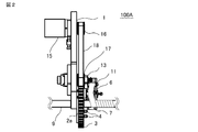
- FIG. 2 is a left side view of FIG.
- FIG. 3 is a perspective view of the taping device according to the first embodiment
- FIG. 4 is a view cut on a horizontal plane with reference to the rotation center of the taping body in the taping device according to the first embodiment. It is a sectional view seen from the side.
- the taping device 100A has a flat plate-shaped base 1 as a substrate, and a hollow disk-shaped lower guide ring 2a is attached to the upper surface of the base 1.
- a semi-circular notch 1h is formed in the base 1, a semi-circular notch 2h forming the lower guide ring 2a in a C shape, and a convex step portion 2s on the upper surface are formed in the lower guide ring 2a. Is formed.
- the lower guide ring 2a is fixed to the base 1 so that the central axis of the lower guide ring 2a and the central axis of the semicircular notch 1h formed in the base 1 coincide with each other.
- a concave step portion 3s is formed on the surface of the timing pulley 3 when viewed from the direction of the rotation axis. Further, the timing pulley 3 is formed with an inner diameter portion having the same shape as the outer shape of the stepped portion 2s of the lower guide ring 2a, and a notch portion 3h is formed. The timing pulley 3 is configured such that the inner diameter portion is held by the stepped portion 2s of the lower guide ring 2a and can freely rotate about the base 1 and the lower guide ring 2a as a rotation axis.
- the hollow disk-shaped upper guide ring 2b has an inner diameter and a notch portion having the same diameter as the lower guide ring 2a, and is engaged with and fixed to the stepped portion 2s of the lower guide ring 2a. It is held so that it does not move in the direction of the rotation axis. That is, the lower guide ring 2a and the upper guide ring 2b constitute the guide ring of the timing pulley 3, and hold the timing pulley 3 rotatably and do not move in the direction of the rotation axis.
- a notch portion is formed in the guide ring composed of the lower guide ring 2a and the upper guide ring 2b, and the notch portion 3h is formed in the timing pulley 3, and the guide ring and the timing are formed. It becomes easy to align the notch position of the pulley 3.
- the cylindrical roller guide 4 is rotatably configured and is arranged at an equal angle on the same circumference with the rotation center of the timing pulley 3 as the center. Further, the roller guide 4 is vertically mounted in the roller guide mounting hole 5 formed on the upper surface of the upper guide ring 2b. A plurality of roller guide mounting holes 5 are formed, and as will be described later, the mounting position of the roller guide 4 can be changed so that the timing at which tension is applied to the tape and the magnitude of tension can be changed.
- the tape bobbin 6 has left and right surfaces sandwiched by disks with respect to the moving direction of the tape 7 wound around the winding core in advance, and is attached to the upper surface of the timing pulley 3 in the vertical direction. Further, as shown in FIG. 4, the tape bobbin 6 is pressed against the timing pulley 3 via the spacer 6c by the spring force of the coil 6b attached to the bobbin rotation shaft 6a, which makes the movement in the rotation direction stiff. It is configured as follows.
- the tape guide 8 is formed in a cylindrical shape and is fixed so as to be inclined outward with respect to the upper surface of the timing pulley 3 as shown in FIG. 4, and is arranged at the center of the rotation axis of the timing pulley 3.
- the tape 7 wound around the taping body 9 is guided.
- the tape 7 sent out from the tape bobbin 6 is guided by the tape guide 8 along the circumference of the timing pulley 3 while being provided with an angle with respect to the taping body 9, and is wound around the taping body 9. It is turned.
- the angle of the tape 7 sent from the tape guide 8 with respect to the taping body 9 is given by the rotation of the timing pulley 3.
- FIG. 5 shows an enlarged view of the tension mechanism 10 that applies tension to the tape 7.
- the tension mechanism 10 is composed of a tension guide 11, a tension link 12, and a torsion spring 13 that serve as a cylindrical guide.
- the tension guide 11 is provided at an intermediate position between the tape bobbin 6 and the tape guide 8 in order to relay the tape 7 sent from the tape bobbin 6 to the tape guide 8, and winds the tape 7 around the taping body 9. It is configured to change the angle.
- the tension link 12 is formed of, for example, a flat plate, is rotatably provided on the upper surface of the timing pulley 3 as described later, and is one of the upper surfaces of the upper guide ring 2b on the timing pulley 3 side.
- a position where the torsion spring 13 comes into contact with the stopper 14 described later due to a force that protrudes into the portion contacts the roller guide 4 due to the rotation of the timing pulley 3, and jumps up, and returns to the direction in which the torsion of the torsion spring 13 is canceled when the torsion spring 13 is separated from the roller guide 4. It is configured to return to.
- the tension guide 11 is attached to the end of the tension link 12 in the vertical direction, and the direction of the force generated when the torsion spring 13 is twisted is counterclockwise around the center of rotation.
- the stopper 14 is vertically attached to the upper surface of the timing pulley 3, and one end of the tension link 12 is pressed against the stopper 14 by the spring force of the torsion spring 13 provided at the center of rotation of the tension link 12 to rotate. Is suppressed. That is, one end of the torsion spring 13 is fixed to the tension link 12, and the other end is fixed to the stopper 14, and the tension link 12 is urged by the torsion spring 13 so as to be tilted counterclockwise in FIG. The position shown in FIG. 5 is maintained by the contact between the tension link 12 and the stopper 14.
- the drive motor 15 is provided in the upper center of the base 1, and the output shaft is attached so as to penetrate from the lower surface to the upper surface of the base 1.
- a drive pulley 16 is fixed to the output shaft of the drive motor 15, and the drive pulley 16 rotates together with the drive motor 15.
- Two sub-pulley 17a and 17b are rotatably provided on the outer circumference of the timing pulley 3.
- the sub pulleys 17a and 17b are fixed to the base 1 at a position far from the width direction of the lower guide ring 2a and the upper guide ring 2b or the step portion 3s of the timing pulley 3 so that the rotation axis is perpendicular to the base 1.
- the sub-pulley 17a is engaged with the stepped portion 3s of the timing pulley 3
- the sub-pulley 17b is engaged with the bobbin rotation shaft 6a.
- the belt 18 is a double-edged timing belt, in which the teeth on the inner surface engage the drive pulley 16 and the two sub pulleys 17a and 17b, and the teeth on the outer surface engage the stepped portion 3s of the timing pulley 3.
- the timing pulley 3 is rotated and the tape 7 is taped by transmitting the rotation of the drive motor 15 from the drive pulley 16 to the timing pulley 3 and the tape bobbin 6 via the sub pulleys 17a and 17b. Wind around the body 9.
- the taping device 100A is configured as described above, and the operation thereof will be described next.
- FIGS. 6A and 6B when the tape 7 is wound around the taping body 9, the timing pulley 3 is rotated clockwise from the position of FIG. 5A due to the rotation of the drive motor 15, that is, FIG. In 6 (a), the tension link 12 rotates clockwise and comes into contact with the roller guide 4. At this time, depending on the rotation angle of the timing pulley 3, the tension link 12 tilts counterclockwise and jumps up as shown by the arrow Y in FIG. 6B while the angle changes clockwise with respect to the center of rotation.
- the tape 7 attached to the tape bobbin 6 is periodically tensioned and wound around the taping body 9 via the tension guide 11 and the tape guide 8.
- the tape length from the tape 7 sent from the tape bobbin 6 to the taping body 9 is always constant. ..
- the tension link 12 jumps up while changing its angle clockwise due to the clockwise rotation of the timing pulley 3, so that the position of the tension guide 11 changes, so that the tape 7 and the cover are sent from the tape bobbin 6.
- the tape length up to the taping body 9 changes.
- the force required for the rotation of the tape bobbin 6 is set to be larger than the force for pulling the tape 7, so that the tension link 12
- the change in the tape length from the tape 7 sent from the tape bobbin 6 to the taping body 9 caused by the change in the position of the tension guide 11 due to the jumping up of the tape is suppressed, and the tape 7 wound around the taping body 9 is suppressed. Tension is generated in the tape length direction.
- the tension guide 11 and the tension guide 11 relay the tape 7 sent from the tape bobbin 6 to the tape guide 8 which is wound around the taping body 9 at an angle along the circumference of the timing pulley 3.
- a tension mechanism 10 including a torsion spring 13 provided at the center of rotation of the tension link 12, and a roller guide 4 fixed to the upper surface of the upper guide ring 2b.
- the mounting position of the roller guide 4 coincides with the extension line of the straight line connecting the vertices of the taping body 9 from the center of the rotation axis of the timing pulley 3 and the roller guide mounting hole 5 arranged on the upper surface of the upper guide ring 2b.
- Tension can be applied at the corners of the taping body 9 by providing the taping body 9 at a position where the taping body 9 is to be taped.
- the timing of applying tension to the tape 7 and the magnitude of the tension can be changed, so that the cross-sectional shape can be changed.
- the roller guide mounting position is aligned with the cross-sectional shape of the taping body 9, so that the tape 7 is fitted to the taping body 9 to suppress wrinkles or sagging of the appearance of the finished product. be able to.
- the taping device 100A can be provided by aligning the notch positions of the guide ring and the timing pulley 3.
- the taping body 9 can be arranged at the center of rotation of the timing pulley 3 without disassembling.
- Embodiment 2 Next, the taping device according to the second embodiment will be described.
- the radius of curvature from the center of rotation of the timing pulley 3, the angular pitch between the roller guides 4, and the mounting position of the roller guide 4 may be changed.
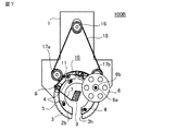
- FIG. 7 is a front view showing the taping device according to the second embodiment.
- the taping device 100B according to the second embodiment is a diagram showing a case where the tape 7 is wound around a taping body 9 having a rhombic cross-sectional shape.
- the roller guide 4 is attached on an extension line connecting the four vertices of the diamond-shaped taping body 9 from the center of rotation of the timing pulley 3.
- Other configurations are the same as those of the taping device 100A described in the first embodiment, and duplicate description will be omitted.
- the taping device 100B even if the taping body 9 has a polygonal cross section, a plurality of roller guide mounting holes 5 arranged on the upper surface of the upper guide ring 2b are provided in advance.
- the tape 7 can be wound around taping bodies having various cross-sectional shapes with the same taping device. Then, by creating a function of applying tension while pulling the tape 7 to the taping body 9, it is possible to eliminate the slack of the tape 7 during taping, and the tape 7 wrinkles with respect to the taping body 9. It can be wound without any gap between the winding surface and the winding surface.
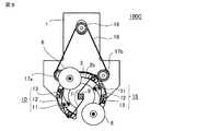
- FIG. 8 is a diagram showing the taping device 100C according to the third embodiment.
- the tension mechanism 10 and the tape 7 wound around the taping body 9 are wound while giving an angle to the taping body 9 in order to perform taping with one tape 7.
- the configuration in which the rotating tape guide 8 is provided has been illustrated and described, as shown in FIG. 8, in order to tape a plurality of tapes 7 at the same time, the number of tapes 7, the tension mechanism 10, and the tape guides 8 are made to correspond to each other. It may be arranged.
- a tape bobbin 6 to which the tape 7 is fixed a tape guide 8 for winding the tape 7 around the taping body 9 at an angle, and a tension mechanism with the rotation center axis of the timing pulley 3 symmetrical.
- Two sets of 10 are arranged respectively. Since the other configurations are the same as those in the first embodiment or the second embodiment, duplicate description will be omitted.
- taping can be performed while two types of tapes 7 are stacked at the same time, and the man-hours for taping can be reduced.
Landscapes
- Braiding, Manufacturing Of Bobbin-Net Or Lace, And Manufacturing Of Nets By Knotting (AREA)
- Basic Packing Technique (AREA)
- Manufacture Of Motors, Generators (AREA)
Priority Applications (3)
| Application Number | Priority Date | Filing Date | Title |
|---|---|---|---|
| JP2022530416A JP7271793B2 (ja) | 2020-06-10 | 2020-06-10 | テーピング装置 |
| PCT/JP2020/022777 WO2021250801A1 (ja) | 2020-06-10 | 2020-06-10 | テーピング装置 |
| CN202080101578.XA CN115916677B (zh) | 2020-06-10 | 2020-06-10 | 编带装置 |
Applications Claiming Priority (1)
| Application Number | Priority Date | Filing Date | Title |
|---|---|---|---|
| PCT/JP2020/022777 WO2021250801A1 (ja) | 2020-06-10 | 2020-06-10 | テーピング装置 |
Publications (1)
| Publication Number | Publication Date |
|---|---|
| WO2021250801A1 true WO2021250801A1 (ja) | 2021-12-16 |
Family
ID=78845531
Family Applications (1)
| Application Number | Title | Priority Date | Filing Date |
|---|---|---|---|
| PCT/JP2020/022777 Ceased WO2021250801A1 (ja) | 2020-06-10 | 2020-06-10 | テーピング装置 |
Country Status (3)
| Country | Link |
|---|---|
| JP (1) | JP7271793B2 (https=) |
| CN (1) | CN115916677B (https=) |
| WO (1) | WO2021250801A1 (https=) |
Citations (4)
| Publication number | Priority date | Publication date | Assignee | Title |
|---|---|---|---|---|
| JPS56108669A (en) * | 1980-01-31 | 1981-08-28 | Mitsubishi Electric Corp | Method of measure shape of object for taping and device therefor, and method to tape and device therefor |
| JPS56165668A (en) * | 1980-05-22 | 1981-12-19 | Mitsubishi Electric Corp | Tape winder |
| JP2001006461A (ja) * | 1999-06-24 | 2001-01-12 | Fujikura Ltd | 自動テープ巻き方法およびその装置 |
| JP2011046461A (ja) * | 2009-08-25 | 2011-03-10 | Toshiba Corp | 張力制御装置、テーピング装置およびステータコイルの製造方法 |
Family Cites Families (7)
| Publication number | Priority date | Publication date | Assignee | Title |
|---|---|---|---|---|
| JPS5847775A (ja) * | 1981-09-10 | 1983-03-19 | Minamisenjiyu Seisakusho:Kk | テ−プ巻付方法 |
| JPS62296749A (ja) * | 1986-06-13 | 1987-12-24 | Toshiba Corp | テ−ピング装置 |
| JPH0977388A (ja) * | 1995-09-14 | 1997-03-25 | Toshiba Corp | テーピング機 |
| JP2006306508A (ja) * | 2005-04-26 | 2006-11-09 | Mitsubishi Electric Corp | テーピング装置 |
| CN102185435B (zh) * | 2011-01-26 | 2012-09-26 | 吴江固德电材系统股份有限公司 | 包带头 |
| JP2017001844A (ja) * | 2015-06-12 | 2017-01-05 | 住友電装株式会社 | テープ巻付装置及びチューブ状外装部材取付装置 |
| CN108809017A (zh) * | 2017-04-26 | 2018-11-13 | 龚建林 | 新型内圈送带包带方法 |
-
2020
- 2020-06-10 WO PCT/JP2020/022777 patent/WO2021250801A1/ja not_active Ceased
- 2020-06-10 JP JP2022530416A patent/JP7271793B2/ja active Active
- 2020-06-10 CN CN202080101578.XA patent/CN115916677B/zh active Active
Patent Citations (4)
| Publication number | Priority date | Publication date | Assignee | Title |
|---|---|---|---|---|
| JPS56108669A (en) * | 1980-01-31 | 1981-08-28 | Mitsubishi Electric Corp | Method of measure shape of object for taping and device therefor, and method to tape and device therefor |
| JPS56165668A (en) * | 1980-05-22 | 1981-12-19 | Mitsubishi Electric Corp | Tape winder |
| JP2001006461A (ja) * | 1999-06-24 | 2001-01-12 | Fujikura Ltd | 自動テープ巻き方法およびその装置 |
| JP2011046461A (ja) * | 2009-08-25 | 2011-03-10 | Toshiba Corp | 張力制御装置、テーピング装置およびステータコイルの製造方法 |
Also Published As
| Publication number | Publication date |
|---|---|
| CN115916677A (zh) | 2023-04-04 |
| CN115916677B (zh) | 2025-08-12 |
| JP7271793B2 (ja) | 2023-05-11 |
| JPWO2021250801A1 (https=) | 2021-12-16 |
Similar Documents
| Publication | Publication Date | Title |
|---|---|---|
| JP5005561B2 (ja) | 塗膜転写具 | |
| JPWO2004021377A1 (ja) | 矩形断面線材の巻線装置 | |
| JP2009166437A6 (ja) | 塗膜転写具 | |
| JP2004328985A (ja) | フラットケーブル巻き取り繰り出し装置 | |
| US20190073853A1 (en) | Paper sheet accommodation apparatus and paper sheet accommodation method | |
| JP6448670B2 (ja) | テンションローラ、張力調整装置及び電動機の製造方法 | |
| WO2021250801A1 (ja) | テーピング装置 | |
| JP6906695B2 (ja) | 張力調整装置、巻線装置および回転電機の製造方法 | |
| JP7566557B2 (ja) | 捲回装置、および捲回体の製造方法 | |
| WO2020065853A1 (ja) | 巻線ノズル、及び巻線機 | |
| JP5233311B2 (ja) | 整列曲げ成形方法、及び整列曲げ成形装置 | |
| JP4899091B2 (ja) | 転写具 | |
| JP6515054B2 (ja) | コイルの巻線装置、コイルの巻線方法及びネガティブベンドコイル | |
| JP6595695B2 (ja) | ステータ及び導線巻回方法 | |
| JP3570946B2 (ja) | 巻線方法と巻線治具および巻線装置 | |
| JP3737792B2 (ja) | 渦巻型コイル製造装置、及び渦巻型コイルの製造方法 | |
| JPH1092680A (ja) | 平角線のエッジワイズ巻線方法および巻線装置 | |
| JP4383804B2 (ja) | コイル絶縁紙成形装置 | |
| JP2008080661A (ja) | 転写具 | |
| JP4867416B2 (ja) | 回転電機用積層コア構造体 | |
| JP7371450B2 (ja) | 巻線形成方法及び巻線形成装置 | |
| JP7765678B1 (ja) | ステータの製造方法及びモータの製造方法 | |
| JP2025038392A (ja) | コイル巻線装置及びコイル巻線方法 | |
| JP2000136056A (ja) | 多連リール及び連続巻出し装置 | |
| JPH11139633A (ja) | 原紙ロール支持装置 |
Legal Events
| Date | Code | Title | Description |
|---|---|---|---|
| 121 | Ep: the epo has been informed by wipo that ep was designated in this application |
Ref document number: 20940430 Country of ref document: EP Kind code of ref document: A1 |
|
| ENP | Entry into the national phase |
Ref document number: 2022530416 Country of ref document: JP Kind code of ref document: A |
|
| NENP | Non-entry into the national phase |
Ref country code: DE |
|
| 122 | Ep: pct application non-entry in european phase |
Ref document number: 20940430 Country of ref document: EP Kind code of ref document: A1 |
|
| WWG | Wipo information: grant in national office |
Ref document number: 202080101578.X Country of ref document: CN |