WO2021246018A1 - ロックノブアタッチメント、ラバトリー用のドア、および、ロックノブアタッチメントの取付方法 - Google Patents
ロックノブアタッチメント、ラバトリー用のドア、および、ロックノブアタッチメントの取付方法 Download PDFInfo
- Publication number
- WO2021246018A1 WO2021246018A1 PCT/JP2021/010333 JP2021010333W WO2021246018A1 WO 2021246018 A1 WO2021246018 A1 WO 2021246018A1 JP 2021010333 W JP2021010333 W JP 2021010333W WO 2021246018 A1 WO2021246018 A1 WO 2021246018A1
- Authority
- WO
- WIPO (PCT)
- Prior art keywords
- door
- mounting
- lock knob
- lock
- knob attachment
- Prior art date
- Legal status (The legal status is an assumption and is not a legal conclusion. Google has not performed a legal analysis and makes no representation as to the accuracy of the status listed.)
- Ceased
Links
Images







Classifications
-
- E—FIXED CONSTRUCTIONS
- E05—LOCKS; KEYS; WINDOW OR DOOR FITTINGS; SAFES
- E05B—LOCKS; ACCESSORIES THEREFOR; HANDCUFFS
- E05B1/00—Knobs or handles for wings; Knobs, handles, or press buttons for locks or latches on wings
- E05B1/0053—Handles or handle attachments facilitating operation, e.g. by children or burdened persons
-
- B—PERFORMING OPERATIONS; TRANSPORTING
- B64—AIRCRAFT; AVIATION; COSMONAUTICS
- B64C—AEROPLANES; HELICOPTERS
- B64C1/00—Fuselages; Constructional features common to fuselages, wings, stabilising surfaces or the like
- B64C1/14—Windows; Doors; Hatch covers or access panels; Surrounding frame structures; Canopies; Windscreens accessories therefor, e.g. pressure sensors, water deflectors, hinges, seals, handles, latches, windscreen wipers
- B64C1/1407—Doors; surrounding frames
-
- B—PERFORMING OPERATIONS; TRANSPORTING
- B64—AIRCRAFT; AVIATION; COSMONAUTICS
- B64D—EQUIPMENT FOR FITTING IN OR TO AIRCRAFT; FLIGHT SUITS; PARACHUTES; ARRANGEMENT OR MOUNTING OF POWER PLANTS OR PROPULSION TRANSMISSIONS IN AIRCRAFT
- B64D11/00—Passenger or crew accommodation; Flight-deck installations not otherwise provided for
- B64D11/02—Toilet fittings
-
- E—FIXED CONSTRUCTIONS
- E05—LOCKS; KEYS; WINDOW OR DOOR FITTINGS; SAFES
- E05B—LOCKS; ACCESSORIES THEREFOR; HANDCUFFS
- E05B1/00—Knobs or handles for wings; Knobs, handles, or press buttons for locks or latches on wings
- E05B1/0015—Knobs or handles which do not operate the bolt or lock, e.g. non-movable; Mounting thereof
-
- E—FIXED CONSTRUCTIONS
- E05—LOCKS; KEYS; WINDOW OR DOOR FITTINGS; SAFES
- E05B—LOCKS; ACCESSORIES THEREFOR; HANDCUFFS
- E05B1/00—Knobs or handles for wings; Knobs, handles, or press buttons for locks or latches on wings
- E05B1/0069—Sanitary doorknobs or handles, e.g. comprising a disinfectant
-
- E—FIXED CONSTRUCTIONS
- E05—LOCKS; KEYS; WINDOW OR DOOR FITTINGS; SAFES
- E05B—LOCKS; ACCESSORIES THEREFOR; HANDCUFFS
- E05B3/00—Fastening knobs or handles to lock or latch parts
-
- E—FIXED CONSTRUCTIONS
- E05—LOCKS; KEYS; WINDOW OR DOOR FITTINGS; SAFES
- E05B—LOCKS; ACCESSORIES THEREFOR; HANDCUFFS
- E05B65/00—Locks or fastenings for special use
- E05B65/0035—Locks or fastenings for special use for privacy rooms, e.g. bathrooms
-
- E—FIXED CONSTRUCTIONS
- E05—LOCKS; KEYS; WINDOW OR DOOR FITTINGS; SAFES
- E05B—LOCKS; ACCESSORIES THEREFOR; HANDCUFFS
- E05B65/00—Locks or fastenings for special use
- E05B65/0085—Locks or fastenings for special use for folding wings, e.g. bi-fold wings
-
- E—FIXED CONSTRUCTIONS
- E05—LOCKS; KEYS; WINDOW OR DOOR FITTINGS; SAFES
- E05C—BOLTS OR FASTENING DEVICES FOR WINGS, SPECIALLY FOR DOORS OR WINDOWS
- E05C1/00—Fastening devices with bolts moving rectilinearly
- E05C1/004—Fastening devices with bolts moving rectilinearly parallel to the surface on which the fastener is mounted
-
- E—FIXED CONSTRUCTIONS
- E05—LOCKS; KEYS; WINDOW OR DOOR FITTINGS; SAFES
- E05C—BOLTS OR FASTENING DEVICES FOR WINGS, SPECIALLY FOR DOORS OR WINDOWS
- E05C1/00—Fastening devices with bolts moving rectilinearly
- E05C1/02—Fastening devices with bolts moving rectilinearly without latching action
- E05C1/04—Fastening devices with bolts moving rectilinearly without latching action with operating handle or equivalent member rigid with the bolt
-
- E—FIXED CONSTRUCTIONS
- E05—LOCKS; KEYS; WINDOW OR DOOR FITTINGS; SAFES
- E05B—LOCKS; ACCESSORIES THEREFOR; HANDCUFFS
- E05B17/00—Accessories in connection with locks
- E05B17/0054—Fraction or shear lines; Slip-clutches, resilient parts or the like for preventing damage when forced or slammed
- E05B17/0062—Fraction or shear lines; Slip-clutches, resilient parts or the like for preventing damage when forced or slammed with destructive disengagement
-
- E—FIXED CONSTRUCTIONS
- E06—DOORS, WINDOWS, SHUTTERS, OR ROLLER BLINDS IN GENERAL; LADDERS
- E06B—FIXED OR MOVABLE CLOSURES FOR OPENINGS IN BUILDINGS, VEHICLES, FENCES OR LIKE ENCLOSURES IN GENERAL, e.g. DOORS, WINDOWS, BLINDS, GATES
- E06B3/00—Window sashes, door leaves, or like elements for closing wall or like openings; Layout of fixed or moving closures, e.g. windows in wall or like openings; Features of rigidly-mounted outer frames relating to the mounting of wing frames
- E06B3/32—Arrangements of wings characterised by the manner of movement; Arrangements of movable wings in openings; Features of wings or frames relating solely to the manner of movement of the wing
- E06B3/48—Wings connected at their edges, e.g. foldable wings
Definitions
- the present invention relates to a lock knob attachment, a door for a lavatory, and a method for attaching the lock knob attachment.
- Infectious diseases such as coronavirus are often used by an unspecified number of people and spread through door handles and handrails.
- a non-infected person touches a door handle or the like operated by the infected person by directly touching it with his / her hand or finger
- the virus adheres to the hand or finger of the non-infected person.
- this non-infected person touches his / her mouth, nose, eyes, etc. with the virus-attached hand or finger
- the virus may invade the body and the non-infected person may be infected with an infectious disease. be. Therefore, in order to prevent infectious diseases, it is effective to reduce the number of places that an unspecified number of people directly touch with their hands or fingers.
- Patent Document 1 there is a technique shown in Patent Document 1 as a facility that can be used by a user without touching a door or the like for entering and exiting a toilet or the like.
- an airtight room having an entrance / exit, a toilet booth installed in the airtight room, a door for opening / closing the entrance / exit, and a door by stepping on a mat sensor installed on the floor surface of the entrance / exit of the entrance / exit”.
- An air curtain generator that operates in conjunction with the door opening by the door opening / closing device to open the door, and an air curtain generator that creates an air curtain by the airflow from the top of the doorway downward, and plasma generation that mixes plasma into the airflow.
- the device and the toilet unit provided with the device are disclosed.
- an object of the present invention is to provide a technique that enables a user to lock and unlock a door without using a finger or a hand.
- the lock knob attachment in some embodiments is connected to a mounting portion that can be mounted on a lock bar that locks the door by sliding in a first direction, and the mounting portion is connected to the mounting portion.
- a main body portion extending from the portion in a second direction perpendicular to the first direction is provided.
- the direction perpendicular to both the first direction and the second direction is defined as the third direction
- the length of the main body portion in the direction along the third direction is the mounting in the direction along the third direction. Larger than the length of the part.
- the door for the lavatory in some embodiments includes the above-mentioned lock knob attachment, a door panel rotatably attached to the first wall of the lavatory around the door hinge axis, and a handle portion arranged on the door panel.
- the lock bar is provided.
- the door panel has a long hole portion in which the mounting portion can be slidably moved.
- the method of attaching the lock knob attachment in some embodiments is a method of attaching the lock knob attachment to the door for the lavatory.
- the door is rotatably attached to the first wall of the lavatory around a door hinge axis and is engageable with a door panel having a long hole, a base arranged inside the door panel, and a second wall of the lavatory.
- a lock bar that has an engaging portion and can be repositioned from the unlocked position retracted from the second wall to the locked position engaged with the second wall by sliding in the first direction. Be prepared.
- the lock knob attachment has a mounting portion that can be attached to the lock bar and can be slidably moved along the elongated hole portion, and a second direction that is connected to the mounting portion and is perpendicular to the first direction from the mounting portion. It is equipped with a main body that extends to.
- the direction perpendicular to both the first direction and the second direction is defined as the third direction
- the length of the main body portion in the direction along the third direction is the mounting in the direction along the third direction. Larger than the length of the part.
- the mounting method includes a step of inserting the mounting portion into the elongated hole portion by moving the mounting portion in a direction toward the lock bar, and the mounting portion of the mounting portion via a fastening member. It is provided with a step of fixing to.
- FIG. 1 is a diagram showing a conventional bifold door.
- FIG. 2 is a schematic view of the handle attachment according to the first embodiment.
- FIG. 3 is a perspective view of the lock knob attachment according to the first embodiment.
- FIG. 4 is a side view of the lock knob attachment.
- FIG. 5 is a diagram illustrating an operation using the lock knob attachment.
- FIG. 6 is a front view of the lock knob attachment.
- FIG. 7 is a front view and a side view of a modified example of the lock knob attachment.
- FIG. 8 is a schematic front view schematically showing a door for a lavatory according to a second embodiment.
- FIG. 9 is a schematic perspective view schematically showing an example of a handle attachment.
- FIG. 1 is a diagram showing a conventional bifold door.
- FIG. 2 is a schematic view of the handle attachment according to the first embodiment.
- FIG. 3 is a perspective view of the lock knob attachment according to the first embodiment.
- FIG. 4 is a side view of
- FIG. 10 is a schematic perspective view schematically showing a state after the lock knob attachment is fixed to the lock bar.
- FIG. 11 is a schematic three-view view schematically showing the lock knob attachment according to the second embodiment.
- FIG. 12 is a diagram schematically showing a state before the lock knob attachment is fixed to the lock bar.
- FIG. 13 is an enlarged view showing a part of the lock knob attachment fixed to the lock bar.
- FIG. 14 is a diagram schematically showing a state in which the mounting portion of the lock knob attachment is broken at the weakened portion.
- FIG. 15 is a diagram schematically showing a state in which one step of the method of attaching the lock knob attachment is being executed.
- FIG. 16 is a diagram schematically showing a state in which one step of the method of attaching the lock knob attachment is being executed.
- FIG. 17 is a diagram schematically showing a state in which one step of the method of attaching the lock knob attachment is being executed.
- FIG. 18 is a diagram schematically showing a state in which
- the "handle” is a member that applies a force with a hand or a finger to open and close the door, and is a member that can be provided in a space in which a part of the door is depressed or protruding from the door.
- the "door hinge” means a member for rotatably attaching to the wall surface of the opening in which the door is installed.
- the "door hinge shaft” means a rotation shaft of a door attached by a door hinge. The door hinge axis is substantially parallel in the vertical direction if the rotation axis of the door is vertical, but the door hinge axis may be substantially parallel in the horizontal direction if the door is movable in the vertical direction.
- the "door” of the present disclosure includes a door composed of a panel including one flat surface or a curved surface, a bifold door having a structure that folds in the middle along a second door hinge axis, and a bellows-shaped expandable panel. It means the one including the door having.
- the "lock knob” is a protruding member (for example, a rod-shaped member) protruding from the door toward the room in order to lock or unlock the door, and the locking position and unlocking are performed by moving the protruding member. It means a member whose position can be switched.
- the direction in which the lock bar moves from the unlocked position to the locked position is defined as the first direction DR1.
- the direction perpendicular to the first direction DR1 is defined as the second direction DR2.
- the second direction DR2 is a direction toward the main body portion of the lock knob attachment from the mounting portion of the lock knob attachment.
- the second direction DR2 is the direction perpendicular to the main surface of the door panel 10.
- the direction perpendicular to both the first direction DR1 and the second direction DR2 is defined as the third direction DR3.
- the third direction DR3 is the direction parallel to the door hinge axis.
- FIG. 1 is an example of a bifold door 1 having a center-folding structure, which is used in a restroom of an aircraft, as viewed from the inside of the restroom.
- the bifold door 1 is rotatably attached to a wall (not shown) in the aircraft by a door hinge shaft 2 so that it can be folded by a center-folded portion 4 (in other words, a second door hinge shaft). It is designed.
- a center-folded portion 4 in other words, a second door hinge shaft
- the user needs to operate the handle portion 3 and the lock knob 5 by using a finger or a hand when entering or leaving the room.
- the restroom for aircraft has a hand-washing area in the restroom, it is necessary for the user to touch the handle 3 and the lock knob 5 after washing their hands. It is required that the door can be opened and closed without using hands.
- FIG. 2 is a schematic view of the handle attachment.
- the handle attachment 20 includes a base portion 21 and a flap portion 25.
- the handle attachment 20 may include an auxiliary base portion 26 that can be coupled to the base portion 21 in order to sandwich the door between the base portion 21 and the auxiliary base portion 26.
- the base portion 21 is fixed to the wall surface of the door by using a fixing member such as a screw.
- the flap portion 25 is rotatably attached to the base portion 21 via a flap rotation mechanism 24 such as a pin member.
- the flap rotation mechanism 24 is provided on the door wall surface side 22 of the flap portion 25. Further, the flap portion 25 has a horizontally long surface in a direction substantially perpendicular to the door hinge axis on the side 23 opposite to the door wall surface side. Further, the flap portion 25 is urged against the base portion 21 by using a member such as a spring so that the tip portion 27 on the side far from the flap rotation mechanism 24 is directed toward the direction away from the wall surface of the door. ..
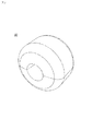
- FIG. 3 is a perspective view of the lock knob attachment 60
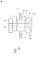
- FIG. 4 is a side view of the lock knob attachment 60.
- the lock knob attachment 60 is an attachment that can be attached to the lock knob 5.
- the lock knob attachment 60 has an outer diameter larger than that of a mounting portion 61 having a cavity that can be fitted to the lock knob 5 and a mounting portion that protrudes from the mounting portion 61 in the normal direction of the door surface. (See FIG. 4).
- FIG. 5 shows a state in which the bifold door 1 to which the handle attachment 20 and the lock knob attachment 60 are attached is closed.
- the diameter of the main body portion 62 is larger than that of the mounting portion 61 so that the door of the restroom can be easily locked by the arm / elbow or the like. Further, the tip of the main body 62 has a small diameter and a trapezoidal cross section so as not to be mistaken for a door handle.
- the shape of the lock knob attachment 60 is not necessarily limited to these shapes.
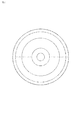
- FIG. 6 is a front view of the lock knob attachment 60.
- the front shape of the lock knob attachment 60 described above is circular, the front shape is not limited to a circle.
- the front shape is a vertically long shape (more specifically, an oval shape or an elliptical shape), and the arms and elbows are. The shape may be such that a force is easily applied when the arm is moved in the horizontal direction.
- the lock knob attachment described above is not limited to the door that opens and closes in the horizontal direction, but also the door of the baggage storage space of the aircraft that opens and closes in the vertical direction. May be applied.
- the lock knob attachment can be applied to various places such as a locked part of a door in equipment such as a galley.
- FIG. 8 is a schematic front view schematically showing the door 1 for the lavatory in the second embodiment.
- FIG. 9 is a schematic perspective view schematically showing an example of the handle attachment 20.
- FIG. 10 is a schematic perspective view schematically showing a state after the lock knob attachment 60 is fixed to the lock bar 70.
- FIG. 11 is a schematic three-view view schematically showing the lock knob attachment 60 according to the second embodiment. A schematic plan view is described on the upper side of FIG. 11, a schematic front view is described on the lower right side of FIG. 11, and a schematic side view is described on the lower left side of FIG. 11.
- FIG. 12 is a diagram schematically showing a state before the lock knob attachment 60 is fixed to the lock bar 70.
- FIG. 13 is an enlarged view showing a part of the lock knob attachment 60 fixed to the lock bar 70.
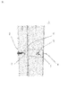
- FIG. 14 is a diagram schematically showing a state in which the mounting portion 61 of the lock knob attachment 60 is broken at the weakened portion 614.
- 15 to 18 are diagrams schematically showing a state in which one step of the mounting method of the lock knob attachment 60 is being executed.
- the lavatory door 1 is attached to a wall 101 (more specifically, the wall of an aircraft lavatory unit).
- the door 1 opens and closes the opening OP defined by the wall 101.
- the door 1 includes a door panel 10, a handle portion 3, a lock bar 70, and a lock knob attachment 60.
- the door panel 10 is rotatably attached to the first wall 101a of the lavatory 100 around the door hinge shaft AX1.
- the door panel 10 may be composed of one panel, or may be composed of a plurality of panels including the first panel 11 and the second panel 12.
- the first panel 11 and the second panel 12 are rotatably connected around the second door hinge shaft AX2.
- the door 1 in FIG. 8 is a bifold door.
- the door panel 10 (more specifically, the first panel 11) has a long hole portion 13h in which the attachment portion 61 of the lock knob attachment 60 can be slidably moved.
- the main body 62 of the lock knob attachment 60 is arranged on the front side of the long hole portion 13h, and the lock bar 70 is arranged on the back side of the long hole portion 13h.
- the door panel 10 (more specifically, the first panel 11) has a second elongated hole portion 15h parallel to the elongated hole portion 13h.
- a lock state display unit 7 is arranged behind the second long hole portion 15h. The lock state display unit 7 selectively displays a first display indicating that the door 1 is in the locked state and a second display indicating that the door 1 is in the unlocked state on the outer surface of the restroom. ..
- the handle portion 3 is a portion operated by the user when the door 1 is opened.
- the handle portion 3 is arranged on the door panel 10 (more specifically, the second panel 12).
- the handle portion 3 may include the handle attachment according to the first embodiment, or may include a handle attachment different from the handle attachment according to the first embodiment.
- the handle portion 3 may be a known handle portion as illustrated in FIG.
- the handle attachment 20 includes a base portion 21, a flap portion 25, a flap rotation mechanism 24 (more specifically, a pin member 50), and an urging member 29.
- the base portion 21 is attached to a part of the wall surface 1s of the door 1. In the example shown in FIG. 8, the base portion 21 is attached to the door panel 10.
- the flap portion 25 is pulled by the user to apply a pulling force to the door 1 (more specifically, the door panel 10) via the base portion 21.
- the state of the door 1 is switched from the closed state in which the opening OP of the wall 101 is closed to the open state in which the opening OP is opened.
- the flap unit 25 functions as a first operation unit operated by the user.
- the flap portion 25 is arranged at a position away from the base end portion 28 connected to the flap rotation mechanism 24 (more specifically, the pin member 50) and the flap rotation mechanism 24. It has a tip portion 27 to be formed. It is preferable that the flap portion 25 has a horizontally long shape in which the length in the direction perpendicular to the rotation axis AX of the flap portion 25 is longer than the length in the direction parallel to the rotation axis AX of the flap portion 25.
- the urging member 29 urges the flap portion 25 with respect to the base portion 21 in the first rotation direction R1 around the rotation shaft AX.
- the first rotation direction R1 is a direction in which the tip end portion 27 of the flap portion 25 is separated from the wall surface of the door 1.
- the urging member 29 is a torsion coil spring 29s.
- the pin member 50 is inserted into the coil portion of the torsion coil spring 29s.
- one end of the torsion coil spring 29s is in contact with the base portion 21, and the other end of the torsion coil spring 29s is in contact with the flap portion 25. From the viewpoint of safety, it is preferable that one end and / or the other end of the torsion coil spring 29s is accommodated in a groove or a hole.
- the tip portion 27 of the flap portion 25 is urged in a direction away from the wall surface of the door 1.
- the second effect that the tip portion 27 retracts to the wall surface side of the door 1 when the portion or the wall of the lavatory hits is synergistically produced.
- the first effect makes it possible to smoothly open the door 1 without touching the flap portion 25 with a finger or a hand.
- the second effect prevents the user from being injured and suppresses damage to the wall and the like.
- the flap portion 25 may have a through hole portion 25h on which a finger can be hooked.
- a finger is placed on the through hole portion 25h of the flap portion 25 to form the flap portion 25. It becomes possible to operate. Therefore, it is possible to meet both the request of the user who wants to operate the flap portion 25 using the arm or the elbow and the request of the user who wants to operate the flap portion 25 using the finger.
- the lock bar 70 locks the door by sliding in the first direction DR1. More specifically, the lock bar 70 can be repositioned from the unlocked position retracted from the second wall 101b of the lavatory to the lock position engaged with the second wall 101b by sliding in the first direction DR1. be.
- the second wall 101b is a wall arranged on the side opposite to the first wall 101a with respect to the door 1.
- the lock bar 70 has a base 81 and an engaging portion 82.
- the base 81 is arranged inside the door panel 10.
- the attachment portion 61 of the lock knob attachment 60 is attached to the base portion 81.
- the engaging portion 82 can be engaged with the second wall 101b.
- the engaging portion 82 projects from the inside of the door panel 10 toward the second wall 101b.
- the engaging portion 82 retracts inside the door panel 10.
- the lock bar 70 has a main surface 70m, an upper surface 70u, and a lower surface 70b.
- the main surface 70m is a surface facing the elongated hole portion 13h or a surface facing the second direction DR2 side.
- the lock knob attachment 60 is attached to the lock bar 70.
- the lock knob attachment 60 may be the lock knob attachment according to the first embodiment, or may be the lock knob attachment described later.
- the lock knob attachment 60 includes a mounting portion 61 and a main body portion 62.
- the mounting portion 61 can be mounted on the lock bar 70 that locks the door 1 (more specifically, the door for the aircraft lavatory) by sliding in the first direction DR1.
- the mounting portion 61 is preferably removable from the lock bar 70 without damaging the lock knob attachment 60 and the lock bar 70.
- the mounting portion 61 is made of, for example, metal or resin.
- the main body portion 62 is connected to the mounting portion 61.
- the main body portion 62 extends from the mounting portion 61 in the second direction DR2 (the direction perpendicular to the first direction DR1).
- the length L1 of the main body portion 62 in the direction parallel to the third direction DR3 is larger than the length L2 of the mounting portion 61 in the direction parallel to the third direction DR3. Since the length L1 is larger than the length L2, the user can easily lock and unlock the door 1 without using a finger or a hand.
- the length L1 of the main body portion 62 in the direction along the third direction DR3 is preferably, for example, 3 cm or more, 4 cm or more, or 5 cm or more.
- the length L3 of the main body portion 62 in the direction parallel to the second direction DR2 is preferably, for example, 2 cm or more, 3 cm or more, or 4 cm or more.
- the length L1 is 3 cm or more and the length L3 is 2 cm or more, the user can more easily lock and unlock the door 1 without using a finger or a hand.
- the area of the main body 62 when viewed in the direction along the first direction DR1 (the area of the shadow formed when the main body 62 is irradiated with parallel light parallel to the first direction DR1) is 6 cm 2 or more and 10 cm 2. The above, or preferably 15 cm 2 or more.
- the main body portion 62 has a substantially semicircular shape when viewed in the direction along the first direction DR1. Further, the main body portion 62 has a substantially oval shape when viewed in a direction along the opposite direction DR4 of the second direction DR2. In this case, (1) the corners of the main body 62 can be eliminated or the number of corners of the main body 62 can be reduced, and (2) the apparent size of the main body 62 (DR4 in the opposite direction of the second direction DR2).
- the size of the main body 62 when viewed in the direction along the first direction) can be reduced, and (3) the area of the part operated by the arm or elbow (the main body 62 when viewed in the direction along the first direction DR1). (Area) can be increased, and (4) the user can intuitively recognize that the main body portion 62 is operated in the direction along the first direction DR1.
- the shape of the main body 62 is not limited to the shape shown in FIG. 11, and is arbitrary.
- the shape of the main body portion 62 may be a substantially cylindrical shape or a substantially prismatic shape.
- the main body portion 62 has a main surface 620, and the central portion of the main surface 620 is a flat surface 620f perpendicular to the first direction DR1.
- the main surface 620 of the main body 62 includes the flat surface 620f, the load acting on the arm or elbow can be dispersed when the main body 62 is operated by using the arm or elbow.
- the main body 62 is made of metal such as aluminum. Alternatively, the main body 62 may be made of resin.
- the main body portion 62 has a first through-hole portion 62h
- the mounting portion 61 has a second through-hole portion 61h. It is preferable that the first through-hole portion 62h and the second through-hole portion 61h each extend in a direction parallel to the second direction DR2.
- the first through hole portion 62h is arranged in the center of the main body portion 62 when viewed in the direction along the opposite direction DR4 of the second direction DR2.
- the opening OP1 on the second direction DR2 side of the first through hole portion 62h is open. Alternatively, the opening OP1 may be closed by a lid or cover.
- the lock knob attachment 60 includes a fastening member 65 for fixing the mounting portion 61 to the lock bar 70.
- the fastening member 65 is inserted into both the first through hole portion 62h and the second through hole portion 61h.
- the fastening member 65 approaches the lock bar 70 via the both through hole portions (62h, 61h). Can be made to. Therefore, the work of attaching the lock knob attachment 60 to the lock bar 70 becomes easy by using the fastening member 65.
- the fastening member 65 is a screw member.
- the fastening member 65 has a head portion 65a and a shaft portion 65b having a male screw 650.
- the lock bar 70 has a female screw 750 to be screwed with the male screw 650 of the fastening member 65.
- the mounting portion 61 has a seating surface 61s that abuts on the head portion 65a of the fastening member 65.
- the seat surface 61s may be provided on the main body portion 62.
- the mounting portion 61 has a detent portion 612s.
- the detent portion 612s prevents the mounting portion 61 and the main body portion 62 from rotating around the longitudinal axis AX3 of the fastening member 65. By preventing the rotation of the main body 62, the user can stably operate the main body 62. Further, by preventing the relative rotational movement between the mounting portion 61 (or the seat surface 61s) and the fastening member 65, loosening of the fastening member 65 is prevented or suppressed.
- the detent portion 612s comes into contact with a surface perpendicular to the main surface 70m of the lock bar 70.
- the detent portion 612s is in contact with the upper surface 70u of the lock bar 70, but the detent portion 612s may be in contact with the lower surface 70b of the lock bar 70.
- the detent portion 612s comes into contact with the upper surface 70u or the lower surface 70b of the lock bar, the rotational movement of the mounting portion 61 is effectively prevented.
- the detent portion 612s can be used as a positioning portion for the lock bar 70.
- the mounting portion 61 does not fall off from the lock bar 70 when the mounting portion 61 is attached to the lock bar 70.
- the mounting portion 61 contacts the first portion 611 that contacts the main surface 70 m of the lock bar 70 and the second surface (70u) that contacts the second surface (70u) perpendicular to the main surface 70 m of the lock bar 70. It has a portion 612 and. Further, the second portion 612 includes the above-mentioned detent portion 612s. In this case, the mounting portion 61 is effectively positioned by the main surface 70m and the second surface (70u) of the lock bar 70. Further, the detented portion 612s stably maintains the positioned state. In the example shown in FIG. 13, the contact portion between the lock bar 70 and the mounting portion 61 is formed in a direction along the longitudinal direction of the lock bar 70 (in other words, a direction along the first direction DR1). It has a substantially L-shape.
- the first portion 611 is provided with a hole into which the fastening member 65 is inserted. Therefore, the contact surface between the first portion 611 and the main surface 70 m is an annular contact surface.
- the mounting portion 61 has a weakening portion 614 that defines the breaking position of the mounting portion 61. Further, the weakened portion 614 is arranged on the DR2 side in the second direction with respect to the elongated hole portion 13h of the door panel 10.
- the weakened portion 614 is, for example, a recess (more specifically, an annular recess) provided on the outer peripheral surface of the mounting portion 61.
- the mounting portion 61 is more likely to break at the weakened portion 614.
- the second through-hole portion 61h includes a portion 610h having an inner diameter larger than the maximum outer diameter of the head portion 65a of the fastening member 65.
- the plane PL that passes through the weakened portion 614 and is perpendicular to the second direction DR2 preferably crosses the portion 610h. In this case, the mounting portion 61 is more likely to break at the weakened portion 614.
- the mounting portion 61 breaks in the weakened portion 614.
- the weakened portion 614 is located on the DR2 side in the second direction with respect to the elongated hole portion 13h of the door panel 10. Therefore, after the mounting portion 61 is broken, the user can operate the lock bar 70 by grasping the portion P between the elongated hole portion 13h and the weakening portion 614 of the mounting portion 61. Therefore, the user is not trapped in the restroom (more specifically, the lavatory of the aircraft).
- the weakened portion 614 is located on the DR2 side in the second direction with respect to the seat surface 61s. Further, the weakening portion 614 is arranged on the second direction DR2 side of the fastening member 65 for fixing the mounting portion 61 to the lock bar 70 on the second direction DR2 side (the position of the weakening portion 614 in FIG. 14). Refer to the positional relationship between the arrow E indicating the position of the fastening member 65 and the arrow F indicating the position of the end of the fastening member 65 on the DR2 side in the second direction.) In this case, the breaking of the mounting portion 61 at the weakened portion 614 is not hindered by the fastening member 65.
- the mounting portion 61 includes a shaft portion 613.
- the shaft portion 613 extends along the second direction DR2.
- the shaft portion 613 is arranged so as to cross the elongated hole portion 13h.
- the shaft portion 613 has a second through hole portion 61h extending along the longitudinal direction of the shaft portion 613.
- the fastening member 65 is inserted into the second through hole portion 61h.
- the shaft portion 613 has a seat surface 61s that abuts on the head portion 65a of the fastening member 65.
- the shaft portion 613 has a small diameter portion 613t and a large diameter portion 613w having a larger outer diameter than the small diameter portion 613t. Further, the large diameter portion 613w is arranged on the second direction DR2 side with respect to the small diameter portion 613t.
- the seat surface 61s is provided inside the large diameter portion 613w.
- the weakening portion 614 is provided on the outer surface of the large diameter portion 613w.
- the shaft portion 613 has a first end portion 613a and a second end portion 613b.
- the first end portion 613a is provided with the above-mentioned first portion 611 that contacts the main surface 70 m of the lock bar 70.
- the second end portion 613b is connected to the main body portion 62.
- the weakened portion 614 is provided at the second end portion 613b.
- the method of attaching the lock knob attachment 60 in the embodiment is a method of attaching the lock knob attachment 60 to the door 1 for the lavatory (more specifically, the door for the aircraft lavatory).
- the door 1 for the lavatory is (1) a door panel 10 rotatably attached to the first wall 101a of the lavatory 100 around the door hinge shaft AX1 and having a long hole portion 13h. (2) It has a base 81 arranged inside the door panel 10 and an engaging portion 82 that can be engaged with the second wall 101b of the lavatory 100, and by sliding in the first direction DR1, the second wall 101b A lock bar 70 that can be repositioned from the unlocked position retracted from the lock position to a lock position that engages with the second wall 101b is provided.
- the lock knob attachment 60 is attached to (1) a mounting portion 61 that can be mounted on the lock bar 70 and that can be slidably moved along the elongated hole portion 13h, and (2) the mounting portion 61. It includes a main body portion 62 that is connected and extends from the mounting portion 61 to the second direction DR2 perpendicular to the first direction DR1. (3) When the direction perpendicular to both the first direction DR1 and the second direction DR2 is defined as the third direction DR3, the length of the main body portion 62 in the direction along the third direction DR3 is along the third direction DR3. It is larger than the length of the mounting portion 61 in the direction.
- the mounting portion 61 of the lock knob attachment 60 is inserted into the elongated hole portion 13h of the door panel 10.
- the first step ST1 is an insertion step. As shown by the arrow in FIG. 15, in the insertion step (first step ST1), the mounting portion 61 is inserted into the elongated hole portion 13h by moving the mounting portion 61 in the direction toward the lock bar 70.
- the insertion step in the insertion step (first step ST1), at least a part 61p of the mounting portion 61 is arranged at a position hidden by the door panel 10 when viewed from the second direction DR2 and the opposite direction DR4. (Note that in FIG. 16, since the partial 61p is located above the upper end of the long hole portion 13h indicated by the alternate long and short dash line, it is clear that the partial 61p is in a position hidden by the door panel 10. It is.).
- the insertion step is to move the mounting portion 61 diagonally upward or after moving the mounting portion 61 in the horizontal direction, and then the mounting portion 61. Is preferably included.
- the insertion step involves bringing the first portion 611 of the mounting portion 61 into contact with the main surface 70 m of the lock bar 70.
- the insertion step may include bringing the second portion 612 (more specifically, the detent portion 612s) of the mounting portion 61 into contact with the second surface (70u) perpendicular to the main surface 70m of the lock bar 70. good.
- the mounting portion 61 is fixed to the lock bar 70 via the fastening member 65.
- the fastening member 65 is moved to the DR4 in the direction opposite to the second direction DR2, so that the fastening member 65 is first penetrated through the main body portion 62. It includes inserting into the hole portion 62h, the second through hole portion 61h of the mounting portion 61, and the hole portion 70h of the lock bar 70.
- a female screw 750 is formed in the hole 70h of the lock bar 70.
- the fixing step includes screwing the male screw 650 of the fastening member 65 into the female screw 750 of the lock bar 70.
- the lock knob attachment 60 is attached to the lock bar 70 (see FIG. 18).
- the lock knob attachment 60 can be attached to the base 81 of the lock bar 70 arranged inside the door panel 10. Therefore, the work of attaching the lock knob attachment 60 to the lock bar 70 can be easily executed. Further, the lock knob attachment replacement work (in other words, the work of removing the lock knob attachment from the lock bar 70 and attaching a new lock knob attachment 60 to the lock bar 70) can be easily performed. For example, if the lock knob attachment 60 is damaged or deteriorated, the damaged or deteriorated lock knob attachment 60 can be removed from the lock bar 70, and a new lock knob attachment 60 can be attached to the lock bar 70.
Landscapes
- Engineering & Computer Science (AREA)
- Mechanical Engineering (AREA)
- Aviation & Aerospace Engineering (AREA)
- Health & Medical Sciences (AREA)
- Epidemiology (AREA)
- Public Health (AREA)
- Extensible Doors And Revolving Doors (AREA)
- Wing Frames And Configurations (AREA)
- Lock And Its Accessories (AREA)
Priority Applications (3)
| Application Number | Priority Date | Filing Date | Title |
|---|---|---|---|
| US17/767,900 US12134914B2 (en) | 2020-06-01 | 2021-03-15 | Lock knob attachment, lavatory door, and method for mounting lock knob attachment |
| JP2022528445A JP7302100B2 (ja) | 2020-06-01 | 2021-03-15 | ロックノブアタッチメント、ラバトリー用のドア、および、ロックノブアタッチメントの取付方法 |
| EP21817171.8A EP4036354A4 (en) | 2020-06-01 | 2021-03-15 | LOCK KNOB MOUNT, TOILET DOOR AND METHOD FOR INSTALLING LOCK KNOB MOUNT |
Applications Claiming Priority (2)
| Application Number | Priority Date | Filing Date | Title |
|---|---|---|---|
| JP2020095239 | 2020-06-01 | ||
| JP2020-095239 | 2020-06-01 |
Publications (1)
| Publication Number | Publication Date |
|---|---|
| WO2021246018A1 true WO2021246018A1 (ja) | 2021-12-09 |
Family
ID=78830827
Family Applications (2)
| Application Number | Title | Priority Date | Filing Date |
|---|---|---|---|
| PCT/JP2021/010333 Ceased WO2021246018A1 (ja) | 2020-06-01 | 2021-03-15 | ロックノブアタッチメント、ラバトリー用のドア、および、ロックノブアタッチメントの取付方法 |
| PCT/JP2021/010331 Ceased WO2021246017A1 (ja) | 2020-06-01 | 2021-03-15 | ハンドルアタッチメント、および、ラバトリー用のドア |
Family Applications After (1)
| Application Number | Title | Priority Date | Filing Date |
|---|---|---|---|
| PCT/JP2021/010331 Ceased WO2021246017A1 (ja) | 2020-06-01 | 2021-03-15 | ハンドルアタッチメント、および、ラバトリー用のドア |
Country Status (4)
| Country | Link |
|---|---|
| US (2) | US12134914B2 (https=) |
| EP (2) | EP4036354A4 (https=) |
| JP (2) | JP7302100B2 (https=) |
| WO (2) | WO2021246018A1 (https=) |
Families Citing this family (3)
| Publication number | Priority date | Publication date | Assignee | Title |
|---|---|---|---|---|
| US12065857B2 (en) * | 2020-06-03 | 2024-08-20 | Amin, Turocy & Watson, Llp | Facilitation of opening and closing of structures without use of hand |
| US20250108904A1 (en) * | 2023-10-02 | 2025-04-03 | The Boeing Company | Barrier Center Latch with Delayed Over-Ride Feature |
| US11982100B1 (en) * | 2023-10-04 | 2024-05-14 | Ryan Hudson-Peralta | Device for attaching to a door or window |
Citations (6)
| Publication number | Priority date | Publication date | Assignee | Title |
|---|---|---|---|---|
| JPS5330496U (https=) * | 1976-08-20 | 1978-03-15 | ||
| JPS5821880Y2 (ja) * | 1978-09-30 | 1983-05-10 | 株式会社ナカ技術研究所 | ドア・ラツチ |
| JP2008150883A (ja) * | 2006-12-19 | 2008-07-03 | Miwa Lock Co Ltd | 引戸用ロック具 |
| JP5864806B1 (ja) | 2015-07-15 | 2016-02-17 | 秋山錠剤株式会社 | トイレユニット |
| JP2019027100A (ja) * | 2017-07-28 | 2019-02-21 | 三和シヤッター工業株式会社 | 開き戸用の錠装置 |
| JP2020095239A (ja) | 2018-12-13 | 2020-06-18 | ヨンスン パク | 透明ledディスプレイ装置及びその製造方法 |
Family Cites Families (87)
| Publication number | Priority date | Publication date | Assignee | Title |
|---|---|---|---|---|
| US130902A (en) * | 1872-08-27 | Improvement in bolts for sashes | ||
| US593182A (en) * | 1897-11-02 | Joseph d | ||
| US971569A (en) * | 1910-10-04 | Joseph A Shearer | Sash-fastener. | |
| US513418A (en) * | 1894-01-23 | Wabhinston | ||
| US114152A (en) * | 1871-04-25 | Improvement in cupboard-latches | ||
| US451638A (en) * | 1891-05-05 | Latch | ||
| US152009A (en) * | 1874-06-16 | Improvement in bolts | ||
| US513805A (en) * | 1894-01-30 | Sash-fastener | ||
| US543226A (en) * | 1895-07-23 | Sash-fastener | ||
| US329494A (en) * | 1885-11-03 | Bolt for door-locks | ||
| US137211A (en) * | 1873-03-25 | Improvement in door-bolts | ||
| US467618A (en) * | 1892-01-26 | Door check and bolt | ||
| US919750A (en) * | 1908-05-25 | 1909-04-27 | Arthur G Neumeister | Window-lock. |
| US937348A (en) * | 1909-08-20 | 1909-10-19 | George D Wheelock | Sash-fastener. |
| US1152116A (en) * | 1911-06-22 | 1915-08-31 | Crouse Hinds Co | Lock for boxes. |
| US1180943A (en) * | 1916-01-18 | 1916-04-25 | Kazimierz Prazmo | Latch-lock. |
| US1187751A (en) * | 1916-03-31 | 1916-06-20 | Neumann Hardware Co R | Bag-frame fastener. |
| US1205061A (en) * | 1916-04-12 | 1916-11-14 | Joseph J Thull | Door-latch. |
| US1337401A (en) * | 1919-05-21 | 1920-04-20 | Heberling John | Indicating-lock |
| US1347799A (en) * | 1919-06-09 | 1920-07-27 | Benjamin Edsall Johnson | Lock or bolt for doors and the like |
| GB156908A (en) * | 1919-10-15 | 1921-01-17 | Arrol Johnston Ltd | Improvements in or relating to fasteners for doors and the like |
| US1521572A (en) * | 1920-03-04 | 1924-12-30 | United Metal Box Company Inc | Latch |
| GB165643A (en) * | 1920-06-03 | 1921-07-07 | Leon Chaway | An improved latch or bolt fastening for doors and the like |
| US1564691A (en) * | 1924-07-18 | 1925-12-08 | Nelson M Langdon | Latch for covers or doors |
| US2029199A (en) * | 1935-04-23 | 1936-01-28 | Segar Lee | Handle |
| US2518207A (en) * | 1946-10-30 | 1950-08-08 | Wagner John | Safety latch mechanism |
| US2587695A (en) * | 1947-07-19 | 1952-03-04 | Steven J Citso | Window lock |
| US2714030A (en) * | 1953-07-03 | 1955-07-26 | Gardner James | Locking device |
| US3214207A (en) * | 1963-07-05 | 1965-10-26 | Swanson Oscar Alfred | Draw hook toggle latch mechanism |
| JPS5427065Y2 (https=) * | 1975-04-15 | 1979-09-05 | ||
| USD242662S (en) * | 1975-09-17 | 1976-12-07 | Jack Darrell | Sign for glass door or the like |
| US4006927A (en) * | 1975-12-10 | 1977-02-08 | Recupero Thomas A | Door handle attachment |
| US4195867A (en) * | 1977-06-27 | 1980-04-01 | Baillie William R | Door latch |
| US4690445A (en) * | 1986-05-27 | 1987-09-01 | Hartley Richard A | Security striker plate |
| GB8622910D0 (en) * | 1986-09-23 | 1986-10-29 | Kavanagh H | Interior door & window slide bolts |
| US4746152A (en) * | 1987-08-27 | 1988-05-24 | Willcox Robert L | Door lock |
| GB2212847B (en) * | 1987-12-01 | 1991-10-09 | Clive Alfred George Murton | Top security bolt. |
| US4791756A (en) * | 1988-03-11 | 1988-12-20 | Ashland Products Company | Latch for pivotal sash window |
| GB2219032B (en) * | 1988-05-27 | 1992-02-19 | Granfit Holdings Limited | A lock |
| US5042854A (en) * | 1989-12-19 | 1991-08-27 | Huang Yu Hwei | Latch assembly |
| US5127686A (en) * | 1991-02-14 | 1992-07-07 | Tri-Mark Corporation | Door closure assembly |
| JP2870611B2 (ja) * | 1991-09-26 | 1999-03-17 | タキゲン製造 株式会社 | ラチェット型ラッチ装置 |
| US5603535A (en) * | 1992-11-19 | 1997-02-18 | Southco, Inc. | Slam latch |
| US5413391A (en) * | 1993-07-12 | 1995-05-09 | Hartwell Corporation | Self-closing latch |
| CA2150189A1 (en) * | 1994-06-17 | 1995-12-18 | Sheila R. Campbell | Sliding door latch having sanitary hook |
| US5461892A (en) * | 1994-07-14 | 1995-10-31 | Hsieh; Dick M. | Fastener for a suitcase |
| US5630630A (en) * | 1995-07-11 | 1997-05-20 | Strattec Security Corporation | Glove compartment latch mechanism |
| US5689980A (en) * | 1996-01-29 | 1997-11-25 | The Eastern Company | Push button lock |
| US5820175A (en) * | 1996-09-23 | 1998-10-13 | Hartwell Corporation | Self-closing latch |
| US5975556A (en) * | 1997-06-18 | 1999-11-02 | Lehmann; Ernest | Snowboard binding |
| US6109669A (en) * | 1998-09-30 | 2000-08-29 | Southco, Inc. | Load floor slam-action paw latch |
| US6152501A (en) * | 1999-05-25 | 2000-11-28 | Nyx, Inc. | Glove box door handle and latch assembly |
| JP2001248350A (ja) | 2000-03-06 | 2001-09-14 | Jamco Corp | ドアラッチ |
| US6719332B2 (en) * | 2000-12-03 | 2004-04-13 | Southco, Inc. | Load floor latch |
| JP3581120B2 (ja) * | 2001-08-31 | 2004-10-27 | アトムリビンテック株式会社 | 折戸用取手 |
| US6684570B1 (en) * | 2002-11-25 | 2004-02-03 | Angel S. Robledo | Door lock system |
| DE102004039930A1 (de) * | 2003-08-18 | 2005-05-19 | Southco, Inc. | Ladeflächenverschluß |
| DE20316663U1 (de) * | 2003-10-29 | 2004-01-08 | Böllhoff GmbH | Schloss mit lösbarer Verrastung |
| US7059641B2 (en) * | 2003-12-08 | 2006-06-13 | General Motors Corporation | Exterior door handle assembly |
| US7798540B1 (en) * | 2004-06-30 | 2010-09-21 | Southco, Inc. | Load-floor latch |
| CN100478541C (zh) * | 2004-06-30 | 2009-04-15 | 索斯科公司 | 承载地板的栓锁 |
| US7118142B2 (en) * | 2004-07-29 | 2006-10-10 | Xiangui Xu | Latching apparatus for sliding closure members |
| US7407203B2 (en) * | 2004-08-18 | 2008-08-05 | Donnelly Corporation | Vehicle door handle |
| US7568739B2 (en) * | 2004-09-09 | 2009-08-04 | Yi-Min Lee | Tool box having a locking mechanism |
| US20060226660A1 (en) * | 2005-04-11 | 2006-10-12 | Ting-Pin Wu | Lock with a status indicator |
| US20060232079A1 (en) * | 2005-04-19 | 2006-10-19 | Wen-Ching Hsieh | Door lock having simple installation process and suitable for passage and bathroom doors |
| DE102007012616A1 (de) * | 2006-03-16 | 2007-10-31 | Southco, Inc. | Drehklinkenverriegelung für ein Handschuhfach |
| US7611173B2 (en) * | 2006-07-18 | 2009-11-03 | Tri/Mark Corporation | Latch system kit and method of making a latch system |
| WO2008090447A2 (en) | 2007-01-23 | 2008-07-31 | Bi Fold Solutions Pty Ltd | Bifold door and window |
| US8141296B2 (en) * | 2008-06-09 | 2012-03-27 | Branko Bem | Apparatus for automatically opening and closing, locking and unlocking bathroom stall door |
| KR20100049791A (ko) * | 2008-11-04 | 2010-05-13 | 정명주 | 매립형 가구용 손잡이 |
| IT1396932B1 (it) * | 2009-11-20 | 2012-12-20 | Valeo Spa | Dispositivo di comando di sblocco di maniglia di veicolo munita di un organo di comando esterno. |
| USD654956S1 (en) * | 2011-02-21 | 2012-02-28 | Alastair Cook | Door sign |
| US9399879B2 (en) * | 2011-04-29 | 2016-07-26 | Trimark Corporation | Vehicle compartment door handle assembly |
| US9765549B2 (en) * | 2011-09-23 | 2017-09-19 | Architectural Builders Hardware Mfg., Inc. | Universal latch handle |
| JP5969754B2 (ja) * | 2011-10-31 | 2016-08-17 | 日本プラスト株式会社 | 可動部材の組付け構造 |
| US9169675B2 (en) * | 2012-09-25 | 2015-10-27 | Ford Global Technologies, Llc | Closure device for a compartment |
| US8720116B1 (en) * | 2013-07-01 | 2014-05-13 | Abdulaziz Kh. M. A. A. Ahmad | Hands-free door opener assembly |
| US12359479B2 (en) * | 2014-03-13 | 2025-07-15 | Qrp, Inc. | Hook latch with adjustable throw |
| US20160230431A1 (en) * | 2015-02-09 | 2016-08-11 | George Yonekura | Supplemental locking system |
| JP6494542B2 (ja) * | 2016-02-12 | 2019-04-03 | Ykk Ap株式会社 | 折戸 |
| US10550613B2 (en) * | 2017-02-09 | 2020-02-04 | Khan's Enterprise Co., Ltd. | Pressing type latch device |
| KR102382031B1 (ko) * | 2017-11-13 | 2022-04-04 | 파이오락스(주) | 핸들 장치 |
| DE202017107662U1 (de) * | 2017-12-15 | 2018-01-15 | Abb Schweiz Ag | Griffelement zur Aufnahme in der Frontseite einer Tür eines Schranks, insbesondere Schaltschranks |
| US11549285B2 (en) * | 2018-12-03 | 2023-01-10 | Assa Abloy New Zealand Limited | Lock assembly |
| USD995630S1 (en) * | 2021-09-28 | 2023-08-15 | Michael Butler | Push/pull door sign |
| US12546152B2 (en) * | 2022-10-17 | 2026-02-10 | Guest Precision Machining, Inc. | Security device |
-
2021
- 2021-03-15 EP EP21817171.8A patent/EP4036354A4/en active Pending
- 2021-03-15 US US17/767,900 patent/US12134914B2/en active Active
- 2021-03-15 WO PCT/JP2021/010333 patent/WO2021246018A1/ja not_active Ceased
- 2021-03-15 EP EP21816297.2A patent/EP3967842A4/en active Pending
- 2021-03-15 JP JP2022528445A patent/JP7302100B2/ja active Active
- 2021-03-15 JP JP2021532858A patent/JP7066064B1/ja active Active
- 2021-03-15 WO PCT/JP2021/010331 patent/WO2021246017A1/ja not_active Ceased
- 2021-03-15 US US17/606,067 patent/US11859405B2/en active Active
Patent Citations (6)
| Publication number | Priority date | Publication date | Assignee | Title |
|---|---|---|---|---|
| JPS5330496U (https=) * | 1976-08-20 | 1978-03-15 | ||
| JPS5821880Y2 (ja) * | 1978-09-30 | 1983-05-10 | 株式会社ナカ技術研究所 | ドア・ラツチ |
| JP2008150883A (ja) * | 2006-12-19 | 2008-07-03 | Miwa Lock Co Ltd | 引戸用ロック具 |
| JP5864806B1 (ja) | 2015-07-15 | 2016-02-17 | 秋山錠剤株式会社 | トイレユニット |
| JP2019027100A (ja) * | 2017-07-28 | 2019-02-21 | 三和シヤッター工業株式会社 | 開き戸用の錠装置 |
| JP2020095239A (ja) | 2018-12-13 | 2020-06-18 | ヨンスン パク | 透明ledディスプレイ装置及びその製造方法 |
Non-Patent Citations (1)
| Title |
|---|
| See also references of EP4036354A4 |
Also Published As
| Publication number | Publication date |
|---|---|
| EP4036354A4 (en) | 2023-11-29 |
| EP4036354A1 (en) | 2022-08-03 |
| EP3967842A4 (en) | 2022-12-07 |
| US20220307286A1 (en) | 2022-09-29 |
| WO2021246017A1 (ja) | 2021-12-09 |
| US20240035303A1 (en) | 2024-02-01 |
| JP7066064B1 (ja) | 2022-05-12 |
| US12134914B2 (en) | 2024-11-05 |
| JPWO2021246018A1 (https=) | 2021-12-09 |
| US11859405B2 (en) | 2024-01-02 |
| JP7302100B2 (ja) | 2023-07-03 |
| JPWO2021246017A1 (https=) | 2021-12-09 |
| EP3967842A1 (en) | 2022-03-16 |
Similar Documents
| Publication | Publication Date | Title |
|---|---|---|
| WO2021246018A1 (ja) | ロックノブアタッチメント、ラバトリー用のドア、および、ロックノブアタッチメントの取付方法 | |
| JP5371500B2 (ja) | 航空機用化粧室のドア構造 | |
| US11142321B2 (en) | Aircraft door and privacy panel assemblies | |
| US10017968B2 (en) | Door unit having a door opening mechanism | |
| EP1270853A2 (en) | Vehicle access and engagement means | |
| US11511845B2 (en) | Emergency exit door for an aircraft cabin, with opening assist mechanism | |
| US20210071447A1 (en) | Emergency release system for automobile side door | |
| CN107142679A (zh) | 洗衣机及门锁装置 | |
| CN105035896B (zh) | 电梯用救援辅助装置 | |
| CN111886392A (zh) | 车门控制装置 | |
| US20230082864A1 (en) | Door lock module for an interior aircraft door and aircraft door lock with drive | |
| JP2017155445A (ja) | 折戸 | |
| US20230049181A1 (en) | Device for controlling external opening of an automobile vehicle door | |
| CN115822395A (zh) | 用于机动车车门的外部打开控制装置 | |
| CN111252233B (zh) | 具有可展开的上部台阶的登机梯系统 | |
| CN114845921B (zh) | 用于高架轨道上的气动车辆的应急前门 | |
| CN119731397A (zh) | 用于汽车、尤其是用于乘用车的车门以及汽车 | |
| CN116215836A (zh) | 用于飞机应急滑梯的手动触发机构 | |
| JP3830271B2 (ja) | 座部収納式腰掛 | |
| CN221216770U (zh) | 一种电梯轿厢吊顶结构 | |
| JP2004026415A (ja) | エレベータ乗場扉の錠装置 | |
| JP3834790B2 (ja) | 折れ戸装置 | |
| CN222875979U (zh) | 一种轨道车门 | |
| KR20080075048A (ko) | 승강장의 스크린 도어 비상용 손잡이 | |
| JP2009155937A (ja) | 開口部装置 |
Legal Events
| Date | Code | Title | Description |
|---|---|---|---|
| 121 | Ep: the epo has been informed by wipo that ep was designated in this application |
Ref document number: 21817171 Country of ref document: EP Kind code of ref document: A1 |
|
| WWE | Wipo information: entry into national phase |
Ref document number: 17767900 Country of ref document: US |
|
| ENP | Entry into the national phase |
Ref document number: 2021817171 Country of ref document: EP Effective date: 20220427 |
|
| ENP | Entry into the national phase |
Ref document number: 2022528445 Country of ref document: JP Kind code of ref document: A |
|
| NENP | Non-entry into the national phase |
Ref country code: DE |