WO2021245812A1 - 排気ガス再循環バルブ - Google Patents
排気ガス再循環バルブ Download PDFInfo
- Publication number
- WO2021245812A1 WO2021245812A1 PCT/JP2020/021839 JP2020021839W WO2021245812A1 WO 2021245812 A1 WO2021245812 A1 WO 2021245812A1 JP 2020021839 W JP2020021839 W JP 2020021839W WO 2021245812 A1 WO2021245812 A1 WO 2021245812A1
- Authority
- WO
- WIPO (PCT)
- Prior art keywords
- valve
- valve shaft
- exhaust gas
- gas recirculation
- shaft
- Prior art date
- Legal status (The legal status is an assumption and is not a legal conclusion. Google has not performed a legal analysis and makes no representation as to the accuracy of the status listed.)
- Ceased
Links
Images

Classifications
-
- F—MECHANICAL ENGINEERING; LIGHTING; HEATING; WEAPONS; BLASTING
- F01—MACHINES OR ENGINES IN GENERAL; ENGINE PLANTS IN GENERAL; STEAM ENGINES
- F01L—CYCLICALLY OPERATING VALVES FOR MACHINES OR ENGINES
- F01L3/00—Lift-valve, i.e. cut-off apparatus with closure members having at least a component of their opening and closing motion perpendicular to the closing faces; Parts or accessories thereof
- F01L3/08—Valves guides; Sealing of valve stem, e.g. sealing by lubricant
-
- F—MECHANICAL ENGINEERING; LIGHTING; HEATING; WEAPONS; BLASTING
- F02—COMBUSTION ENGINES; HOT-GAS OR COMBUSTION-PRODUCT ENGINE PLANTS
- F02M—SUPPLYING COMBUSTION ENGINES IN GENERAL WITH COMBUSTIBLE MIXTURES OR CONSTITUENTS THEREOF
- F02M26/00—Engine-pertinent apparatus for adding exhaust gases to combustion-air, main fuel or fuel-air mixture, e.g. by exhaust gas recirculation [EGR] systems
- F02M26/65—Constructional details of EGR valves
- F02M26/66—Lift valves, e.g. poppet valves
-
- Y—GENERAL TAGGING OF NEW TECHNOLOGICAL DEVELOPMENTS; GENERAL TAGGING OF CROSS-SECTIONAL TECHNOLOGIES SPANNING OVER SEVERAL SECTIONS OF THE IPC; TECHNICAL SUBJECTS COVERED BY FORMER USPC CROSS-REFERENCE ART COLLECTIONS [XRACs] AND DIGESTS
- Y02—TECHNOLOGIES OR APPLICATIONS FOR MITIGATION OR ADAPTATION AGAINST CLIMATE CHANGE
- Y02T—CLIMATE CHANGE MITIGATION TECHNOLOGIES RELATED TO TRANSPORTATION
- Y02T10/00—Road transport of goods or passengers
- Y02T10/10—Internal combustion engine [ICE] based vehicles
- Y02T10/12—Improving ICE efficiencies
Definitions
- This disclosure relates to an exhaust gas recirculation valve.
- An exhaust gas recirculation valve that circulates the exhaust gas exhausted by the engine to the intake flow path of the engine, and is a poppet-type exhaust gas that adjusts the flow rate of the exhaust gas by the actuator directly moving the valve shaft in the axial direction.
- the exhaust gas exhausted by the engine contains powder particles such as soot. Therefore, in order to improve the durability of the exhaust gas recirculation valve, it is necessary to suppress the exhaust gas flowing into the exhaust gas circulation valve from flowing into the actuator.
- Patent Document 1 includes a shaft having a first shaft portion having a small shaft diameter and a second shaft portion having a large shaft diameter, and a valve is fixed to the tip end portion of the second shaft portion to form a shaft.
- a shaft seal portion that seals the gap generated between the housing and the housing is arranged on the outer periphery, and the shaft seal portion is composed of a seal component obtained by molding a PTFE material into a ring shape and a stainless steel leaf spring incorporated in the seal component.
- a poppet-type exhaust gas recirculation valve is disclosed, which is configured and a lip provided on the inner circumference of a sealing component is pressed against the outer peripheral surface of a shuff by receiving a reaction force of a leaf spring.
- the shaft seal portion seals the outer periphery of the second shaft portion when the valve is closed.
- a large sealing force can be secured. Therefore, the conventional exhaust gas recirculation valve can suppress the exhaust gas flowing into the exhaust gas circulation valve from flowing into the actuator. Further, in the conventional exhaust gas recirculation valve, the sliding resistance to the movement of the shaft can be reduced by sealing the outer periphery of the first shaft portion when the valve is opened.
- the shaft seal portion seals the outer periphery of the second shaft portion when the valve is closed, so that a large sealing force can be secured, while the second shaft portion slides the shaft seal portion.
- the sliding resistance against the movement of the shaft becomes large when moving.
- This disclosure is for solving the above-mentioned problems, and when the valve shaft moves linearly, the exhaust gas flowing into the exhaust gas circulation valve reaches the actuator while keeping the sliding resistance of the valve shaft constant. It is intended to provide an exhaust gas recirculation valve that can suppress the inflow.
- the exhaust gas recirculation valve is a poppet type exhaust gas recirculation valve, and is an actuator in which a valve body is fixed at one end and a valve shaft that moves linearly in the axial direction is projected, and an exhaust gas.
- a first partition is provided on the inner wall of a housing that forms a flow path and through which a valve shaft is inserted and a housing that faces the side surface of the valve shaft in the radial direction of the valve shaft so as to surround the valve shaft in the circumferential direction of the valve shaft.
- a first partition portion having a first hole that protrudes from the inner wall toward the valve shaft and has a gap between the inner wall and the valve shaft through which the valve shaft is inserted, and a valve shaft in the radial direction.
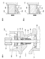
- FIG. 1 is a configuration diagram showing an example of the configuration of a main part of an internal combustion engine system to which the exhaust gas recirculation valve according to the first embodiment is applied.
- FIG. 2A is a configuration diagram showing an example of the configuration of the main part of the exhaust gas recirculation valve according to the first embodiment.
- 2B and 2C are enlarged views of the portion of the circle shown by the broken line in FIG. 2A.
- Embodiment 1 The exhaust gas recirculation valve 100 according to the first embodiment will be described with reference to FIGS. 1 and 2. With reference to FIG. 1, a configuration of a main part of the internal combustion engine system 1 to which the exhaust gas recirculation valve 100 according to the first embodiment is applied will be described.
- FIG. 1 is a configuration diagram showing an example of the configuration of a main part of an internal combustion engine system 1 to which the exhaust gas recirculation valve 100 according to the first embodiment is applied.
- the internal combustion engine system 1 according to the first embodiment includes an internal combustion engine 10, an intake pipe 20, an exhaust pipe 30, a turbocharger 40, an exhaust side circulation pipe 50, an intake side circulation pipe 60, and an exhaust gas recirculation valve 100.
- the internal combustion engine 10 is a prime mover such as a gasoline engine that burns fuel in a cylinder, uses combustion gas directly as a working fluid, and rotates a crankshaft by the heat energy thereof.
- the intake pipe 20 is a flow path pipe through which outside air sent to the internal combustion engine 10 flows.
- the exhaust pipe 30 is a flow path pipe through which the exhaust gas discharged from the internal combustion engine 10 flows.
- the turbocharger 40 is a turbocharger that uses the torque of a turbine that rotates in response to the flow of exhaust gas flowing through the exhaust pipe 30 to increase the flow rate of the outside air flowing through the intake pipe 20.
- the turbocharger 40 is not an essential configuration.
- the exhaust side circulation pipe 50 is a flow path pipe for circulating a part of the exhaust gas discharged from the internal combustion engine 10 to the intake pipe 20, and is a flow path pipe for the exhaust gas from the exhaust pipe 30 to the exhaust gas recirculation valve 100. It is a pipe that serves as a flow path.
- the intake side circulation pipe 60 is a flow path pipe for circulating a part of the exhaust gas discharged from the internal combustion engine 10 to the intake pipe 20, and is a flow path pipe for the exhaust gas from the exhaust gas recirculation valve 100 to the intake pipe 20. It is a pipe that serves as a flow path.
- the exhaust gas recirculation valve 100 is a poppet type valve that adjusts the inflow amount of the exhaust gas circulated in the intake pipe 20 in the exhaust gas recirculation mechanism. Since the exhaust gas recirculation mechanism and the exhaust gas recirculation technology are well known, the description thereof will be omitted.
- FIG. 2A is a configuration diagram showing an example of the configuration of the main part of the exhaust gas recirculation valve 100 according to the first embodiment.
- 2B and 2C are enlarged views of the portion of the circle shown by the broken line in FIG. 2A.
- the exhaust gas recirculation valve 100 includes an actuator 101, a housing 110, a valve shaft 120, a valve body 121, a valve seat 122, a first partition portion 130, a second partition portion 140, and a seal portion 150.
- 2A, 2B, and 2C are cross-sectional views of the exhaust gas recirculation valve 100 when the exhaust gas recirculation valve 100 is cut in a plane including the axis center of the valve shaft 120.
- the exhaust gas recirculation valve 100 may include a bearing 160, a seal portion 170 different from the seal portion 150, and a brush 180.
- the exhaust gas recirculation valve 100 will be described as including a bearing 160, a seal portion 170, and a brush 180.
- the seal portion 150 will be referred to as a first seal portion 150
- the seal portion 170 will be referred to as a second seal portion 170.
- the valve shaft 120 is projected from the actuator 101.
- the actuator 101 receives a control signal output by an ECU (Electronic Control Unit) (not shown) and directly moves the valve shaft 120 in the axial direction of the valve shaft 120 (hereinafter, simply referred to as “axial direction”).
- ECU Electronic Control Unit
- One end of the valve shaft 120 is fixed to the movable portion of the actuator 101, and the other end of the valve body 121 is fixed to the valve body 121.
- the valve shaft 120 moves linearly in the axial direction due to the movement of the movable portion of the actuator 101.
- the valve body 121 moves in the axial direction with the linear motion of the valve shaft 120.
- the housing 110 is a housing of the exhaust gas recirculation valve 100 and forms an exhaust gas flow path.
- a valve shaft 120 is inserted through the housing 110. That is, the housing 110 has a hole on the actuator 101 side through which the valve shaft 120 is inserted.
- the housing 110 is connected to the exhaust side circulation pipe 50 in the direction of arrow X shown in FIG. 2, and is connected to the intake side circulation pipe 60 in the direction of arrow Y shown in FIG.
- the housing 110 forms a flow path through which the exhaust gas that has flowed into the housing 110 from the exhaust side circulation pipe 50 flows out to the intake side circulation pipe 60.
- the valve seat 122 is a member that is fixed to the housing 110 and comes into contact with the valve body 121 when the valve is closed.
- the valve seat 122 abuts on the valve body 121 when the valve is closed to block the flow path formed in the housing 110, and when the valve is opened, the valve seat 122 is separated from the valve body 121 and is between the valve body 121 and the valve seat 122.
- a flow path through which exhaust gas passes is formed in the space of.
- the direction in which the valve shaft 120 moves linearly when the valve is opened from the closed state is referred to as the first direction, and the direction in which the valve shaft 120 directly moves when the valve is closed from the opened state. Is called the second direction.
- the first direction is the direction from the actuator 101 toward the valve body 121
- the second direction is the direction from the valve body 121 to the actuator 101. The direction to go.
- a valve shaft 120 is inserted in the bearing 160, and the valve shaft 120 is slid in the axial direction to stabilize the linear motion of the valve shaft 120.
- the brush 180 scrapes off powder particles such as soot contained in the exhaust gas adhering to the valve shaft 120 from the valve shaft 120.
- the second seal portion 170 has a hole through which the valve shaft 120 is inserted, and the hole is a side surface of the inserted valve shaft 120 and the valve shaft 120 in the radial direction (hereinafter, simply referred to as “diameter direction”). In the valve shaft 120, the valve shaft 120 is in contact with the entire circumferential direction (hereinafter, simply referred to as “circumferential direction”).
- the second seal portion 170 suppresses the exhaust gas flowing into the housing 110 from the exhaust side circulation pipe 50 from flowing around the valve shaft 120 in the direction in which the actuator 101 is arranged.
- the second seal portion 170 is made of a resin material such as PTFE (fluorocarbon resin).
- the actuator 101 is arranged while the exhaust gas is transmitted around the valve shaft 120 while maintaining the state in which the valve shaft 120 is tightened in the radial direction to the extent that the linear movement of the valve shaft 120 is not hindered. It suppresses the inflow in the direction of the exhaust.
- the exhaust gas flowing into the housing 110 passes through the gap through the slight gap between the second seal portion 170 and the valve shaft 120.
- the actuator 101 may flow in the direction in which the actuator 101 is arranged.
- the first partition portion 130 is a member provided on the inner wall of the housing 110 facing the side surface of the valve shaft 120 in the radial direction (hereinafter, simply referred to as “inner wall”) so as to surround the valve shaft 120 in the circumferential direction.
- the first partition portion 130 is a member having a first hole that protrudes from the inner wall toward the valve shaft 120 and has a gap between the inner wall and the valve shaft 120 through which the valve shaft 120 is inserted.
- the first partition 130 is composed of a flat plate having a first hole through which the valve shaft 120 is inserted.
- the first partition portion 130 is composed of a circular flat plate having a first hole.
- the first partition 130 is not limited to the one made of a flat plate.
- the second partition 140 has a valve shaft 120 in the circumferential direction on the inner wall of the inner wall facing the side surface of the valve shaft 120 in the radial direction, which is closer to the actuator 101 than the position where the first partition 130 is provided. It is a member provided by surrounding it. Specifically, it is a member that protrudes from the inner wall toward the valve shaft 120 and has a second hole through which the valve shaft 120 is inserted.
- the second partition portion 140 is composed of a bearing different from the bearing 160. When the second partition 140 is composed of bearings, the second partition 140 slides the valve shaft 120 in the axial direction. By forming the second partition portion 140 with a bearing, the linear motion of the valve shaft 120 can be stabilized.
- the second partition portion 140 is not limited to the one composed of bearings.
- the second partition portion 140 may be formed of a flat plate having a second hole through which the valve shaft 120 is inserted.
- the second partition portion 140 may be formed of a circular flat plate having a second hole.
- the second partition portion 140 will be described as being configured by a bearing.
- the seal portion 150 that is, the first seal portion 150 is a member provided on the side surface of the valve shaft 120 in the radial direction so as to surround the valve shaft 120 in the circumferential direction. Specifically, the first seal portion 150 projects from the side surface toward the inner wall, and when the valve shaft 120 moves linearly in the first direction, the first seal portion 150 comes into contact with the first partition portion 130, and the valve shaft 120 is the first. When it moves straight in the second direction, which is the opposite direction to the first direction, it comes into contact with the second partition portion 140. The first seal portion 150 is fixed to the valve shaft 120, for example.
- the exhaust gas recirculation valve 100 can suppress the exhaust gas flowing into the housing 110 from flowing in the direction in which the actuator 101 is arranged.
- the housing 110 is an air hole in the inner wall near the position where the first partition 130 is provided, and at a position closer to the valve body 121 than the position, to which a pipe communicating with the outside air is joined. You may have 111. With this configuration, the exhaust gas that has flowed into the space on the valve body side of the first partition portion 130 can be discharged to the outside air through the atmosphere hole 111.
- the first partition 130 is made of a metal material such as stainless steel, a thermoplastic resin, or the like. Since the first partition portion 130 is a member with which the first seal portion 150 repeatedly contacts, it is preferable that the first partition portion 130 is made of a metal material from the viewpoint of durability.
- first partition portion 130 may be integrally formed with a bush for fixing the second partition portion 140.
- the strength of the portion of the first partition 130 fixed to the inner wall is increased, and the durability of the first partition 130 is increased. It is possible to improve the sex.
- the surface of the first partition portion 130 on the valve body 121 side is inclined toward the valve body 121 side as the portion closer to the valve shaft 120. Is preferable. Since the surface of the first partition 130 on the valve body 121 side is inclined as shown in FIG. 2, the first partition 130 has exhaust gas flowing toward the valve body 121 side of the first partition 130. Can be guided toward the inner wall. As a result, since the surface of the first partition 130 on the valve body 121 side is inclined as shown in FIG. 2, in the exhaust gas recirculation valve 100, the exhaust gas flowing into the housing 110 is the actuator 101. Can be efficiently suppressed from flowing in the direction in which the gas is arranged.
- the first seal portion 150 is preferably made of PTFE, a thermoplastic resin, an elastic resin, silicone, or the like. Since the first seal portion 150 is made of a thermoplastic resin, an elastic resin, silicone, or the like, the exhaust gas flowing into the housing 110 is prevented from flowing in the direction in which the actuator 101 is arranged. It can be suppressed efficiently.
- the surface on the actuator 101 side is inclined toward the valve body 121 side as the portion closer to the inner wall facing the side surface of the valve shaft 120 in the radial direction. Is preferable. Since the surface of the first seal portion 150 on the actuator 101 side is inclined as shown in FIG. 2, the first seal portion 150 has a first seal when the valve shaft 120 moves linearly in the second direction. Exhaust gas that hits the surface of the unit 150 on the actuator 101 side can be guided toward the inner wall. As a result, since the surface of the first seal portion 150 on the actuator 101 side is inclined as shown in FIG. 2, the exhaust gas recirculation valve 100 has the exhaust gas flowing into the housing 110, and the actuator 101 has the exhaust gas flowing into the housing 110. It is possible to efficiently suppress the inflow in the arranged direction.
- the first seal portion 150 may not be fixed to the valve shaft 120 in the axial direction.
- the first seal portion 150 has a seal hole through which the valve shaft 120 is inserted, and the state is in contact with the first partition portion 130 or the second partition portion 140. While maintaining, it slides in the axial direction with respect to the valve shaft 120.
- the first seal portion 150 is made of, for example, PTFE.
- the exhaust gas recirculation valve 100 can shorten the distance between the first partition portion 130 and the second partition portion 140 with respect to the distance that the valve shaft 120 directly moves. Even if there is a processing error or an assembly error for each member, it is possible to efficiently suppress the exhaust gas flowing into the housing 110 from flowing in the direction in which the actuator 101 is arranged. Further, in the exhaust gas recirculation valve 100, the distance between the first partition portion 130 and the second partition portion 140 can be shortened with respect to the distance that the valve shaft 120 directly moves, so that the first seal portion 150 can be used.
- the distance between the and the first partition 130 can be reduced.
- the exhaust gas recirculation valve 100 causes the exhaust gas that has flowed into the housing 110 to flow in the direction in which the actuator 101 is arranged. Can be efficiently suppressed.
- the exhaust gas recirculation valve 100 is a poppet type exhaust gas recirculation valve 100, and is an actuator in which a valve shaft 120 having a valve body 121 fixed at one end and directly moving in the axial direction is provided.
- the circumferential direction of the valve shaft 120 is formed on the inner wall of the housing 110 which forms the flow path of the exhaust gas and is inserted into the valve shaft 120 and the housing 110 which faces the side surface of the valve shaft 120 in the radial direction of the valve shaft 120.
- a first partition 130 provided around the valve shaft 120, which protrudes from the inner wall toward the valve shaft 120 and has a gap between the valve shaft 120 and the valve shaft 120.
- the second partition portion 140 is provided so as to surround the valve shaft 120 in the circumferential direction, and has a second hole that protrudes from the inner wall toward the valve shaft 120 and has a second hole through which the valve shaft 120 is inserted.
- a seal portion 150 provided on the side surface of the partition portion 140 and the valve shaft 120 in the radial direction so as to surround the valve shaft 120 in the circumferential direction, and protrudes from the side surface toward the inner wall of the housing 110 and the valve shaft.
- the first partition portion 130 is configured by a flat plate having a first hole.
- the first partition portion 130 is configured by a circular flat plate having a first hole.
- the first partition portion 130 is integrally formed with the bush for fixing the second partition portion 140.
- the first partition portion 130 is configured such that the surface on the valve body 121 side is inclined toward the valve body 121 side as the portion closer to the valve shaft 120. ..
- the portion where the surface on the actuator 101 side is closer to the inner wall of the housing 110 facing the side surface of the valve shaft 120 in the radial direction is closer to the valve body 121 side. It was configured to incline toward.
- the exhaust gas recirculation valve 100 when the valve shaft 120 moves linearly, the exhaust gas flowing into the exhaust gas circulation valve is actuated while keeping the sliding resistance of the valve shaft 120 constant. It is possible to efficiently suppress the inflow to 101.
- the seal portion 150 has a seal hole through which the valve shaft 120 is inserted, and is in contact with the first partition portion 130 or the second partition portion 140. In the state, it was configured to slide in the axial direction with respect to the valve shaft 120 while maintaining the state. Further, with this configuration, the exhaust gas recirculation valve 100 has the exhaust gas flowing into the housing 110 in the direction in which the actuator 101 is arranged, even if there is a processing error or an assembly error for each member. It is possible to efficiently suppress the inflow.
- the second partition portion 140 is configured by a bearing that slides the valve shaft 120 in the axial direction.
- the exhaust gas recirculation valve according to this disclosure can be applied to an internal combustion engine system.
Landscapes
- Engineering & Computer Science (AREA)
- Mechanical Engineering (AREA)
- General Engineering & Computer Science (AREA)
- Chemical & Material Sciences (AREA)
- Combustion & Propulsion (AREA)
- Exhaust-Gas Circulating Devices (AREA)
- Lift Valve (AREA)
- Details Of Valves (AREA)
Priority Applications (3)
| Application Number | Priority Date | Filing Date | Title |
|---|---|---|---|
| CN202080101086.0A CN115667696B (zh) | 2020-06-02 | 2020-06-02 | 废气再循环阀 |
| PCT/JP2020/021839 WO2021245812A1 (ja) | 2020-06-02 | 2020-06-02 | 排気ガス再循環バルブ |
| JP2022528941A JP7154460B2 (ja) | 2020-06-02 | 2020-06-02 | 排気ガス再循環バルブ |
Applications Claiming Priority (1)
| Application Number | Priority Date | Filing Date | Title |
|---|---|---|---|
| PCT/JP2020/021839 WO2021245812A1 (ja) | 2020-06-02 | 2020-06-02 | 排気ガス再循環バルブ |
Publications (1)
| Publication Number | Publication Date |
|---|---|
| WO2021245812A1 true WO2021245812A1 (ja) | 2021-12-09 |
Family
ID=78830688
Family Applications (1)
| Application Number | Title | Priority Date | Filing Date |
|---|---|---|---|
| PCT/JP2020/021839 Ceased WO2021245812A1 (ja) | 2020-06-02 | 2020-06-02 | 排気ガス再循環バルブ |
Country Status (3)
| Country | Link |
|---|---|
| JP (1) | JP7154460B2 (cg-RX-API-DMAC7.html) |
| CN (1) | CN115667696B (cg-RX-API-DMAC7.html) |
| WO (1) | WO2021245812A1 (cg-RX-API-DMAC7.html) |
Citations (5)
| Publication number | Priority date | Publication date | Assignee | Title |
|---|---|---|---|---|
| JP2005120932A (ja) * | 2003-10-17 | 2005-05-12 | Mitsubishi Electric Corp | バルブ及び排気ガス再循環制御用バルブ又はバルブの組立て方法 |
| JP2012219903A (ja) * | 2011-04-07 | 2012-11-12 | Denso Corp | 弁装置 |
| JP2013185541A (ja) * | 2012-03-09 | 2013-09-19 | Aisan Industry Co Ltd | Egrバルブ |
| JP2013241965A (ja) * | 2012-05-18 | 2013-12-05 | Calsonic Kansei Corp | 流路切替機構 |
| JP2015161261A (ja) * | 2014-02-28 | 2015-09-07 | 愛三工業株式会社 | 流体制御弁及び新気導入装置 |
Family Cites Families (6)
| Publication number | Priority date | Publication date | Assignee | Title |
|---|---|---|---|---|
| JP4064390B2 (ja) * | 2004-09-22 | 2008-03-19 | 株式会社ケーヒン | 排気ガス再循環バルブ及びその密封装置 |
| JP2011252421A (ja) * | 2010-06-01 | 2011-12-15 | Aisan Industry Co Ltd | 排気ガス再循環装置 |
| JP6091364B2 (ja) * | 2013-07-09 | 2017-03-08 | 三菱電機株式会社 | 排気ガス再循環バルブ |
| JP2016023682A (ja) * | 2014-07-17 | 2016-02-08 | 三菱電機株式会社 | バルブ |
| JP2016080133A (ja) * | 2014-10-22 | 2016-05-16 | 大豊工業株式会社 | ダブルポペットバルブ |
| JP2017223292A (ja) * | 2016-06-15 | 2017-12-21 | 愛三工業株式会社 | 流量制御弁 |
-
2020
- 2020-06-02 JP JP2022528941A patent/JP7154460B2/ja active Active
- 2020-06-02 WO PCT/JP2020/021839 patent/WO2021245812A1/ja not_active Ceased
- 2020-06-02 CN CN202080101086.0A patent/CN115667696B/zh active Active
Patent Citations (5)
| Publication number | Priority date | Publication date | Assignee | Title |
|---|---|---|---|---|
| JP2005120932A (ja) * | 2003-10-17 | 2005-05-12 | Mitsubishi Electric Corp | バルブ及び排気ガス再循環制御用バルブ又はバルブの組立て方法 |
| JP2012219903A (ja) * | 2011-04-07 | 2012-11-12 | Denso Corp | 弁装置 |
| JP2013185541A (ja) * | 2012-03-09 | 2013-09-19 | Aisan Industry Co Ltd | Egrバルブ |
| JP2013241965A (ja) * | 2012-05-18 | 2013-12-05 | Calsonic Kansei Corp | 流路切替機構 |
| JP2015161261A (ja) * | 2014-02-28 | 2015-09-07 | 愛三工業株式会社 | 流体制御弁及び新気導入装置 |
Also Published As
| Publication number | Publication date |
|---|---|
| JPWO2021245812A1 (cg-RX-API-DMAC7.html) | 2021-12-09 |
| JP7154460B2 (ja) | 2022-10-17 |
| CN115667696B (zh) | 2025-05-09 |
| CN115667696A (zh) | 2023-01-31 |
Similar Documents
| Publication | Publication Date | Title |
|---|---|---|
| JP6391814B2 (ja) | 内燃機関のコンプレッサ用のブローオフ弁 | |
| JP6460012B2 (ja) | バルブ装置 | |
| JP6062129B2 (ja) | 流体制御バルブ | |
| CN103415683B (zh) | 致动器轴套管 | |
| JP2011043218A (ja) | 流体制御弁 | |
| WO2014068765A1 (ja) | バルブ | |
| JP5304825B2 (ja) | Egrバルブ | |
| US10378655B2 (en) | Valve device | |
| JP2019138354A (ja) | 冷却水制御弁装置 | |
| JP2017531140A (ja) | ブローオフ弁に用いられる調整機構 | |
| US12055223B2 (en) | Valve device | |
| JP2011196464A (ja) | ボール弁型バルブ装置 | |
| CN112334688B (zh) | 密封装置 | |
| CN103867346B (zh) | 用于车辆的废气再循环阀 | |
| JP7154460B2 (ja) | 排気ガス再循環バルブ | |
| US20190284990A1 (en) | Turbocharger | |
| US11286844B2 (en) | Valve assembly for a charging device | |
| JP2013185541A (ja) | Egrバルブ | |
| JP2018124136A (ja) | アクチュエータおよびシャフト連結構造 | |
| JP2005113872A (ja) | 排気ガス再循環装置 | |
| JP2022070328A (ja) | 排気ガス再循環バルブ | |
| JP2012052637A (ja) | 流体制御弁 | |
| JP2018100655A (ja) | ターボ用空圧式アクチュエータ | |
| JP2020028206A (ja) | 直動アクチュエータ、wgアクチュエータ、egrバルブ、及び可変翼制御用アクチュエータ | |
| JPWO2021245812A5 (cg-RX-API-DMAC7.html) |
Legal Events
| Date | Code | Title | Description |
|---|---|---|---|
| 121 | Ep: the epo has been informed by wipo that ep was designated in this application |
Ref document number: 20938660 Country of ref document: EP Kind code of ref document: A1 |
|
| ENP | Entry into the national phase |
Ref document number: 2022528941 Country of ref document: JP Kind code of ref document: A |
|
| NENP | Non-entry into the national phase |
Ref country code: DE |
|
| 122 | Ep: pct application non-entry in european phase |
Ref document number: 20938660 Country of ref document: EP Kind code of ref document: A1 |
|
| WWG | Wipo information: grant in national office |
Ref document number: 202080101086.0 Country of ref document: CN |