WO2021245735A1 - 集成材の接合構造 - Google Patents
集成材の接合構造 Download PDFInfo
- Publication number
- WO2021245735A1 WO2021245735A1 PCT/JP2020/021585 JP2020021585W WO2021245735A1 WO 2021245735 A1 WO2021245735 A1 WO 2021245735A1 JP 2020021585 W JP2020021585 W JP 2020021585W WO 2021245735 A1 WO2021245735 A1 WO 2021245735A1
- Authority
- WO
- WIPO (PCT)
- Prior art keywords
- column
- pillar
- laminated
- laminated wood
- slit
- Prior art date
Links
- 239000002023 wood Substances 0.000 title claims abstract description 29
- 238000010276 construction Methods 0.000 abstract description 29
- 239000002184 metal Substances 0.000 abstract description 19
- 230000000149 penetrating effect Effects 0.000 abstract description 3
- 239000000463 material Substances 0.000 description 9
- 230000033228 biological regulation Effects 0.000 description 5
- 230000008878 coupling Effects 0.000 description 4
- 238000010168 coupling process Methods 0.000 description 4
- 238000005859 coupling reaction Methods 0.000 description 4
- 238000005304 joining Methods 0.000 description 4
- 230000000694 effects Effects 0.000 description 2
- 238000000034 method Methods 0.000 description 2
- 229910000831 Steel Inorganic materials 0.000 description 1
- 238000005520 cutting process Methods 0.000 description 1
- 230000003831 deregulation Effects 0.000 description 1
- 238000010030 laminating Methods 0.000 description 1
- 238000004519 manufacturing process Methods 0.000 description 1
- 230000003014 reinforcing effect Effects 0.000 description 1
- 238000010008 shearing Methods 0.000 description 1
- 239000010959 steel Substances 0.000 description 1
- 238000003466 welding Methods 0.000 description 1
Images


Classifications
-
- E—FIXED CONSTRUCTIONS
- E04—BUILDING
- E04B—GENERAL BUILDING CONSTRUCTIONS; WALLS, e.g. PARTITIONS; ROOFS; FLOORS; CEILINGS; INSULATION OR OTHER PROTECTION OF BUILDINGS
- E04B1/00—Constructions in general; Structures which are not restricted either to walls, e.g. partitions, or floors or ceilings or roofs
- E04B1/18—Structures comprising elongated load-supporting parts, e.g. columns, girders, skeletons
- E04B1/26—Structures comprising elongated load-supporting parts, e.g. columns, girders, skeletons the supporting parts consisting of wood
- E04B1/2604—Connections specially adapted therefor
- E04B1/2612—Joist hangers
-
- E—FIXED CONSTRUCTIONS
- E04—BUILDING
- E04B—GENERAL BUILDING CONSTRUCTIONS; WALLS, e.g. PARTITIONS; ROOFS; FLOORS; CEILINGS; INSULATION OR OTHER PROTECTION OF BUILDINGS
- E04B1/00—Constructions in general; Structures which are not restricted either to walls, e.g. partitions, or floors or ceilings or roofs
- E04B1/18—Structures comprising elongated load-supporting parts, e.g. columns, girders, skeletons
- E04B1/20—Structures comprising elongated load-supporting parts, e.g. columns, girders, skeletons the supporting parts consisting of concrete, e.g. reinforced concrete, or other stonelike material
- E04B1/21—Connections specially adapted therefor
-
- E—FIXED CONSTRUCTIONS
- E04—BUILDING
- E04B—GENERAL BUILDING CONSTRUCTIONS; WALLS, e.g. PARTITIONS; ROOFS; FLOORS; CEILINGS; INSULATION OR OTHER PROTECTION OF BUILDINGS
- E04B1/00—Constructions in general; Structures which are not restricted either to walls, e.g. partitions, or floors or ceilings or roofs
- E04B1/18—Structures comprising elongated load-supporting parts, e.g. columns, girders, skeletons
- E04B1/24—Structures comprising elongated load-supporting parts, e.g. columns, girders, skeletons the supporting parts consisting of metal
- E04B1/2403—Connection details of the elongated load-supporting parts
-
- E—FIXED CONSTRUCTIONS
- E04—BUILDING
- E04B—GENERAL BUILDING CONSTRUCTIONS; WALLS, e.g. PARTITIONS; ROOFS; FLOORS; CEILINGS; INSULATION OR OTHER PROTECTION OF BUILDINGS
- E04B1/00—Constructions in general; Structures which are not restricted either to walls, e.g. partitions, or floors or ceilings or roofs
- E04B1/18—Structures comprising elongated load-supporting parts, e.g. columns, girders, skeletons
- E04B1/26—Structures comprising elongated load-supporting parts, e.g. columns, girders, skeletons the supporting parts consisting of wood
- E04B1/2604—Connections specially adapted therefor
-
- E—FIXED CONSTRUCTIONS
- E04—BUILDING
- E04B—GENERAL BUILDING CONSTRUCTIONS; WALLS, e.g. PARTITIONS; ROOFS; FLOORS; CEILINGS; INSULATION OR OTHER PROTECTION OF BUILDINGS
- E04B1/00—Constructions in general; Structures which are not restricted either to walls, e.g. partitions, or floors or ceilings or roofs
- E04B1/38—Connections for building structures in general
- E04B1/48—Dowels, i.e. members adapted to penetrate the surfaces of two parts and to take the shear stresses
- E04B1/486—Shear dowels for wood
-
- E—FIXED CONSTRUCTIONS
- E04—BUILDING
- E04B—GENERAL BUILDING CONSTRUCTIONS; WALLS, e.g. PARTITIONS; ROOFS; FLOORS; CEILINGS; INSULATION OR OTHER PROTECTION OF BUILDINGS
- E04B1/00—Constructions in general; Structures which are not restricted either to walls, e.g. partitions, or floors or ceilings or roofs
- E04B1/38—Connections for building structures in general
- E04B1/58—Connections for building structures in general of bar-shaped building elements
-
- E—FIXED CONSTRUCTIONS
- E04—BUILDING
- E04B—GENERAL BUILDING CONSTRUCTIONS; WALLS, e.g. PARTITIONS; ROOFS; FLOORS; CEILINGS; INSULATION OR OTHER PROTECTION OF BUILDINGS
- E04B1/00—Constructions in general; Structures which are not restricted either to walls, e.g. partitions, or floors or ceilings or roofs
- E04B1/18—Structures comprising elongated load-supporting parts, e.g. columns, girders, skeletons
- E04B1/26—Structures comprising elongated load-supporting parts, e.g. columns, girders, skeletons the supporting parts consisting of wood
- E04B1/2604—Connections specially adapted therefor
- E04B2001/2644—Brackets, gussets or joining plates
- E04B2001/2648—Brackets, gussets or joining plates located in slots of the elongated wooden members
-
- E—FIXED CONSTRUCTIONS
- E04—BUILDING
- E04B—GENERAL BUILDING CONSTRUCTIONS; WALLS, e.g. PARTITIONS; ROOFS; FLOORS; CEILINGS; INSULATION OR OTHER PROTECTION OF BUILDINGS
- E04B1/00—Constructions in general; Structures which are not restricted either to walls, e.g. partitions, or floors or ceilings or roofs
- E04B1/18—Structures comprising elongated load-supporting parts, e.g. columns, girders, skeletons
- E04B1/26—Structures comprising elongated load-supporting parts, e.g. columns, girders, skeletons the supporting parts consisting of wood
- E04B1/2604—Connections specially adapted therefor
- E04B2001/266—Socket type connectors
Definitions
- the present invention relates to a bonded structure of laminated lumber.
- the basic construction types of wooden buildings include the so-called conventional frame construction method, frame wall construction method, and log construction method.
- the building standard law, the enforcement order of the law, the notification of the Ministry of Construction, etc. have conventionally stipulated the material type, dimensions, arrangement, joining form and other specifications of structural members in detail and concretely.
- a construction method for wooden construction there are also a prefab construction method and a panel construction method in which structural strength elements such as floors and walls are collectively produced in advance at a factory and assembled on site.
- specifications such as the Building Standards Act are applied to those based on the conventional framework construction method and frame wall construction method, but for construction methods related to special structures that are not envisioned by law. , Needed to be individually certified by the Minister of Construction.
- Glulam formed by laminating and adhering lamina is superior in strength and dimensional stability compared to natural lumber, has high designability and formability, and has a great effect of contributing to the effective utilization of forest resources. Therefore, the demand has been increasing in recent years, and there is a demand for the development of a new construction method for wooden houses that fully utilizes the advantages of this laminated lumber.
- the present invention has been made in view of such circumstances, and as a novel construction method suitable for a relatively small-scale wooden building such as a house, a structure having a rigid frame structure as a basic form and a structure having a medium cross section or a small cross section is used.
- the purpose is to provide a laminated wood construction method using laminated wood. Therefore, it is an object of the present invention to disclose a specific configuration of a joint structure of a column made of laminated wood and a beam as one of the structural strength elements of the laminated wood construction method.
- the present invention is a joint structure in which a column and a beam made of laminated wood having a medium cross section or a small cross section are rigidly joined by a pair of connecting metal fittings in a beam-winning state, and each connecting metal fitting is a joint structure. It is formed by connecting a plate part and a pipe part having fixing holes for drift pins or bolts in a wing plate shape, while a slit opening in the end face of the pillar is formed in the width direction of the pillar at the end of the pillar.
- grooves penetrating in the beam cross-section direction are formed at two locations with appropriate intervals in the beam-to-beam direction, and the pipe portion of the pair of connecting hardware is fitted into each groove.
- the plate portion is fitted into the slit of the column and fixed to the column and the beam by using a drift pin or a bolt, respectively, whereby the column and the beam are rigidly joined.
- a subsidy may be further arranged in the middle of the pair of connecting hardware, and both ends of the subsidy may be fixed to columns and beams by drift pins or bolts, respectively.
- the connecting hardware may be provided with a plurality of pipe portions for one plate portion, and each pipe portion may be formed so as to extend in parallel from one side of the plate portion.
- a flat plate-shaped connecting plate is connected to the pipe portion of the connecting hardware, and the connecting plate is connected to the slit formed at the lower end of the column of the upper layer portion. It may be erected on the beam by fitting.
- the "small cross-section laminated lumber” means a lumber having a short side of less than 7.5 cm or a long side of less than 15 cm.
- the present invention defines the cross-sectional size of structural laminated lumber based on this standard.
- the joint structure of the laminated wood of the present invention is such that a column and a beam made of a medium-section or small-section laminated wood are rigidly joined in a beam-winning state by a pair of connecting hardware having a plate portion and a pipe portion. Therefore, the structural skeleton constructed by combining these is superior in strength and has high rigidity as compared with the general conventional frame construction method constructed by using natural lumber.
- the initial rigidity of the joint portion is significantly increased as compared with the conventional case due to the sinking of the drift pin or bolt into the joint portion and the surface pressure effect at the contact portion between the beam and the column end surface.
- the degree of freedom in design regarding the arrangement of columns and bearing walls is increased, and it becomes possible to omit reinforcing members such as streaks, canes, and flints, forming a large-span space and a large opening with a large frontage.
- reinforcing members such as streaks, canes, and flints
- a pair of connecting hardware is used for the joint between the column and the beam, and these are connected to the column and the beam by bolts and drift pins, so that the joint is processed and assembled. Is easy and the processing accuracy is high. As a result, the construction time at the site can be shortened.
- the medium-section or small-section laminated lumber used for columns and beams has excellent design and has a different taste from natural lumber. It is possible to form a unique space that combines the warm texture of the wood with a bold and powerful impression.
- the depth of the slit formed in the column can be made shallower than in the conventional case, and the mortise of the beam can be easily formed. It is possible to reduce the cost and labor required.
- the glulam joint structure of the present invention is a glulam joint structure related to a joint between columns and beams in a glulam ramen frame, which is a structural frame based on a rigid frame structure, and the columns and beams are a medium-section or small-section assembly. It is formed by a single piece of wood. By combining a plurality of sets of this laminated lumber frame, the laminated lumber construction method intended by the present invention can be realized.
- the shape of the rigid frame can be gate-shaped, chevron-shaped, trapezoidal, etc., and can be single-layered or multi-layered.
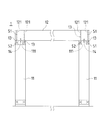
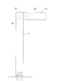
- FIG. 1 is a front view of the laminated lumber ramen frame
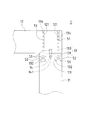
- FIG. 2 is a top view of the laminated lumber ramen frame
- FIG. 3 is a side view of the laminated lumber ramen frame
- FIG. 4 is a partial front view of the laminated lumber ramen frame
- FIG. 5 is a perspective view of connecting hardware.
- the laminated glulam ramen frame 1 exemplified is a beam-winning gate-shaped glulam with a span of about 3 m.
- the column 11 has a cross section of 105 mm (column thickness) ⁇ 390 mm (column width), and the beam 12 has a cross section of 105 mm.
- (Beam width) x 390 mm (beam) medium cross-section laminated wood is used as a single material.
- the cross-sectional dimensions of the columns 11 and the beams 12 are not limited to this, and small cross-sectional laminated lumber can be used when the span is small.
- the practical span size can be up to about 7 m.
- Each connecting hardware 13 includes a steel plate portion 131 and a pipe portion 133, and fixing holes 132 and 134 for drift pins or bolts are formed in each of the connecting hardware 13.
- the connecting hardware 13 is formed by integrating the plate portion 131 and the pipe portion 133 into a battledore shape by welding or the like, and the pipe portion 133 extends coaxially with the plate portion from one side of the plate portion 131. ..
- the fixing hole 132 provided in the plate portion 131 and the fixing hole 134 provided in the pipe portion 133 are formed so as to penetrate in the same direction.
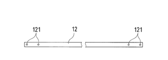
- a slit 111 that opens to the end surface of the column is formed in the column width direction (left-right direction in FIG. 1), and a hole having substantially the same diameter as the pipe portion 133 of the connecting hardware 13 (not shown). ) Is formed in the vicinity of both ends of the slit 111. Further, in the contact portion of the column end surface of the beam 12, tenon holes 121 penetrating in the beam direction are formed at two locations at appropriate intervals in the beam-to-beam direction. In the connecting hardware 13, each pipe portion 133 is fitted into each mortise hole 121 of the beam 12, while the plate portion 131 is fitted into the slit 111 of the pillar 11.
- each connecting hardware 13 inserted across the pillar 11 and the beam 12 is inserted from the side surface (front or back surface in FIG. 1) of the pillar 11 and the beam 12 via a plurality of drift pins 51 and bolts 52. It is integrally joined with the 11 and the beam 12.
- the drift pin 51 and the bolt 52 secure the strength of the joint portion by the shear strength thereof, but the bolt 52 has a function of tightening the material end portion where the slit 111, the mortise hole 121, etc.
- the subsidy 14 may be arranged in the middle of the connecting hardware 13 arranged at intervals as described above.
- the subsidy 14 is formed, for example, into a cylindrical shape having substantially the same diameter as the pipe portion 133 of the connecting metal fitting 13, or a flat plate shape having substantially the same thickness as the plate portion 131 of the connecting metal fitting 13, and is fixed to both ends for drift pins or bolts. It is provided with a hole 141. Both ends of the auxiliary metal fitting 14 are inserted into slits 111 formed in the pillar 11 and slits or holes (not shown) formed in the beam 12, and are fixed by drift pins 51 or bolts 52, respectively, like the connecting metal fitting 13. Will be done.
- the joint structure of the column and the beam a form in which the joint plate 73 is inserted over the entire width of the beam and the column is also possible as in the conventional form shown in FIG.
- a circular saw having a large diameter around 1 m in diameter
- the depth of the slit 111 formed on the end face of the pillar is only about half to one-third of the width of the pillar, so that it is possible to process with a circular saw having a diameter of up to about 30 cm.
- FIG. 6 and 7 show a second embodiment of the present invention. Since this embodiment is different from the first embodiment in the form of the connecting hardware, the different parts will be described, and the other parts will be omitted in detail by using the same reference numerals. ..
- the connecting hardware 23 includes two pipe portions 233 for one plate portion 231.
- Each pipe portion 233 is integrally formed with the plate portion 231 so as to extend in parallel from one side of the plate portion 231.
- the plate portion 231 is provided with a plurality of fixing holes 232. Further, as shown in FIG. 6, the fixing holes 234 formed in each of the pipe portions 233 are not formed in the same positions corresponding to each other, but are formed in positions shifted from each other in height. Will be done.
- the mortises 121 formed at the joints of the beams 12 correspond to the shape of the connecting hardware 23, and are formed at two locations at predetermined intervals in the beam-to-beam direction.
- the pipe portion 233 is fitted into each mortise hole 121, while the plate portion 231 is fitted into the slit 111.
- a plurality of drift pins 51 or bolts 52 are driven from the side surfaces of the pillar 11 and the beam 12, and each connecting hardware 23 is integrally joined to the pillar 11 and the beam 12.
- a long hole 236 is provided on the lower end side of each pipe portion 233.
- the elongated hole 236 is formed by cutting out the lower end of the pipe portion 233 in an elongated shape, and is formed on both the front side and the back surface side of the pipe portion 233.
- the elongated hole 236 is provided to reduce the yield strength at the joint portion between the plate portion 231 and the pipe portion 233. As a result, when an excessive load is applied to the joint portion between the column 11 and the beam 12, the splitting that occurs in these woods is prevented.
- the slit 111 formed in the pillar 11 can be processed with a circular saw having a small diameter up to about 30 cm in diameter, so that the slit processing can be easily performed. can do.
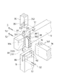
- FIG. 8 is an exploded perspective view showing a third embodiment of the present invention.
- This embodiment is a joint structure in which a lower layer column 11 and an upper layer column 35 are erected on a beam 12 of a laminated lumber frame 1 via a connecting hardware 33 and a connecting plate 37.
- the connecting metal fitting 33 includes a pipe portion 333 and a plate portion 331 integrated in a battledore shape, and has a slit at the other end of the pipe portion 333.
- the holding portion 335 to be held is formed.
- a fixing hole 336 is provided at the end of the holding portion 335, and the coupling plate 37 is connected to the holding portion 335 via the fixing hole 336.
- the coupling plate 37 is a flat plate piece and is provided with a plurality of fixing holes 371 for inserting a drift pin 51 or the like.
- the pipe portion 333 is first inserted into the mortise hole 121 from the lower surface side of the beam 12, and is fixed to the beam 12 by the bolt 52 inserted from the side surface of the beam 12.
- the plate portion 331 and the lower end of the pipe portion 333 protruding toward the lower surface side of the beam 12 are inserted into the slit 111 and the hole portion 112 formed in the upper end portion of the pillar 11 in the lower layer portion, and are inserted from the front surface or the back surface of the pillar 11. It is fixed to the pillar 11 by the drift pin 51 or the bolt 52.
- the connecting plate 37 is inserted into the holding portion 335 at the upper end of the pipe portion 333 from the top surface side of the beam 12, and the pillar 35 in the upper layer portion is inserted into the connecting plate 37.
- the slit 351 and the hole portion 352 formed at the lower end of the pillar 35 of the upper layer portion project to the top surface side of the beam 12.
- the pipe portion 333, the coupling plate 37, and the pillar 35 are integrally fixed by the drift pin 51 or the bolt 52 fitted from the front surface or the back surface of the pillar 35 in the upper layer portion. In this way, the upper and lower columns 11 and 35 are connected with the beam 12 in between.
- the joining metal fitting 38 as illustrated can also be used.
- the metal joint 38 has a back plate 381 and a pair of side plates 382 orthogonal to the back plate 381.
- the back plate 381 is applied to the side surface of the beam 12, and is fastened together with bolts 52 for fixing the connecting hardware 33 to be fixed to the beam 12.
- the side plate 382 projecting to the side of the beam 12 is inserted into the slit 361 formed at the end of the horizontal member 36, and is laid horizontally via the drift pin 51 or the bolt 52 inserted from the side surface of the horizontal member 36. It is connected to the material 36.
Abstract
Description
111 スリット
12 梁
121 ほぞ孔
13 結金物
131 プレート部
132 固定孔
133 パイプ部
134 固定孔
14 補助金物
37 結合プレート
51 ドリフトピン
52 ボルト
Claims (4)
- 中断面又は小断面集成材からなる柱と梁とが一対の連結金物によって梁勝ち状態に剛接合される接合構造であって、
各連結金物は、ドリフトピン又はボルト用の固定孔をそれぞれ有するプレート部及びパイプ部を羽子板状に結合して形成される一方、
柱の端部には柱端面に開口するスリットが柱幅方向に形成されるとともに、梁における柱端面の当接部には梁せい方向に貫通するほぞ孔が梁間方向に適宜間隔を設けて2箇所に形成され、
前記一対の連結金物のパイプ部を各ほぞ孔に嵌入するとともに、プレート部を柱のスリットに嵌入し、ドリフトピン又はボルトを用いて柱と梁にそれぞれ固定することにより柱と梁が剛接合されることを特徴とする集成材の接合構造。 - 請求項1に記載の接合構造において、対をなす連結金物の中間に補助金物が配置され、この補助金物の両端が柱と梁にそれぞれドリフトピン又はボルトによって固定されたことを特徴とする集成材の接合構造。
- 連結金物は、一枚のプレート部に対し複数のパイプ部を備え、各パイプ部がプレート部の一側辺から並行に延出するように形成されたことを特徴とする請求項1又は2に記載の集成材の接合構造。
- 下層部の柱に接合された梁の天面側において、連結金物のパイプ部に平板状の結合プレートが接続され、上層部の柱がその下端部に形成されたスリットに前記結合プレートを嵌入することにより梁上に立設されることを特徴とする請求項1から3のいずれかに記載の集成材の接合構造。
Priority Applications (4)
| Application Number | Priority Date | Filing Date | Title |
|---|---|---|---|
| GB2200154.9A GB2618054A (en) | 2020-06-01 | 2020-06-01 | Laminated wood joint structure |
| PCT/JP2020/021585 WO2021245735A1 (ja) | 2020-06-01 | 2020-06-01 | 集成材の接合構造 |
| US17/622,657 US20230083082A1 (en) | 2020-06-01 | 2020-06-01 | Connection structure for glued laminated timber |
| AU2020451349A AU2020451349A1 (en) | 2020-06-01 | 2020-06-01 | Laminated wood joint structure |
Applications Claiming Priority (1)
| Application Number | Priority Date | Filing Date | Title |
|---|---|---|---|
| PCT/JP2020/021585 WO2021245735A1 (ja) | 2020-06-01 | 2020-06-01 | 集成材の接合構造 |
Publications (1)
| Publication Number | Publication Date |
|---|---|
| WO2021245735A1 true WO2021245735A1 (ja) | 2021-12-09 |
Family
ID=78830973
Family Applications (1)
| Application Number | Title | Priority Date | Filing Date |
|---|---|---|---|
| PCT/JP2020/021585 WO2021245735A1 (ja) | 2020-06-01 | 2020-06-01 | 集成材の接合構造 |
Country Status (4)
| Country | Link |
|---|---|
| US (1) | US20230083082A1 (ja) |
| AU (1) | AU2020451349A1 (ja) |
| GB (1) | GB2618054A (ja) |
| WO (1) | WO2021245735A1 (ja) |
Citations (1)
| Publication number | Priority date | Publication date | Assignee | Title |
|---|---|---|---|---|
| JP2003328437A (ja) * | 2002-05-08 | 2003-11-19 | Sekisui House Ltd | 集成材の接合構造 |
Family Cites Families (10)
| Publication number | Priority date | Publication date | Assignee | Title |
|---|---|---|---|---|
| US5469678A (en) * | 1990-06-18 | 1995-11-28 | Zamerovsky; Edward | Method for constructing a frame structure with load-bearing joints |
| US5660492A (en) * | 1993-12-18 | 1997-08-26 | Bathon; Leander | Coupling for wood structural members |
| US5636934A (en) * | 1994-06-21 | 1997-06-10 | Kyoto Mokuzou Kenchiku Kenkyuusho | Structural connector, and method of making structural joint |
| JP3066734B2 (ja) * | 1996-11-15 | 2000-07-17 | 株式会社ウエスト | 木造の建物の軸組用装置 |
| JP5634732B2 (ja) * | 2010-04-01 | 2014-12-03 | 大倉 憲峰 | 締結金物 |
| JP5822262B2 (ja) * | 2011-06-30 | 2015-11-24 | 住友林業株式会社 | 梁勝ち接合部における柱梁接合構造 |
| JP5995466B2 (ja) * | 2012-03-12 | 2016-09-21 | 住友林業株式会社 | 木造建築構造躯体 |
| DE102016204921A1 (de) * | 2016-03-24 | 2017-09-28 | Swg Schraubenwerk Gaisbach Gmbh | Verbinder und Verfahren zum Verbinden von Balken aus Holzwerkstoff |
| US20180119413A1 (en) * | 2016-10-31 | 2018-05-03 | Jin-Jie Lin | Concealed Post Tie |
| WO2021245736A1 (ja) * | 2020-06-01 | 2021-12-09 | 積水ハウス株式会社 | 接合金物 |
-
2020
- 2020-06-01 WO PCT/JP2020/021585 patent/WO2021245735A1/ja active Application Filing
- 2020-06-01 GB GB2200154.9A patent/GB2618054A/en not_active Withdrawn
- 2020-06-01 US US17/622,657 patent/US20230083082A1/en active Pending
- 2020-06-01 AU AU2020451349A patent/AU2020451349A1/en active Pending
Patent Citations (1)
| Publication number | Priority date | Publication date | Assignee | Title |
|---|---|---|---|---|
| JP2003328437A (ja) * | 2002-05-08 | 2003-11-19 | Sekisui House Ltd | 集成材の接合構造 |
Also Published As
| Publication number | Publication date |
|---|---|
| AU2020451349A1 (en) | 2022-02-03 |
| GB2618054A (en) | 2023-11-01 |
| US20230083082A1 (en) | 2023-03-16 |
Similar Documents
| Publication | Publication Date | Title |
|---|---|---|
| JP3581426B2 (ja) | 木造建築物の構造材と床構造及び屋根構造並びにそれらを用いた構築工法 | |
| JP2007092318A (ja) | 木製構造材の仕口構造、横架材、柱脚構造および柱脚金具、並びにこれらを備えた木造建築物の軸組およびその組立て方法 | |
| JP6841439B2 (ja) | 建築工法および建築構造 | |
| JP6595146B1 (ja) | 建築物およびその建築工法 | |
| JP2987768B2 (ja) | 建築物における構造用集成材及び骨組構造用建築部材 | |
| WO2021245735A1 (ja) | 集成材の接合構造 | |
| JP3866148B2 (ja) | 集成材の接合構造及び連結金物 | |
| JP5749588B2 (ja) | 柱と梁の接合構造 | |
| JP2007284918A (ja) | 横架体および木造構造物 | |
| JP4034322B2 (ja) | 木材の連結構造及びこれを用いた木造建築物用構造体 | |
| JPH0791863B2 (ja) | 建築物の木造骨組構造 | |
| JP2948716B2 (ja) | 木造軸組パネル構造 | |
| JP2003239382A (ja) | 集成材構法 | |
| JP7083066B1 (ja) | 木質架構および建物の骨組み | |
| JP3922930B2 (ja) | 構造用複合材 | |
| JP5650383B2 (ja) | 多段組子接合軸組 | |
| JP2000234407A (ja) | 木造門型フレームを用いた耐震壁構造 | |
| JP2977494B2 (ja) | 門型フレームおよびその組立て方法 | |
| JP2022051464A (ja) | 壁面構造 | |
| JPH06185116A (ja) | 集成材構造における柱・梁接合部構造及び柱・梁架構 | |
| JP4602031B2 (ja) | 壁用パネル | |
| JP2021161620A (ja) | 耐力壁構造 | |
| JP3538151B2 (ja) | 軸組構造、躯体構造 | |
| JPH07259183A (ja) | 建物の柱接合構造 | |
| JP2014214497A (ja) | 木質梁接合構造及び木質梁接合方法 |
Legal Events
| Date | Code | Title | Description |
|---|---|---|---|
| ENP | Entry into the national phase |
Ref document number: 202200154 Country of ref document: GB Kind code of ref document: A Free format text: PCT FILING DATE = 20200601 |
|
| 121 | Ep: the epo has been informed by wipo that ep was designated in this application |
Ref document number: 20938841 Country of ref document: EP Kind code of ref document: A1 |
|
| ENP | Entry into the national phase |
Ref document number: 2020451349 Country of ref document: AU Date of ref document: 20200601 Kind code of ref document: A |
|
| NENP | Non-entry into the national phase |
Ref country code: DE |
|
| 122 | Ep: pct application non-entry in european phase |
Ref document number: 20938841 Country of ref document: EP Kind code of ref document: A1 |
|
| NENP | Non-entry into the national phase |
Ref country code: JP |