WO2021241228A1 - 基板処理方法および基板処理装置 - Google Patents
基板処理方法および基板処理装置 Download PDFInfo
- Publication number
- WO2021241228A1 WO2021241228A1 PCT/JP2021/018027 JP2021018027W WO2021241228A1 WO 2021241228 A1 WO2021241228 A1 WO 2021241228A1 JP 2021018027 W JP2021018027 W JP 2021018027W WO 2021241228 A1 WO2021241228 A1 WO 2021241228A1
- Authority
- WO
- WIPO (PCT)
- Prior art keywords
- substrate
- image data
- monitoring
- nozzle
- processing
- Prior art date
Links
Images


Classifications
-
- B—PERFORMING OPERATIONS; TRANSPORTING
- B05—SPRAYING OR ATOMISING IN GENERAL; APPLYING FLUENT MATERIALS TO SURFACES, IN GENERAL
- B05B—SPRAYING APPARATUS; ATOMISING APPARATUS; NOZZLES
- B05B12/00—Arrangements for controlling delivery; Arrangements for controlling the spray area
- B05B12/08—Arrangements for controlling delivery; Arrangements for controlling the spray area responsive to condition of liquid or other fluent material to be discharged, of ambient medium or of target ; responsive to condition of spray devices or of supply means, e.g. pipes, pumps or their drive means
- B05B12/084—Arrangements for controlling delivery; Arrangements for controlling the spray area responsive to condition of liquid or other fluent material to be discharged, of ambient medium or of target ; responsive to condition of spray devices or of supply means, e.g. pipes, pumps or their drive means responsive to condition of liquid or other fluent material already sprayed on the target, e.g. coating thickness, weight or pattern
-
- B—PERFORMING OPERATIONS; TRANSPORTING
- B05—SPRAYING OR ATOMISING IN GENERAL; APPLYING FLUENT MATERIALS TO SURFACES, IN GENERAL
- B05C—APPARATUS FOR APPLYING FLUENT MATERIALS TO SURFACES, IN GENERAL
- B05C11/00—Component parts, details or accessories not specifically provided for in groups B05C1/00 - B05C9/00
- B05C11/10—Storage, supply or control of liquid or other fluent material; Recovery of excess liquid or other fluent material
-
- H—ELECTRICITY
- H01—ELECTRIC ELEMENTS
- H01L—SEMICONDUCTOR DEVICES NOT COVERED BY CLASS H10
- H01L21/00—Processes or apparatus adapted for the manufacture or treatment of semiconductor or solid state devices or of parts thereof
- H01L21/67—Apparatus specially adapted for handling semiconductor or electric solid state devices during manufacture or treatment thereof; Apparatus specially adapted for handling wafers during manufacture or treatment of semiconductor or electric solid state devices or components ; Apparatus not specifically provided for elsewhere
- H01L21/67005—Apparatus not specifically provided for elsewhere
- H01L21/67242—Apparatus for monitoring, sorting or marking
- H01L21/67253—Process monitoring, e.g. flow or thickness monitoring
-
- B—PERFORMING OPERATIONS; TRANSPORTING
- B05—SPRAYING OR ATOMISING IN GENERAL; APPLYING FLUENT MATERIALS TO SURFACES, IN GENERAL
- B05C—APPARATUS FOR APPLYING FLUENT MATERIALS TO SURFACES, IN GENERAL
- B05C11/00—Component parts, details or accessories not specifically provided for in groups B05C1/00 - B05C9/00
- B05C11/02—Apparatus for spreading or distributing liquids or other fluent materials already applied to a surface ; Controlling means therefor; Control of the thickness of a coating by spreading or distributing liquids or other fluent materials already applied to the coated surface
- B05C11/08—Spreading liquid or other fluent material by manipulating the work, e.g. tilting
-
- H—ELECTRICITY
- H01—ELECTRIC ELEMENTS
- H01L—SEMICONDUCTOR DEVICES NOT COVERED BY CLASS H10
- H01L21/00—Processes or apparatus adapted for the manufacture or treatment of semiconductor or solid state devices or of parts thereof
- H01L21/02—Manufacture or treatment of semiconductor devices or of parts thereof
- H01L21/027—Making masks on semiconductor bodies for further photolithographic processing not provided for in group H01L21/18 or H01L21/34
-
- H—ELECTRICITY
- H01—ELECTRIC ELEMENTS
- H01L—SEMICONDUCTOR DEVICES NOT COVERED BY CLASS H10
- H01L21/00—Processes or apparatus adapted for the manufacture or treatment of semiconductor or solid state devices or of parts thereof
- H01L21/02—Manufacture or treatment of semiconductor devices or of parts thereof
- H01L21/04—Manufacture or treatment of semiconductor devices or of parts thereof the devices having at least one potential-jump barrier or surface barrier, e.g. PN junction, depletion layer or carrier concentration layer
- H01L21/18—Manufacture or treatment of semiconductor devices or of parts thereof the devices having at least one potential-jump barrier or surface barrier, e.g. PN junction, depletion layer or carrier concentration layer the devices having semiconductor bodies comprising elements of Group IV of the Periodic System or AIIIBV compounds with or without impurities, e.g. doping materials
- H01L21/30—Treatment of semiconductor bodies using processes or apparatus not provided for in groups H01L21/20 - H01L21/26
- H01L21/302—Treatment of semiconductor bodies using processes or apparatus not provided for in groups H01L21/20 - H01L21/26 to change their surface-physical characteristics or shape, e.g. etching, polishing, cutting
- H01L21/304—Mechanical treatment, e.g. grinding, polishing, cutting
-
- H—ELECTRICITY
- H01—ELECTRIC ELEMENTS
- H01L—SEMICONDUCTOR DEVICES NOT COVERED BY CLASS H10
- H01L21/00—Processes or apparatus adapted for the manufacture or treatment of semiconductor or solid state devices or of parts thereof
- H01L21/02—Manufacture or treatment of semiconductor devices or of parts thereof
- H01L21/04—Manufacture or treatment of semiconductor devices or of parts thereof the devices having at least one potential-jump barrier or surface barrier, e.g. PN junction, depletion layer or carrier concentration layer
- H01L21/18—Manufacture or treatment of semiconductor devices or of parts thereof the devices having at least one potential-jump barrier or surface barrier, e.g. PN junction, depletion layer or carrier concentration layer the devices having semiconductor bodies comprising elements of Group IV of the Periodic System or AIIIBV compounds with or without impurities, e.g. doping materials
- H01L21/30—Treatment of semiconductor bodies using processes or apparatus not provided for in groups H01L21/20 - H01L21/26
- H01L21/302—Treatment of semiconductor bodies using processes or apparatus not provided for in groups H01L21/20 - H01L21/26 to change their surface-physical characteristics or shape, e.g. etching, polishing, cutting
- H01L21/306—Chemical or electrical treatment, e.g. electrolytic etching
-
- H—ELECTRICITY
- H01—ELECTRIC ELEMENTS
- H01L—SEMICONDUCTOR DEVICES NOT COVERED BY CLASS H10
- H01L21/00—Processes or apparatus adapted for the manufacture or treatment of semiconductor or solid state devices or of parts thereof
- H01L21/67—Apparatus specially adapted for handling semiconductor or electric solid state devices during manufacture or treatment thereof; Apparatus specially adapted for handling wafers during manufacture or treatment of semiconductor or electric solid state devices or components ; Apparatus not specifically provided for elsewhere
- H01L21/67005—Apparatus not specifically provided for elsewhere
- H01L21/67011—Apparatus for manufacture or treatment
- H01L21/67017—Apparatus for fluid treatment
- H01L21/67028—Apparatus for fluid treatment for cleaning followed by drying, rinsing, stripping, blasting or the like
- H01L21/6704—Apparatus for fluid treatment for cleaning followed by drying, rinsing, stripping, blasting or the like for wet cleaning or washing
- H01L21/67051—Apparatus for fluid treatment for cleaning followed by drying, rinsing, stripping, blasting or the like for wet cleaning or washing using mainly spraying means, e.g. nozzles
-
- H—ELECTRICITY
- H01—ELECTRIC ELEMENTS
- H01L—SEMICONDUCTOR DEVICES NOT COVERED BY CLASS H10
- H01L21/00—Processes or apparatus adapted for the manufacture or treatment of semiconductor or solid state devices or of parts thereof
- H01L21/67—Apparatus specially adapted for handling semiconductor or electric solid state devices during manufacture or treatment thereof; Apparatus specially adapted for handling wafers during manufacture or treatment of semiconductor or electric solid state devices or components ; Apparatus not specifically provided for elsewhere
- H01L21/67005—Apparatus not specifically provided for elsewhere
- H01L21/67011—Apparatus for manufacture or treatment
- H01L21/67098—Apparatus for thermal treatment
- H01L21/67103—Apparatus for thermal treatment mainly by conduction
-
- H—ELECTRICITY
- H01—ELECTRIC ELEMENTS
- H01L—SEMICONDUCTOR DEVICES NOT COVERED BY CLASS H10
- H01L21/00—Processes or apparatus adapted for the manufacture or treatment of semiconductor or solid state devices or of parts thereof
- H01L21/67—Apparatus specially adapted for handling semiconductor or electric solid state devices during manufacture or treatment thereof; Apparatus specially adapted for handling wafers during manufacture or treatment of semiconductor or electric solid state devices or components ; Apparatus not specifically provided for elsewhere
- H01L21/67005—Apparatus not specifically provided for elsewhere
- H01L21/67011—Apparatus for manufacture or treatment
- H01L21/67155—Apparatus for manufacturing or treating in a plurality of work-stations
- H01L21/6719—Apparatus for manufacturing or treating in a plurality of work-stations characterized by the construction of the processing chambers, e.g. modular processing chambers
-
- B—PERFORMING OPERATIONS; TRANSPORTING
- B05—SPRAYING OR ATOMISING IN GENERAL; APPLYING FLUENT MATERIALS TO SURFACES, IN GENERAL
- B05B—SPRAYING APPARATUS; ATOMISING APPARATUS; NOZZLES
- B05B13/00—Machines or plants for applying liquids or other fluent materials to surfaces of objects or other work by spraying, not covered by groups B05B1/00 - B05B11/00
- B05B13/02—Means for supporting work; Arrangement or mounting of spray heads; Adaptation or arrangement of means for feeding work
-
- B—PERFORMING OPERATIONS; TRANSPORTING
- B08—CLEANING
- B08B—CLEANING IN GENERAL; PREVENTION OF FOULING IN GENERAL
- B08B3/00—Cleaning by methods involving the use or presence of liquid or steam
- B08B3/02—Cleaning by the force of jets or sprays
Definitions
- This application relates to a substrate processing method and a substrate processing apparatus.
- various treatment liquids such as pure water, photoresist liquid and etching liquid are supplied to the substrate to perform various substrate treatments such as cleaning treatment and resist coating treatment. ing.
- a substrate processing device that discharges the treatment liquid from a nozzle onto the surface of the substrate while rotating the substrate in a horizontal posture is widely used.
- Patent Documents 1 and 2 propose that an imaging means such as a camera is provided to directly monitor the processing liquid ejection from the nozzle.
- the monitoring target changes depending on, for example, the progress of processing of the substrate.
- the stop position of the nozzle is monitored as a monitoring target.
- the discharge state of the treatment liquid discharged from the nozzle is monitored as a monitoring target.
- image data is acquired under common image conditions for such various monitoring targets, it is not always possible to acquire image data under image conditions suitable for all monitoring targets.
- image data is acquired with a wide field of view, high resolution, and high frame rate, the amount of image data is unnecessarily large depending on the monitoring target, so that the processing load in the monitoring process is unnecessarily large.
- the present application has been made in view of the above problems, and an object thereof is to provide a technique capable of performing monitoring processing for each of a plurality of monitoring targets based on more appropriate image data.
- the first aspect of the substrate processing method is the substrate processing method, which includes a holding step of carrying the substrate into the chamber to hold the substrate, and a supply step of supplying fluid to the substrate inside the chamber.
- An imaging process in which a camera sequentially images the inside of the chamber to acquire image data, and a condition in which a monitoring target is specified from a plurality of monitoring target candidates in the chamber and image conditions are changed based on the monitoring target. It includes a setting step and a monitoring step of performing monitoring processing on the monitoring target based on the image data having the image conditions corresponding to the monitoring target.
- the second aspect of the substrate processing method is the substrate processing method according to the first aspect, wherein the image condition is the resolution of the image data, the frame rate, and the size of the field of view range projected on the image data. Includes at least one.
- the third aspect of the substrate processing method is the substrate processing method according to the second aspect, wherein at least one of the shape and the position of the object in the chamber is the monitoring target in the condition setting step.
- the frame rate is set to the first frame rate, and the change in the state of the processing liquid discharged as the fluid from the nozzle in the chamber with time is the monitoring target.
- the frame rate is set to a second frame rate higher than the first frame rate.
- a fourth aspect of the substrate processing method is the substrate processing method according to the third aspect, wherein at least one of the shape and position of the object in the chamber and the processing liquid in the condition setting step.
- the frame rate is set to the second frame rate as the image condition of the image data in the third period in which the state change with time is the monitoring target.
- a fifth aspect of the substrate processing method is the substrate processing method according to any one of the second to fourth aspects, wherein at least one of the shape and position of the object in the chamber is the monitoring target.
- the resolution is set to the first resolution, and the change in the state of the processing liquid discharged as the fluid from the nozzle in the chamber with time is the monitoring target.
- the resolution is set to a second resolution lower than the first resolution.
- a sixth aspect of the substrate processing method is the substrate processing method according to the fifth aspect, wherein at least one of the shape and position of the object in the chamber and the processing liquid in the condition setting step.
- the resolution is set to the first resolution as the image condition of the image data in the third period in which the state change with time is the monitoring target.
- a seventh aspect of the substrate processing method is the substrate processing method according to any one of the third to sixth aspects, wherein the monitoring target including at least one of the shape and position of the object is the substrate. At least one of the shape and position of the nozzle, at least one of the shape and position of the nozzle, and at least one of the shape and position of the processing cup that receives the fluid scattered from the peripheral edge of the substrate. Including one.
- the eighth aspect of the substrate processing method is the substrate processing method according to any one of the third to seventh aspects, and the monitoring target including the change of state of the treatment liquid with time is the treatment liquid. It includes discharge start timing, discharge stop timing, liquid splashing of the processing liquid on the substrate, and dripping and flowing out of the processing liquid from the nozzle.
- a ninth aspect of the substrate processing method is the substrate processing method according to any one of the second to eighth aspects, wherein in the condition setting step, the first abnormality that occurs in the chamber during the first occurrence period.
- the frame rate is set to the first frame rate as the image condition of the image data in the fourth period in which the presence or absence is the monitoring target, and the frame rate occurs in the second generation period shorter than the first generation period in the chamber.
- the frame rate is set to a second frame rate higher than the first frame rate as the image condition of the image data in the fifth period in which the presence or absence of the second abnormality is the monitoring target.
- a tenth aspect of the substrate processing method is the substrate processing method according to any one of the first to ninth aspects, which includes a step of setting the image condition as an imaging condition in the condition setting step.
- the camera acquires the image data with the image conditions corresponding to the monitoring target as the imaging conditions.
- the eleventh aspect of the substrate processing method is the substrate processing method according to any one of the first to ninth aspects, and in the imaging step, the camera acquires the image data under predetermined imaging conditions.
- the image data acquired by the camera is subjected to image processing to acquire the image data having the image conditions according to the monitoring target.
- the mode of the substrate processing apparatus is a substrate processing apparatus, in which a substrate holding portion for holding a substrate inside a chamber, a nozzle for supplying fluid to the substrate inside the chamber, and the inside of the chamber are sequentially imaged.
- the image to be monitored is specified from the camera that acquires the image data and a plurality of monitoring target candidates in the chamber, the image conditions are changed based on the monitoring target, and the image having the image conditions according to the monitoring target.
- a control unit that performs monitoring processing for the monitoring target based on the data is provided.
- the monitoring processing for each of the plurality of monitoring targets can be performed based on more appropriate image data.
- the frame rate when at least one of the position and the shape of the object is the monitoring target, the frame rate is set to the low first frame rate. Therefore, the processing load can be reduced.
- the frame rate when the change of state of the treatment liquid over time is the monitoring target, the frame rate is set to a high second frame rate. Therefore, it is possible to monitor the state change of the treatment liquid with higher accuracy.
- the frame rate is set to the second frame rate, which is high, it is possible to appropriately monitor the state change of the processing liquid.
- the resolution is set to a low second resolution in the second period in which the change of state of the processing liquid over time is the monitoring target. Therefore, the processing load can be reduced.
- the resolution is set to the high first resolution. Therefore, at least one of the position and shape of the object can be monitored with higher accuracy.
- the resolution is set to the first resolution having a high resolution, at least one of the shape and the position of the object can be appropriately monitored.
- the frame rate in the first abnormality having a long occurrence period, is set to a low first frame rate, so that the presence or absence of the first abnormality can be monitored with a low processing load. Further, in the second abnormality having a short occurrence period, the frame rate is set to a high second frame rate, so that the presence or absence of the second abnormality can be monitored.
- the monitoring processing can be performed using the image data according to the monitoring target.
- the eleventh aspect of the substrate processing method it is possible to obtain image data having image conditions according to the monitoring target even if the camera cannot change the image pickup conditions.
- ordinal numbers such as “first” or “second” may be used in the description described below, these terms are used to facilitate understanding of the contents of the embodiments. It is used for convenience, and is not limited to the order that can occur due to these ordinal numbers.
- the expression indicating the shape not only expresses the shape strictly geometrically, but also, for example, to the extent that the same effect can be obtained. It shall also represent a shape having irregularities and chamfers.
- the expressions “equipped”, “equipped”, “equipped”, “included”, or “have” one component are not exclusive expressions that exclude the existence of other components.
- the expression “at least one of A, B and C” includes A only, B only, C only, any two of A, B and C, and all of A, B and C.
- FIG. 1 is a schematic plan view for explaining an example of the internal layout of the substrate processing apparatus 100 according to the present embodiment.
- the substrate processing apparatus 100 is a single-wafer processing apparatus that processes the substrate W to be processed one by one.
- the substrate processing apparatus 100 performs a cleaning treatment on the substrate W, which is a silicon substrate having a circular thin plate shape, with a rinsing liquid such as a chemical solution and pure water, and then performs a drying process.
- a cleaning treatment on the substrate W, which is a silicon substrate having a circular thin plate shape, with a rinsing liquid such as a chemical solution and pure water, and then performs a drying process.
- a mixed solution of ammonia and hydrogen peroxide solution SC1
- SC2 mixed aqueous solution of hydrochloric acid and hydrogen peroxide solution
- DHF solution dilute hydrofluoric acid
- treatment liquids chemicals, rinses, organic solvents, etc. are collectively referred to as "treatment liquids".
- the “treatment liquid” includes a chemical solution for removing an unnecessary film, a chemical solution for etching, and the like.
- the board processing device 100 includes a plurality of processing units 1, a load port LP, an indexer robot 102, a main transfer robot 103, and a control unit 9.
- a FOUP Front Opening Unified Pod
- a SMIF Standard Mechanical Inter Face
- an OC Open Cassette
- the transfer robot transfers the substrate W between the carrier and the main transfer robot 103.
- the processing unit 1 performs liquid treatment and drying treatment on one substrate W.
- twelve processing units 1 having the same configuration are arranged.
- four towers including three processing units 1 each stacked in the vertical direction are arranged so as to surround the circumference of the main transfer robot 103.
- FIG. 1 schematically shows one of the processing units 1 stacked in three stages.
- the number of processing units 1 in the substrate processing apparatus 100 is not limited to 12, and may be changed as appropriate.
- the main transfer robot 103 is installed in the center of four towers in which the processing units 1 are stacked.
- the main transfer robot 103 carries the substrate W to be processed received from the indexer robot 102 into each processing unit. Further, the main transfer robot 103 carries out the processed substrate W from each processing unit 1 and passes it to the indexer robot 102.
- the control unit 9 controls the operation of each component of the substrate processing device 100.
- FIG. 2 is a plan view of the processing unit 1.
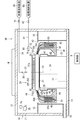
- FIG. 3 is a vertical sectional view of the processing unit 1.
- the processing unit 1 includes a spin chuck 20, which is an example of a substrate holding portion, a first nozzle 30, a second nozzle 60, a third nozzle 65, a fixed nozzle 80, and a processing cup 40. Includes camera 70.
- the chamber 10 includes a side wall 11 along the vertical direction, a ceiling wall 12 that closes the upper side of the space surrounded by the side wall 11, and a floor wall 13 that closes the lower side.
- the space surrounded by the side wall 11, the ceiling wall 12, and the floor wall 13 is the processing space.
- a part of the side wall 11 of the chamber 10 is provided with a carry-in / out entrance for the main transfer robot 103 to carry in / out the substrate W and a shutter for opening / closing the carry-in / out port (both are not shown).
- a fan filter unit (FFU) 14 for further purifying the air in the clean room in which the substrate processing apparatus 100 is installed and supplying it to the processing space in the chamber 10 is attached to the ceiling wall 12 of the chamber 10. .
- the fan filter unit 14 includes a fan and a filter (for example, a HEPA (High Efficiency Particulate Air) filter) for taking in the air in the clean room and sending it out into the chamber 10, and the clean air is brought down to the processing space in the chamber 10.
- a punching plate having a large number of blowout holes may be provided directly under the ceiling wall 12.
- the spin chuck 20 holds the substrate W in a horizontal posture (a posture in which the normal line is along the vertical direction).
- the spin chuck 20 includes a disk-shaped spin base 21 fixed in a horizontal posture to the upper end of a rotating shaft 24 extending in the vertical direction.
- a spin motor 22 for rotating the rotating shaft 24 is provided below the spin base 21, a spin motor 22 for rotating the rotating shaft 24 is provided.
- the spin motor 22 rotates the spin base 21 in a horizontal plane via the rotation shaft 24.
- a cylindrical cover member 23 is provided so as to surround the spin motor 22 and the rotation shaft 24.
- the outer diameter of the disk-shaped spin base 21 is slightly larger than the diameter of the circular substrate W held by the spin chuck 20. Therefore, the spin base 21 has an upper surface 21a facing the entire lower surface of the substrate W to be held.
- a plurality of (four in this embodiment) chuck pins 26 are erected on the peripheral edge of the upper surface 21a of the spin base 21.
- the plurality of chuck pins 26 are evenly spaced along the circumference corresponding to the peripheral edge of the circular substrate W (at 90 ° intervals for four chuck pins 26 as in the present embodiment). Have been placed.
- Each chuck pin 26 is provided so as to be driveable between a holding position in contact with the peripheral edge of the substrate W and an open position away from the peripheral edge of the substrate W.
- the plurality of chuck pins 26 are driven in conjunction with each other by a link mechanism (not shown) housed in the spin base 21.
- the spin chuck 20 can hold the substrate W above the spin base 21 in a horizontal posture close to the upper surface 21a (FIG. 3). (See), the holding of the substrate W can be released by stopping the plurality of chuck pins 26 at their respective open positions.
- the lower end of the cover member 23 covering the spin motor 22 is fixed to the floor wall 13 of the chamber 10, and the upper end reaches directly below the spin base 21.
- a flange-shaped member 25 is provided which projects outward from the cover member 23 substantially horizontally and further bends downward and extends.
- the first nozzle 30 is configured by attaching a discharge head 31 to the tip of the nozzle arm 32.
- the base end side of the nozzle arm 32 is fixedly connected to the nozzle base 33.
- the nozzle base 33 is made rotatable around an axis along the vertical direction by a motor (not shown). As the nozzle base 33 rotates, the first nozzle 30 moves in an arc shape in the space above the spin chuck 20 as shown by the arrow AR34 in FIG.
- FIG. 4 is a plan view schematically showing an example of the movement path of the first nozzle 30.
- the discharge head 31 of the first nozzle 30 moves along the circumferential direction around the nozzle base 33 by the rotation of the nozzle base 33.
- the first nozzle 30 can be stopped at an appropriate position. In the example of FIG. 4, the first nozzle 30 can be stopped at each of the central position P31, the peripheral position P32, and the standby position P33.
- the central position P31 is a position where the discharge head 31 faces the central portion of the substrate W held by the spin chuck 20 in the vertical direction.
- the peripheral edge position P32 is a position where the discharge head 31 faces the peripheral edge portion of the substrate W held by the spin chuck 20 in the vertical direction.
- the first nozzle 30 may discharge the processing liquid onto the upper surface of the rotating substrate W in a state where the first nozzle 30 is located at the peripheral edge position P32.
- the treatment liquid can be discharged only to the peripheral edge portion of the upper surface of the substrate W, and only the peripheral edge portion of the substrate W can be treated (so-called bevel processing).
- the first nozzle 30 can also discharge the processing liquid onto the upper surface of the rotating substrate W while swinging between the central position P31 and the peripheral position P32. Also in this case, the entire surface of the upper surface of the substrate W can be processed.
- the first nozzle 30 does not have to discharge the processing liquid at the peripheral position P32.
- the peripheral edge position P32 may be a relay position that temporarily stands by when the first nozzle 30 moves from the central position P31 to the standby position P33.
- the standby position P33 is a position where the discharge head 31 does not face the substrate W held by the spin chuck 20 in the vertical direction.
- the standby position P33 may be provided with a standby pod that accommodates the discharge head 31 of the first nozzle 30.
- the first nozzle 30 is connected to the processing liquid supply source 36 via the supply pipe 34.
- a valve 35 is provided in the supply pipe 34. The valve 35 opens and closes the flow path of the supply pipe 34. When the valve 35 opens, the processing liquid supply source 36 supplies the processing liquid to the first nozzle 30 through the supply pipe 34.
- the first nozzle 30 may be configured to be supplied with a plurality of types of treatment liquids (including at least pure water).
- the processing unit 1 of the present embodiment is further provided with a second nozzle 60 and a third nozzle 65 in addition to the first nozzle 30.
- the second nozzle 60 and the third nozzle 65 of the present embodiment have the same configuration as the first nozzle 30 described above. That is, the second nozzle 60 is configured by attaching the discharge head 61 to the tip of the nozzle arm 62.
- the second nozzle 60 moves in an arc shape in the space above the spin chuck 20 by the nozzle base 63 connected to the base end side of the nozzle arm 62, as shown by the arrow AR64.
- the relative positional relationship between the central position P61, the peripheral edge position P62, and the standby position P63 located on the movement path of the second nozzle 60 is the relative positional relationship between the central position P31, the peripheral edge position P32, and the standby position P33, respectively. The same is true.
- the third nozzle 65 is configured by attaching a discharge head 66 to the tip of the nozzle arm 67.
- the third nozzle 65 moves in an arc shape in the space above the spin chuck 20 by the nozzle base 68 connected to the base end side of the nozzle arm 67, as shown by the arrow AR69. It moves in an arc shape between the processing position and the standby position outside the processing cup 40.
- the relative positional relationship between the central position P66, the peripheral edge position P67, and the standby position P68 located on the movement path of the third nozzle 65 is the relative positional relationship between the central position P31, the peripheral edge position P32, and the standby position P33, respectively. The same is true.
- the third nozzle 65 may be able to move up and down.
- the third nozzle 65 moves up and down by a nozzle raising and lowering mechanism (not shown) built in the nozzle base 68.
- the third nozzle 65 can also be stopped at the central upper position P69 located vertically above the central position P66.
- at least one of the first nozzle 30 and the second nozzle 60 may be provided so as to be able to move up and down.
- Each of the second nozzle 60 and the third nozzle 65 is also connected to the processing liquid supply source (not shown) via the supply pipe (not shown) like the first nozzle 30.
- a valve is provided in each supply pipe, and the supply / stop of the processing liquid can be switched by opening and closing the valve.
- Each of the second nozzle 60 and the third nozzle 65 may be configured to be supplied with a plurality of types of treatment liquids containing at least pure water. Further, at least one of the first nozzle 30, the second nozzle 60 and the third nozzle 65 mixes a cleaning liquid such as pure water with a pressurized gas to generate droplets, and the droplets and gas are generated. It may be a two-fluid nozzle that injects a mixed fluid with the substrate W onto the substrate W. Further, the number of nozzles provided in the processing unit 1 is not limited to three, and may be one or more.
- the processing unit 1 is also provided with a fixed nozzle 80.
- the fixed nozzle 80 is located above the spin chuck 20 and radially outside the outer peripheral edge of the spin chuck 20.
- the fixed nozzle 80 is provided at a position facing the processing cup 40 described later in the vertical direction.
- the discharge port of the fixed nozzle 80 faces the substrate W side, and its opening axis is, for example, along the horizontal direction.
- the fixed nozzle 80 also discharges the processing liquid onto the upper surface of the substrate W held by the spin chuck 20.
- the treatment liquid discharged from the fixed nozzle 80 is, for example, landed on the central portion of the upper surface of the substrate W.
- the fixed nozzle 80 is connected to the processing liquid supply source 83 via the supply pipe 81.
- a valve 82 is provided in the supply pipe 81.
- the valve 82 opens and closes the flow path of the supply pipe 81.
- the processing liquid supply source 83 supplies the processing liquid (for example, pure water) to the fixed nozzle 80 through the supply pipe 81, and the processing liquid is discharged from the discharge port of the fixed nozzle 80.
- the processing cup 40 surrounding the spin chuck 20 includes an inner cup 41, an inner cup 42, and an outer cup 43 that can be raised and lowered independently of each other.
- the inner cup 41 has a shape that surrounds the spin chuck 20 and is substantially rotationally symmetric with respect to the rotation axis CX that passes through the center of the substrate W held by the spin chuck 20.
- the inner cup 41 includes a bottom portion 44 having an annular shape in a plan view, a cylindrical inner wall portion 45 rising upward from the inner peripheral edge of the bottom portion 44, a cylindrical outer wall portion 46 rising upward from the outer peripheral edge of the bottom portion 44, and an inner wall.
- the first guide portion 47 that rises from between the portion 45 and the outer wall portion 46 and extends diagonally upward toward the center side (direction approaching the rotation axis CX of the substrate W held by the spin chuck 20) while drawing a smooth arc at the upper end portion.
- the cylindrical inner wall portion 48 rising upward from between the first guide portion 47 and the outer wall portion 46 are integrally included.
- the inner wall portion 45 is formed to have a length that allows the inner cup 41 to be accommodated with an appropriate gap between the cover member 23 and the flange-shaped member 25 in a state where the inner cup 41 is most raised.
- the middle wall portion 48 is housed in a state where the inner cup 41 and the middle cup 42 are closest to each other, while maintaining an appropriate gap between the second guide portion 52 described later of the middle cup 42 and the treatment liquid separation wall 53. It is formed to such a length.
- the first guide portion 47 has an upper end portion 47b extending diagonally upward on the center side (direction approaching the rotation axis CX of the substrate W) while drawing a smooth arc. Further, between the inner wall portion 45 and the first guide portion 47, there is a waste groove 49 for collecting and disposing of the used treatment liquid. Between the first guide portion 47 and the middle wall portion 48, there is an annular inner recovery groove 50 for collecting and collecting the used treatment liquid. Further, between the inner wall portion 48 and the outer wall portion 46, there is an annular outer recovery groove 51 for collecting and collecting a treatment liquid different from the inner recovery groove 50.
- the waste groove 49 is connected to an exhaust liquid mechanism (not shown) for discharging the treatment liquid collected in the waste groove 49 and forcibly exhausting the inside of the waste groove 49.
- an exhaust liquid mechanism (not shown) for discharging the treatment liquid collected in the waste groove 49 and forcibly exhausting the inside of the waste groove 49.
- four exhaust gas mechanisms are provided at equal intervals along the circumferential direction of the waste groove 49.
- the inner recovery groove 50 and the outer recovery groove 51 have a recovery mechanism for collecting the treatment liquid collected in the inner recovery groove 50 and the outer recovery groove 51 in a recovery tank provided outside the treatment unit 1. Both are connected (not shown).
- the bottoms of the inner recovery groove 50 and the outer recovery groove 51 are inclined by a slight angle with respect to the horizontal direction, and the recovery mechanism is connected to the lowest position thereof. As a result, the treatment liquid that has flowed into the inner recovery groove 50 and the outer recovery groove 51 is smoothly recovered.
- the middle cup 42 has a shape that surrounds the spin chuck 20 and is substantially rotationally symmetric with respect to the rotation axis CX that passes through the center of the substrate W held by the spin chuck 20.
- the middle cup 42 integrally includes a second guide portion 52 and a cylindrical processing liquid separation wall 53 connected to the second guide portion 52.
- the second guide portion 52 draws a smooth arc from the lower end portion 52a forming a coaxial cylindrical shape with the lower end portion of the first guide portion 47 and the upper end of the lower end portion 52a on the outside of the first guide portion 47 of the inner cup 41. It has an upper end portion 52b extending diagonally upward on the center side (direction approaching the rotation axis CX of the substrate W), and a folded portion 52c formed by folding the tip end portion of the upper end portion 52b downward.
- the lower end portion 52a is housed in the inner recovery groove 50 with an appropriate gap between the first guide portion 47 and the middle wall portion 48 in a state where the inner cup 41 and the middle cup 42 are closest to each other.
- the upper end portion 52b is provided so as to overlap the upper end portion 47b of the first guide portion 47 of the inner cup 41 in the vertical direction, and the first guide portion 47 is in a state where the inner cup 41 and the middle cup 42 are closest to each other. Close to the upper end 47b of the. Further, in the folded portion 52c formed by folding the tip of the upper end portion 52b downward, the folded portion 52c is the tip of the upper end portion 47b of the first guide portion 47 in a state where the inner cup 41 and the middle cup 42 are closest to each other. The length is such that it overlaps horizontally.
- the upper end portion 52b of the second guide portion 52 is formed so that the wall thickness becomes thicker toward the lower side, and the treatment liquid separation wall 53 is provided so as to extend downward from the lower end outer peripheral edge portion of the upper end portion 52b. It has a cylindrical shape.
- the treatment liquid separation wall 53 is housed in the outer recovery groove 51 with an appropriate gap between the inner wall portion 48 and the outer cup 43 in a state where the inner cup 41 and the middle cup 42 are closest to each other.
- the outer cup 43 surrounds the spin chuck 20 on the outside of the second guide portion 52 of the middle cup 42, and is substantially rotationally symmetric with respect to the rotation axis CX passing through the center of the substrate W held by the spin chuck 20. It has a shape.
- the outer cup 43 has a function as a third guide portion.
- the outer cup 43 has a lower end portion 43a coaxially cylindrical with the lower end portion 52a of the second guide portion 52, and a center side (direction approaching the rotation axis CX of the substrate W) while drawing a smooth arc from the upper end of the lower end portion 43a. It has an upper end portion 43b extending diagonally upward and a folded portion 43c formed by folding the tip end portion of the upper end portion 43b downward.
- the lower end portion 43a has an outer recovery groove with an appropriate gap between the treatment liquid separation wall 53 of the middle cup 42 and the outer wall portion 46 of the inner cup 41 in a state where the inner cup 41 and the outer cup 43 are closest to each other. It is housed in 51. Further, the upper end portion 43b is provided so as to overlap the second guide portion 52 of the middle cup 42 in the vertical direction, and the upper end portion 52b of the second guide portion 52 is in a state where the middle cup 42 and the outer cup 43 are closest to each other. Close to each other with a very small distance.
- the folded-back portion 43c and the folded-back portion 52c of the second guide portion 52 are in a state where the middle cup 42 and the outer cup 43 are closest to each other. It is formed so as to overlap in the horizontal direction.
- the inner cup 41, the middle cup 42 and the outer cup 43 can be raised and lowered independently of each other. That is, each of the inner cup 41, the middle cup 42, and the outer cup 43 is individually provided with a cup elevating mechanism (not shown), whereby the inner cup 41, the inner cup 42, and the outer cup 43 are individually and independently raised and lowered.
- a cup elevating mechanism various known mechanisms such as a ball screw mechanism and an air cylinder can be adopted.
- the partition plate 15 is provided so as to partition the inner space of the chamber 10 up and down around the processing cup 40.
- the partition plate 15 may be a single plate-shaped member surrounding the processing cup 40, or may be a combination of a plurality of plate-shaped members. Further, the partition plate 15 may be formed with a through hole or a notch penetrating in the thickness direction.
- the nozzle base 33 of the first nozzle 30 and the nozzle base 63 of the second nozzle 60 may be formed. And a through hole for passing a support shaft for supporting the nozzle base 68 of the third nozzle 65 is formed.
- the outer peripheral end of the partition plate 15 is connected to the side wall 11 of the chamber 10. Further, the edge portion of the partition plate 15 surrounding the processing cup 40 is formed so as to have a circular shape having a diameter larger than the outer diameter of the outer cup 43. Therefore, the partition plate 15 does not hinder the raising and lowering of the outer cup 43.
- an exhaust duct 18 is provided in the vicinity of the floor wall 13 which is a part of the side wall 11 of the chamber 10.
- the exhaust duct 18 is communicated with an exhaust mechanism (not shown).
- the air that has passed between the processing cup 40 and the partition plate 15 is discharged from the exhaust duct 18 to the outside of the device.
- the camera 70 is installed in the chamber 10 above the partition plate 15.
- the camera 70 includes, for example, a CCD (Charge Coupled Device), which is one of solid-state image pickup elements, and an optical system such as a lens.
- the camera 70 is provided to monitor various monitoring targets in the chamber 10, which will be described later. Specific examples of monitoring targets will be described in detail later.
- the camera 70 is arranged at a position that includes various monitoring targets in the imaging field of view.
- the camera 70 captures the imaging field of view at each frame rate, acquires captured image data, and sequentially outputs the acquired captured image data to the control unit 9.
- the illumination unit 71 is provided in the chamber 10 at a position above the partition plate 15.
- the control unit 9 may control the illumination unit 71 so that the illumination unit 71 irradiates light when the camera 70 performs imaging.
- the hardware configuration of the control unit 9 provided in the board processing device 100 is the same as that of a general computer. That is, the control unit 9 stores various information, a processing unit such as a CPU that performs various arithmetic processes, a temporary storage medium such as a ROM (ReaOnlyMemory) that is a read-only memory for storing a basic program, and various information. It includes a RAM (Random Access Memory), which is a readable and writable memory, and a non-temporary storage medium, such as a magnetic disk for storing control software or data.
- a processing unit such as a CPU that performs various arithmetic processes
- a temporary storage medium such as a ROM (ReaOnlyMemory) that is a read-only memory for storing a basic program
- ROM Read OnlyMemory
- control unit 9 When the CPU of the control unit 9 executes a predetermined processing program, each operation mechanism of the board processing device 100 is controlled by the control unit 9, and the processing in the board processing device 100 proceeds.
- the control unit 9 may be realized by a dedicated hardware circuit that does not require software to realize the function.
- FIG. 5 is a functional block diagram schematically showing an example of the internal configuration of the control unit 9.
- the control unit 9 includes a monitoring processing unit 91, a condition setting unit 92, and a processing control unit 93.
- the processing control unit 93 controls each configuration in the chamber 10. Specifically, the processing control unit 93 controls various valves such as the spin motor 22, valves 35 and 82, the motors of the nozzle bases 33, 63 and 68, the nozzle elevating mechanism, the cup elevating mechanism and the fan filter unit 14. .. When the processing control unit 93 controls these configurations according to a predetermined procedure, the processing unit 1 can perform processing on the substrate W. An example of a specific flow of processing for the substrate W will be described in detail later.
- the monitoring processing unit 91 performs monitoring processing based on the captured image data acquired by the camera 70 taking an image of the inside of the chamber 10. As a result, the monitoring processing unit 91 can monitor various monitoring targets in the chamber 10. Specific examples of the monitoring process will be described in detail later.
- the condition setting unit 92 identifies the monitoring target to be monitored and changes the imaging conditions of the camera 70 according to the monitoring target. Then, the condition setting unit 92 notifies the camera 70 of the imaging condition. Imaging conditions include, for example, at least one of resolution, frame rate and field of view. The camera 70 acquires the captured image data under the imaging conditions notified from the condition setting unit 92, and outputs the captured image data to the control unit 9. A specific example of the imaging conditions according to the monitoring target will be described in detail later.
- FIG. 6 is a flowchart showing an example of the flow of substrate processing.
- the main transfer robot 103 carries the unprocessed substrate W into the processing unit 1 (step S1: carry-in step).
- the spin chuck 20 holds the substrate W in a horizontal posture (step S2: holding step).
- the plurality of chuck pins 26 move to their respective contact positions, so that the plurality of chuck pins 26 hold the substrate W.
- step S3 rotation step
- step S4 cup raising step
- step S5 treatment liquid step
- the cup elevating mechanism appropriately switches the cup to be raised according to the type of the processing liquid supplied to the substrate W, but this point is the essence of the present embodiment. Since it is different from the above, the description thereof will be omitted below.
- FIG. 7 is a table showing an example of a specific procedure of the treatment liquid step (step S5).
- the treatment liquid process is defined by the steps ST1 to ST12.
- the table shows the time required for each step, the flow rate (discharge flow rate) of the processing liquid discharged from the first nozzle 30, the second nozzle 60, the third nozzle 65, and the fixed nozzle 80, and the first nozzle 30, the second nozzle 30.
- the positions of the nozzle 60 and the third nozzle 65 are shown.
- FIG. 7 also shows examples of monitoring processes and imaging conditions that can be executed in each step, which will be described in detail later.
- step ST1 the discharge flow rate of the processing liquid from the first nozzle 30, the second nozzle 60, the third nozzle 65, and the fixed nozzle 80 is zero over the required time t1, and the first nozzle 30 , The second nozzle 60 and the third nozzle 65 are stopped at the standby positions P33, P63, and P68, respectively.
- the required time t1 may be, for example, zero. In this case, step ST1 only shows the initial state.
- the nozzle base 33 moves the first nozzle 30 from the standby position P33 to the central position P31 in the required time t2.
- the required time t2 is, for example, about several seconds.
- the first nozzle 30 discharges the processing liquid onto the upper surface of the substrate W at the flow rate F30 in the required time t3.
- the treatment liquid that has landed on the upper surface of the substrate W receives centrifugal force due to the rotation of the substrate W, spreads on the upper surface of the substrate W, and scatters from the peripheral edge of the substrate W.
- the processing liquid scattered from the peripheral edge of the substrate W is received by the processing cup 40 and collected.
- the required time t3 is, for example, about several tens of seconds, and the flow rate F30 is, for example, about several thousand cc / min.
- the fixed nozzle 80 discharges the treatment liquid (for example, a rinse liquid) at the flow rate F80, and the nozzle base 33 moves the first nozzle 30 from the central position P31 to the peripheral position P32. ..
- the treatment liquid from the fixed nozzle 80 lands on the central portion of the upper surface of the substrate W, receives centrifugal force, spreads on the upper surface of the substrate W, and scatters from the peripheral edge of the substrate W.
- the processing liquid scattered from the peripheral edge of the substrate W is received by the processing cup 40 and collected.
- the required time t4 is, for example, about several tens of seconds
- the flow rate F80 is, for example, about several thousand cc / min.
- the fixed nozzle 80 continuously discharges the treatment liquid (for example, a rinse liquid) at the flow rate F80, while the nozzle base 33 moves the first nozzle 30 from the peripheral position P32 to the standby position P33 in the required time t5. Move it.
- the required time t5 is, for example, about several seconds.
- the fixed nozzle 80 continuously discharges the treatment liquid (for example, a rinse liquid) at the flow rate F80, while the nozzle base 63 moves the second nozzle 60 from the standby position P63 to the peripheral position P62 in the required time t6. Move it.
- the required time t6 is, for example, about several seconds.
- the fixed nozzle 80 discharges the processing liquid from the process ST4 to the process ST6.
- the treatment liquid discharged by the fixed nozzle 80 is a rinse liquid
- the treatment liquid remaining on the upper surface of the substrate W at the end of step ST3 can be replaced with the rinse liquid.
- the nozzle base 63 moves the second nozzle 60 from the peripheral position P62 to the central position P61, and the second nozzle 60 discharges the treatment liquid onto the upper surface of the substrate W at the flow rate F60. ..
- the required time t7 is, for example, about several tens of seconds, and the flow rate F60 is, for example, about several thousand cc / min.
- the upper surface of the substrate W can be processed.
- the nozzle base 63 moves the second nozzle 60 from the central position P61 to the standby position P63 in the required time t8.
- the required time t8 is, for example, about several seconds.
- the nozzle base 68 moves the third nozzle 65 from the standby position P68 to the center upper position P69 in the required time t9.
- the required time t9 is, for example, about several seconds.
- the third nozzle 65 discharges the treatment liquid onto the upper surface of the substrate W at a flow rate F65 at the required time t10.
- the required time t10 is, for example, about several tens of seconds, and the flow rate F65 is, for example, several thousand cc / min.
- the treatment liquid discharged by the third nozzle 65 is a rinse liquid, the treatment liquid remaining on the upper surface of the substrate W at the end of the step ST7 can be replaced with the rinse liquid.
- the nozzle base 63 lowers the third nozzle 65 from the central upper position P69 to the central position P65 in the required time t11.
- the required time t11 is, for example, about several tens of seconds.
- the nozzle base 63 moves the third nozzle 65 from the central position P65 to the standby position P68 in the required time t12.
- the required time t12 is, for example, about several seconds.
- step S6 drying step
- the spin motor 22 increases the rotation speed of the substrate W to dry the substrate W (so-called spin dry).
- step S7 cup lowering step
- step S8 holding release step
- the holding is released by moving the plurality of chuck pins 26 to their respective open positions.
- step S9 carry-out step
- the processing for the substrate W is performed.
- the monitoring processing unit 91 monitors the inside of the chamber 10 using the camera 70, and determines whether or not the processing for the substrate W is proceeding appropriately. As can be understood from the following description, the monitoring target monitored by the monitoring processing unit 91 changes sequentially according to the progress of the processing. Hereinafter, an example of the monitoring target in the chamber 10 will be described.
- the first nozzle 30, the second nozzle 60, and the third nozzle 65 move appropriately.
- the first nozzle 30 moves from the standby position P33 to the central position P31 in the step ST2.
- the first nozzle 30 may shift from the central position P31 and stop due to a motor abnormality of the nozzle base 33 or the like. In this case, the process in step ST3 may be improperly terminated.
- the position of the nozzle may be adopted as a monitoring target in the process (period) in which the nozzle moves.
- the process of performing the position monitoring process for monitoring the position of the nozzle is schematically shown by hatching with diagonal lines.
- a specific example of the position monitoring process will be described.
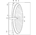
- FIG. 8 is a diagram schematically showing an example of captured image data acquired in the process of performing position monitoring processing.
- FIG. 8 shows an example of captured image data acquired in step ST2.
- the captured image data of FIG. 8 includes a discharge head 31 of the first nozzle 30 that stops at the central position P31. That is, FIG. 8 shows the captured image data acquired after the first nozzle 30 has moved from the standby position P33 to the central position P31 in the step ST2.
- the captured image data includes a processing cup 40 located at an upper position, a substrate W located inside the opening of the processing cup 40, and a fixed nozzle 80.
- the monitoring processing unit 91 analyzes the captured image data acquired in the process ST2 and detects the position of the first nozzle 30. For example, the monitoring processing unit 91 performs pattern matching between the reference image data RI1 including the first nozzle 30 (specifically, the ejection head 31) stored in the storage medium in advance and the captured image data in the captured image data. The position of the first nozzle 30 of the above is specified.
- the reference image data RI1 is schematically shown by a virtual line overlaid on the captured image data.
- the monitoring processing unit 91 determines whether or not the position of the detected first nozzle 30 is appropriate. For example, the monitoring processing unit 91 determines whether or not the difference between the position of the first nozzle 30 and the preset central position P31 is equal to or less than a predetermined nozzle position allowable value. The monitoring processing unit 91 determines that the first nozzle 30 is located at the central position P31 when the difference is equal to or less than the nozzle position allowable value. On the other hand, the monitoring processing unit 91 determines that the first nozzle 30 is not located at the central position P31 when the difference is larger than the nozzle position allowable value. That is, the monitoring processing unit 91 determines that the nozzle position abnormality has occurred.
- the monitoring processing unit 91 may notify a notification unit (for example, a display or a speaker) (not shown) of the abnormality. Further, the control unit 9 may stop the operation of the processing unit 1 to interrupt the processing for the substrate W. Since this point is the same in the following various monitoring processes, repeated explanations will be avoided below.
- a notification unit for example, a display or a speaker
- the monitoring processing unit 91 does not need to determine the suitability of the position while the first nozzle 30 is moving. Therefore, the monitoring processing unit 91 may determine that the first nozzle 30 has stopped when the position of the first nozzle 30 in a plurality of consecutive captured image data becomes constant. Then, the monitoring processing unit 91 may determine whether or not the difference between the position of the first nozzle 30 after stopping and the central position P31 is equal to or less than the nozzle position allowable value. That is, the monitoring processing unit 91 may determine whether or not the position of the first nozzle 30 is appropriate after the position of the first nozzle 30 is stabilized.
- the first nozzle 30 stops at the central position P31.
- the monitoring processing unit 91 does not need to perform the position monitoring processing in the step ST3.
- the monitoring processing unit 91 does not perform the position monitoring processing in the process ST3. According to this, it is possible to reduce the execution of unnecessary position monitoring processing, and it is possible to reduce the processing load of the monitoring processing unit 91.
- the monitoring processing unit 91 may also perform the position monitoring processing in the process ST4. Specifically, the monitoring processing unit 91 detects the position of the first nozzle 30 after stopping based on the captured image data, and determines whether or not the first nozzle 30 is appropriately stopped at the peripheral position P32. May be good. This suitability determination can also be performed in the same manner as described above.
- the monitoring processing unit 91 does not perform the position monitoring processing in the process ST5. That is, the monitoring processing unit 91 does not monitor the position of the first nozzle 30 with respect to the standby position P33. This is because even if the first nozzle 30 deviates from the standby position P33 and stops, the influence on the processing of the substrate W is small. Of course, the monitoring processing unit 91 may also perform position monitoring processing on the standby position P33.
- the monitoring processing unit 91 may also perform position monitoring processing on the second nozzle 60 and the third nozzle 65 at least in a process in which the positions change.
- the monitoring processing unit 91 since the second nozzle 60 moves in the process ST6 and the process ST7, the monitoring processing unit 91 performs a position monitoring process for monitoring the position of the second nozzle 60 in the process ST6 and the process ST7. Further, in the example of FIG. 7, since the third nozzle 65 moves in the process ST9 and the process ST11, the monitoring processing unit 91 performs a position monitoring process for monitoring the position of the third nozzle 65 in the process ST9 and the process ST11.
- the monitoring processing unit 91 performs position monitoring processing. No. Of course, the position monitoring process may be performed in these steps as well.
- the first nozzle 30, the second nozzle 60, the third nozzle 65, and the fixed nozzle 80 appropriately discharge the processing liquid.
- the first nozzle 30 discharges the processing liquid onto the upper surface of the substrate W in the required time t3 of the step ST3.
- the substrate W can be processed by appropriately discharging the processing liquid from the first nozzle 30.
- the state of the treatment liquid may be adopted as a monitoring target in the process in which each nozzle discharges the treatment liquid.
- the process of performing the treatment liquid monitoring process regarding the treatment liquid is schematically shown by hatching of sand.
- a specific example of the treatment liquid monitoring process will be described.
- ⁇ Discharge time> For example, if the discharge time at which the first nozzle 30 actually discharges the processing liquid deviates from the specified time in the process ST3, the processing in the process ST3 may be improperly terminated. Specifically, if the ejection time is too short, the processing for the substrate W is insufficient, and if the ejection time is too long, the processing for the substrate W becomes excessive.
- the discharge start timing and discharge stop timing of the treatment liquid, and eventually the discharge time may be adopted.
- the discharge time monitoring process for monitoring the discharge time of the processing liquid will be described.
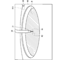
- FIG. 9 is a diagram schematically showing an example of captured image data acquired in the process of performing the discharge time monitoring process.
- FIG. 9 shows an example of captured image data acquired in step ST3.
- the captured image data of FIG. 9 includes the first nozzle 30 that discharges the processing liquid. That is, FIG. 9 shows the captured image data acquired after the first nozzle 30 starts discharging the processing liquid in the step ST3.
- the camera 70 sequentially acquires captured image data (for example, FIG. 8) including the first nozzle 30 that does not discharge the processing liquid.
- the camera 70 sequentially acquires captured image data (for example, FIG. 9) including the first nozzle 30 that ejects the processing liquid. Therefore, if it is possible to specify whether or not the first nozzle 30 is discharging the processing liquid for each of the captured image data acquired sequentially, the first nozzle 30 starts the processing liquid based on the specific result. The timing can be specified.
- the monitoring processing unit 91 determines whether or not the first nozzle 30 discharges the processing liquid for each captured image data.
- the ejection determination region R1 is set in the captured image data.
- the discharge determination region R1 includes a region extending in the discharge direction from the tip of the first nozzle 30 (that is, the tip of the discharge head 31).
- the discharge determination region R1 has, for example, a rectangular shape extending from the tip of the first nozzle 30 in the discharge direction (here, the lower side).
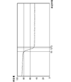
- the pixel values in the ejection determination region R1 are when the first nozzle 30 ejects the processing liquid and when the first nozzle 30 does not eject the processing liquid. Is different.
- the sum of the pixel values in the ejection determination region R1 when the first nozzle 30 is ejecting the processing liquid is the pixel value in the ejection determination region R1 when the first nozzle 30 is not ejecting the processing liquid. It will be larger than the sum of.
- the monitoring processing unit 91 determines whether or not the first nozzle 30 is discharging the processing liquid for each captured image data acquired in the step ST3 based on the pixel value of the discharge determination region R1. As a specific example, the monitoring processing unit 91 determines whether or not the sum of the pixel values in the ejection determination region R1 is equal to or greater than a predetermined ejection reference value, and when the sum is equal to or greater than the ejection reference value, the first is 1 It is determined that the nozzle 30 is discharging the processing liquid. Further, the monitoring processing unit 91 determines that the first nozzle 30 is not discharging the processing liquid when the total is less than the discharge reference value.
- the determination of the presence or absence of ejection of the processing liquid based on the pixel value in the ejection determination region R1 is not limited to this, and various methods can be adopted.
- the dispersion of the pixel values in the ejection determination region R1 when the first nozzle 30 is ejecting the processing liquid is larger than the dispersion when the first nozzle 30 is not ejecting the processing liquid. Therefore, the monitoring processing unit 91 may calculate the dispersion and determine whether or not the processing liquid is discharged based on the magnitude of the dispersion. It is also possible to use the standard deviation instead of the variance.
- the monitoring processing unit 91 is based on, for example, the acquisition timing of the captured image data in which the first nozzle 30 does not discharge the processing liquid and the acquisition timing of the captured image data in which the first nozzle 30 discharges the processing liquid. Identify the start timing.
- the monitoring processing unit 91 can also specify the end timing at which the first nozzle 30 ends the discharge of the processing liquid.
- the monitoring processing unit 91 calculates the difference between the discharge stop timing and the discharge start timing as the discharge time. Next, the monitoring processing unit 91 determines whether or not the discharge time is appropriate. For example, the monitoring processing unit 91 determines whether or not the difference between the discharge time and the specified time is equal to or less than a predetermined time allowable value. When the difference is equal to or less than the time allowable value, the monitoring processing unit 91 determines that the discharge time is appropriate. Further, the monitoring processing unit 91 determines that the discharge time is inappropriate when the difference is larger than the time allowable value. That is, the monitoring processing unit 91 determines that the discharge time abnormality has occurred.
- the discharge time monitoring process may be performed in each step of discharging the treatment liquid.
- the discharge time monitoring process for the second nozzle 60 and the third nozzle 65 is the same as that for the first nozzle 30.
- the fixed nozzle 80 discharges the processing liquid from the process ST4 to the process ST6.
- the monitoring processing unit 91 performs the processing liquid monitoring processing in the process ST4, but this processing liquid monitoring processing includes the liquid splash monitoring processing described later, and the discharge time monitoring processing for the fixed nozzle 80. Does not contain. Further, in the example of FIG. 7, the monitoring processing unit 91 does not perform the processing liquid monitoring processing in the process ST5 and the process ST6. However, the present invention is not limited to this, and the monitoring processing unit 91 may perform the ejection time monitoring processing for the fixed nozzle 80 in the steps ST4 to ST6.
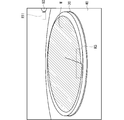
- FIG. 10 is a diagram schematically showing an example of captured image data acquired in steps ST4 to ST6.
- the captured image data of FIG. 10 includes a fixed nozzle 80 for discharging the processing liquid. That is, FIG. 10 shows the captured image data acquired after the fixed nozzle 80 ejects the processing liquid.
- a discharge determination region R11 for determining the presence / absence of discharge of the processing liquid from the fixed nozzle 80 is set. Since the fixed nozzle 80 discharges the processing liquid along the horizontal direction, the discharge determination region R11 has, for example, a rectangular shape extending laterally from the tip of the fixed nozzle 80.
- the discharge time monitoring process using the discharge determination area R11 is the same as the discharge time monitoring process using the discharge determination area R1.
- the processing liquid may splash on the upper surface of the substrate W due to various factors such as, for example, the first nozzle 30 discharging the processing liquid onto the upper surface of the substrate W at a flow rate larger than the flow rate F30 (so-called liquid splash). ).
- the processing unit 1 cannot properly process the substrate W.
- the presence or absence of liquid splashing of the treatment liquid may be adopted as a monitoring target in the process in which each nozzle discharges the treatment liquid.
- a specific example of the liquid splash monitoring process for monitoring the presence or absence of liquid splash will be described.
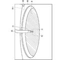
- FIG. 11 is a diagram schematically showing an example of captured image data acquired in step ST3.
- liquid splashes occur.
- the treatment liquid flowing down from the first nozzle 30 bounces off the upper surface of the substrate W, so that the treatment liquid bounces in a crown shape surrounding the liquid landing position.
- the liquid splash determination region R2 is set in the captured image data.
- the liquid splash determination region R2 may be set to a region including a part of the processing liquid splashing from the upper surface of the substrate W. Since the treatment liquid bounces around the liquid landing position, the liquid splash determination region R2 may be set next to, for example, the discharge determination region R1.
- the liquid splash determination region R2 is separated from the discharge determination region R1, and is located, for example, on the left side of the discharge determination region R1.
- the liquid splash determination region R2 has a rectangular shape.
- the pixel value in the liquid splash determination region R2 differs between when liquid splash does not occur (for example, FIG. 9) and when liquid splash occurs (for example, FIG. 11). For example, when light hits the treatment liquid splashed from the upper surface of the substrate W, the light is diffusely reflected. Therefore, the total of the pixel values of the liquid splash determination region R2 when the liquid splashes is that the liquid splashes do not occur. When the liquid splashes, it becomes larger than the sum of the pixel values in the determination region R2.
- the monitoring processing unit 91 determines whether or not liquid splashing has occurred for each captured image data acquired in step ST3, based on the pixel values in the liquid splash determination region R2. As a specific example, the monitoring processing unit 91 determines whether or not the sum of the pixel values in the liquid splash determination region R2 is equal to or greater than a predetermined liquid splash reference value, and the sum is the liquid splash reference value. When it is less than, it is judged that the liquid is not splashed. On the other hand, the monitoring processing unit 91 determines that liquid splashing has occurred when the total sum is equal to or higher than the liquid splashing reference value. That is, the monitoring processing unit 91 determines that a liquid splash abnormality has occurred.
- the determination of the presence or absence of liquid splash based on the pixel value in the liquid splash determination region R2 is not limited to this, and various methods can be adopted. For example, when light hits the treatment liquid splashed from the upper surface of the substrate W, the light is diffusely reflected. Therefore, when the liquid splashes, the dispersion of the pixel values in the liquid splash determination region R2 causes the liquid splashes. Greater than the variance when not. Therefore, the monitoring processing unit 91 may calculate the dispersion and determine the presence or absence of liquid splash based on the magnitude of the dispersion. It is also possible to use the standard deviation instead of the variance.
- the monitoring processing unit 91 performs a liquid splash monitoring process in the process of discharging the treatment liquid by each nozzle. Since the fixed nozzle 80 discharges the treatment liquid from its tip along the horizontal direction, the liquid splash tends to occur on the side opposite to the fixed nozzle 80 with respect to the liquid landing position. In the example of FIG. 11, since the liquid splash determination region R2 is located on the side opposite to the fixed nozzle 80 with respect to the liquid landing position, it is possible to detect the liquid splash accompanying the discharge of the processing liquid from the fixed nozzle 80. Can also be used.
- liquid splash monitoring process is performed in the process ST4 for the fixed nozzle 80
- the liquid splash monitoring process may also be performed in the process ST5 and the process ST6.
- the presence or absence of dripping may be adopted as a monitoring target in the process in which each nozzle discharges the treatment liquid.
- a specific example of the dripping monitoring process for monitoring the presence or absence of dripping will be described.
- FIG. 12 is a diagram schematically showing an example of captured image data acquired in step ST3.
- FIG. 12 shows captured image data acquired immediately after the first nozzle 30 stops discharging the processing liquid, and in the example of FIG. 12, dripping has occurred.
- the pixel values in the ejection determination region R1 are set when the first nozzle 30 is not ejecting the processing liquid (FIG. 8) and when the first nozzle 30 is ejected.
- FIG. 9 There is a difference between when the treatment liquid is being discharged (FIG. 9) and when dripping occurs (FIG. 12).
- the sum of the pixel values in the ejection determination region R1 when the dripping occurs is smaller than the sum of the pixel values in the ejection determination region R1 when the first nozzle 30 is ejecting the processing liquid. It is larger than the sum of the pixel values in the ejection determination region R1 when the first nozzle 30 is not ejecting the processing liquid.
- the monitoring processing unit 91 determines whether or not the dropout has occurred for each captured image data acquired in the step ST3 based on the pixel value of the ejection determination region R1.
- the monitoring processing unit 91 determines that the first nozzle 30 is discharging the processing liquid when the total sum of the pixel values in the discharge determination region R1 is equal to or greater than a predetermined first reference value.
- the sum of the pixel values in the ejection determination region R1 is less than the first reference value and equal to or more than the predetermined second reference value, it is determined that a dripping abnormality has occurred, and the sum of the pixel values in the ejection determination region R1 is summed.
- the second reference value it may be determined that the first nozzle 30 is not discharging the processing liquid.
- the determination of the presence or absence of dripping based on the pixel value in the ejection determination region R1 is not limited to this, and various methods can be adopted.
- the presence or absence of dripping may be determined based on the variance or standard deviation in the discharge determination region R1.
- each valve may open slightly due to an abnormality in each valve. In this case, the discharge of the processing liquid cannot be stopped properly, and the processing liquid continues to flow out from the nozzle (so-called outflow). In this case, since the processing liquid continues to be discharged to the upper surface of the substrate W, a processing defect may occur.
- the presence or absence of outflow may be adopted as a monitoring target in the process in which each nozzle discharges the treatment liquid.
- the outflow monitoring process for monitoring the presence / absence of outflow will be described.
- the outflow is an abnormality in which the processing liquid is discharged from the nozzle with the closing signal output to the valve. Since the valve is controlled by the processing control unit 93, the monitoring processing unit 91 can recognize whether or not a closing signal is output to the valve. Further, the monitoring processing unit 91 can determine whether or not the processing liquid is discharged from the nozzles based on the captured image data as described in the discharge time monitoring processing.
- the monitoring processing unit 91 determines that the first nozzle 30 is discharging the processing liquid even though the processing control unit 93 outputs a closing signal to the valve 35, the first nozzle 30 It is judged that an abnormal flow has occurred. The same applies to the second nozzle 60 and the third nozzle 65.
- the monitoring target changes according to each step defining the treatment liquid step (step S5).
- the monitoring target is, for example, the position of the first nozzle 30 during the execution period of the process ST2, and the state (shape) change (shape) of the processing liquid discharged from the first nozzle 30 during the execution period of the process ST3.
- the state change of the processing liquid is not the monitoring target and the nozzle position is the monitoring target.
- the nozzle position is not the monitoring target and the treatment liquid is discharged. The status is monitored. Further, both the position of the nozzle and the change of state of the processing liquid may be monitored, such as the execution period of the step ST7.
- the condition setting unit 92 sets the imaging conditions according to the monitoring target in each execution period.
- the imaging conditions in the execution period for example, step ST2 in which the nozzle position is monitored and the imaging in the execution period (for example, step ST3) in which the state change of the processing liquid is monitored.
- the conditions will be described, and then the imaging conditions during the execution period (for example, step ST7) in which both the nozzle position and the state change of the processing liquid are monitored will be described.
- ⁇ Nozzle position monitoring process> The higher the resolution of the captured image data, the finer and clearer the shape of each nozzle in the captured image data. Therefore, if the camera 70 acquires the captured image data for position monitoring processing at high resolution, the monitoring processing unit 91 can detect the position of the nozzle with higher accuracy based on the captured image data.
- condition setting unit 92 sets the resolution to a high resolution as an imaging condition when the camera 70 acquires the captured image data for the position monitoring process. Specifically, the condition setting unit 92 sets the resolution to a higher resolution as the imaging conditions in the process ST2, the process ST4, the process ST6, the process ST7, the process ST9, and the process ST11 (see also FIG. 7).
- the frame rate of the captured image data is low, problems are unlikely to occur in the position monitoring process. That is, since the nozzle stop position is monitored in the position monitoring process, there is no problem in the position monitoring process even if the frame rate is low. Further, even when monitoring the change of the nozzle position over time, the frame rate may be lowered if it is not necessary to detect the nozzle position at short time intervals.
- the condition setting unit 92 sets the resolution to a high resolution and the frame rate to a low frame rate as the imaging conditions in the execution period of the process ST2, the process ST6, the process ST9, and the process ST11.
- the condition setting unit 92 sets the resolution to a high resolution and the frame rate to a low frame rate as the imaging conditions of the captured image data not used in the processing liquid monitoring process but used in the position monitoring process.
- the condition setting unit 92 sets the resolution to high resolution and the frame rate to low frame rate as the imaging condition in the period in which the nozzle position is monitored without monitoring the state change of the processing liquid. do.
- the condition setting unit 92 notifies the camera 70 of the set imaging conditions.
- the camera 70 acquires captured image data according to the received imaging conditions. That is, the camera 70 acquires captured image data at a high resolution and a low frame rate in the process ST2, the process ST6, the process ST9, and the process ST11.
- the resolution can be changed, for example, by the binning function of the camera 70.
- the binning function is a function of changing the number of light receiving elements read out as one pixel among a plurality of light receiving elements of the camera 70. For example, consider the case where the light receiving surface of the camera 70 is composed of vertical Nx (for example, 2448) light receiving elements ⁇ horizontal Ny (for example, 2048) light receiving elements. By reading the data of each light receiving element as one pixel, the camera 70 can acquire the captured image data having Nx vertical ⁇ Ny horizontal pixels.
- the camera 70 reads out the data of a total of four light receiving elements, for example, 2 vertical ⁇ 2 horizontal, as one pixel, so that Nx / 2 (for example, 1224) vertical ⁇ Ny / 2 (for example, 1024) horizontal. Capturing image data having pixels can be acquired. Since the visual field range of the captured image data does not change, the resolution of the captured image data can be lowered.
- the frame rate can be changed, for example, by changing the cycle of opening the shutter (electronic shutter or mechanical shutter) of the camera 70.
- a high frame rate is, for example, 100 fps, and a low frame rate is, for example, 30 fps.
- the camera 70 acquires the captured image at a high resolution and a low frame rate, so that the monitoring processing unit 91 is based on the captured image data at the high resolution and the low frame rate. Performs position monitoring processing. Since the high-resolution captured image data is used, the monitoring processing unit 91 can detect the position of the nozzle with high accuracy. On the other hand, since the captured image data having a low frame rate is used, the processing load of the monitoring processing unit 91 can be reduced. Therefore, the power consumption can be reduced.
- ⁇ Treatment liquid monitoring process> The higher the frame rate of the captured image data, the shorter the time interval the camera 70 can acquire the captured image data. Therefore, it is easy to show the state change of the processing liquid discharged from each nozzle in the plurality of captured image data. For example, the higher the frame rate, the easier it is to capture the change from the state in which the processing liquid is not discharged to the state in which the processing liquid is discharged. Therefore, the higher the frame rate, the more accurately the monitoring processing unit 91 can monitor the discharge start timing of the processing liquid. The timing for stopping the discharge of the processing liquid is the same. As a result, the monitoring processing unit 91 can calculate the processing time with higher accuracy.
- the captured image data is acquired at shorter time intervals, so that the phenomenon can be reflected in the captured image data even if the phenomenon has a short occurrence period. For example, even if a liquid splash occurs momentarily due to a momentary increase in the discharge flow rate of the processing liquid caused by a flow rate fluctuation, if the frame rate is high, the camera 70 contains the liquid splash. Captured image data can be acquired.
- dripping occurs when the discharge of the treatment liquid is stopped, and the period of occurrence is not so long.
- the period during which outflow occurs may be short depending on the degree of valve abnormality. If the frame rate is high, the camera 70 can acquire the captured image data including the dripping or the outflow even if the dripping or the outflow occurs momentarily.
- condition setting unit 92 sets the frame rate to a high frame rate as the imaging conditions in the process ST3, the process ST4, the process ST7, and the process ST10. In short, the condition setting unit 92 sets the frame rate to a high frame rate as an image pickup condition when the camera 70 acquires the image pickup image data for the processing liquid monitoring process.
- the condition setting unit 92 sets the resolution to a low resolution and the frame rate to a high frame rate as the imaging conditions in the process ST3 and the process ST10.
- the condition setting unit 92 sets the resolution to a low resolution and the frame rate to a high frame as the imaging condition of the captured image data used in the processing liquid monitoring process without being used in the position monitoring process.
- the condition setting unit 92 sets the resolution to a low resolution and the frame rate to a high frame as an imaging condition during the period in which the state change of the processing liquid is monitored without monitoring the position of the nozzle. ..
- the condition setting unit 92 notifies the camera 70 of the set imaging conditions.
- the camera 70 acquires captured image data according to the received imaging conditions. Therefore, the monitoring processing unit 91 performs the processing liquid monitoring processing based on the captured image data acquired at low resolution and high frame rate in each of the process ST3 and the process ST10. According to this, since the captured image data having a high frame rate is used, the monitoring processing unit 91 monitors the discharge start timing, the discharge stop timing, the liquid splash, the dripping, and the outflow with higher accuracy. Can be done. Further, since the low-resolution captured image data is used, the processing load of the monitoring processing unit 91 can be reduced. Therefore, the power consumption can be reduced.
- the condition setting unit 92 sets the resolution to a high resolution and the frame rate to a higher frame rate as the imaging conditions in the process ST4 and the process ST7. In short, the condition setting unit 92 sets the resolution to a high resolution and the frame rate to a high frame rate as the imaging conditions of the captured image data used for both the position monitoring process and the processing liquid monitoring process. In other words, the condition setting unit 92 sets the resolution to a high resolution and the frame rate to a low frame rate as the imaging conditions during the period in which both the nozzle position and the state change of the processing liquid are monitored.
- the condition setting unit 92 notifies the camera 70 of the set imaging conditions.
- the camera 70 acquires captured image data according to the received imaging conditions. Therefore, the monitoring processing unit 91 performs both the position monitoring processing and the processing liquid monitoring processing based on the captured image data acquired at high resolution and high frame rate in each of the process ST4 and the process ST7. According to this, the position monitoring process and the processing liquid monitoring process can be performed with higher accuracy.
- recipe information indicating a substrate processing procedure is input to the control unit 9 from a device or a worker on the upstream side.
- the processing control unit 93 can perform processing on the substrate W by controlling the processing unit 1 based on the recipe information.
- the recipe information may include, for example, the "process", "time”, “discharge flow rate” and "position” information of FIG. 7.
- the condition setting unit 92 identifies the monitoring target in each process based on the recipe information, sets the imaging conditions as described above according to the monitoring target, and notifies the camera 70 of the imaging conditions.
- the condition setting unit 92 specifies the process in which the nozzle is moving based on the "position" information included in the recipe information, and adopts the nozzle position as a monitoring target in the process. Further, the condition setting unit 92 specifies the process in which the nozzle discharges the processing liquid based on the information of the "discharge flow rate" included in the recipe information, and adopts the state change of the processing liquid as a monitoring target in the process. .. Then, as described above, the condition setting unit 92 sets the imaging conditions in the execution period of each process according to the monitoring target in each process.
- the condition setting unit 92 does not necessarily have to specify the monitoring target in each process based on the recipe information. Information defining the processing procedure and the monitoring target may be input to the control unit 9 by the device or worker on the upstream side. According to this, the condition setting unit 92 can specify the monitoring target in each process by reading the information, and can set the imaging condition according to the monitoring target.
- FIG. 13 is a flowchart showing an example of the overall flow of the above-mentioned monitoring process.
- the condition setting unit 92 identifies the monitoring target in each process from a plurality of monitoring target candidates based on the processing procedure (for example, recipe information), and sets the imaging conditions in each process based on the monitoring target (step).
- S11 Condition setting process).
- the monitoring target candidate referred to here is a monitoring target before identification, and includes, for example, the position of the nozzle, the discharge start timing of the processing liquid, the discharge stop timing, the liquid splash, the dripping, the outflow, and the like. ..
- the camera 70 sequentially acquires captured image data based on the imaging conditions set by the condition setting unit 92 (step S12: imaging step). As a result, the camera 70 acquires the captured image data under the imaging conditions according to the monitoring target in each process.
- the monitoring processing unit 91 performs monitoring processing for the monitoring target in each process based on the captured image data captured under the imaging conditions according to the monitoring target (step S13: monitoring step).
- the imaging process and the monitoring process are executed in parallel with the processing for the substrate W. Thereby, the monitoring process can be performed during the process for the substrate W.
- the imaging conditions in all the steps may be set in advance before the processing on the substrate W, or the imaging conditions in each step may be sequentially set according to the progress of the processing on the substrate W.
- the condition setting unit 92 sets the imaging conditions according to the monitoring target, and notifies the camera 70 of the imaging conditions. Since the camera 70 acquires the captured image data under the notified imaging conditions, the captured image data can be acquired under the imaging conditions according to the monitoring target.
- the camera 70 acquires captured image data at a high resolution and a low frame rate during the execution period of the process in which the position of the nozzle is monitored without monitoring the state change of the processing liquid. Therefore, the monitoring processing unit 91 performs position monitoring processing based on captured image data having a high resolution and a low frame rate. According to this, it is possible to reduce the processing load by the low frame rate while monitoring the position of the nozzle with high accuracy based on the high-resolution captured image data.
- the camera 70 acquires the captured image data at a low resolution and a high frame rate. Therefore, the monitoring processing unit 91 performs the processing liquid monitoring processing based on the captured image data having a low resolution and a high frame rate. According to this, it is possible to reduce the processing load due to the low resolution while monitoring the state change of the processing liquid with high accuracy based on the captured image data having a high frame rate.
- the camera 70 acquires captured image data at a high resolution and a high frame rate during the execution period of the process in which both the nozzle position and the state change of the processing liquid are monitored. Therefore, the monitoring processing unit 91 can perform the position monitoring processing and the processing liquid monitoring processing with high accuracy.
- the monitoring target is not limited to the above-mentioned specific example, and various other monitoring targets in the chamber 10 can be adopted.
- the condition setting unit 92 may sequentially change the imaging conditions according to the change of the monitoring target, regardless of the type of the monitoring target. In the following, other specific examples of the monitoring target will be described.
- the spin chuck 20 holds the substrate W.
- the spin chuck 20 may not be able to hold the substrate W in an appropriate posture.
- the contact position between any one of the chuck pins 26 and the peripheral edge of the substrate W may shift in the vertical direction.
- the substrate W is held in an inclined posture. If the amount of deviation becomes large, the substrate W may ride on the chuck pin 26.
- the abnormality in which the spin chuck 20 cannot hold the substrate W in the horizontal posture is referred to as a holding abnormality. When such a holding abnormality occurs, it is not possible to properly process the substrate W.
- the shape of the substrate W may be abnormal.
- a step is generated at the cracked portion of the peripheral edge of the substrate W, and the peripheral edge of the substrate W does not have a circular shape.
- the peripheral edge of the substrate W does not have a circular shape. Even in such a case, there is a high possibility that the spin chuck 20 will not be able to hold the substrate W in the horizontal posture.
- an abnormality such as a crack in the substrate W is referred to as a shape abnormality. Even if such a shape abnormality occurs, it is not possible to properly process the substrate W.
- the presence or absence of holding abnormality and substrate shape abnormality may be adopted as monitoring targets.
- an example of the board monitoring process for monitoring the presence or absence of holding abnormality and substrate shape abnormality will be described.
- FIGS. 14 to 16 are diagrams schematically showing an example of captured image data acquired during the rotation process.
- 14 to 16 show captured image data acquired before the processing cup 40 was raised. That is, FIGS. 14 to 16 show captured image data in the steps from the start of the rotation step (step S3) to the cup raising step (step S4).
- FIG. 14 shows a state in which the spin chuck 20 holds the substrate W in a horizontal posture
- FIG. 15 shows a state in which the spin chuck 20 holds the substrate W in an inclined posture.
- FIG. Indicates a state in which the substrate W is cracked.
- the chuck pin 26 for holding the substrate W may be included in the captured image data, it is omitted in FIGS. 14 to 16 in order to avoid complication in the drawing.
- the peripheral edge (contour) shape of the substrate W is always constant.
- the peripheral edge of the substrate W in the captured image data has an elliptical shape.
- the peripheral shape of the substrate W is always constant.
- the position of the peripheral edge of the substrate W fluctuates slightly during the rotation of the substrate W.
- the rotation axis CX of the spin chuck 20 is not orthogonal to the substrate W. Therefore, when the spin chuck 20 rotates the substrate W, the peripheral shape of the substrate W is relatively significantly different in the plurality of captured image data. That is, the peripheral edge of the substrate W fluctuates greatly.
- the peripheral edges of the substrate W acquired at different timings are schematically shown by virtual lines.
- the peripheral edge of the substrate W when the peripheral edge of the substrate W is cracked, the shape of the peripheral edge of the substrate W moves away from the elliptical shape. In the example of FIG. 16, a step is formed on the peripheral edge of the substrate W due to cracking. Also in this case, when the spin chuck 20 rotates the substrate W, the positions of the peripheral edges of the substrate W are relatively significantly different in the plurality of captured image data. That is, the peripheral edge of the substrate W fluctuates greatly.
- the monitoring processing unit 91 obtains a difference in the peripheral shape of the substrate W among a plurality of captured image data sequentially acquired by the camera 70, and determines whether or not the difference is equal to or less than a predetermined substrate allowable value. ..
- the monitoring processing unit 91 determines that the spin chuck 20 holds the normal board W in the horizontal posture when the difference is equal to or less than the board allowable value, and holds the board W when the difference is larger than the board allowable value. Judge that an abnormality or an abnormality in the shape of the substrate has occurred.
- the monitoring processing unit 91 does not need to compare the entire peripheral shape of the substrate W between the captured image data. For example, the monitoring processing unit 91 captures the shape of a part of the peripheral edge of the substrate W on the front side or a part on the back side. The image data may be compared.
- the substrate determination region R3 is set in the captured image data.
- the substrate determination region R3 is a region including a part of the peripheral edge of the substrate W on the front side, and has a shape extending along the peripheral edge of the substrate W.
- the monitoring processing unit 91 cuts out the substrate determination area R3 from the captured image data, calculates the difference between the substrate determination areas R3 of the two captured image data, and acquires the difference image. Specifically, the monitoring processing unit 91 acquires a difference image by subtracting the pixel values of the pixels at the same position in the substrate determination area R3. By the subtraction, the pixel values in the same first region of the substrate determination region R3 are canceled out, and the pixel values in the second region different from each other are emphasized. That is, the absolute value of the pixel value of the pixel in the second region is larger than the absolute value of the pixel value of the pixel in the first region. Therefore, in the difference image, the region sandwiched between the peripheral edges of the substrate W in the two substrate determination regions R3 (hereinafter referred to as peripheral difference) is emphasized.
- peripheral difference the region sandwiched between the peripheral edges of the substrate W in the two substrate determination regions R3
- FIGS. 17 and 18 are diagrams schematically showing an example of an edge image.
- FIG. 17 shows an edge image when the spin chuck 20 holds the normal substrate W in the horizontal posture
- FIG. 18 shows an edge image when the spin chuck 20 holds the normal substrate W in the tilted posture.
- the edge 201 corresponds to the peripheral difference.
- the edge image includes a plurality of edges, the longest edge 201 extending in an arc shape corresponds to the peripheral difference.
- the circumferential length of the edge 201 when the normal substrate W is held in the horizontal posture is longer than the circumferential length of the edge 201 when the holding abnormality occurs. .. It is considered that this is because the vertical fluctuation of the peripheral edge of the substrate W at the time of holding abnormality is large, so that the position of the peripheral edge of the substrate W fluctuates in the vertical direction in a wider range in the circumferential direction. Even when the substrate W is cracked, the vertical variation of the peripheral edge of the substrate W becomes large, so that the length of the edge 201 in the circumferential direction becomes long.
- the monitoring processing unit 91 calculates the length of the edge 201 in the circumferential direction from the edge image, determines whether or not the length is equal to or less than the predetermined substrate reference value, and the length is equal to or less than the substrate reference value. At this time, it is determined that the spin chuck 20 holds the normal substrate W in the horizontal posture. On the other hand, the monitoring processing unit 91 determines that a holding abnormality or a shape abnormality of the substrate has occurred when the length is longer than the substrate reference value.
- the condition setting unit 92 sets the resolution to a high resolution as an imaging condition of the captured image data used for the substrate monitoring process.
- the condition setting unit 92 sets the resolution to a high resolution as an image pickup condition in the rotation period of the substrate W before the processing cup 40 rises.
- the monitoring processing unit 91 can detect the holding abnormality or the shape abnormality of the substrate with higher accuracy.
- the condition setting unit 92 may set the frame rate to a low frame rate as an imaging condition of the captured image data used for the substrate monitoring process. In other words, the condition setting unit 92 may set the frame rate to a low frame rate as an image pickup condition in the rotation period of the substrate W before the processing cup 40 rises. According to this, the processing load of the monitoring processing unit 91 can be reduced.
- the condition setting unit 92 may set the resolution to a low resolution.
- the presence or absence of holding abnormality or substrate shape abnormality does not necessarily have to be monitored during the rotation period of the substrate before the processing cup 40 is raised. If the process is such that the camera 70 can image the peripheral edge of the rotating substrate W, it is possible to monitor the holding abnormality or the shape abnormality of the substrate.
- step S2 when the spin chuck 20 holds the substrate W, the substrate W may shift with respect to the spin chuck 20 in a plan view. If the center of the substrate W deviates from the rotation axis CX of the spin chuck 20 by more than a predetermined eccentricity allowance value, the substrate W does not rotate properly in the rotation step (step S3).
- an abnormality in which the center of the substrate W deviates from the rotation axis CX by exceeding the eccentricity allowance value is referred to as an eccentricity abnormality. When such an eccentricity abnormality occurs, the substrate W may not be properly processed.
- an eccentricity abnormality of the substrate W may be adopted as a monitoring target.
- the eccentricity monitoring process for monitoring the presence or absence of eccentricity abnormality of the substrate W will be described.
- FIG. 19 is a diagram schematically showing an example of captured image data acquired during the rotation process.
- FIG. 19 shows captured image data acquired before the processing cup 40 was raised. That is, FIG. 19 shows the captured image data in the process from the start of the rotation process (step S3) to the cup raising process (step S4).
- FIG. 19 shows a state in which an eccentricity abnormality has occurred.
- the position of the peripheral edge of the substrate W changes according to the rotation position of the substrate W.
- the peripheral edge of the substrate W has an elliptical shape, and the point P1 at which the long axis thereof intersects the peripheral edge of the substrate W changes laterally according to the rotational position of the substrate W.
- the substrate W acquired at different timings is schematically shown by a virtual line.
- FIG. 20 is a graph showing an example of the relationship between the point P1 and the rotation angle ⁇ of the substrate W.
- the point P1 fluctuates in a sinusoidal shape with the rotation angle ⁇ as a variable.
- the lateral position of the point P1 in FIG. 20 is shown larger as it is located on the right side in FIG.
- the rotation angle ⁇ 1 when the point P1 becomes the largest indicates the eccentric direction of the substrate W
- the amplitude A1 of the point P1 indicates the amount of eccentricity between the substrate W and the rotation axis CX.
- the monitoring processing unit 91 detects the position of the point P1 in each of the plurality of captured image data. For example, the monitoring processing unit 91 performs edge extraction processing on each captured image data to acquire an edge image, identifies an elliptical edge having an elliptical shape from the edge image, and identifies the rightmost point of the elliptical edge as a point P1. You may. Alternatively, the monitoring processing unit 91 may calculate the ellipse approximation line closest to the ellipse edge by, for example, the least squares method, and calculate the intersection of the long axis of the ellipse approximation line and the ellipse approximation line as the point P1.
- the monitoring processing unit 91 performs curve interpolation such as spline interpolation processing for the rotation angle ⁇ of the substrate W at each acquisition timing when the camera 70 acquires the captured image data and the point P1 in each captured image data. Processing is performed to calculate the sine wave VL1 at the point P1. Next, the monitoring processing unit 91 calculates the amplitude A1 (eccentric amount) and the rotation angle ⁇ 1 (eccentric direction) based on the sine wave VL1.
- curve interpolation such as spline interpolation processing for the rotation angle ⁇ of the substrate W at each acquisition timing when the camera 70 acquires the captured image data and the point P1 in each captured image data. Processing is performed to calculate the sine wave VL1 at the point P1.
- the monitoring processing unit 91 calculates the amplitude A1 (eccentric amount) and the rotation angle ⁇ 1 (eccentric direction) based on the sine wave VL1.
- the monitoring processing unit 91 determines whether or not the eccentricity amount is equal to or less than the eccentricity allowable value, and when it is determined that the eccentricity amount is equal to or less than the eccentricity allowable value, it is determined that no eccentricity abnormality has occurred. On the other hand, the monitoring processing unit 91 determines that an eccentricity abnormality has occurred when the amount of eccentricity is larger than the allowable eccentricity value.
- the condition setting unit 92 sets the resolution to a high resolution as an imaging condition of the captured image data used for the eccentricity monitoring process. In other words, the condition setting unit 92 sets the resolution to a high resolution as an image pickup condition in the rotation period of the substrate W before the processing cup 40 rises. As a result, the monitoring processing unit 91 can detect the eccentricity abnormality with higher accuracy.
- the condition setting unit 92 may set the frame rate to a low frame rate as an imaging condition of the captured image data used for the eccentricity monitoring process. In other words, the condition setting unit 92 may set the frame rate to a low frame rate as an image pickup condition in the rotation period of the substrate W before the processing cup 40 rises. According to this, the processing load of the monitoring processing unit 91 can be reduced.
- step S1 the main transfer robot 103 carries the substrate W into the processing unit 1. For example, the main transfer robot 103 first moves the substrate W to the space above the spin chuck 20. Next, the main transfer robot 103 lowers the substrate W and delivers the substrate W to the spin chuck 20. If the delivery position (carry-in position) is deviated in a plan view, an eccentricity abnormality of the substrate W may occur. In the following, when the carry-in position deviates beyond a predetermined carry-in allowance value, it is referred to as a carry-in abnormality.
- the presence or absence of a carry-in abnormality of the board W may be adopted as a monitoring target.
- a specific example of the carry-in monitoring process for monitoring the presence or absence of an abnormality in the carry-in position of the substrate W will be described.
- the camera 70 sequentially acquires captured images in the carry-in process.
- the monitoring processing unit 91 detects the position of the center of the substrate W as the carry-in position based on the captured image data. For example, as described above, the monitoring processing unit 91 may acquire an edge image from the captured image data, specify an ellipse edge from the edge image, and calculate an ellipse approximation line from the ellipse edge. The monitoring processing unit 91 calculates the center of this elliptical approximation line as the position of the center of the substrate W.
- the monitoring processing unit 91 determines that the substrate W has been handed over to the spin chuck 20 when the position of the center of the substrate W becomes constant in a plurality of captured image data, and determines the position of the center of the substrate W. It may be specified as a carry-in position.
- the monitoring processing unit 91 determines whether or not the difference between the carry-in position and the predetermined reference carry-in position is less than or equal to the predetermined carry-in allowance value, and when the difference is less than or equal to the carry-in allowance value, the carry-in abnormality is detected. Judge that it has not occurred. On the other hand, when the difference is larger than the carry-in allowable value, the monitoring processing unit 91 determines that a carry-in abnormality has occurred.
- the condition setting unit 92 sets the resolution to a high resolution as an imaging condition of the captured image data used for the carry-in monitoring process.
- the condition setting unit 92 sets the resolution to a high resolution as an imaging condition during the execution period of the carry-in process.
- the monitoring processing unit 91 can detect the carry-in abnormality with higher accuracy.
- the condition setting unit 92 may set the frame rate to a low frame rate as the imaging condition of the captured image data used for the carry-in monitoring process. In other words, the condition setting unit 92 may set the frame rate to a low frame rate as an imaging condition during the execution period of the carry-in process. According to this, the processing load of the monitoring processing unit 91 can be reduced.
- the processing cup 40 may not be raised properly, for example, due to an abnormality in the cup raising / lowering mechanism. That is, the processing cup 40 may stop in a state of being displaced from a predetermined upper position. In this case, there is a possibility that the treatment liquid scattered from the peripheral edge of the substrate W cannot be properly recovered.
- a cup position abnormality an abnormality in which the processing cup 40 deviates from a predetermined cup reference position by exceeding a predetermined cup allowable value.
- the processing cup 40 may have a shape abnormality.
- the processing cup 40 may be deformed. If the treatment cup 40 has an abnormality in shape as described above, there is a possibility that the recovery of the treatment liquid may be inadequate.
- the abnormality in the shape of the processing cup 40 is referred to as a cup shape abnormality.
- the presence or absence of an abnormality in the cup position and an abnormality in the cup shape may be adopted as a monitoring target.
- a specific example of the cup monitoring process for monitoring the presence or absence of a cup position abnormality and a cup shape abnormality will be described.
- the camera 70 acquires captured image data in the cup ascending step (step S4).
- the monitoring processing unit 91 detects the position of the processing cup 40 based on the captured image data. For example, the monitoring processing unit 91 detects the position of the processing cup 40 by pattern matching between the reference image data obtained by imaging the normal processing cup 40 and the captured image data.
- the monitoring processing unit 91 determines whether or not the position of the processing cup 40 is appropriate after the processing cup 40 is stopped. More specifically, the monitoring processing unit 91 determines that the processing cup 40 is stopped when the position of the processing cup 40 is within a predetermined range in the plurality of captured image data, and determines whether the position of the processing cup 40 is appropriate or not. to decide. For example, the monitoring processing unit 91 determines whether the difference between the position of the processing cup 40 and the cup reference position is equal to or less than the predetermined cup position allowable value, and when the difference is equal to or less than the cup position allowable value, the cup position abnormality occurs. Is not occurring. On the other hand, the monitoring processing unit 91 determines that the cup position abnormality has occurred when the difference is larger than the cup position allowable value.
- the cup shape abnormality When the cup shape abnormality occurs, the difference between the region including the processing cup 40 in the captured image data and the reference image data including the normal processing cup 40 stopped at the normal position becomes large. .. Therefore, for example, the monitoring processing unit 91 calculates the difference between the reference image data and the captured image data, and acquires the difference image. Next, the monitoring processing unit 91 performs binarization processing on the difference image and acquires the binarized image. In the binarized image, the absolute value of the pixel value of the portion where the captured image data and the reference image data differ becomes large.
- the monitoring processing unit 91 obtains, for example, the area of a portion having a large pixel value, and determines whether or not the area is equal to or less than a predetermined cup shape allowable value. The monitoring processing unit 91 determines that no cup shape abnormality has occurred when the area is equal to or less than the cup shape allowable value, and when the area is larger than the cup shape allowable value, the processing cup 40 has a cup shape abnormality. Judge that it has occurred.
- the condition setting unit 92 sets the resolution to a high resolution as an imaging condition of the captured image data used for the processing cup monitoring process. In other words, the condition setting unit 92 sets the resolution to a high resolution as an imaging condition during the execution period of the cup raising step. According to this, the monitoring processing unit 91 can monitor the presence or absence of the cup position abnormality and the cup shape abnormality with high accuracy.
- the condition setting unit 92 may set the frame rate to a low frame rate as an imaging condition of the captured image data used for the processing cup monitoring process. In other words, the condition setting unit 92 may set the frame rate to a low frame rate as an imaging condition during the execution period of the cup rising step. According to this, the processing load of the monitoring processing unit 91 can be reduced.
- the cup monitoring process may be performed not only in the cup raising step (step S4) but also in the cup lowering step (step S7).
- the processing cup 40 not only the position but also the shape is monitored. Not only the position of the nozzle but also the shape may be monitored. That is, the monitoring processing unit 91 may monitor the presence or absence of an abnormality in the shape of the nozzle.
- FIG. 21 is a table showing imaging conditions according to the above-mentioned monitoring target.
- the resolution For data, set the resolution to high resolution.
- the condition setting unit 92 sets the resolution to a high resolution when the position or shape of the object in the chamber 10 is the monitoring target.
- the monitoring processing unit 91 can monitor the position or shape of the object with high accuracy.
- the condition setting unit 92 may set the frame rate to a low frame rate when the position or shape of the object in the chamber 10 is the monitoring target. In this case, the processing load of the monitoring processing unit 91 can be reduced.
- the frame rate of the captured image data used for the processing liquid monitoring process related to the start and discharge of the processing liquid from the nozzle, the liquid splashing, the dripping, the outflow, etc. of the processing liquid is set to a high frame rate.
- Set to rate That is, when the change of state of the treatment liquid in the chamber 10 with time is the monitoring target, the condition setting unit 92 sets the frame rate to a high frame rate.
- the monitoring processing unit 91 can monitor the change of state of the processing liquid over time with high accuracy.
- the condition setting unit 92 may set the resolution to a low resolution when the state change in the chamber 10 with time is the monitoring target. In this case, the processing load of the monitoring processing unit 91 can be reduced.
- the frame rate is set to a high frame rate while the resolution is set to high resolution. Set to.
- the monitoring processing unit 91 can monitor the position or shape of the object and the change of state of the processing liquid over time with high accuracy.
- the etching target on the upper surface of the substrate W is etched by the treatment liquid. Specifically, as time elapses from the start of ejection of the treatment liquid, the etching target is removed, and eventually the underlying layer located immediately below the etching target is exposed. If this etching processing time (discharging time of the processing liquid) deviates from the specified time, the etching becomes insufficient or excessive.
- the etching target on the upper surface of the substrate W is removed, the base layer is exposed, and the change appears in the captured image data. That is, since the light reflectances of the etching target and the base layer are different from each other, the pixel value of the pixel corresponding to the substrate W in the captured image data is between the state where the etching target is exposed and the state where the base layer is exposed. Is different. Therefore, it is possible to detect the timing (etching endpoint) at which the removal of the etching target of the substrate W is substantially completed by the time change of the pixel value.
- an etching endpoint may be adopted as a monitoring target.
- a specific example of the etching monitoring process for monitoring the etching endpoint will be described.
- FIG. 22 shows an example of captured image data acquired in step ST3.
- the captured image data in FIG. 22 includes the first nozzle 30 that discharges the etching solution. That is, FIG. 22 shows the captured image data acquired after the first nozzle 30 starts ejecting the etching solution.
- a plurality of etching determination regions R4 are set in the captured image data.
- the three etching determination regions R4 are arranged side by side from the central portion of the substrate W toward the peripheral edge side. That is, the three etching determination regions R4 are set at different positions in the radial direction with respect to the substrate W.
- FIG. 23 is a graph showing an example of time change of the luminance value in one etching determination region R4.
- the brightness value in the etching determination region R4 the total or average value of the pixel values in the etching determination region R4 is adopted.
- the luminance value is initially almost flat with respect to time.
- the luminance value decreases with the passage of time after the time point T1 when the ejection of the etching solution starts, and the luminance value becomes flat again with respect to the time after the time point T2.
- the etching target is gradually removed in the period between the time point T1 and the time point T2, so that the brightness value changes according to the removal of the etching target, whereas the etching target is completely removed at the time point T2. This is because.
- the monitoring processing unit 91 calculates, for example, the total or average value of the pixel values in the etching determination region R4 as the luminance value, and calculates the differential value which is the amount of change of the luminance value with respect to the unit time. Then, the monitoring processing unit 91 detects the time point when the differential value falls below the predetermined differential reference value as the time point T1, and detects the time point when the differential value exceeds the differential reference value as the time point T2.
- the time point T2 is the etching endpoint in the etching determination region R4.
- each etching determination region R4 may be different from each other. For example, when the first nozzle 30 discharges the etching solution to the central portion of the substrate W, the etching endpoint may be faster as the etching determination region R4 on the central side.
- each etching end point changes the moving speed of the first nozzle 30 and is on the swing path. It may change depending on the flow rate of the etching solution at each position.
- the etching endpoint of the central etching determination region R4 may be the fastest among the three etching determination regions R4.
- the processing control unit 93 may close the valve 35 and end the ejection of the etching liquid from the first nozzle 30 when the monitoring processing unit 91 can detect the etching endpoints of all the etching determination regions R4. According to this, it is possible to reduce the possibility of insufficient etching in all the etching determination regions R4.
- the condition setting unit 92 may set the resolution to a low resolution as an imaging condition of the captured image data used for the etching monitoring process. In other words, the condition setting unit 92 may set the resolution to a low resolution as an imaging condition during the execution period of the step ST3. As a result, the processing load of the monitoring processing unit 91 can be reduced.
- the condition setting unit 92 may set the frame rate to a low frame rate as an imaging condition of the captured image data used for the etching monitoring process. In other words, the condition setting unit 92 may set the frame rate to a low frame rate as an imaging condition during the execution period of the step ST3. As a result, the processing load of the monitoring processing unit 91 can be reduced.
- condition setting unit 92 sets the frame rate to a low frame rate as the imaging condition in the process ST3.
- FIG. 24 is a diagram schematically showing an example of the configuration of the processing unit 1A, which is another example of the processing unit 1.
- the processing unit 1A has the same configuration as the processing unit 1 except for the presence or absence of the heating unit 29.
- the heating unit 29 is a heating means for heating the substrate W.
- the heating unit 29 includes a disk-shaped hot plate 291 and a heater 292 that serves as a heat generating source.
- the hot plate 291 is arranged between the upper surface 21a of the spin base 21 and the lower surface of the substrate W held by the chuck pin 26.
- the heater 292 is embedded inside the hot plate 291.
- a heating wire such as a nichrome wire that generates heat by energization is used.
- the heater 292 is energized, the hot plate 291 is heated to a temperature higher than the environmental temperature.
- the third nozzle 65 discharges not only the processing liquid (for example, a rinsing liquid) but also the inert gas.
- the inert gas is a gas having low reactivity with the substrate W, and contains, for example, a rare gas such as argon gas or nitrogen.
- the discharge head of the third nozzle 65 is provided with a first internal flow path and a first discharge port for processing liquid, a second internal flow path and a second discharge port for gas, and the first internal flow path is provided. It is connected to the treatment liquid supply source through the first supply pipe, and the second internal flow path is connected to the gas supply source through the second supply pipe.
- the first supply pipe is provided with a first valve
- the second supply pipe is provided with a second valve.
- the flow of substrate processing by this processing unit 1A is the same as in FIG. 6, but the drying step (step S6) is different from the above-mentioned specific example.
- the camera 70 acquires captured image data in the drying process.
- 25 to 27 are diagrams schematically showing an example of captured image data acquired in the drying step. In the following, these captured image data will also be referred to.
- the third nozzle 65 moves from the standby position P68 to the center position P65.
- a rinse liquid having a higher volatility than, for example, pure water is supplied to the upper surface of the substrate W on which the third nozzle 65 is rotating.
- the rinse solution is, for example, IPA (isopropyl alcohol).
- the spin motor 22 stops the rotation of the substrate W, while the third nozzle 65 stops the discharge of the rinse liquid.
- the rinse liquid on the upper surface of the substrate W comes to rest. That is, a liquid film LF1 of the rinse liquid is formed on the upper surface of the substrate W (see FIG. 25).
- the heater 292 of the heating unit 29 is energized. As a result, the temperature of the heating unit 29 is raised, and the substrate W is heated by the heat of the heating unit 29.
- the lower layer portion in contact with the upper surface of the substrate W is also heated.
- the lower layer portion of the liquid film LF1 is vaporized.
- an IPA vapor layer is formed between the upper surface of the substrate W and the liquid film LF1. That is, the liquid film LF1 is in a state of floating from the upper surface of the substrate W.
- the third nozzle 65 discharges the inert gas.
- the inert gas is discharged toward the central portion of the liquid film LF1.
- the liquid film LF1 moves outward in the radial direction and flows out from the peripheral edge of the substrate W.
- a circular opening is formed in the central portion of the liquid film LF1 in a plan view (see FIG. 26). Since no treatment liquid such as a rinsing liquid is present in this opening, the opening is the dry region DR1.
- the dry region DR1 expands isotropically with the passage of time. That is, the dry region DR1 expands while maintaining a circular shape in a plan view.
- the dry region DR1 in the captured image data acquired at different timings is schematically shown by a virtual line.
- the third nozzle 65 stops the discharge of the inert gas and moves to the standby position P68. The energization of the heater 292 of the heating unit 29 is also stopped.
- the drying step it is difficult to stably form and expand the dry region DR1 as intended. That is, when a large number of substrates W are sequentially processed, the position, shape, or number of the drying region DR1 may not be in the intended state during the drying processing of some of the substrates W.
- the substrate W is heated to form a vapor layer of a rinse liquid between the upper surface of the substrate W and the liquid film LF1.
- fine bubbles may be generated in the liquid film LF1, and as a result, the opening DR2 may be generated in a part of the liquid film LF1 (see FIG. 27).
- the opening DR2 is generated in a part of the liquid film LF1 before the blowing of the inert gas, the vapor of the rinse liquid between the upper surface of the substrate W and the liquid film LF1 leaks from the opening DR2. Then, the vapor layer cannot be maintained and the drying process cannot be performed properly.
- the dry region DR1 is gradually expanded as described above by spraying the inert gas. At this time, the shape of the dry region DR1 may be deformed, or a plurality of dry regions DR1 may be generated. In this case as well, the drying step cannot be performed properly.
- drying abnormalities such abnormalities related to opening are collectively referred to as drying abnormalities.
- the drying abnormality is adopted as a monitoring target.
- the drying monitoring process for monitoring the presence or absence of drying abnormality will be described.
- FIG. 25 shows a state in which the liquid film LF1 of the rinse liquid is appropriately formed on the upper surface of the substrate W
- FIG. 27 shows a state in which an unintended opening DR2 is formed in the liquid film LF1 of the rinse liquid. Shows.
- the monitoring processing unit 91 calculates the difference between the reference image data (for example, FIG. 27) obtained by imaging a normal state and the captured image data, and acquires the difference image. If the opening DR2 is formed, the absolute value of the pixel value of the portion corresponding to the opening DR2 is high in the difference image. It can be said that the opening DR2 is formed when the area of the portion is large. Therefore, the monitoring processing unit 91 determines whether or not the area of the portion having a high absolute value of the pixel value is equal to or less than the predetermined drying allowable value, and when the area is equal to or less than the drying allowable value, a drying abnormality has occurred. Judge that there is no. On the other hand, the monitoring processing unit 91 determines that a drying abnormality has occurred when the area is larger than the drying allowable value.
- the reference image data for example, FIG. 27
- FIG. 28 is a diagram schematically showing an example of difference image data.
- the difference image data includes a closed curve C corresponding to the peripheral portion of the dry region DR1. If the dry region DR1 expands while maintaining a circular shape, the closed curve C forms an elliptical shape. When the shape of the dry region DR1 collapses, the closed curve C is distorted from the elliptical shape.
- the circularity R is an index showing how close the closed curve C is to a perfect circle.
- the circularity R is expressed by the following equation using the length L of the closed curve C and the area S of the closed curve C.
- the circularity R of the closed curve C when the closed curve C has an elliptical shape is higher than the circularity R when the closed curve C is distorted from the elliptical shape. Therefore, the monitoring processing unit 91 determines whether or not the circularity R of the closed curve C is equal to or greater than a predetermined drying reference value, and when the circularity R is equal to or greater than the drying reference value, no drying abnormality has occurred. to decide. On the other hand, the monitoring processing unit 91 determines that a drying abnormality has occurred when the circularity R is less than the drying reference value.
- the frame rate may be low.
- the condition setting unit 92 may set the resolution of the captured image data used for the drying monitoring process to a low resolution and the frame rate to a low frame rate. In other words, the condition setting unit 92 may set the resolution to a low resolution and the frame rate to a low frame rate as the imaging conditions during the execution period of the drying step. According to this, the monitoring processing unit 91 can monitor the drying abnormality with a low processing load.
- FIG. 29 is a diagram schematically showing an example of the configuration of the processing unit 1B, which is another example of the processing unit 1.
- the processing unit 1B has the same configuration as the processing unit 1 except for the presence or absence of the blocking plate 85.
- the blocking plate 85 is a member for suppressing the diffusion of gas near the upper surface of the substrate W.
- the cutoff plate 85 has a disk-shaped outer shape, and is arranged horizontally above the spin chuck 20.
- the cutoff plate 85 is connected to the cutoff plate elevating mechanism 86.
- the cutoff plate elevating mechanism 86 When the cutoff plate elevating mechanism 86 is operated, the cutoff plate 85 has an upper position separated upward from the upper surface of the substrate W held by the spin chuck 20 and a lower position closer to the upper surface of the substrate W than the upper position. Move up and down between.
- the cutoff plate elevating mechanism 86 for example, a mechanism that converts the rotary motion of the motor into a linear motion by a ball screw is used.
- an outlet 87 for blowing out an inert gas such as nitrogen gas is provided in the center of the lower surface of the blocking plate 85.
- the outlet 87 is connected to an air supply unit (not shown) that supplies a drying gas that is blown onto the substrate W in the drying step.
- the blocking plate 85 When the processing liquid is supplied to the substrate W from each of the first nozzle 30, the second nozzle 60, or the third nozzle 65, the blocking plate 85 is retracted to the upper position.
- the cutoff plate 85 When the substrate W is dried (step S6) after the treatment liquid step (step S4) with the treatment liquid is completed, the cutoff plate 85 is lowered to the lower position by the cutoff plate elevating mechanism 86. Then, a drying gas (for example, heated nitrogen gas) is sprayed from the outlet 87 toward the upper surface of the substrate W. At this time, the blocking plate 85 prevents the diffusion of gas. As a result, the drying gas is efficiently supplied to the upper surface of the substrate W.
- a drying gas for example, heated nitrogen gas
- the sulfuric acid supply source 36a and the hydrogen peroxide solution supply source 36b are connected to the first nozzle 30 via the supply pipe 34.
- the supply pipe 34 includes, for example, a merging supply pipe 341, a first supply pipe 342a, and a second supply pipe 342b.
- the downstream end of the merging supply pipe 341 is connected to the first nozzle 30, and the upstream end of the merging supply pipe 341 is connected to the downstream end of the first supply pipe 342a and the downstream end of the second supply pipe 342b.
- the upstream end of the first supply pipe 342a is connected to the sulfuric acid supply source 36a, and the upstream end of the second supply pipe 342b is connected to the hydrogen peroxide solution supply source 36b.
- the first supply pipe 342a is provided with a first valve 35a
- the second supply pipe 342b is provided with a second valve 35b.
- the flow of substrate processing by the processing unit 1B is the same as in FIG. 6, but in the processing liquid step (step S5), the first nozzle 30 treats a mixed liquid (SPM liquid) of sulfuric acid and hydrogen peroxide solution. Discharge as a liquid. Specifically, when the processing control unit 93 opens the first valve 35a and the second valve 35b, sulfuric acid and hydrogen peroxide are supplied to the first nozzle 30, and the first nozzle 30 transfers the mixed solution to the substrate W. Discharge toward.
- the temperature of the SPM liquid is, for example, 150 ° C to 200 ° C. Thereby, for example, the resist formed on the upper surface of the substrate W can be removed.
- the first valve 35a When the resist is sufficiently removed, the first valve 35a is closed and the supply of sulfuric acid is stopped. Since the hydrogen peroxide solution is supplied, the hydrogen peroxide solution pushes out the sulfuric acid in the merging supply pipe 341 and the first nozzle 30 (extrusion step). This makes it possible to reduce the possibility that sulfuric acid will unintentionally fall from the first nozzle 30 in the subsequent steps.
- the supply of sulfuric acid is stopped, so the proportion of hydrogen peroxide solution on the upper surface of the substrate W increases. Therefore, a large amount of hydrogen peroxide solution may react with sulfuric acid to generate an atmosphere consisting of a large number of fine particles called fume. If the amount of fume is normally generated, diffusion is suppressed by the downflow in the chamber 10. However, when the amount of fume generated becomes excessively large, for example, when fume adheres to the blocking plate 85, the adhered fume eventually solidifies into particles. Then, the particles may be scattered from the blocking plate 85 again and adhere to the surface of the substrate W as foreign matter. In the following, the anomaly in which the fume diffuses to a higher position is referred to as a fume anomaly.
- a fume abnormality may be adopted as a monitoring target.
- a specific example of the fume monitoring process for monitoring the presence or absence of a fume abnormality will be described.
- FIG. 30 is a diagram schematically showing an example of captured image data acquired in the extrusion process.
- the captured image data in FIG. 30 includes a fume.
- the fume extends to the vicinity of the lower surface of the blocking plate 85. That is, FIG. 30 shows a state in which a fume abnormality has occurred.
- a fume determination region R5 is set for the captured image data.
- the fume determination region R5 is a region above the substrate W and is a region where the fume does not reach in the normal extrusion process.
- the pixel value in the fume determination region R5 is different when the fume is present and when the fume is not present.
- the monitoring processing unit 91 determines whether or not a fume abnormality has occurred based on the pixel value of the fume determination region R5. For example, the monitoring processing unit 91 calculates the difference between the captured image data acquired before the generation of the fume and the captured image data acquired during the extrusion process, and acquires the difference image. Next, the monitoring processing unit 91 calculates the average value of the pixel values in the fume determination region R5 in the difference image. If the fume exists in the fume determination region R5, the average value becomes large.
- condition setting unit 92 may set the resolution to a low resolution and the frame rate to a low frame rate as the resolution condition of the captured image data used for the fume monitoring process.
- condition setting unit 92 may set the resolution to a low resolution and the frame rate to a low frame rate as the imaging conditions during the execution period of the extrusion process.
- the monitoring processing unit 91 can monitor the fume abnormality with a low processing load.
- the volatile components of the treatment liquid may adhere to each configuration in the chamber 10, and the configuration in the chamber 10 may crystallize.
- a crystal abnormality such an abnormality is referred to as a crystal abnormality.
- a crystal abnormality may be adopted as a monitoring target.
- a specific example of the crystal monitoring process for monitoring the presence or absence of crystal abnormality will be described.
- the crystal monitoring process is performed, for example, in a state where the substrate W has not been carried into the process unit 1 and each configuration in the process unit 1 is stopped at the initial position. That is, the crystal monitoring process is performed in a standby state in which the process for the substrate W is not performed. Further, this crystal monitoring process does not have to be performed for each process of the substrate W, for example, every time the number of processed sheets of the substrate W exceeds a predetermined number, or when a predetermined period has elapsed from the previous crystal monitoring process. Will be done.
- the monitoring processing unit 91 determines whether or not there is a crystal abnormality by comparing the reference image data acquired by imaging the normal chamber 10 in the standby state with the captured image data acquired by the camera 70. good.
- a crystal determination region to be crystallized is set in advance, and when the sum of the pixel values in the difference image between the reference image and the captured image data in the crystal determination region is large, it is determined that a crystal abnormality has occurred. You may.
- the condition setting unit 92 may set the resolution to a low resolution and the frame rate to a low frame rate as the imaging conditions of the captured image data used for the crystal monitoring process. In other words, the condition setting unit 92 may set the resolution to a low resolution and the frame rate to a low frame rate as the image pickup condition during the standby period when the processing unit 1 is stopped. According to this, the monitoring processing unit 91 can monitor the presence or absence of crystal abnormality with a low processing load.
- the condition setting unit 92 sets the frame rate to a low frame rate during the execution period of the process for monitoring the first abnormality (for example, drying abnormality, fume abnormality, crystal abnormality, etc.) that occurs in the first occurrence period. Set.
- the condition setting unit 92 is in the execution period of the process for monitoring the second abnormality (for example, liquid splash, dripping, outflow, etc.) that may occur in the second occurrence period shorter than the first occurrence period. , Set the frame rate to a high frame rate.
- the frame rate is set to a low first frame rate, so that the processing load of the monitoring processing unit 91 can be reduced. Further, in the second abnormality having a short occurrence period, the frame rate is set to a high second frame rate, so that the monitoring processing unit 91 can appropriately monitor the presence or absence of the second abnormality.
- the processing unit 1 may be provided with a chamber nozzle (not shown) for cleaning the inside of the chamber 10.
- This chamber nozzle discharges a cleaning liquid (for example, pure water) in the chamber 10 to clean various configurations in the chamber 10 (chamber cleaning step).
- This chamber cleaning step is executed in a state where the substrate W is not carried into the processing unit 1. That is, the chamber cleaning step is performed in a standby state in which the substrate W is not processed.
- the processing control unit 93 may discharge the cleaning liquid) from the chamber nozzle each time the substrate W is carried in to perform the chamber cleaning step, or each time the number of processed substrates W exceeds a predetermined number, the chamber may be cleaned.
- the cleaning step may be performed, or the chamber cleaning step may be performed when a predetermined period has elapsed from the previous chamber cleaning step.
- an abnormal discharge of the cleaning liquid discharged from the tip of the nozzle for the chamber may be adopted.
- a specific example of the chamber cleaning monitoring process will be described.
- the camera 70 sequentially acquires captured image data in the chamber cleaning process.
- the captured image data includes the tip of this chamber nozzle. Further, in the captured image data, a discharge determination region including a region extending from the tip of the chamber nozzle in the discharge direction is set.
- the monitoring processing unit 91 determines whether or not a ejection abnormality has occurred based on the pixel value in the ejection determination region of the captured image data. For example, the ejection abnormality may be determined by comparing the determination ejection area of the reference image data when the processing liquid is normally ejected with the determination ejection area of the captured image data.
- the condition setting unit 92 may set the resolution to a low resolution and the frame rate to a low frame rate as the imaging conditions of the captured image data used for the chamber cleaning monitoring process. In other words, the condition setting unit 92 may set the resolution to a low resolution and the frame rate to a low frame rate as the imaging conditions during the execution period of the chamber cleaning step. According to this, the monitoring processing unit 91 can monitor the presence or absence of a discharge abnormality with a low processing load.
- imaging conditions ⁇ Other examples of imaging conditions>
- the size of the visual field range reflected in the captured image data may be adopted.
- the camera 70 can image the inside of the chamber 10 in the field of view V1 (see FIG. 2), and can image the inside of the chamber 10 in the field of view V2.
- the field of view V1 is wider than the field of view V2.
- the viewing angle of the viewing range V1 in the plan view is, for example, 120 degrees
- the viewing angle of the viewing range V2 is, for example, 60 degrees.
- the captured image data acquired in the visual field range V2 includes the entire opening of the processing cup 40, but includes only the vicinity of the opening.
- the captured image data acquired in the visual field range V1 includes the entire opening of the processing cup 40 and a region farther from the opening.
- FIG. 31 is a diagram schematically showing an example of captured image data having different visual field ranges.
- the captured image data acquired in the wide visual field range V1 among the captured image data acquired in the wide visual field range V1, the captured image data obtained by cutting out a predetermined region as the visual field range V2 corresponds to the captured image data acquired in the visual field range V2. Therefore, the amount of data of the captured image data in the visual field range V2 is smaller than the amount of data of the captured image data in the visual field range V1.
- the camera 70 can adjust the field of view, for example, by cutting out a part of the image data read from all the light receiving elements. Alternatively, the camera 70 may read out the data of only the light receiving element in the region designated as the field of view range. This also allows the camera 70 to change the field of view.
- the condition setting unit 92 may set the visual field range according to the monitoring target.
- FIG. 32 is a table showing an example of the monitoring target and the imaging condition.
- the resolution may be set to either high resolution or low resolution for the shape abnormality of the substrate W.
- the algorithms for monitoring the shape abnormality and the holding abnormality of the substrate W are the same, it is preferable to set the resolution to a high resolution when also monitoring the holding abnormality.
- condition setting unit 92 may adopt the imaging condition having the higher data amount as the imaging condition during the period in which the monitoring processing for a plurality of monitoring targets is performed in parallel. For example, when both the monitoring process requiring a large field of view and the monitoring process not requiring a large field of view are performed in parallel, the condition setting unit 92 sets the field of view to a large field of view as an imaging condition in the process. Set. For example, in the extrusion step of extruding sulfuric acid with hydrogen peroxide solution and ejecting it from the first nozzle 30, it is conceivable to perform monitoring processing for both the fume abnormality and the ejection state of the processing liquid. In this case, the condition setting unit 92 sets the visual field range to a large range, the resolution to a low resolution, and the frame rate to a high frame rate as the imaging conditions in the extrusion process.
- the condition setting unit 92 sets the imaging conditions of the camera 70.
- the camera 70 may acquire captured image data under predetermined imaging conditions.
- predetermined imaging conditions for example, the field of view is set to a large field of view, the resolution is set to high resolution, and the frame rate is set to a high frame rate.
- the control unit 9 may change the image conditions of the captured image data by performing image processing on the captured image data received from the camera 70.
- the image conditions referred to here are the same as the imaging conditions. However, the image conditions are not directly used to control the camera 70.
- the image conditions are, for example, the visual field range, resolution and frame rate of the captured image data.
- FIG. 33 is a functional block diagram schematically showing an example of the internal configuration of the control unit 9.
- the control unit 9 includes a monitoring processing unit 91, a condition setting unit 92, a processing control unit 93, and a preprocessing unit 94.
- the preprocessing unit 94 changes the image conditions of the captured image data received from the camera 70. For example, the preprocessing unit 94 acquires captured image data having a small field of view range V2 by cutting out a part of the captured image data. Further, the preprocessing unit 94 averages the pixel values of adjacent vertical nx x horizontal ny pixels in the captured image data and makes them one pixel, so that the captured image data has a low resolution. To get. Further, the preprocessing unit 94 acquires captured image data having a low frame rate by, for example, skipping at least one captured image data sequentially acquired and deleting at least one captured image data.
- condition setting unit 92 identifies the monitoring target from the monitoring target candidates in the chamber 10 and sets the image conditions according to the monitoring target.
- the pre-processing unit 94 performs the above-mentioned processing on the captured image data so that the image conditions of the captured image data received from the camera 70 match the image conditions set by the condition setting unit 92.
- the monitoring processing unit 91 executes monitoring processing for the monitoring target based on the captured image data processed by the preprocessing unit 94.
- the monitoring processing unit 91 can monitor the monitoring target based on the captured image data having the image conditions according to the monitoring target. Therefore, even if the camera 70 cannot change the imaging conditions, the monitoring processing unit 91 can monitor the monitoring target based on the captured image data having the image conditions according to the monitoring target. According to this, as described above, the monitored object can be monitored with high accuracy. Further, the processing load of the monitoring processing unit 91 can be appropriately reduced.
- the substrate processing method and the substrate processing apparatus 100 have been described in detail, but the above description is an example in all aspects, and the substrate processing apparatus is not limited thereto. It is understood that a myriad of variants not illustrated can be envisioned without departing from the scope of this disclosure. The configurations described in the above embodiments and the modifications can be appropriately combined or omitted as long as they do not conflict with each other.
- the field of view range, resolution and frame rate are adopted as image conditions, but the image conditions are not necessarily limited to this.
- image conditions such as the exposure time and white balance of the camera 70 may be changed according to the monitoring target.
- condition setting unit 92 changes the image condition by a binary value.
- the condition setting unit 92 sets the resolution to either high resolution or low resolution according to the monitoring target.
- the condition setting unit 92 may change the image condition (for example, resolution) more finely according to the monitoring target.
- Processing unit 10 Chamber 20 Spin chuck 30 Nozzle (1st nozzle) 40 Processing cup 60 Nozzles (2nd nozzle) 65 nozzles (3rd nozzle) 80 nozzles (fixed nozzles) 9 Control unit 70 Camera 100 Board processing device W board
Abstract
基板処理方法は、チャンバーの内部に基板を搬入して前記基板を保持する保持工程と、チャンバーの内部において基板に流体を供給する供給工程と、カメラがチャンバーの内部を順次に撮像して画像データを取得する撮像工程(S12)と、チャンバー内の複数の監視対象候補から監視対象を特定し、監視対象に基づいて画像条件を変更する条件設定工程(S11)と、監視対象に応じた画像条件を有する画像データに基づいて、監視対象に対する監視処理を行う監視工程(S13)と、を備える。
Description
本願は、基板処理方法および基板処理装置に関する。
従来より、半導体デバイスなどの製造工程においては、基板に対して純水、フォトレジスト液およびエッチング液などの種々の処理液を供給して、洗浄処理およびレジスト塗布処理などの種々の基板処理を行っている。これらの処理液を使用した基板処理を行う装置としては、基板を水平姿勢で回転させつつ、その基板の表面にノズルから処理液を吐出する基板処理装置が広く用いられている。
このような基板処理装置においては、ノズルから処理液が吐出されているか否かの確認が行われる。より確実に吐出の有無を判定する手法として、例えば特許文献1,2にはカメラなどの撮像手段を設けてノズルからの処理液吐出を直接的に監視することが提案されている。
しかしながら、基板の処理を適切に行うためには、処理液のみならず、より多くの監視対象を監視することが望ましい。しかしながら、監視対象は、例えば基板の処理の進行状況によって変化する。具体的な一例として、ノズルが基板の上方の処理位置に移動して停止する移動期間では、ノズルの停止位置を監視対象として監視する。続いて行われる処理液の吐出期間では、ノズルから吐出された処理液の吐出状態を監視対象として監視する。
このような種々の監視対象に対して共通の画像条件で画像データを取得すると、必ずしも、全ての監視対象に対して適した画像条件で画像データを取得できるとは限らない。例えば、広い視野範囲、高解像度および高フレームレートで画像データを取得すると、監視対象によっては画像データのデータ量が不要に大きくなるので、監視工程における処理負荷が不要に大きくなる。
そこで、本願は、上記課題に鑑みてなされたものであり、複数の監視対象の各々に対する監視処理をより適切な画像データに基づいて行うことができる技術を提供することを目的とする。
基板処理方法の第1の態様は、基板処理方法であって、チャンバーの内部に基板を搬入して前記基板を保持する保持工程と、前記チャンバーの内部において前記基板に流体を供給する供給工程と、カメラが前記チャンバーの内部を順次に撮像して画像データを取得する撮像工程と、前記チャンバー内の複数の監視対象候補から監視対象を特定し、前記監視対象に基づいて画像条件を変更する条件設定工程と、前記監視対象に応じた前記画像条件を有する前記画像データに基づいて、前記監視対象に対する監視処理を行う監視工程と、を備える。
基板処理方法の第2の態様は、第1の態様にかかる基板処理方法であって、前記画像条件は、前記画像データの解像度、フレームレートおよび前記画像データに映される視野範囲の大きさの少なくともいずれか一つを含む。
基板処理方法の第3の態様は、第2の態様にかかる基板処理方法であって、前記条件設定工程において、前記チャンバー内の物体の形状および位置の少なくともいずれか一方を前記監視対象とする第1期間における前記画像データの前記画像条件として、前記フレームレートを第1フレームレートに設定し、前記チャンバー内のノズルから前記流体として吐出される処理液の経時的な状態変化を前記監視対象とする第2期間における前記画像データの前記画像条件として、前記フレームレートを前記第1フレームレートよりも高い第2フレームレートに設定する。
基板処理方法の第4の態様は、第3の態様にかかる基板処理方法であって、前記条件設定工程において、前記チャンバー内の物体の形状および位置の少なくともいずれか一方、および、前記処理液の経時的な状態変化を前記監視対象とする第3期間における前記画像データの前記画像条件として、前記フレームレートを前記第2フレームレートに設定する。
基板処理方法の第5の態様は、第2から第4のいずれか一つの態様にかかる基板処理方法であって、前記チャンバー内の物体の形状および位置の少なくともいずれか一方を前記監視対象とする第1期間における前記画像データの前記画像条件として、前記解像度を第1解像度に設定し、前記チャンバー内のノズルから前記流体として吐出される処理液の経時的な状態変化を前記監視対象とする第2期間における前記画像データの前記画像条件として、前記解像度を前記第1解像度よりも低い第2解像度に設定する。
基板処理方法の第6の態様は、第5の態様にかかる基板処理方法であって、前記条件設定工程において、前記チャンバー内の物体の形状および位置の少なくともいずれか一方、および、前記処理液の経時的な状態変化を前記監視対象とする第3期間における前記画像データの前記画像条件として、前記解像度を前記第1解像度に設定する。
基板処理方法の第7の態様は、第3から第6のいずれか一つの態様にかかる基板処理方法であって、前記物体の形状および位置の少なくともいずれか一方を含む前記監視対象は、前記基板の形状および位置の少なくともいずれか一方、前記ノズルの形状および位置の少なくともいずれか一方、および、前記基板の周縁から飛散する前記流体を受け止める処理カップの形状および位置の少なくともいずれか一方、の少なくともいずれか一つを含む。
基板処理方法の第8の態様は、第3から第7のいずれか一つの態様にかかる基板処理方法であって、前記処理液の経時的な状態変化を含む前記監視対象は、前記処理液の吐出開始タイミング、吐出停止タイミング、前記処理液の前記基板上での液はね、ならびに、前記ノズルからの前記処理液のぼた落ちおよび出流れを含む。
基板処理方法の第9の態様は、第2から第8のいずれか一つの態様にかかる基板処理方法であって、前記条件設定工程において、前記チャンバー内において第1発生期間で生じる第1異常の有無を前記監視対象とする第4期間における前記画像データの前記画像条件として、前記フレームレートを第1フレームレートに設定し、前記チャンバー内において前記第1発生期間よりも短い第2発生期間で生じる第2異常の有無を前記監視対象とする第5期間における前記画像データの前記画像条件として、前記フレームレートを前記第1フレームレートよりも高い第2フレームレートに設定する。
基板処理方法の第10の態様は、第1から第9のいずれか一つの態様にかかる基板処理方法であって、前記条件設定工程において、前記画像条件を撮像条件として設定する工程を含み、前記撮像工程において、前記カメラは、前記監視対象に応じた前記画像条件を撮像条件として前記画像データを取得する。
基板処理方法の第11の態様は、第1から第9のいずれか一つの態様にかかる基板処理方法であって、前記撮像工程において、前記カメラは、所定の撮像条件で前記画像データを取得し、前記カメラが取得した前記画像データに対して画像処理を行って、前記監視対象に応じた前記画像条件を有する前記画像データを取得する。
基板処理装置の態様は、基板処理装置であって、チャンバーの内部において基板を保持する基板保持部と前記チャンバーの内部において前記基板に流体を供給するノズルと、前記チャンバーの内部を順次に撮像して画像データを取得するカメラと、前記チャンバー内の複数の監視対象候補から監視対象を特定し、前記監視対象に基づいて画像条件を変更し、前記監視対象に応じた前記画像条件を有する前記画像データに基づいて、前記監視対象に対する監視処理を行う制御部とを備える。
基板処理方法の第1、第2、第7および第8の態様ならびに基板処理装置の態様によれば、複数の監視対象の各々に対する監視処理をより適切な画像データに基づいて行うことができる。
基板処理方法の第3の態様によれば、物体の位置および形状の少なくともいずれか一方が監視対象であるときには、フレームレートが低い第1フレームレートに設定される。よって、処理負荷を低減させることができる。一方で、処理液の経時的な状態変化が監視対象であるときには、フレームレートが高い第2フレームレートに設定される。よって、処理液の状態変化をより高い精度で監視することができる。
基板処理方法の第4の態様によれば、フレームレートが高い第2フレームレートに設定されるので、処理液の状態変化を適切に監視することができる。
基板処理方法の第5の態様によれば、処理液の経時的な状態変化が監視対象である第2期間では、解像度が低い第2解像度に設定される。よって、処理負荷を低減させることができる。一方で、物体の位置および形状の少なくともいずれか一方が監視対象である第1期間では、解像度が高い第1解像度に設定される。よって、物体の位置および形状の少なくともいずれか一方をより高い精度で監視することができる。
基板処理方法の第6の態様によれば、解像度が高い第1解像度に設定されるので、物体の形状および位置の少なくともいずれか一方を適切に監視することができる。
基板処理方法の第9の態様によれば、発生期間の長い第1異常では、フレームレートを低い第1フレームレートに設定するので、低い処理負荷で第1異常の有無を監視することができる。また、発生期間の短い第2異常では、フレームレートを高い第2フレームレートに設定するので、第2異常の有無を監視することができる。
基板処理方法の第10の態様によれば、カメラが監視対象に応じた撮像条件で画像データを取得するので、監視対象に応じた画像データを用いて監視処理を行うことができる。
基板処理方法の第11の態様によれば、カメラが撮像条件を変更できなくても、監視対象に応じた画像条件を有する画像データを得ることができる。
以下、添付される図面を参照しながら実施の形態について説明する。なお、図面は概略的に示されるものであり、説明の便宜のため、適宜、構成の省略、または、構成の簡略化がなされるものである。また、図面に示される構成の大きさおよび位置の相互関係は、必ずしも正確に記載されるものではなく、適宜変更され得るものである。
また、以下に示される説明では、同様の構成要素には同じ符号を付して図示し、それらの名称と機能とについても同様のものとする。したがって、それらについての詳細な説明を、重複を避けるために省略する場合がある。
また、以下に記載される説明において、「第1」または「第2」などの序数が用いられる場合があっても、これらの用語は、実施の形態の内容を理解することを容易にするために便宜上用いられるものであり、これらの序数によって生じ得る順序などに限定されるものではない。
相対的または絶対的な位置関係を示す表現(例えば「一方向に」「一方向に沿って」「平行」「直交」「中心」「同心」「同軸」など)は、特に断らない限り、その位置関係を厳密に表すのみならず、公差もしくは同程度の機能が得られる範囲で相対的に角度または距離に関して変位された状態も表すものとする。等しい状態であることを示す表現(例えば「同一」「等しい」「均質」など)は、特に断らない限り、定量的に厳密に等しい状態を表すのみならず、公差もしくは同程度の機能が得られる差が存在する状態も表すものとする。形状を示す表現(例えば、「四角形状」または「円筒形状」など)は、特に断らない限り、幾何学的に厳密にその形状を表すのみならず、同程度の効果が得られる範囲で、例えば凹凸や面取りなどを有する形状も表すものとする。一の構成要素を「備える」「具える」「具備する」「含む」または「有する」という表現は、他の構成要素の存在を除外する排他的表現ではない。「A,BおよびCの少なくともいずれか一つ」という表現は、Aのみ、Bのみ、Cのみ、A,BおよびCのうち任意の2つ、ならびに、A,BおよびCの全てを含む。
<基板処理装置の全体構成>
図1は、本実施の形態に関する基板処理装置100の内部のレイアウトの一例を説明するための図解的な平面図である。図1に例が示されるように、基板処理装置100は、処理対象である基板Wを1枚ずつ処理する枚葉式の処理装置である。
図1は、本実施の形態に関する基板処理装置100の内部のレイアウトの一例を説明するための図解的な平面図である。図1に例が示されるように、基板処理装置100は、処理対象である基板Wを1枚ずつ処理する枚葉式の処理装置である。
本実施の形態に関する基板処理装置100は、円形薄板状であるシリコン基板である基板Wに対して、薬液および純水などのリンス液を用いて洗浄処理を行った後、乾燥処理を行う。
上記の薬液としては、たとえば、アンモニアと過酸化水素水との混合液(SC1)、塩酸と過酸化水素水との混合水溶液(SC2)、または、DHF液(希フッ酸)などが用いられる。
以下の説明では、薬液、リンス液および有機溶剤などを総称して「処理液」とする。なお、洗浄処理のみならず、不要な膜を除去するための薬液、または、エッチングのための薬液なども「処理液」に含まれるものとする。
基板処理装置100は、複数の処理ユニット1と、ロードポートLPと、インデクサロボット102と、主搬送ロボット103と、制御部9とを備える。
キャリアとしては、基板Wを密閉空間に収納するFOUP(Front Opening Unified Pod)、SMIF(Standard Mechanical Inter Face)ポッド、または、基板Wを外気にさらすOC(Open Cassette)が採用されてもよい。また、移送ロボットは、キャリアと主搬送ロボット103との間で基板Wを移送する。
処理ユニット1は、1枚の基板Wに対して液処理および乾燥処理を行う。本実施の形態に関する基板処理装置100には、同様の構成である12個の処理ユニット1が配置されている。
具体的には、それぞれが鉛直方向に積層された3個の処理ユニット1を含む4つのタワーが、主搬送ロボット103の周囲を取り囲むようにして配置されている。
図1では、3段に重ねられた処理ユニット1の1つが概略的に示されている。なお、基板処理装置100における処理ユニット1の数量は、12個に限定されるものではなく、適宜変更されてもよい。
主搬送ロボット103は、処理ユニット1が積層された4個のタワーの中央に設置されている。主搬送ロボット103は、インデクサロボット102から受け取る処理対象の基板Wをそれぞれの処理ユニット内に搬入する。また、主搬送ロボット103は、それぞれの処理ユニット1から処理済みの基板Wを搬出してインデクサロボット102に渡す。制御部9は、基板処理装置100のそれぞれの構成要素の動作を制御する。
以下、基板処理装置100に搭載された12個の処理ユニット1のうちの1つについて説明するが、他の処理ユニット1についても、ノズルの配置関係が異なること以外は、同一の構成を有する。
<処理ユニット>
次に、処理ユニット1について説明する。以下、基板処理装置100に搭載された12個の処理ユニット1のうちの1つを説明する。図2は、処理ユニット1の平面図である。また、図3は、処理ユニット1の縦断面図である。
次に、処理ユニット1について説明する。以下、基板処理装置100に搭載された12個の処理ユニット1のうちの1つを説明する。図2は、処理ユニット1の平面図である。また、図3は、処理ユニット1の縦断面図である。
処理ユニット1は、チャンバー10内に、基板保持部の一例であるスピンチャック20と、第1ノズル30と、第2ノズル60と、第3ノズル65と、固定ノズル80と、処理カップ40と、カメラ70とを含む。
チャンバー10は、鉛直方向に沿う側壁11、側壁11によって囲まれた空間の上側を閉塞する天井壁12および下側を閉塞する床壁13を含む。側壁11、天井壁12および床壁13によって囲まれた空間が処理空間となる。また、チャンバー10の側壁11の一部には、主搬送ロボット103が基板Wを搬出入するための搬出入口およびその搬出入口を開閉するシャッターが設けられている(いずれも図示省略)。
チャンバー10の天井壁12には、基板処理装置100が設置されているクリーンルーム内の空気をさらに清浄化してチャンバー10内の処理空間に供給するためのファンフィルタユニット(FFU)14が取り付けられている。ファンフィルタユニット14は、クリーンルーム内の空気を取り込んでチャンバー10内に送り出すためのファンおよびフィルタ(例えばHEPA(High Efficiency Particulate Air)フィルタ)を備えており、チャンバー10内の処理空間に清浄空気のダウンフローを形成する。ファンフィルタユニット14から供給された清浄空気を均一に分散するために、多数の吹出し孔を穿設したパンチングプレートを天井壁12の直下に設けるようにしても良い。
スピンチャック20は、基板Wを水平姿勢(法線が鉛直方向に沿う姿勢)に保持する。スピンチャック20は、鉛直方向に沿って延びる回転軸24の上端に水平姿勢で固定された円板形状のスピンベース21を備える。スピンベース21の下方には回転軸24を回転させるスピンモータ22が設けられる。スピンモータ22は、回転軸24を介してスピンベース21を水平面内にて回転させる。また、スピンモータ22および回転軸24の周囲を取り囲むように筒状のカバー部材23が設けられている。
円板形状のスピンベース21の外径は、スピンチャック20に保持される円形の基板Wの径よりも若干大きい。よって、スピンベース21は、保持すべき基板Wの下面の全面と対向する上面21aを有している。
スピンベース21の上面21aの周縁部には複数(本実施形態では4本)のチャックピン26が立設されている。複数のチャックピン26は、円形の基板Wの周縁に対応する円周上に沿って均等な間隔をあけて(本実施形態のように4個のチャックピン26であれば90°間隔にて)配置されている。各チャックピン26は、基板Wの周縁に当接する保持位置と、基板Wの周縁から離れた開放位置と間で駆動可能に設けられている。複数のチャックピン26は、スピンベース21内に収容された図示省略のリンク機構によって連動して駆動される。スピンチャック20は、複数のチャックピン26をそれぞれの当接位置で停止させることにより、当該基板Wをスピンベース21の上方で上面21aに近接した水平姿勢にて保持することができるとともに(図3参照)、複数のチャックピン26をそれぞれの開放位置で停止させることにより、基板Wの保持を解除することができる。
スピンモータ22を覆うカバー部材23は、その下端がチャンバー10の床壁13に固定され、上端がスピンベース21の直下にまで到達している。カバー部材23の上端部には、カバー部材23から外方へほぼ水平に張り出し、さらに下方に屈曲して延びる鍔状部材25が設けられている。複数のチャックピン26による把持によってスピンチャック20が基板Wを保持した状態にて、スピンモータ22が回転軸24を回転させることにより、基板Wの中心を通る鉛直方向に沿った回転軸線CXまわりに基板Wを回転させることができる。なお、スピンモータ22の駆動は制御部9によって制御される。
第1ノズル30は、ノズルアーム32の先端に吐出ヘッド31を取り付けて構成されている。ノズルアーム32の基端側はノズル基台33に固定して連結されている。ノズル基台33は図示を省略するモータによって鉛直方向に沿った軸のまわりで回動可能とされている。ノズル基台33が回動することにより、図2中の矢印AR34にて示すように、第1ノズル30はスピンチャック20の上方の空間内で円弧状に移動する。
図4は、第1ノズル30の移動経路の一例を概略的に示す平面図である。図4に例示されるように、第1ノズル30の吐出ヘッド31は、ノズル基台33の回転により、ノズル基台33を中心とした周方向に沿って移動する。第1ノズル30は適宜の位置で停止することができる。図4の例では、第1ノズル30は中央位置P31、周縁位置P32および待機位置P33の各々で停止可能である。
中央位置P31は、吐出ヘッド31が、スピンチャック20に保持された基板Wの中央部と鉛直方向において対向する位置である。中央位置P31に位置する第1ノズル30が回転中の基板Wの上面に処理液を吐出することにより、基板Wの上面の全面に処理液を供給できる。これにより、基板Wの上面の全面に対して処理を施すことができる。
周縁位置P32は、吐出ヘッド31が、スピンチャック20に保持された基板Wの周縁部と鉛直方向において対向する位置である。第1ノズル30は、周縁位置P32に位置した状態において、回転中の基板Wの上面に処理液を吐出してもよい。これにより、基板Wの上面の周縁部のみに処理液を吐出でき、基板Wの周縁部のみを処理できる(いわゆるベベル処理)。
また、第1ノズル30は中央位置P31と周縁位置P32との間で揺動しながら、回転中の基板Wの上面に処理液を吐出することも可能である。この場合にも、基板Wの上面の全面を処理することができる。
一方で、第1ノズル30は周縁位置P32において処理液を吐出しなくてもよい。例えば、周縁位置P32は、第1ノズル30が中央位置P31から待機位置P33へ移動する際に、一旦待機する中継位置であってもよい。
待機位置P33は、吐出ヘッド31が、スピンチャック20に保持された基板Wと鉛直方向において対向しない位置である。待機位置P33には、第1ノズル30の吐出ヘッド31を収容する待機ポッドが設けられていても良い。
図3に例示されるように、第1ノズル30は供給管34を介して処理液供給源36に接続される。供給管34にはバルブ35が設けられている。バルブ35は供給管34の流路を開閉する。バルブ35が開くことにより、処理液供給源36は供給管34を通じて処理液を第1ノズル30に供給する。なお、第1ノズル30は、複数種の処理液(少なくとも純水を含む)が供給されるように構成されてもよい。
また、本実施形態の処理ユニット1には、上記第1ノズル30に加えてさらに第2ノズル60および第3ノズル65が設けられている。本実施形態の第2ノズル60および第3ノズル65は、上記の第1ノズル30と同じ構成を有する。すなわち、第2ノズル60は、ノズルアーム62の先端に吐出ヘッド61を取り付けて構成される。第2ノズル60は、ノズルアーム62の基端側に連結されたノズル基台63によって、矢印AR64にて示すように、スピンチャック20の上方の空間を円弧状に移動する。第2ノズル60の移動経路上に位置する中央位置P61、周縁位置P62および待機位置P63の相対的な位置関係は、それぞれ、中央位置P31、周縁位置P32および待機位置P33の相対的な位置関係と同様である。
同様に、第3ノズル65は、ノズルアーム67の先端に吐出ヘッド66を取り付けて構成される。第3ノズル65は、ノズルアーム67の基端側に連結されたノズル基台68によって、矢印AR69にて示すように、スピンチャック20の上方の空間を円弧状に移動する。処理位置と処理カップ40よりも外側の待機位置との間で円弧状に移動する。第3ノズル65の移動経路上に位置する中央位置P66、周縁位置P67および待機位置P68の相対的な位置関係は、それぞれ、中央位置P31、周縁位置P32および待機位置P33の相対的な位置関係と同様である。
また、第3ノズル65は昇降可能であってもよい。例えばノズル基台68に内蔵された不図示のノズル昇降機構によって第3ノズル65が昇降する。この場合、第3ノズル65は、中央位置P66よりも鉛直上方に位置する中央上位置P69にも停止可能である。なお、第1ノズル30および第2ノズル60の少なくともいずれか一方も昇降可能に設けられてもよい。
第2ノズル60および第3ノズル65の各々も、第1ノズル30と同様に供給管(図示省略)を介して処理液供給源(図示省略)に接続される。各供給管にはバルブが設けられ、バルブが開閉することで処理液の供給/停止が切り替えられる。なお、第2ノズル60および第3ノズル65の各々は、少なくとも純水を含む複数種の処理液が供給されるように構成されてもよい。また、第1ノズル30、第2ノズル60および第3ノズル65の少なくともいずれか一つは、純水などの洗浄液と加圧した気体とを混合して液滴を生成し、その液滴と気体との混合流体を基板Wに噴射する二流体ノズルであっても良い。また、処理ユニット1に設けられるノズルの数は3本に限定されるものではなく、1本以上であれば良い。
図2および図3の例では、処理ユニット1には、固定ノズル80も設けられている。固定ノズル80は、スピンチャック20よりも上方、且つ、スピンチャック20の外周縁よりも径方向外側に位置している。より具体的な一例として、固定ノズル80は後述の処理カップ40と鉛直方向において向かい合う位置に設けられている。固定ノズル80の吐出口は基板W側を向いており、その開口軸は例えば水平方向に沿っている。固定ノズル80も、スピンチャック20に保持された基板Wの上面に処理液を吐出する。固定ノズル80から吐出された処理液は、例えば、基板Wの上面の中央部に着液する。
図3に例示されるように、固定ノズル80は供給管81を介して処理液供給源83に接続される。供給管81にはバルブ82が設けられている。バルブ82は供給管81の流路を開閉する。バルブ82が開くことにより、処理液供給源83は供給管81を通じて処理液(例えば純水)を固定ノズル80に供給し、固定ノズル80の吐出口から処理液が吐出される。
スピンチャック20を取り囲む処理カップ40は、互いに独立して昇降可能な内カップ41、中カップ42および外カップ43を含む。内カップ41は、スピンチャック20の周囲を取り囲み、スピンチャック20に保持された基板Wの中心を通る回転軸線CXに対してほぼ回転対称となる形状を有している。この内カップ41は、平面視円環状の底部44と、底部44の内周縁から上方に立ち上がる円筒状の内壁部45と、底部44の外周縁から上方に立ち上がる円筒状の外壁部46と、内壁部45と外壁部46との間から立ち上がり、上端部が滑らかな円弧を描きつつ中心側(スピンチャック20に保持される基板Wの回転軸線CXに近づく方向)斜め上方に延びる第1案内部47と、第1案内部47と外壁部46との間から上方に立ち上がる円筒状の中壁部48とを一体的に含んでいる。
内壁部45は、内カップ41が最も上昇された状態で、カバー部材23と鍔状部材25との間に適当な隙間を保って収容されるような長さに形成されている。中壁部48は、内カップ41と中カップ42とが最も近接した状態で、中カップ42の後述する第2案内部52と処理液分離壁53との間に適当な隙間を保って収容されるような長さに形成されている。
第1案内部47は、滑らかな円弧を描きつつ中心側(基板Wの回転軸線CXに近づく方向)斜め上方に延びる上端部47bを有している。また、内壁部45と第1案内部47との間は、使用済みの処理液を集めて廃棄するための廃棄溝49とされている。第1案内部47と中壁部48との間は、使用済みの処理液を集めて回収するための円環状の内側回収溝50とされている。さらに、中壁部48と外壁部46との間は、内側回収溝50とは種類の異なる処理液を集めて回収するための円環状の外側回収溝51とされている。
廃棄溝49には、この廃棄溝49に集められた処理液を排出するとともに、廃棄溝49内を強制的に排気するための図示省略の排気液機構が接続されている。排気液機構は、例えば、廃棄溝49の周方向に沿って等間隔で4つ設けられている。また、内側回収溝50および外側回収溝51には、内側回収溝50および外側回収溝51にそれぞれ集められた処理液を処理ユニット1の外部に設けられた回収タンクに回収するための回収機構(いずれも図示省略)が接続されている。なお、内側回収溝50および外側回収溝51の底部は、水平方向に対して微少角度だけ傾斜しており、その最も低くなる位置に回収機構が接続されている。これにより、内側回収溝50および外側回収溝51に流れ込んだ処理液が円滑に回収される。
中カップ42は、スピンチャック20の周囲を取り囲み、スピンチャック20に保持された基板Wの中心を通る回転軸線CXに対してほぼ回転対称となる形状を有している。この中カップ42は、第2案内部52と、この第2案内部52に連結された円筒状の処理液分離壁53とを一体的に含んでいる。
第2案内部52は、内カップ41の第1案内部47の外側において、第1案内部47の下端部と同軸円筒状をなす下端部52aと、下端部52aの上端から滑らかな円弧を描きつつ中心側(基板Wの回転軸線CXに近づく方向)斜め上方に延びる上端部52bと、上端部52bの先端部を下方に折り返して形成される折返し部52cとを有している。下端部52aは、内カップ41と中カップ42とが最も近接した状態で、第1案内部47と中壁部48との間に適当な隙間を保って内側回収溝50内に収容される。また、上端部52bは、内カップ41の第1案内部47の上端部47bと上下方向に重なるように設けられ、内カップ41と中カップ42とが最も近接した状態で、第1案内部47の上端部47bに対してごく微小な間隔を保って近接する。さらに、上端部52bの先端を下方に折り返して形成される折返し部52cは、内カップ41と中カップ42とが最も近接した状態で、折返し部52cが第1案内部47の上端部47bの先端と水平方向に重なるような長さとされている。
また、第2案内部52の上端部52bは、下方ほど肉厚が厚くなるように形成されており、処理液分離壁53は上端部52bの下端外周縁部から下方に延びるように設けられた円筒形状を有している。処理液分離壁53は、内カップ41と中カップ42とが最も近接した状態で、中壁部48と外カップ43との間に適当な隙間を保って外側回収溝51内に収容される。
外カップ43は、中カップ42の第2案内部52の外側において、スピンチャック20の周囲を取り囲み、スピンチャック20に保持された基板Wの中心を通る回転軸線CXに対してほぼ回転対称となる形状を有している。この外カップ43は、第3案内部としての機能を有する。外カップ43は、第2案内部52の下端部52aと同軸円筒状をなす下端部43aと、下端部43aの上端から滑らかな円弧を描きつつ中心側(基板Wの回転軸線CXに近づく方向)斜め上方に延びる上端部43bと、上端部43bの先端部を下方に折り返して形成される折返し部43cとを有している。
下端部43aは、内カップ41と外カップ43とが最も近接した状態で、中カップ42の処理液分離壁53と内カップ41の外壁部46との間に適当な隙間を保って外側回収溝51内に収容される。また、上端部43bは、中カップ42の第2案内部52と上下方向に重なるように設けられ、中カップ42と外カップ43とが最も近接した状態で、第2案内部52の上端部52bに対してごく微小な間隔を保って近接する。さらに、上端部43bの先端部を下方に折り返して形成される折返し部43cは、中カップ42と外カップ43とが最も近接した状態で、折返し部43cが第2案内部52の折返し部52cと水平方向に重なるように形成されている。
また、内カップ41、中カップ42および外カップ43は互いに独立して昇降可能とされている。すなわち、内カップ41、中カップ42および外カップ43のそれぞれには個別にカップ昇降機構(図示省略)が設けられており、それによって別個独立して昇降される。このようなカップ昇降機構としては、例えばボールネジ機構やエアシリンダなどの公知の種々の機構を採用することができる。
仕切板15は、処理カップ40の周囲においてチャンバー10の内側空間を上下に仕切るように設けられている。仕切板15は、処理カップ40を取り囲む1枚の板状部材であっても良いし、複数の板状部材をつなぎ合わせたものであっても良い。また、仕切板15には、厚さ方向に貫通する貫通孔や切り欠きが形成されていても良く、本実施形態では第1ノズル30のノズル基台33、第2ノズル60のノズル基台63および第3ノズル65のノズル基台68を支持するための支持軸を通すための貫通穴が形成されている。
仕切板15の外周端はチャンバー10の側壁11に連結されている。また、仕切板15の処理カップ40を取り囲む端縁部は外カップ43の外径よりも大きな径の円形形状となるように形成されている。よって、仕切板15が外カップ43の昇降の障害となることはない。
また、チャンバー10の側壁11の一部であって、床壁13の近傍には排気ダクト18が設けられている。排気ダクト18は図示省略の排気機構に連通接続されている。ファンフィルタユニット14から供給されてチャンバー10内を流下した清浄空気のうち、処理カップ40と仕切板15と間を通過した空気は排気ダクト18から装置外に排出される。
カメラ70は、チャンバー10内であって仕切板15よりも上方に設置されている。カメラ70は、例えば固体撮像素子のひとつであるCCD(Charge Coupled Device)と、レンズなどの光学系とを含む。カメラ70は、後述するチャンバー10内の種々の監視対象を監視するために設けられる。監視対象の具体例については後に詳述する。カメラ70は、種々の監視対象を撮像視野に含む位置に配置されている。カメラ70はフレームレートごとに撮像視野を撮像して撮像画像データを取得し、取得した撮像画像データを順次に制御部9に出力する。
図3に示されるように、チャンバー10内であって仕切板15よりも上方の位置に、照明部71が設けられている。チャンバー10内が暗室である場合、カメラ70が撮像を行う際に照明部71が光を照射するように、制御部9が照明部71を制御してもよい。
基板処理装置100に設けられた制御部9のハードウェアとしての構成は一般的なコンピュータと同一である。すなわち、制御部9は、各種演算処理を行うCPUなどの処理部と、基本プログラムを記憶する読み出し専用のメモリであるROM(Rea Only Memory)などの一時的な記憶媒体と、各種情報を記憶する読み書き自在のメモリであるRAM(Random Access Memory)および制御用ソフトウェアまたはデータなどを記憶しておく磁気ディスクなどである非一時的な記憶媒体とを備えて構成される。制御部9のCPUが所定の処理プログラムを実行することによって、基板処理装置100の各動作機構が制御部9に制御され、基板処理装置100における処理が進行する。なお、制御部9はその機能の実現にソフトウェアが不要な専用のハードウェア回路によって実現されてもよい。
図5は、制御部9の内部構成の一例を概略的に示す機能ブロック図である。制御部9は、監視処理部91と、条件設定部92と、処理制御部93とを含んでいる。
処理制御部93はチャンバー10内の各構成を制御する。具体的には、処理制御部93は、スピンモータ22、バルブ35,82等の各種バルブ、ノズル基台33,63,68のモータおよびノズル昇降機構、カップ昇降機構ならびにファンフィルタユニット14を制御する。処理制御部93がこれらの構成を所定の手順に沿って制御することにより、処理ユニット1は基板Wに対する処理を行うことができる。基板Wに対する処理の具体的な流れの一例については後に詳述する。
監視処理部91は、カメラ70がチャンバー10内を撮像して取得した撮像画像データに基づいて監視処理を行う。これにより、監視処理部91はチャンバー10内の種々の監視対象を監視することができる。監視処理の具体例については後に詳述する。
条件設定部92は、監視すべき監視対象を特定し、当該監視対象に応じてカメラ70の撮像条件を変更する。そして、条件設定部92は当該撮像条件をカメラ70に通知する。撮像条件は、例えば、解像度、フレームレートおよび視野範囲の少なくともいずれか一つを含む。カメラ70は、条件設定部92から通知された撮像条件で撮像画像データを取得し、当該撮像画像データを制御部9に出力する。監視対象に応じた撮像条件の具体的な一例については後に詳述する。
<基板処理の流れの一例>
<全体の流れ>
図6は、基板処理の流れの一例を示すフローチャートである。まず、主搬送ロボット103が未処理の基板Wを処理ユニット1に搬入する(ステップS1:搬入工程)。次に、スピンチャック20が基板Wを水平姿勢にて保持する(ステップS2:保持工程)。具体的には、複数のチャックピン26がそれぞれの当接位置に移動することにより、複数のチャックピン26が基板Wを保持する。
<全体の流れ>
図6は、基板処理の流れの一例を示すフローチャートである。まず、主搬送ロボット103が未処理の基板Wを処理ユニット1に搬入する(ステップS1:搬入工程)。次に、スピンチャック20が基板Wを水平姿勢にて保持する(ステップS2:保持工程)。具体的には、複数のチャックピン26がそれぞれの当接位置に移動することにより、複数のチャックピン26が基板Wを保持する。
次に、スピンモータ22が基板Wの回転を開始する(ステップS3:回転工程)。具体的には、スピンモータ22がスピンチャック20を回転させることにより、スピンチャック20に保持された基板Wを回転させる。次に、カップ昇降機構が処理カップ40を上昇させる(ステップS4:カップ上昇工程)。これにより、処理カップ40が上位置で停止する。
次に、基板Wに対して処理液を順次に供給する(ステップS5:処理液工程)。なお、この処理液工程(ステップS5)において、カップ昇降機構は、基板Wに供給される処理液の種類に応じて、適宜に上昇させるカップを切り替えるものの、この点は、本実施の形態の本質とは異なるので、以下では、その説明を省略する。
図7は、処理液工程(ステップS5)の具体的な手順の一例を示す表である。図7の例では、処理液工程は工程ST1から工程ST12によって規定される。当該表は、各工程における所要時間と、第1ノズル30、第2ノズル60、第3ノズル65および固定ノズル80から吐出される処理液の流量(吐出流量)と、第1ノズル30、第2ノズル60および第3ノズル65の位置とを示している。なお図7の例では、各工程において実行され得る監視処理および撮像条件の例も示されているが、これらについては後に詳述する。
図7の例では、工程ST1では所要時間t1に亘って、第1ノズル30、第2ノズル60、第3ノズル65および固定ノズル80からの処理液の吐出流量はゼロであり、第1ノズル30、第2ノズル60および第3ノズル65はそれぞれの待機位置P33,P63,P68で停止している。所要時間t1は例えばゼロでもよい。この場合、工程ST1は初期状態を示しているに過ぎない。
次の工程ST2では、ノズル基台33は所要時間t2において、第1ノズル30を待機位置P33から中央位置P31に移動させる。所要時間t2は例えば数秒程度である。
次の工程ST3では、第1ノズル30は所要時間t3において、流量F30で処理液を基板Wの上面に吐出する。基板Wの上面に着液した処理液は、基板Wの回転に伴う遠心力を受けて基板Wの上面で広がり、基板Wの周縁から飛散する。基板Wの周縁から飛散した処理液は処理カップ40で受け止められて回収される。所要時間t3は例えば数十秒程度であり、流量F30は例えば数千cc/min程度である。この工程ST3により、基板Wに対して処理液に応じた処理を行うことができる。
次の工程ST4では、所要時間t4において、固定ノズル80は流量F80で処理液(例えばリンス液)を吐出しつつ、ノズル基台33は第1ノズル30を中央位置P31から周縁位置P32に移動させる。固定ノズル80からの処理液は基板Wの上面の中央部に着液し、遠心力を受けて基板Wの上面で広がり、基板Wの周縁から飛散する。基板Wの周縁から飛散した処理液は処理カップ40で受け止められて回収される。所要時間t4は例えば数十秒程度であり、流量F80は例えば数千cc/min程度である。
次の工程ST5では、引き続き、固定ノズル80は流量F80で処理液(例えばリンス液)を吐出しつつ、ノズル基台33は所要時間t5において、第1ノズル30を周縁位置P32から待機位置P33に移動させる。所要時間t5は例えば数秒程度である。
次の工程ST6では、引き続き、固定ノズル80は流量F80で処理液(例えばリンス液)を吐出しつつ、ノズル基台63は所要時間t6において、第2ノズル60を待機位置P63から周縁位置P62に移動させる。所要時間t6は例えば数秒程度である。
固定ノズル80は工程ST4から工程ST6において処理液を吐出する。固定ノズル80が吐出する処理液がリンス液である場合、工程ST3の終了時点で基板Wの上面に残留した処理液をリンス液に置換することができる。
次の工程ST7では、所要時間t7において、ノズル基台63は第2ノズル60を周縁位置P62から中央位置P61に移動させ、第2ノズル60は流量F60で処理液を基板Wの上面に吐出する。所要時間t7は例えば数十秒程度であり、流量F60は例えば数千cc/min程度である。この工程ST7により、基板Wの上面を処理できる。
次の工程ST8では、ノズル基台63は所要時間t8において、第2ノズル60を中央位置P61から待機位置P63に移動させる。所要時間t8は例えば数秒程度である。
次の工程ST9では、ノズル基台68は所要時間t9において、第3ノズル65を待機位置P68から中央上位置P69に移動させる。所要時間t9は例えば数秒程度である。
次の工程ST10では、第3ノズル65は所要時間t10において、流量F65で処理液を基板Wの上面に吐出する。所要時間t10は例えば数十秒程度であり、流量F65は例えば数千cc/minである。第3ノズル65が吐出する処理液がリンス液である場合、工程ST7の終了時点で基板Wの上面に残留した処理液をリンス液に置換することができる。
次の工程ST11では、ノズル基台63は所要時間t11において、第3ノズル65を中央上位置P69から中央位置P65に下降させる。所要時間t11は例えば数十秒程度である。
次の工程ST12では、ノズル基台63は所要時間t12において、第3ノズル65を中央位置P65から待機位置P68に移動させる。所要時間t12は例えば数秒程度である。
再び図6を参照して、処理液工程(ステップS5)の終了後に、処理ユニット1は、基板Wを乾燥させる(ステップS6:乾燥工程)。例えば、スピンモータ22が基板Wの回転速度を増加させて、基板Wを乾燥させる(いわゆるスピンドライ)。
次に、カップ昇降機構は処理カップ40を下降させる(ステップS7:カップ下降工程)。
次に、スピンモータ22はスピンチャック20および基板Wの回転を終了し、スピンチャック20は基板Wの保持を解除する(ステップS8:保持解除工程)。具体的には、複数のチャックピン26がそれぞれの開放位置に移動することで、保持を解除する。
次に、主搬送ロボット103は、処理済みの基板Wを処理ユニット1から搬出する(ステップS9:搬出工程)。
以上のようにして、基板Wに対する処理が行われる。
<監視>
監視処理部91はカメラ70を用いてチャンバー10内を監視し、基板Wに対する処理が適切に進行しているか否かを判断する。監視処理部91が監視する監視対象は、以下の説明から理解できるように、処理の進行状況に応じて順次に変化する。以下、チャンバー10内の監視対象の例を説明する。
監視処理部91はカメラ70を用いてチャンバー10内を監視し、基板Wに対する処理が適切に進行しているか否かを判断する。監視処理部91が監視する監視対象は、以下の説明から理解できるように、処理の進行状況に応じて順次に変化する。以下、チャンバー10内の監視対象の例を説明する。
<監視対象>
<ノズルの位置>
上述の処理液工程(図7参照)において、第1ノズル30、第2ノズル60および第3ノズル65は適宜に移動する。例えば、第1ノズル30は工程ST2において待機位置P33から中央位置P31に移動する。このとき、ノズル基台33のモータ異常等により、第1ノズル30が中央位置P31からずれて停止する場合もある。この場合、工程ST3おける処理が不適切に終了し得る。
<ノズルの位置>
上述の処理液工程(図7参照)において、第1ノズル30、第2ノズル60および第3ノズル65は適宜に移動する。例えば、第1ノズル30は工程ST2において待機位置P33から中央位置P31に移動する。このとき、ノズル基台33のモータ異常等により、第1ノズル30が中央位置P31からずれて停止する場合もある。この場合、工程ST3おける処理が不適切に終了し得る。
そこで、ノズルが移動する工程(期間)における監視対象として、ノズルの位置を採用してもよい。図7の例では、ノズルの位置を監視する位置監視処理を行う工程を斜線のハッチングで模式的に示している。以下、位置監視処理の具体的な一例について述べる。
図8は、位置監視処理を行う工程において取得される撮像画像データの一例を概略的に示す図である。図8は、工程ST2において取得される撮像画像データの一例を示している。図8の撮像画像データには、中央位置P31で停止する第1ノズル30の吐出ヘッド31が含まれている。つまり、図8は、第1ノズル30が工程ST2において待機位置P33から中央位置P31に移動した後に取得された撮像画像データを示している。この撮像画像データには、第1ノズル30の他、上位置に位置する処理カップ40、処理カップ40の開口内に位置する基板W、および、固定ノズル80も含まれている。
監視処理部91は、工程ST2において取得された撮像画像データを解析して、第1ノズル30の位置を検出する。例えば、監視処理部91は、予め記憶媒体に記憶された第1ノズル30(具体的には、吐出ヘッド31)を含む参照画像データRI1と、撮像画像データとのパターンマッチングにより、撮像画像データ内の第1ノズル30の位置を特定する。なお、図8の例では、参照画像データRI1を模式的に仮想線で、撮像画像データに重ね合わせて示している。
次に、監視処理部91は、検出した第1ノズル30の位置の適否を判断する。例えば、監視処理部91は、第1ノズル30の位置と、予め設定された中央位置P31との差が所定のノズル位置許容値以下であるか否かを判断する。監視処理部91は、当該差がノズル位置許容値以下であるときに、第1ノズル30が中央位置P31に位置していると判断する。一方で、監視処理部91は当該差がノズル位置許容値よりも大きいときに、第1ノズル30が中央位置P31に位置していないと判断する。つまり、監視処理部91はノズル位置異常が生じたと判断する。
異常が生じたときには、監視処理部91は不図示の報知部(例えばディスプレイまたはスピーカなど)にその異常を報知させてもよい。また、制御部9は処理ユニット1の動作を停止させて、基板Wに対する処理を中断してもよい。なお、この点は、以下の種々の監視処理においても同様であるので、以下では、繰り返しの説明を避ける。
ところで、第1ノズル30は工程ST2において待機位置P33から中央位置P31に移動する。監視処理部91はこの第1ノズル30の移動中にその位置の適否判断を行う必要はない。そこで、監視処理部91は、連続する複数枚の撮像画像データにおける第1ノズル30の位置が一定となったときに、第1ノズル30が停止したと判断してもよい。そして、監視処理部91は、停止後の第1ノズル30の位置と中央位置P31との差がノズル位置許容値以下であるか否かを判断してもよい。つまり、監視処理部91は、第1ノズル30の位置が安定してから、第1ノズル30の位置の適否を判断するとよい。
図7の例では、工程ST3では、工程ST2に引き続き、第1ノズル30が中央位置P31で停止する。このように連続する工程ST2および工程ST3において第1ノズル30の位置が変化していない場合には、監視処理部91は工程ST3において位置監視処理を行う必要はない。図7の例では、監視処理部91は工程ST3では位置監視処理を行っていない。これによれば、不要な位置監視処理の実行を低減させることができ、監視処理部91の処理負荷を低減させることができる。
また、図7の例では、工程ST4において、第1ノズル30は中央位置P31から周縁位置P32に移動する。よって、監視処理部91は工程ST4においても位置監視処理を行ってもよい。具体的には、監視処理部91は撮像画像データに基づいて停止後の第1ノズル30の位置を検出し、第1ノズル30が周縁位置P32に適切に停止しているか否かを判断してもよい。この適否判断も、上述と同様に行うことができる。
また、図7の例では、工程ST5において、第1ノズル30は周縁位置P32から待機位置P33に移動している。しかしながら、図7の例では、監視処理部91は工程ST5においては位置監視処理を行っていない。つまり、監視処理部91は待機位置P33に関して第1ノズル30の位置を監視していない。これは、第1ノズル30が待機位置P33からずれて停止しても、基板Wの処理に対する影響は少ないからである。もちろん、監視処理部91は待機位置P33に関しても位置監視処理を行ってもよい。
監視処理部91は、第2ノズル60および第3ノズル65に対しても、少なくとも、その位置が変化する工程において位置監視処理を行うとよい。図7の例では、工程ST6および工程ST7において第2ノズル60が移動するので、監視処理部91は工程ST6および工程ST7において、第2ノズル60の位置を監視する位置監視処理を行う。また、図7の例では、工程ST9および工程ST11において第3ノズル65が移動するので、監視処理部91は工程ST9および工程ST11において、第3ノズル65の位置を監視する位置監視処理を行う。
なお、図7の例では、第2ノズル60が待機位置P63に移動する工程ST8、および、第3ノズル65が待機位置P68に移動する工程ST12では、監視処理部91は位置監視処理を行っていない。もちろん、これらの工程でも位置監視処理を行ってもよい。
<処理液>
上述の処理液工程(図7参照)において、第1ノズル30、第2ノズル60、第3ノズル65および固定ノズル80は適宜に処理液を吐出する。例えば、第1ノズル30は工程ST3の所要時間t3において、基板Wの上面に処理液を吐出する。このとき、第1ノズル30が適切に処理液を吐出することで、基板Wに対する処理を行うことができる。
上述の処理液工程(図7参照)において、第1ノズル30、第2ノズル60、第3ノズル65および固定ノズル80は適宜に処理液を吐出する。例えば、第1ノズル30は工程ST3の所要時間t3において、基板Wの上面に処理液を吐出する。このとき、第1ノズル30が適切に処理液を吐出することで、基板Wに対する処理を行うことができる。
そこで、各ノズルが処理液を吐出する工程における監視対象として、処理液の状態を採用してもよい。図7の例では、処理液に関する処理液監視処理を行う工程を、砂地のハッチングで模式的に示している。以下、処理液監視処理の具体的な一例について述べる。
<吐出時間>
例えば、工程ST3において第1ノズル30が実際に処理液を吐出する吐出時間が規定時間からずれると、工程ST3の処理が不適切に終了し得る。具体的には、吐出時間が短すぎると基板Wに対する処理が不足し、吐出時間が長すぎると基板Wに対する処理が過剰となる。
例えば、工程ST3において第1ノズル30が実際に処理液を吐出する吐出時間が規定時間からずれると、工程ST3の処理が不適切に終了し得る。具体的には、吐出時間が短すぎると基板Wに対する処理が不足し、吐出時間が長すぎると基板Wに対する処理が過剰となる。
そこで、各ノズルが処理液を吐出する工程における監視対象として、処理液の吐出開始タイミングおよび吐出停止タイミング、ひいては、吐出時間を採用してもよい。以下、処理液の吐出時間を監視する吐出時間監視処理の具体的な一例について述べる。
図9は、吐出時間監視処理を行う工程において取得される撮像画像データの一例を概略的に示す図である。図9は、工程ST3において取得される撮像画像データの一例を示している。図9の撮像画像データには、処理液を吐出している第1ノズル30が含まれている。つまり、図9は、第1ノズル30が工程ST3において処理液の吐出を開始した後に取得された撮像画像データを示している。
工程ST3において第1ノズル30が処理液の吐出を開始する前では、カメラ70は、処理液を吐出していない第1ノズル30を含んだ撮像画像データ(例えば図8)を順次に取得する。第1ノズル30から処理液が吐出され始めると、カメラ70は、処理液を吐出した第1ノズル30を含んだ撮像画像データ(例えば図9)を順次に取得する。よって、順次に取得される撮像画像データごとに、第1ノズル30が処理液を吐出しているか否かを特定できれば、その特定結果に基づいて、第1ノズル30が処理液を開始する吐出開始タイミングを特定することができる。
そこで、監視処理部91は撮像画像データごとに、第1ノズル30が処理液を吐出しているか否かを判断する。図8および図9の例では、撮像画像データには吐出判定領域R1が設定されている。吐出判定領域R1は、第1ノズル30の先端(つまり、吐出ヘッド31の先端)から吐出方向に延びる領域を含む。吐出判定領域R1は、例えば、第1ノズル30の先端から吐出方向(ここでは下側)に延在する矩形状の形状を有している。
図8および図9の比較から理解できるように、吐出判定領域R1内の画素値は、第1ノズル30が処理液を吐出したときと、第1ノズル30が処理液を吐出していないときとで相違する。例えば、第1ノズル30が処理液を吐出しているときの吐出判定領域R1内の画素値の総和は、第1ノズル30が処理液を吐出していないときの吐出判定領域R1内の画素値の総和よりも大きくなる。
そこで、監視処理部91は、工程ST3で取得された撮像画像データごとに、第1ノズル30が処理液を吐出しているか否かを吐出判定領域R1の画素値に基づいて判断する。具体的な一例として、監視処理部91は、吐出判定領域R1内の画素値の総和が所定の吐出基準値以上であるか否かを判断し、当該総和が吐出基準値以上であるときに第1ノズル30が処理液を吐出していると判断する。また、監視処理部91は当該総和が吐出基準値未満であるときに、第1ノズル30が処理液を吐出していないと判断する。
なお、吐出判定領域R1内の画素値に基づく処理液の吐出の有無判定はこれに限らず、種々の手法を採用できる。例えば、第1ノズル30が処理液を吐出しているときの吐出判定領域R1内の画素値の分散は、第1ノズル30が処理液を吐出していないときの分散よりも大きい。よって、監視処理部91は当該分散を算出し、その分散の大小に基づいて処理液の吐出の有無を判断してもよい。また、分散に替えて標準偏差を採用することも可能である。
監視処理部91は、例えば、第1ノズル30が処理液を吐出していない撮像画像データの取得タイミングと、第1ノズル30が処理液を吐出している撮像画像データの取得タイミングに基づいて、開始タイミングを特定する。
同様にして、監視処理部91は、第1ノズル30が処理液の吐出を終了する終了タイミングも特定することもできる。
そして、監視処理部91は、吐出停止タイミングと吐出開始タイミングとの差を吐出時間として算出する。次に、監視処理部91は吐出時間の適否を判断する。例えば、監視処理部91は、当該吐出時間と規定時間との差が所定の時間許容値以下であるか否かを判断する。監視処理部91は当該差が時間許容値以下であるときに、吐出時間が適切であると判断する。また、監視処理部91は当該差が時間許容値よりも大きいときに、吐出時間が不適切であると判断する。つまり、監視処理部91は吐出時間異常が生じていると判断する。
また、上述の処理液工程(図7参照)において、第2ノズル60および第3ノズル65も処理液を吐出するので、処理液を吐出する各工程において、吐出時間監視処理を行ってもよい。第2ノズル60および第3ノズル65についての吐出時間監視処理も第1ノズル30と同様である。
なお、固定ノズル80は工程ST4から工程ST6において処理液を吐出する。図7の例では、監視処理部91は工程ST4において処理液監視処理を行うものの、この処理液監視処理は、後述する液はね監視処理を含んでおり、固定ノズル80についての吐出時間監視処理を含んでいない。また図7の例では、監視処理部91は、工程ST5および工程ST6では処理液監視処理を行っていない。しかしながらこれに限らず、監視処理部91は、工程ST4から工程ST6において、固定ノズル80についての吐出時間監視処理を行ってもよい。
図10は、工程ST4から工程ST6において取得される撮像画像データの一例を概略的に示す図である。図10の撮像画像データには、処理液を吐出している固定ノズル80が含まれている。つまり、図10は、固定ノズル80が処理液を吐出した後に取得された撮像画像データを示している。
図8から図10の例では、固定ノズル80からの処理液の吐出の有無を判定するための吐出判定領域R11が設定されている。固定ノズル80は処理液を水平に沿って吐出するので、吐出判定領域R11は、例えば、固定ノズル80の先端から横方向に延在する矩形状の形状を有する。吐出判定領域R11を用いた吐出時間監視処理は、吐出判定領域R1を用いた吐出時間監視処理と同様である。
<液はね>
第1ノズル30が工程ST3において、例えば流量F30よりも大きな流量で基板Wの上面に処理液を吐出する等の諸要因により、処理液が基板Wの上面で跳ねることがある(いわゆる液はね)。このような液はねが生じると、処理ユニット1は基板Wを適切に処理することができない。
第1ノズル30が工程ST3において、例えば流量F30よりも大きな流量で基板Wの上面に処理液を吐出する等の諸要因により、処理液が基板Wの上面で跳ねることがある(いわゆる液はね)。このような液はねが生じると、処理ユニット1は基板Wを適切に処理することができない。
そこで、各ノズルが処理液を吐出する工程における監視対象として、処理液の液はねの有無を採用してもよい。以下、液はねの有無を監視する液はね監視処理の具体的な一例について述べる。
図11は、工程ST3において取得される撮像画像データの一例を概略的に示す図である。図11の撮像画像データでは、液はねが生じている。図11に例示するように、第1ノズル30から流下した処理液が基板Wの上面で跳ね返ることにより、処理液はその着液位置を囲む王冠状に跳ねる。
図8から図11の例では、撮像画像データには液はね判定領域R2が設定されている。液はね判定領域R2は、基板Wの上面から跳ねる処理液の一部を含む領域に設定されればよい。処理液は着液位置の周囲で跳ねるので、液はね判定領域R2は、例えば、吐出判定領域R1の隣に設定されるとよい。図示の例では、液はね判定領域R2は吐出判定領域R1と離れており、例えば吐出判定領域R1よりも左側に位置している。図示の例では、液はね判定領域R2は矩形状の形状を有している。
液はね判定領域R2内の画素値は、液はねが生じていないとき(例えば図9)と、液はねが生じたとき(例えば図11)とで相違する。例えば、基板Wの上面から跳ねた処理液に光が当たると光が乱反射するので、液はねが生じたときの液はね判定領域R2の画素値の総和は、液はねが生じていないときの液はね判定領域R2内の画素値の総和よりも大きくなる。
そこで、監視処理部91は工程ST3において取得された撮像画像データごとに、液はねが生じているか否かを、液はね判定領域R2内の画素値に基づいて判断する。具体的な一例として、監視処理部91は、液はね判定領域R2内の画素値の総和が所定の液はね基準値以上であるか否かを判断し、当該総和が液はね基準値未満であるときに、液はねが生じていないと判断する。一方で、監視処理部91は当該総和が液はね基準値以上であるときに、液はねが生じていると判断する。つまり、監視処理部91は、液はね異常が生じていると判断する。
なお、液はね判定領域R2内の画素値に基づく液はねの有無判定はこれに限らず、種々の手法を採用できる。例えば、基板Wの上面から跳ねた処理液に光が当たると光が乱反射するので、液はねが生じているときの液はね判定領域R2内の画素値の分散は、液はねが生じていないときの分散よりも大きい。よって、監視処理部91は当該分散を算出し、その分散の大小に基づいて液はねの有無を判断してもよい。なお、分散に替えて標準偏差を採用することも可能である。
第2ノズル60、第3ノズル65および固定ノズル80も処理液を吐出するので、監視処理部91は各ノズルが処理液を吐出する工程において、液はね監視処理を行う。なお、固定ノズル80は、その先端から水平方向に沿って処理液を吐出するので、液はねは、その着液位置に対して固定ノズル80とは反対側に生じやすい。図11の例では、液はね判定領域R2は、着液位置に対して固定ノズル80とは反対側に位置しているので、固定ノズル80からの処理液の吐出に伴う液はね検出にも用いることができる。
図7の例では、固定ノズル80について、工程ST4において液はね監視処理が行われるものの、工程ST5および工程ST6でも液はね監視処理が行われてもよい。
<ぼた落ち>
第1ノズル30、第2ノズル60および第3ノズル65の処理液の吐出停止時に、各吐出口から液滴状の処理液が落下する場合がある(いわゆるぼた落ち)。このような液滴が基板Wの上面に落下すると、不具合が生じ得る。
第1ノズル30、第2ノズル60および第3ノズル65の処理液の吐出停止時に、各吐出口から液滴状の処理液が落下する場合がある(いわゆるぼた落ち)。このような液滴が基板Wの上面に落下すると、不具合が生じ得る。
そこで、各ノズルが処理液を吐出する工程における監視対象として、ぼた落ちの有無を採用してもよい。以下、ぼた落ちの有無を監視するぼた落ち監視処理の具体的な一例について述べる。
図12は、工程ST3において取得される撮像画像データの一例を概略的に示す図である。図12は、第1ノズル30が処理液の吐出を停止した直後に取得される撮像画像データを示しており、図12の例では、ぼた落ちが生じている。
図8、図9および図12の比較から理解できるように、吐出判定領域R1内の画素値は、第1ノズル30が処理液を吐出していないとき(図8)と、第1ノズル30が処理液を吐出しているとき(図9)と、ぼた落ちが生じたとき(図12)とで相違する。例えば、ぼた落ちが生じたときの吐出判定領域R1内の画素値の総和は、第1ノズル30が処理液を吐出しているときの吐出判定領域R1内の画素値の総和よりも小さく、第1ノズル30が処理液を吐出していないときの吐出判定領域R1内の画素値の総和よりも大きくなる。
そこで、監視処理部91は、工程ST3において取得された撮像画像データごとに、ぼた落ちが生じたか否かを吐出判定領域R1の画素値に基づいて判断する。具体的な一例として、監視処理部91は、吐出判定領域R1内の画素値の総和が所定の第1基準値以上であるときに、第1ノズル30が処理液を吐出していると判断し、吐出判定領域R1内の画素値の総和が第1基準値未満かつ所定の第2基準値以上であるときに、ぼた落ち異常が生じたと判断し、吐出判定領域R1内の画素値の総和が第2基準値未満であるときに、第1ノズル30が処理液を吐出していないと判断してもよい。
なお、吐出判定領域R1内の画素値に基づくぼた落ちの有無判定はこれに限らず、種々の手法を採用できる。例えば、吐出判定領域R1内の分散または標準偏差に基づいて、ぼた落ちの有無を判定してもよい。
<出流れ>
処理制御部93が、各バルブに閉信号を出力しているにもかかわらず、各バルブの異常により、各バルブがわずかに開く場合がある。この場合、処理液の吐出を適切に停止できず、ノズルから処理液が流出し続ける(いわゆる出流れ)。この場合、基板Wの上面に処理液が吐出し続けるので、処理の不具合が生じ得る。
処理制御部93が、各バルブに閉信号を出力しているにもかかわらず、各バルブの異常により、各バルブがわずかに開く場合がある。この場合、処理液の吐出を適切に停止できず、ノズルから処理液が流出し続ける(いわゆる出流れ)。この場合、基板Wの上面に処理液が吐出し続けるので、処理の不具合が生じ得る。
そこで、各ノズルが処理液を吐出する工程における監視対象として、出流れの有無を採用してもよい。以下、出流れの有無を監視する出流れ監視処理の具体的な一例について述べる。
上述のように、出流れは、バルブに閉信号が出力された状態でノズルから処理液が吐出する異常である。バルブは処理制御部93によって制御されるので、監視処理部91は、バルブに閉信号が出力されているか否かを認識できる。また、監視処理部91は、ノズルから処理液が吐出されているか否かを、吐出時間監視処理で述べたように、撮像画像データに基づいて判断できる。
監視処理部91は、例えば、処理制御部93がバルブ35に閉信号を出力しているにもかかわらず、第1ノズル30が処理液を吐出していると判断したときに、第1ノズル30に出流れ異常が生じたと判断する。第2ノズル60および第3ノズル65も同様である。
<撮像条件>
以上のように、処理液工程(ステップS5)を規定する各工程に応じて、監視対象が変化する。図7では、監視対象は、例えば、工程ST2の実行期間において、第1ノズル30の位置であり、工程ST3の実行期間において、第1ノズル30から吐出された処理液の状態(形状)変化(例えば吐出開始、吐出停止、液はね、ぼた落ちおよび出流れ)となる。つまり、工程ST2の実行期間では、処理液の状態変化は監視対象にならず、ノズルの位置が監視対象となり、工程ST3の実行期間では、ノズルの位置は監視対象にならず、処理液の吐出状態が監視対象となる。また、工程ST7の実行期間のように、ノズルの位置および処理液の状態変化の両方が監視対象になることもある。
以上のように、処理液工程(ステップS5)を規定する各工程に応じて、監視対象が変化する。図7では、監視対象は、例えば、工程ST2の実行期間において、第1ノズル30の位置であり、工程ST3の実行期間において、第1ノズル30から吐出された処理液の状態(形状)変化(例えば吐出開始、吐出停止、液はね、ぼた落ちおよび出流れ)となる。つまり、工程ST2の実行期間では、処理液の状態変化は監視対象にならず、ノズルの位置が監視対象となり、工程ST3の実行期間では、ノズルの位置は監視対象にならず、処理液の吐出状態が監視対象となる。また、工程ST7の実行期間のように、ノズルの位置および処理液の状態変化の両方が監視対象になることもある。
本実施の形態では、条件設定部92は、各実行期間における監視対象に応じて撮像条件を設定する。以下では、具体的な一例として、まず、ノズルの位置を監視対象とする実行期間(例えば工程ST2)における撮像条件と、処理液の状態変化を監視対象とする実行期間(例えば工程ST3)における撮像条件とについて説明し、その後、ノズルの位置および処理液の状態変化の両方を監視対象とする実行期間(例えば工程ST7)における撮像条件について説明する。
<ノズルの位置監視処理>
撮像画像データの解像度が高いほど、撮像画像データ内における各ノズルの形状が精細かつ明瞭に映る。よって、カメラ70が高解像度で位置監視処理用の撮像画像データを取得すれば、監視処理部91は当該撮像画像データに基づいて、より高い精度でノズルの位置を検出できる。
撮像画像データの解像度が高いほど、撮像画像データ内における各ノズルの形状が精細かつ明瞭に映る。よって、カメラ70が高解像度で位置監視処理用の撮像画像データを取得すれば、監視処理部91は当該撮像画像データに基づいて、より高い精度でノズルの位置を検出できる。
そこで、条件設定部92は、カメラ70が位置監視処理用の撮像画像データを取得する際の撮像条件として、解像度を高解像度に設定する。具体的には、条件設定部92は、工程ST2、工程ST4、工程ST6、工程ST7、工程ST9および工程ST11における撮像条件として、解像度をより高解像度に設定する(図7も参照)。
一方、撮像画像データのフレームレートが低くても、位置監視処理には問題が生じにくい。つまり、位置監視処理ではノズルの停止位置を監視するので、フレームレートが低くても、位置監視処理には問題が生じない。また、もしノズルの位置の経時的な変化を監視する場合であっても、ノズルの位置を短い時間間隔で検出する必要性が高くなければ、フレームレートを低くしても構わない。
ただし、処理液監視処理が行われるときにはフレームレートは高い方がよい。この点については後に詳述する。
そこで、条件設定部92は、工程ST2、工程ST6、工程ST9および工程ST11の実行期間における撮像条件として、解像度を高解像度に設定し、フレームレートを低フレームレートに設定する。要するに、条件設定部92は、処理液監視処理には用いられずに位置監視処理に用いられる撮像画像データの撮像条件として、解像度を高解像度に設定し、フレームレートを低フレームレートに設定する。言い換えれば、条件設定部92は、処理液の状態変化を監視対象とせずにノズルの位置を監視対象とする期間における撮像条件として、解像度を高解像度に設定し、フレームレートを低フレームレートに設定する。
条件設定部92は、設定した撮像条件をカメラ70に通知する。カメラ70は受け取った撮像条件にしたがって撮像画像データを取得する。つまり、カメラ70は、工程ST2、工程ST6、工程ST9および工程ST11において、高解像度および低フレームレートで撮像画像データを取得する。
解像度の変更は、例えばカメラ70のビニング機能によって実現できる。ビニング機能とは、カメラ70の複数の受光素子のうち一画素として読み出す受光素子の数を変更する機能である。例えばカメラ70の受光面が縦Nx(例えば2448)個×横Ny(例えば2048)個の受光素子から構成される場合を考慮する。カメラ70が各受光素子のデータを一画素として読み出すことにより、縦Nx個×横Ny個の画素を有する撮像画像データを取得できる。また、カメラ70が例えば縦2個×横2個の計4個の受光素子のデータを一画素として読み出すことにより、縦Nx/2(例えば1224)個×横Ny/2(例えば1024)個の画素を有する撮像画像データを取得できる。撮像画像データの視野範囲は変わらないので、撮像画像データの解像度を低下させることができる。
フレームレートの変更は、例えばカメラ70のシャッター(電子シャッターまたはメカニカルシャッター)を開く周期を変更することによって実現できる。高フレームレートは例えば100fpsであり、低フレームレートは例えば30fpsである。
工程ST2、工程ST6、工程ST9および工程ST11の各々において、カメラ70が高解像度および低フレームレートで撮像画像を取得するので、監視処理部91は、高解像度および低フレームレートの撮像画像データに基づいて位置監視処理を行う。高解像度の撮像画像データを用いるので、監視処理部91はノズルの位置を高い精度で検出することができる。一方で、低フレームレートの撮像画像データを用いるので、監視処理部91の処理負荷を低減させることができる。よって、消費電力を低減させることができる。
<処理液監視処理>
撮像画像データのフレームレートが高いほど、カメラ70はより短い時間間隔で撮像画像データを取得できる。よって、その複数の撮像画像データにおいて、各ノズルから吐出される処理液の状態変化を映しやすい。例えば、フレームレートが高いほど、処理液が吐出していない状態から処理液が吐出した状態の変化を捉えやすい。よって、フレームレートが高いほど、監視処理部91は処理液の吐出開始タイミングをより高い精度で監視することができる。処理液の吐出停止タイミングも同様である。ひいては、監視処理部91は処理時間をより高い精度で算出することができる。
撮像画像データのフレームレートが高いほど、カメラ70はより短い時間間隔で撮像画像データを取得できる。よって、その複数の撮像画像データにおいて、各ノズルから吐出される処理液の状態変化を映しやすい。例えば、フレームレートが高いほど、処理液が吐出していない状態から処理液が吐出した状態の変化を捉えやすい。よって、フレームレートが高いほど、監視処理部91は処理液の吐出開始タイミングをより高い精度で監視することができる。処理液の吐出停止タイミングも同様である。ひいては、監視処理部91は処理時間をより高い精度で算出することができる。
また、フレームレートが高いほど、より短い時間間隔で撮像画像データが取得されるので、発生期間の短い現象であっても、当該現象を撮像画像データ内に映すことができる。例えば、流量変動によって生じる処理液の吐出流量の瞬間的な増加により、瞬間的に液はねが生じた場合であっても、フレームレートが高ければ、カメラ70は、当該液はねを含んだ撮像画像データを取得することができる。
また、ぼた落ちは処理液の吐出停止時において生じ、その発生期間はさほど長くない。また、出流れが生じる発生期間も、バルブの異常の程度によっては、短い場合がある。フレームレートが高ければ、たとえ瞬間的にぼた落ちまたは出流れが生じたとしても、カメラ70は、当該ぼた落ちまたは当該出流れを含んだ撮像画像データを取得することができる。
そこで、条件設定部92は、工程ST3、工程ST4、工程ST7および工程ST10における撮像条件として、フレームレートを高フレームレートに設定する。要するに、条件設定部92は、カメラ70が処理液監視処理用の撮像画像データを取得する際の撮像条件として、フレームレートを高フレームレートに設定する。
一方で、処理液の状態変化は、低解像度で取得された撮像画像データでも検出可能である。そこで、条件設定部92は、工程ST3および工程ST10における撮像条件として、解像度を低解像度に設定し、フレームレートを高フレームレートに設定する。要するに、条件設定部92は、位置監視処理には用いられずに処理液監視処理に用いられる撮像画像データの撮像条件として、解像度を低解像度に設定し、フレームレートを高フレームに設定する。言い換えれば、条件設定部92は、ノズルの位置を監視対象とせずに処理液の状態変化を監視対象とする期間における撮像条件として、解像度を低解像度に設定し、フレームレートを高フレームに設定する。
条件設定部92は、設定した撮像条件をカメラ70に通知する。カメラ70は受け取った撮像条件にしたがって撮像画像データを取得する。よって、監視処理部91は、工程ST3および工程ST10の各々において低解像度および高フレームレートで取得された撮像画像データに基づいて、処理液監視処理を行う。これによれば、高フレームレートの撮像画像データを用いるので、監視処理部91は、吐出開始タイミング、吐出停止タイミング、液はね、ぼた落ち、および、出流れをより高い精度で監視することができる。また、低解像度の撮像画像データを用いるので、監視処理部91の処理負荷を低減させることができる。よって、消費電力を低減させることができる。
<位置監視処理および処理液監視処理の並行実施>
条件設定部92は工程ST4および工程ST7における撮像条件として、解像度を高解像度に設定し、フレームレートをより高フレームレートに設定する。要するに、条件設定部92は、位置監視処理および処理液監視処理の両方に用いられる撮像画像データの撮像条件として、解像度を高解像度に設定し、フレームレートを高フレームレートに設定する。言い換えれば、条件設定部92は、ノズルの位置および処理液の状態変化の両方を監視対象とする期間における撮像条件として、解像度を高解像度に設定し、フレームレートを低フレームレートに設定する。
条件設定部92は工程ST4および工程ST7における撮像条件として、解像度を高解像度に設定し、フレームレートをより高フレームレートに設定する。要するに、条件設定部92は、位置監視処理および処理液監視処理の両方に用いられる撮像画像データの撮像条件として、解像度を高解像度に設定し、フレームレートを高フレームレートに設定する。言い換えれば、条件設定部92は、ノズルの位置および処理液の状態変化の両方を監視対象とする期間における撮像条件として、解像度を高解像度に設定し、フレームレートを低フレームレートに設定する。
条件設定部92は、設定した撮像条件をカメラ70に通知する。カメラ70は受け取った撮像条件にしたがって撮像画像データを取得する。よって、監視処理部91は、工程ST4および工程ST7の各々において高解像度および高フレームレートで取得された撮像画像データに基づいて、位置監視処理および処理液監視処理の両方を行う。これによれば、より高い精度で位置監視処理および処理液監視処理を行うことができる。
<レシピ情報>
制御部9には、例えば、より上流側の装置または作業員から、基板処理の手順(各工程および各工程における各種条件を含む)を示したレシピ情報が入力される。処理制御部93は当該レシピ情報に基づいて処理ユニット1を制御することにより、基板Wに対する処理を行うことができる。レシピ情報は、例えば図7の「工程」、「時間」、「吐出流量」および「位置」の情報を含んでいてもよい。この場合、条件設定部92は当該レシピ情報に基づいて各工程における監視対象を特定し、その監視対象に応じて上述のように撮像条件を設定し、当該撮像条件をカメラ70に通知する。
制御部9には、例えば、より上流側の装置または作業員から、基板処理の手順(各工程および各工程における各種条件を含む)を示したレシピ情報が入力される。処理制御部93は当該レシピ情報に基づいて処理ユニット1を制御することにより、基板Wに対する処理を行うことができる。レシピ情報は、例えば図7の「工程」、「時間」、「吐出流量」および「位置」の情報を含んでいてもよい。この場合、条件設定部92は当該レシピ情報に基づいて各工程における監視対象を特定し、その監視対象に応じて上述のように撮像条件を設定し、当該撮像条件をカメラ70に通知する。
具体的な一例として、条件設定部92は、ノズルが移動している工程を、レシピ情報に含まれる「位置」の情報に基づいて特定し、当該工程における監視対象としてノズルの位置を採用する。また条件設定部92は、ノズルが処理液を吐出している工程を、レシピ情報に含まれる「吐出流量」の情報に基づいて特定し、当該工程における監視対象として処理液の状態変化を採用する。そして、条件設定部92は上述のように、各工程の実行期間における撮像条件を各工程における監視対象に応じて設定する。
なお、条件設定部92は必ずしもレシピ情報に基づいて各工程における監視対象を特定する必要はない。処理の手順および監視対象を規定した情報が上流側の装置または作業員によって制御部9に入力されてもよい。これによれば、条件設定部92は当該情報の読み取りにより、各工程における監視対象を特定することができ、当該監視対象に応じた撮像条件を設定できる。
<監視処理の全体の流れ>
図13は、上述の監視処理の全体の流れの一例を示すフローチャートである。条件設定部92は処理の手順(例えばレシピ情報等)に基づいて複数の監視対象候補から、各工程における監視対象を特定し、当該監視対象に基づいて各工程での撮像条件を設定する(ステップS11:条件設定工程)。ここでいう監視対象候補とは、特定する前の監視対象であって、例えば、ノズルの位置、処理液の吐出開始タイミング、吐出停止タイミング、液はね、ぼた落ち、出流れ、などを含む。
図13は、上述の監視処理の全体の流れの一例を示すフローチャートである。条件設定部92は処理の手順(例えばレシピ情報等)に基づいて複数の監視対象候補から、各工程における監視対象を特定し、当該監視対象に基づいて各工程での撮像条件を設定する(ステップS11:条件設定工程)。ここでいう監視対象候補とは、特定する前の監視対象であって、例えば、ノズルの位置、処理液の吐出開始タイミング、吐出停止タイミング、液はね、ぼた落ち、出流れ、などを含む。
カメラ70は、条件設定部92によって設定された撮像条件に基づいて、順次に撮像画像データを取得する(ステップS12:撮像工程)。これにより、カメラ70は、各工程における監視対象に応じた撮像条件で撮像画像データを取得する。
監視処理部91は、監視対象に応じた撮像条件で撮像された撮像画像データに基づいて、各工程における監視対象に対する監視処理を行う(ステップS13:監視工程)。
なお、撮像工程および監視工程は基板Wに対する処理と並行して実行されるとよい。これにより、基板Wに対する処理中に監視処理を行うことができる。条件設定工程は、基板Wに対する処理の前に予め全工程における撮像条件を設定してもよく、あるいは、基板Wの処理の進行に応じて順次に各工程における撮像条件を設定してもよい。
<実施の形態の効果>
以上のように、条件設定部92は、監視対象に応じた撮像条件を設定し、当該撮像条件をカメラ70に通知する。カメラ70は、通知された撮像条件で撮像画像データを取得するので、監視対象に応じた撮像条件で撮像画像データを取得することができる。
以上のように、条件設定部92は、監視対象に応じた撮像条件を設定し、当該撮像条件をカメラ70に通知する。カメラ70は、通知された撮像条件で撮像画像データを取得するので、監視対象に応じた撮像条件で撮像画像データを取得することができる。
例えば、処理液の状態変化を監視対象とせずにノズルの位置を監視対象とする工程の実行期間においては、カメラ70は高解像度および低フレームレートで撮像画像データを取得する。よって、監視処理部91は高解像度および低フレームレートの撮像画像データに基づいて位置監視処理を行う。これによれば、高解像度の撮像画像データに基づいて高い精度でノズルの位置を監視しつつも、低フレームレートにより処理負荷を低減させることができる。
また、例えば、ノズルの位置を監視対象とせずに処理液の状態変化を監視対象とする工程の実行期間においては、カメラ70は低解像度および高フレームレートで撮像画像データを取得する。よって、監視処理部91は低解像度および高フレームレートの撮像画像データに基づいて処理液監視処理を行う。これによれば、高フレームレートの撮像画像データに基づいて高い精度で処理液の状態変化を監視しつつも、低解像度により、処理負荷を低減させることができる。
また、ノズルの位置および処理液の状態変化の両方を監視対象とする工程の実行期間においては、カメラ70は高解像度および高フレームレートで撮像画像データを取得する。よって、監視処理部91は高い精度で位置監視処理および処理液監視処理を行うことができる。
<監視対象の他の例>
なお、監視対象は上述の具体例に限らず、チャンバー10内の他の種々の監視対象を採用できる。要するに、条件設定部92は、その監視対象の種類によらず、監視対象の変化に応じて順次に撮像条件を変更するとよい。以下では、監視対象の他の具体例について述べる。
なお、監視対象は上述の具体例に限らず、チャンバー10内の他の種々の監視対象を採用できる。要するに、条件設定部92は、その監視対象の種類によらず、監視対象の変化に応じて順次に撮像条件を変更するとよい。以下では、監視対象の他の具体例について述べる。
<保持異常および基板の形状異常>
保持工程(ステップS2)において、スピンチャック20は基板Wを保持する。このとき、スピンチャック20が適切な姿勢で基板Wを保持できない場合がある。例えば、スピンチャック20が基板Wを保持した状態で、チャックピン26のいずれか一つと基板Wの周縁との接触位置が鉛直方向にずれる場合がある。この場合、基板Wが傾斜姿勢で保持されることになる。ずれ量が大きくなると、基板Wがチャックピン26の上に乗り上げる場合もあり得る。以下では、スピンチャック20が基板Wを水平姿勢で保持できていない異常を保持異常と呼ぶ。このような保持異常が生じると、基板Wに対して適切に処理を行うことができない。
保持工程(ステップS2)において、スピンチャック20は基板Wを保持する。このとき、スピンチャック20が適切な姿勢で基板Wを保持できない場合がある。例えば、スピンチャック20が基板Wを保持した状態で、チャックピン26のいずれか一つと基板Wの周縁との接触位置が鉛直方向にずれる場合がある。この場合、基板Wが傾斜姿勢で保持されることになる。ずれ量が大きくなると、基板Wがチャックピン26の上に乗り上げる場合もあり得る。以下では、スピンチャック20が基板Wを水平姿勢で保持できていない異常を保持異常と呼ぶ。このような保持異常が生じると、基板Wに対して適切に処理を行うことができない。
また、基板Wの形状に異常が生じる場合もある。例えば、基板Wの周縁から割れが生じている場合には、基板Wの周縁の割れている部分で段差が生じ、基板Wの周縁は円形状にならない。また、基板Wの周縁の一部に欠けが生じている場合も、基板Wの周縁は円形状にならない。このような場合も、スピンチャック20は基板Wを水平姿勢で保持できなくなる可能性が高い。以下では、基板Wの割れ等の異常を形状異常と呼ぶ。このような形状異常が生じても、基板Wに対して適切に処理を行うことができない。
そこで、監視対象として、保持異常および基板の形状異常の有無を採用してもよい。以下、保持異常および基板の形状異常の有無を監視する基板監視処理の一例について説明する。
図14から図16は、回転工程中に取得された撮像画像データの一例を概略的に示す図である。図14から図16は、処理カップ40が上昇する前に取得された撮像画像データを示している。つまり、図14から図16は、回転工程(ステップS3)の開始からカップ上昇工程(ステップS4)までの工程における撮像画像データを示している。図14は、スピンチャック20が水平姿勢で基板Wを保持している状態を示しており、図15は、スピンチャック20が傾斜姿勢で基板Wを保持している状態を示しており、図16は、基板Wに割れが生じた状態を示している。なお、基板Wを保持するチャックピン26は撮像画像データに含まれ得るものの、図14から図16では、図示の煩雑を避けるために省略されている。
スピンチャック20が水平姿勢で基板Wを保持しており、基板Wを回転させた場合、理想的には、基板Wの周縁(輪郭)形状は常に一定である。なお、図示の例では、カメラ70が基板Wを斜めから撮像するので、撮像画像データにおける基板Wの周縁は楕円形状を有する。理想的には、基板Wの回転中に順次に取得される複数の撮像画像データにおいて、基板Wの周縁形状は常に一定である。ただし、実際には、基板Wの回転中に基板Wの周縁の位置はわずかに揺らぐ。
一方、スピンチャック20が基板Wを傾斜姿勢で保持している場合、スピンチャック20の回転軸線CXが基板Wに対して直交しない。よって、スピンチャック20が基板Wを回転させると、その基板Wの周縁形状は複数の撮像画像データにおいて比較的に大きく相違する。つまり、基板Wの周縁が大きく揺らぐ。図15の例では、異なるタイミングで取得された基板Wの周縁を仮想線で模式的に示している。
また、基板Wの周縁に割れが生じている場合には、基板Wの周縁の形状が楕円形状から遠ざかる。図16の例では、基板Wの周縁に割れによる段差が生じている。この場合も、スピンチャック20が基板Wを回転させると、その基板Wの周縁の位置は複数の撮像画像データにおいて比較的に大きく相違する。つまり、基板Wの周縁は大きく揺らぐ。
そこで、監視処理部91は、カメラ70によって順次に取得された複数の撮像画像データ間における基板Wの周縁形状の差を求め、当該差が所定の基板許容値以下であるか否かを判断する。監視処理部91は、当該差が基板許容値以下であるときに、スピンチャック20が正常な基板Wを水平姿勢で保持していると判断し、当該差が基板許容値より大きいときに、保持異常または基板の形状異常が生じていると判断する。
なお、監視処理部91は、基板Wの周縁形状の全部を撮像画像データ間で比較する必要はなく、例えば、基板Wの周縁のうち手前側の一部または奥側の一部の形状を撮像画像データ間で比較すればよい。図14から図16の例では、撮像画像データには、基板判定領域R3が設定されている。図14から図16の例では、基板判定領域R3は、基板Wの周縁のうち手前側の一部を含む領域であり、基板Wの周縁に沿って延在する形状を有している。
監視処理部91は、例えば、撮像画像データのうち基板判定領域R3を切り出し、2つの撮像画像データの基板判定領域R3の差分を算出して、差分画像を取得する。具体的には、監視処理部91は、基板判定領域R3内の同じ位置の画素の画素値を減算して、差分画像を取得する。当該減算により、基板判定領域R3のうち互いに同じ第1領域内の画素値が相殺され、互いに相違する第2領域内の画素値が強調される。つまり、第2領域内の画素の画素値の絶対値が第1領域内の画素の画素値の絶対値に比べてより大きくなる。よって、差分画像において、2つの基板判定領域R3内の基板Wの周縁で挟まれた領域(以下、周縁差分と呼ぶ)が強調される。
次に監視処理部91は差分画像に対して、例えばキャニー法等のエッジ抽出処理を行って、エッジ画像を取得する。図17および図18は、エッジ画像の一例を概略的に示す図である。図17は、スピンチャック20が正常な基板Wを水平姿勢で保持したときのエッジ画像を示し、図18は、スピンチャック20が正常な基板Wを傾斜姿勢で保持したときのエッジ画像を示している。図17および図18の例では、エッジ201が周縁差分に相当する。なお、図17および図18から理解できるように、エッジ画像には複数のエッジが含まれるものの、円弧状に延在する最も長いエッジ201が、周縁差分に相当する。
図17および図18から理解できるように、正常な基板Wを水平姿勢で保持しているときのエッジ201の周方向の長さは、保持異常時のエッジ201の周方向の長さよりも長くなる。これは、保持異常時における基板Wの周縁の鉛直方向の揺らぎが大きいために、より周方向に広い範囲で、基板Wの周縁の位置が鉛直方向に変動するからと考えられる。基板Wに割れが生じているときにも、基板Wの周縁の鉛直方向の変動は大きくなるので、エッジ201の周方向の長さは長くなる。
そこで、監視処理部91は、エッジ画像からエッジ201の周方向の長さを算出し、当該長さが所定の基板基準値以下であるか否かを判断し、当該長さが基板基準値以下であるときに、スピンチャック20が正常な基板Wを水平姿勢で保持していると判断する。一方で、監視処理部91は、当該長さが基板基準値よりも長いときに、保持異常または基板の形状異常が生じていると判断する。
このように、保持異常および基板の形状異常の有無を監視する基板監視処理では、基板Wの周縁の位置を検出する必要がある。よって、条件設定部92は、基板監視処理に用いられる撮像画像データの撮像条件として、解像度を高解像度に設定することが望ましい。言い換えれば、条件設定部92は、処理カップ40の上昇前の基板Wの回転期間における撮像条件として、解像度を高解像度に設定する。これにより、監視処理部91は保持異常または基板の形状異常をより高い精度で検出することができる。
一方、基板監視処理では、複数の撮像画像データ間の差分画像を取得するものの、フレームレートを高くしなくても、保持異常または基板の形状異常を検出することができる。そこで、条件設定部92は、基板監視処理に用いられる撮像画像データの撮像条件として、フレームレートを低フレームレートに設定してもよい。言い換えれば、条件設定部92は、処理カップ40の上昇前の基板Wの回転期間における撮像条件として、フレームレートを低フレームレートに設定してもよい。これによれば、監視処理部91の処理負荷を低減させることができる。
なお、基板の形状異常が生じている場合には、基板Wの周縁の揺らぎが大きくなるので、解像度を低解像度にしても、基板の形状異常を検出することができる可能性がある。そこで、保持異常を監視対象とせずに基板の形状異常を監視対象とする場合には、条件設定部92は、解像度を低解像度に設定してもよい。
また、保持異常または基板の形状異常の有無は、必ずしも処理カップ40の上昇前の基板の回転期間において監視される必要はない。カメラ70が回転中の基板Wの周縁を撮像できる工程であれば、保持異常または基板の形状異常を監視することが可能である。
<偏芯異常>
保持工程(ステップS2)において、スピンチャック20が基板Wを保持する際に、平面視において、基板Wがスピンチャック20に対してずれる場合がある。基板Wの中心がスピンチャック20の回転軸線CXから所定の偏芯許容値を超えてずれると、回転工程(ステップS3)において、基板Wが適切に回転しない。以下では、基板Wの中心が回転軸線CXから偏芯許容値を超えてずれている異常を偏芯異常と呼ぶ。このような偏芯異常が生じると、基板Wを適切に処理できなくなる場合がある。
保持工程(ステップS2)において、スピンチャック20が基板Wを保持する際に、平面視において、基板Wがスピンチャック20に対してずれる場合がある。基板Wの中心がスピンチャック20の回転軸線CXから所定の偏芯許容値を超えてずれると、回転工程(ステップS3)において、基板Wが適切に回転しない。以下では、基板Wの中心が回転軸線CXから偏芯許容値を超えてずれている異常を偏芯異常と呼ぶ。このような偏芯異常が生じると、基板Wを適切に処理できなくなる場合がある。
そこで、監視対象として基板Wの偏芯異常を採用してもよい。以下、基板Wの偏芯異常の有無を監視する偏芯監視処理の具体的な一例について述べる。
図19は、回転工程中に取得された撮像画像データの一例を概略的に示す図である。図19は、処理カップ40が上昇する前に取得された撮像画像データを示している。つまり、図19は、回転工程の開始(ステップS3)からカップ上昇工程(ステップS4)までの工程における撮像画像データを示している。図19は、偏芯異常が生じた状態を示している。基板Wが偏芯していると、基板Wの周縁の位置は基板Wの回転位置に応じて変動する。例えば、撮像画像データにおいて、基板Wの周縁は楕円形状を有しており、その長軸と基板Wの周縁とが交差する点P1は、基板Wの回転位置に応じて横方向に変動する。図19の例では、異なるタイミングで取得された基板Wを仮想線で模式的に示している。
図20は、点P1と基板Wの回転角度θとの関係の一例を示すグラフである。図20に示すように、点P1は回転角度θを変数とした正弦波状に変動する。図20の点P1の横方向の位置は、図19において右側に位置するほど大きく示されている。点P1が最も大きくなるときの回転角度θ1が基板Wの偏芯方向を示しており、点P1の振幅A1が基板Wと回転軸線CXとの間の偏芯量を示している。
そこでまず、監視処理部91は複数の撮像画像データの各々において、点P1の位置を検出する。例えば、監視処理部91は、各撮像画像データにおいてエッジ抽出処理を行ってエッジ画像を取得し、エッジ画像から楕円形状を有する楕円エッジを特定し、その楕円エッジの最右点を点P1として特定してもよい。あるいは、監視処理部91は楕円エッジに最も近い楕円近似線を、例えば最小二乗法等により算出し、その楕円近似線の長軸と楕円近似線との交点を点P1として算出してもよい。
次に、監視処理部91は、カメラ70が撮像画像データを取得した各取得タイミングにおける基板Wの回転角度θと、各撮像画像データにおける点P1とに対して、例えばスプライン補間処理等の曲線補間処理を行って、点P1の正弦波VL1を算出する。次に、監視処理部91は、正弦波VL1に基づいて振幅A1(偏芯量)および回転角度θ1(偏芯方向)を算出する。
監視処理部91は偏芯量が偏芯許容値以下であるか否かを判断し、偏芯量が偏芯許容値以下であると判断したときには、偏芯異常が生じていないと判断する。一方、監視処理部91は偏芯量が偏芯許容値よりも大きいときに、偏芯異常が生じていると判断する。
このような偏芯監視処理において、撮像画像データの解像度が高いほど、点P1の位置をより高い精度で検出することができる。よって、条件設定部92は、偏芯監視処理に用いられる撮像画像データの撮像条件として、解像度を高解像度に設定する。言い換えれば、条件設定部92は、処理カップ40の上昇前の基板Wの回転期間における撮像条件として、解像度を高解像度に設定する。これにより、監視処理部91は偏芯異常をより高い精度で検出することができる。
一方、偏芯監視処理には、基板Wの1回転中に点P1についての複数のプロット点があればよく、フレームレートは必ずしも高い必要はない。また、プロット点の数を多くする場合であっても、基板Wの回転速度を低くすれば、フレームレートを高める必要はない。よって、条件設定部92は、偏芯監視処理に用いられる撮像画像データの撮像条件として、フレームレートを低フレームレートに設定してもよい。言い換えれば、条件設定部92は、処理カップ40の上昇前の基板Wの回転期間における撮像条件として、フレームレートを低フレームレートに設定してもよい。これによれば、監視処理部91の処理負荷を低減させることができる。
<基板Wの搬入位置>
搬入工程(ステップS1)においては、主搬送ロボット103が基板Wを処理ユニット1内に搬入する。例えば主搬送ロボット103は、まず、基板Wをスピンチャック20の上方の空間に移動させる。次に主搬送ロボット103は基板Wを下降させてスピンチャック20に基板Wを受け渡す。その受渡位置(搬入位置)が平面視においてずれていると、基板Wの偏芯異常を招き得る。以下では、搬入位置が所定の搬入許容値を超えてずれていることを搬入異常と呼ぶ。
搬入工程(ステップS1)においては、主搬送ロボット103が基板Wを処理ユニット1内に搬入する。例えば主搬送ロボット103は、まず、基板Wをスピンチャック20の上方の空間に移動させる。次に主搬送ロボット103は基板Wを下降させてスピンチャック20に基板Wを受け渡す。その受渡位置(搬入位置)が平面視においてずれていると、基板Wの偏芯異常を招き得る。以下では、搬入位置が所定の搬入許容値を超えてずれていることを搬入異常と呼ぶ。
そこで、監視対象として基板Wの搬入異常の有無を採用してもよい。以下、基板Wの搬入位置異常の有無を監視する搬入監視処理の具体的な一例について述べる。
カメラ70は搬入工程において撮像画像を順次に取得する。監視処理部91は撮像画像データに基づいて、基板Wの中心の位置を搬入位置として検出する。例えば、監視処理部91は、既述のように、撮像画像データからエッジ画像を取得し、エッジ画像から楕円エッジを特定し、楕円エッジから楕円近似線を算出してもよい。監視処理部91はこの楕円近似線の中心を基板Wの中心の位置として算出する。例えば、監視処理部91は、基板Wの中心の位置が複数の撮像画像データにおいて一定となったときに、基板Wがスピンチャック20に受け渡されたと判断し、当該基板Wの中心の位置を搬入位置として特定してもよい。監視処理部91は、当該搬入位置と所定の基準搬入位置との間の差が所定の搬入許容値以下であるか否かを判断し、当該差が搬入許容値以下であるときには、搬入異常が生じていないと判断する。一方で、監視処理部91は当該差が搬入許容値よりも大きいときに、搬入異常が生じていると判断する。
撮像画像データの解像度が高いほど、監視処理部91は基板Wの中心の位置をより高い精度で検出できる。よって、条件設定部92は、搬入監視処理に用いられる撮像画像データの撮像条件として、解像度を高解像度に設定する。言い換えれば、条件設定部92は、搬入工程の実行期間における撮像条件として、解像度を高解像度に設定する。これにより、監視処理部91は搬入異常をより高い精度で検出することができる。
一方、搬入監視処理は高フレームレートを必要としない。よって、条件設定部92は、搬入監視処理に用いられる撮像画像データの撮像条件として、フレームレートを低フレームレートに設定してもよい。言い換えれば、条件設定部92は、搬入工程の実行期間における撮像条件として、フレームレートを低フレームレートに設定してもよい。これによれば、監視処理部91の処理負荷を低減させることができる。
<処理カップ異常>
カップ上昇工程(ステップS4)において、例えば、カップ昇降機構の異常等により、処理カップ40が適切に上昇しない場合もある。つまり、処理カップ40が所定の上位置からずれた状態で停止する場合がある。この場合、基板Wの周縁から飛散する処理液を適切に回収できない可能性がある。以下では、処理カップ40が所定のカップ基準位置から所定のカップ許容値を超えてずれる異常をカップ位置異常と呼ぶ。
カップ上昇工程(ステップS4)において、例えば、カップ昇降機構の異常等により、処理カップ40が適切に上昇しない場合もある。つまり、処理カップ40が所定の上位置からずれた状態で停止する場合がある。この場合、基板Wの周縁から飛散する処理液を適切に回収できない可能性がある。以下では、処理カップ40が所定のカップ基準位置から所定のカップ許容値を超えてずれる異常をカップ位置異常と呼ぶ。
また、処理カップ40に形状上の異常が生じる場合もある。例えば処理カップ40が変形する場合もある。このように処理カップ40に形状上の異常が生じた場合、処理液の回収に不備が生じる可能性がある。以下では、処理カップ40の形状上の異常をカップ形状異常と呼ぶ。
そこで、監視対象として、カップ位置異常およびカップ形状異常の有無を採用してもよい。以下、カップ位置異常およびカップ形状異常の有無を監視するカップ監視処理の具体的な一例について述べる。
カメラ70はカップ上昇工程(ステップS4)において撮像画像データを取得する。監視処理部91は撮像画像データに基づいて処理カップ40の位置を検出する。例えば、監視処理部91は、正常な処理カップ40を撮像して得られた参照画像データと、撮像画像データとのパターンマッチングにより、処理カップ40の位置を検出する。
カップ上昇工程(ステップS4)において処理カップ40が移動するので、監視処理部91は処理カップ40の停止後に、処理カップ40の位置の適否を判断する。より具体的には、監視処理部91は、処理カップ40の位置が複数の撮像画像データにおいて所定範囲内になると、処理カップ40が停止していると判断し、処理カップ40の位置の適否を判断する。例えば、監視処理部91は処理カップ40の位置とカップ基準位置との差が所定のカップ位置許容値以下であるかを判断し、当該差がカップ位置許容値以下であるときに、カップ位置異常が生じていないと判断する。一方、監視処理部91は当該差がカップ位置許容値よりも大きいときに、カップ位置異常が生じていると判断する。
次に、カップ形状異常について述べる。カップ形状異常が生じている場合には、撮像画像データのうち処理カップ40が含まれた領域と、正常な位置で停止した正常な処理カップ40が含まれた参照画像データとの差分が大きくなる。そこで、例えば、監視処理部91は、当該参照画像データと撮像画像データとの差分を算出し、差分画像を取得する。次に、監視処理部91は差分画像に対して二値化処理を行って、二値化画像を取得する。二値化画像では、撮像画像データと参照画像データとが差異する部分の画素値の絶対値が大きくなる。監視処理部91は、例えば、大きい画素値を有する部分の面積を求め、当該面積が所定のカップ形状許容値以下であるか否かを判断する。監視処理部91は当該面積がカップ形状許容値以下であるときに、カップ形状異常が生じていないと判断し、当該面積がカップ形状許容値よりも大きいときに、処理カップ40にカップ形状異常が生じていると判断する。
撮像画像データの解像度が高いほど、処理カップ40の位置および上記差異をより高い精度で検出できる。よって、条件設定部92は、処理カップ監視処理に用いられる撮像画像データの撮像条件として、解像度を高解像度に設定する。言い換えれば、条件設定部92は、カップ上昇工程の実行期間における撮像条件として、解像度を高解像度に設定する。これによれば、監視処理部91は高い精度でカップ位置異常およびカップ形状異常の有無を監視することができる。
一方で、処理カップ40の監視には、フレームレートは必ずしも高い必要はない。よって、条件設定部92は、処理カップ監視処理に用いられる撮像画像データの撮像条件として、フレームレートを低フレームレートに設定してもよい。言い換えれば、条件設定部92は、カップ上昇工程の実行期間における撮像条件として、フレームレートを低フレームレートに設定してもよい。これによれば、監視処理部91の処理負荷を低減させることができる。
なお、カップ監視処理は、カップ上昇工程(ステップS4)のみならず、カップ下降工程(ステップS7)において行われてもよい。
また、処理カップ40については位置のみならず形状も監視している。ノズルについてもその位置のみならず、形状も監視してもよい。つまり、監視処理部91はノズルの形状上の異常の有無を監視してもよい。
<位置形状監視と経時変化監視に応じた撮像条件>
図21は、上述の監視対象に応じた撮像条件を示す表である。図21に例示されるように、ノズルの位置異常および形状異常、基板の保持異常、形状異常、搬入異常および偏芯異常、ならびに、処理カップの位置異常および形状異常に関する監視処理に用いられる撮像画像データについては、解像度を高解像度に設定する。要するに、条件設定部92は、チャンバー10内の物体の位置または形状が監視対象であるときには、解像度を高解像度に設定する。
図21は、上述の監視対象に応じた撮像条件を示す表である。図21に例示されるように、ノズルの位置異常および形状異常、基板の保持異常、形状異常、搬入異常および偏芯異常、ならびに、処理カップの位置異常および形状異常に関する監視処理に用いられる撮像画像データについては、解像度を高解像度に設定する。要するに、条件設定部92は、チャンバー10内の物体の位置または形状が監視対象であるときには、解像度を高解像度に設定する。
これにより、監視処理部91は物体の位置または形状を高い精度で監視することができる。一方で、条件設定部92は、チャンバー10内の物体の位置または形状が監視対象であるときには、フレームレートを低フレームレートに設定してもよい。この場合、監視処理部91の処理負荷を低減させることができる。
これに対して、ノズルからの処理液の吐出開始、吐出停止、処理液の液はね、ぼた落ち、出流れ等に関する処理液監視処理に用いられる撮像画像データについては、フレームレートを高フレームレートに設定する。つまり、チャンバー10内の処理液の経時的な状態変化が監視対象であるときには、条件設定部92はフレームレートを高フレームレートに設定する。これにより、監視処理部91は処理液の経時的な状態変化を高い精度で監視することができる。一方で、条件設定部92は、チャンバー10内の経時的な状態変化が監視対象であるときには、解像度を低解像度に設定してもよい。この場合、監視処理部91の処理負荷を低減させることができる。
ただし、物体の位置または形状に関する監視処理と、処理液の経時的な状態変化に関する監視処理との両方に用いられる撮像画像データについては、解像度を高解像度に設定しつつ、フレームレートを高フレームレートに設定する。これにより、監視処理部91は高い精度で、物体の位置または形状、ならびに、処理液の経時的な状態変化を監視できる。
<監視対象のさらなる他の例>
<エッチングエンドポイント>
例えば、第1ノズル30が工程ST3において処理液としてエッチング液を吐出する場合、基板Wの上面のエッチング対象が処理液によってエッチングされる。具体的には、処理液の吐出開始から時間が経過するにつれて、エッチング対象が除去され、いずれエッチング対象の直下に位置する下地層が露出する。このエッチング処理時間(処理液の吐出時間)が規定時間よりもずれると、エッチングが不足または過大となる。
<エッチングエンドポイント>
例えば、第1ノズル30が工程ST3において処理液としてエッチング液を吐出する場合、基板Wの上面のエッチング対象が処理液によってエッチングされる。具体的には、処理液の吐出開始から時間が経過するにつれて、エッチング対象が除去され、いずれエッチング対象の直下に位置する下地層が露出する。このエッチング処理時間(処理液の吐出時間)が規定時間よりもずれると、エッチングが不足または過大となる。
ところで、基板Wの上面のエッチング対象が除去されると、下地層が露出するので、その変化が撮像画像データに現れる。つまり、エッチング対象と下地層の光の反射率は互いに相違するので、撮像画像データにおいて基板Wに対応する画素の画素値は、エッチング対象が露出した状態と、下地層が露出した状態との間で相違する。よって、その画素値の時間変化により、基板Wのエッチング対象の除去が実質的に完了するタイミング(エッチングエンドポイント)を検出することができる。
そこで、監視対象としてエッチングエンドポイントを採用してもよい。以下、エッチングエンドポイントを監視するエッチング監視処理の具体的な一例について述べる。
図22は、工程ST3において取得される撮像画像データの一例を示している。図22の撮像画像データには、エッチング液を吐出している第1ノズル30が含まれている。つまり、図22は、第1ノズル30がエッチング液を吐出し始めた以後に取得された撮像画像データを示している。
図22の例では、撮像画像データには、複数のエッチング判定領域R4が設定されている。図22の例では、3つのエッチング判定領域R4が、基板Wの中央部から周縁側に向かって並んで配置されている。つまり、3つのエッチング判定領域R4は、基板Wについての径方向において、互いに異なる位置に設定される。
エッチングが進行するにつれて、エッチング判定領域R4内の画素値は時間の経過とともに徐々に変化し、エッチング判定領域R4内のエッチングが完了すると、画素値の時間変化は小さくなる。図23は、1つのエッチング判定領域R4内の輝度値の時間変化の一例を示すグラフである。ここでは、エッチング判定領域R4内の輝度値として、エッチング判定領域R4内の画素値の総和または平均値を採用する。
図23に示されるように、輝度値は初期的には時間に対してほぼ横ばいである。図23の例では、エッチング液の吐出が開始する時点T1以後において、輝度値は時間の経過とともに低下し、時点T2以後において輝度値は再び時間に対して横ばいとなる。これは、時点T1から時点T2の間の期間においてエッチング対象が徐々に除去されるので、輝度値がエッチング対象の除去に応じて変化するのに対して、時点T2においてエッチング対象が完全に除去されるためである。
そこで、監視処理部91は、例えば、エッチング判定領域R4内の画素値の総和または平均値を輝度値として算出し、当該輝度値の単位時間に対する変化量である微分値を算出する。そして、監視処理部91は、当該微分値が所定の微分基準値を下回った時点を時点T1として検出し、当該微分値が微分基準値を超えた時点を時点T2として検出する。時点T2がそのエッチング判定領域R4におけるエッチングエンドポイントである。
各エッチング判定領域R4のエッチングエンドポイントは互いに相違し得る。例えば第1ノズル30が基板Wの中央部にエッチング液を吐出する場合には、中央側のエッチング判定領域R4ほどエッチングエンドポイントは早くなり得る。
また、第1ノズル30が中央位置P31と周縁位置P32との間を揺動しながらエッチング液を吐出する場合、各エッチングエンドポイントは、第1ノズル30の移動速度の変化および揺動経路上の各位置におけるエッチング液の流量などに応じて、変化し得る。例えば、3つのエッチング判定領域R4のうち中央のエッチング判定領域R4のエッチングエンドポイントが最も早くなる場合もある。
処理制御部93は、監視処理部91が全てのエッチング判定領域R4のエッチングエンドポイントを検出できたときに、バルブ35を閉じて第1ノズル30からのエッチング液の吐出を終了してもよい。これによれば、全てのエッチング判定領域R4でエッチング不足が生じる可能性を低減できる。
このようなエッチング監視処理において、エッチング判定領域R4内の総和または平均である輝度値は、解像度の高低にあまり依存しない。よって、条件設定部92は、エッチング監視処理に用いる撮像画像データの撮像条件として、解像度を低解像度に設定してもよい。言い換えれば、条件設定部92は、工程ST3の実行期間における撮像条件として解像度を低解像度に設定してもよい。これにより、監視処理部91の処理負荷を低減させることができる。
また、エッチングが進行する速度はさほど高くないので、高フレームレートも必要とされない。よって、条件設定部92は、エッチング監視処理に用いる撮像画像データの撮像条件として、フレームレートを低フレームレートに設定してもよい。言い換えれば、条件設定部92は、工程ST3の実行期間における撮像条件としてフレームレートを低フレームレートに設定してもよい。これにより、監視処理部91の処理負荷を低減させることができる。
なお、工程ST3において処理液の状態変化も監視対象として採用する場合には、条件設定部92は、工程ST3における撮像条件として、フレームレートを低フレームレートに設定する。
<乾燥異常>
図24は、処理ユニット1の他の一例である処理ユニット1Aの構成の一例を概略的に示す図である。処理ユニット1Aは加熱部29の有無を除いて、処理ユニット1と同様の構成を有している。
図24は、処理ユニット1の他の一例である処理ユニット1Aの構成の一例を概略的に示す図である。処理ユニット1Aは加熱部29の有無を除いて、処理ユニット1と同様の構成を有している。
加熱部29は、基板Wを加熱する加熱手段である。加熱部29は、円板状のホットプレート291と、発熱源となるヒータ292とを含む。ホットプレート291は、スピンベース21の上面21aと、チャックピン26に保持される基板Wの下面との間に、配置されている。ヒータ292は、ホットプレート291の内部に埋め込まれている。ヒータ292には、例えば、通電により発熱するニクロム線等の電熱線が用いられる。ヒータ292に通電すると、ホットプレート291が、環境温度よりも高い温度に加熱される。
また処理ユニット1Aにおいては、第3ノズル65は処理液(例えばリンス液)のみならず、不活性ガスも吐出する。不活性ガスは、基板Wとの反応性が低いガスであり、例えばアルゴンガス等の希ガスまたは窒素を含む。例えば第3ノズル65の吐出ヘッドには、処理液用の第1内部流路および第1吐出口と、気体用の第2内部流路および第2吐出口が設けられ、第1内部流路は第1供給管を通じて処理液供給源に接続され、第2内部流路は第2供給管を通じて気体供給源に接続される。第1供給管には第1バルブが設けられ、第2供給管には第2バルブが設けられる。
この処理ユニット1Aによる基板処理の流れは、図6と同様であるものの、乾燥工程(ステップS6)が上述の具体例と相違する。以下では、処理ユニット1Aにおける乾燥工程の一例について述べる。なお、ここでは、カメラ70は乾燥工程において撮像画像データを取得する。図25から図27は、乾燥工程において取得された撮像画像データの一例を概略的に示す図である。以下では、これらの撮像画像データも参照する。
まず、第3ノズル65が待機位置P68から中央位置P65に移動する。次に第3ノズル65が回転中の基板Wの上面に、例えば純水よりも揮発性の高いリンス液を供給する。当該リンス液は例えばIPA(イソプロピルアルコール)である。これにより、基板Wの上面の全面にリンス液が広がり、基板Wの上面に残留していた処理液がリンス液に置換される。
次に、スピンモータ22は基板Wの回転を停止しつつ、第3ノズル65はリンス液の吐出を停止する。これにより、基板Wの上面のリンス液が静止する。つまり、基板Wの上面にはリンス液の液膜LF1が形成される(図25参照)。続いて、加熱部29のヒータ292に通電する。これにより、加熱部29を昇温させて、加熱部29の熱により基板Wを加熱する。これにより、リンス液の液膜LF1のうち、基板Wの上面に接触する下層部分も加熱される。そして、液膜LF1の当該下層部分が気化する。その結果、基板Wの上面と液膜LF1との間に、IPAの蒸気層が形成される。つまり、液膜LF1が基板Wの上面から浮いた状態となる。
次に、第3ノズル65は不活性ガスを吐出する。不活性ガスは液膜LF1の中央部に向かって吐出される。不活性ガスが液膜LF1に吹き付けられることにより、液膜LF1は径方向外側に向かって移動し、基板Wの周縁から外側に流れ出る。これに伴って、液膜LF1の中央部に、平面視において円形の開口が形成される(図26参照)。この開口には、リンス液等の処理液が存在していないので、当該開口は乾燥領域DR1である。液膜LF1は不活性ガスに押圧されて順次に径方向外側に移動して基板Wの周縁から流れ落ちるので、乾燥領域DR1は時間の経過とともに等方的に広がる。つまり、乾燥領域DR1は平面視において円形を維持したまま拡大する。図26の例では、異なるタイミングで取得された撮像画像データにおける乾燥領域DR1を仮想線で模式的に示している。
基板Wの上面の液膜LF1が除去されると、第3ノズル65は不活性ガスの吐出を停止し、待機位置P68に移動する。加熱部29のヒータ292に対する通電も停止する。
上述した乾燥工程では、乾燥領域DR1の形成および拡大を、意図した通りに安定して行うことが難しい。すなわち、多数の基板Wを順次に処理すると、一部の基板Wの乾燥処理時に、乾燥領域DR1の位置、形状または数が、意図した状態とならない場合がある。
例えば、基板Wを加熱して、基板Wの上面と液膜LF1との間にリンス液の蒸気層を形成する。このとき、液膜LF1に微細な気泡が発生し、それにより、液膜LF1の一部に開口DR2が発生してしまう場合がある(図27参照)。不活性ガスの吹き付けよりも前に液膜LF1の一部に開口DR2が発生すると、基板Wの上面と液膜LF1とのリンス液の蒸気が、当該開口DR2から漏れる。そうすると、蒸気層を維持できず、適切に乾燥工程を行うことができない。
また、不活性ガスの吹き付けにより、上述のように乾燥領域DR1を徐々に拡大する。このとき、乾燥領域DR1の形状が崩れたり、複数の乾燥領域DR1が発生したりする場合もある。この場合も、適切に乾燥工程を行うことができない。
以下では、このような開口に関する異常を纏めて乾燥異常と呼ぶ。ここでは、監視対象として乾燥異常を採用する。以下、乾燥異常の有無を監視する乾燥監視処理の具体的な一例について述べる。
まず、不活性ガスの吐出前に生じる乾燥異常の監視(図27)について説明する。図25は、リンス液の液膜LF1が基板Wの上面に適切に形成されている状態を示しており、図27は、リンス液の液膜LF1に意図しない開口DR2が形成されている状態を示している。
監視処理部91は、正常な状態を撮像して得られた参照画像データ(例えば図27)と、撮像画像データとの差分を算出して差分画像を取得する。開口DR2が形成されていれば、当該差分画像には、開口DR2に対応する部分の画素値の絶対値は高くなる。当該部分の面積が大きいと開口DR2が形成されていると言える。そこで、監視処理部91は、画素値の絶対値の高い部分の面積が所定の乾燥許容値以下であるか否かを判断し、当該面積が乾燥許容値以下であるときには、乾燥異常が生じていないと判断する。一方、監視処理部91は、当該面積が乾燥許容値よりも大きいときに、乾燥異常が生じていると判断する。
次に、不活性ガスの吐出後に生じる乾燥異常の監視の一例について説明する。監視処理部91は、不活性ガスの吐出後に順次に取得される2つの撮像画像データの差分を算出して差分画像データを取得する。図28は、差分画像データの一例を概略的に示す図である。この差分画像データには、乾燥領域DR1の周縁部に相当する閉曲線Cが含まれる。乾燥領域DR1が円形を維持したまま拡大すれば、閉曲線Cは楕円形状を形成する。乾燥領域DR1の形状が崩れると、閉曲線Cは楕円形状からゆがむ。
このゆがみを検出するために、円形度Rを導入する。円形度Rは、閉曲線Cが真円にどの程度近いかを示す指標である。円形度Rは、閉曲線Cの長さLと閉曲線Cの面積Sを用いて以下の式で表される。
R=2πS/L2 ・・・(1)
閉曲線Cが楕円形状を有するときの閉曲線Cの円形度Rは、閉曲線Cが楕円形状からゆがんだときの円形度Rよりも高い。そこで、監視処理部91は、閉曲線Cの円形度Rが所定の乾燥基準値以上であるか否かを判断し、円形度Rが乾燥基準値以上であるときに、乾燥異常が生じていないと判断する。一方、監視処理部91は、円形度Rが乾燥基準値未満であるときに、乾燥異常が生じていると判断する。
閉曲線Cが楕円形状を有するときの閉曲線Cの円形度Rは、閉曲線Cが楕円形状からゆがんだときの円形度Rよりも高い。そこで、監視処理部91は、閉曲線Cの円形度Rが所定の乾燥基準値以上であるか否かを判断し、円形度Rが乾燥基準値以上であるときに、乾燥異常が生じていないと判断する。一方、監視処理部91は、円形度Rが乾燥基準値未満であるときに、乾燥異常が生じていると判断する。
乾燥監視処理において、乾燥領域DR1の正確な形状、ならびに、開口DR2の正確な発生位置およびその形状を知る必要性は高くないので、撮像画像データの解像度は低くてもよい。また、上述の乾燥異常の発生期間はさほど短くないので、フレームレートも低くてもよい。
そこで、条件設定部92は、乾燥監視処理に用いられる撮像画像データの解像度を低解像度に設定し、フレームレートを低フレームレートに設定してもよい。言い換えれば、条件設定部92は乾燥工程の実行期間における撮像条件として、解像度を低解像度に設定し、フレームレートを低フレームレートに設定してもよい。これによれば、監視処理部91は低い処理負荷で乾燥異常を監視することができる。
<ヒューム異常>
図29は、処理ユニット1の他の一例である処理ユニット1Bの構成の一例を概略的に示す図である。処理ユニット1Bは、遮断板85の有無を除いて処理ユニット1と同様の構成を有している。
図29は、処理ユニット1の他の一例である処理ユニット1Bの構成の一例を概略的に示す図である。処理ユニット1Bは、遮断板85の有無を除いて処理ユニット1と同様の構成を有している。
遮断板85は、基板Wの上面付近における気体の拡散を抑制するための部材である。遮断板85は、円板状の外形を有し、スピンチャック20よりも上方に、水平に配置される。遮断板85は、遮断板昇降機構86に接続されている。遮断板昇降機構86を動作させると、遮断板85は、スピンチャック20に保持される基板Wの上面から上方へ離れた上位置と、上位置よりも基板Wの上面に接近した下位置との間で、昇降移動する。遮断板昇降機構86には、例えば、モータの回転運動をボールねじにより直進運動に変換する機構が用いられる。
また、遮断板85の下面の中央には、窒素ガス等の不活性ガスを吹き出す吹出口87が設けられている。吹出口87は、乾燥工程において基板Wに対して吹き付けられる乾燥用の気体を供給する給気部(図示省略)と接続されている。
第1ノズル30、第2ノズル60または第3ノズル65の各々から、基板Wに対して処理液を供給するときには、遮断板85は上位置に退避する。処理液による処理液工程(ステップS4)の終了後、基板Wの乾燥工程(ステップS6)を行うときには、遮断板昇降機構86により、遮断板85が下位置に降下する。そして、吹出口87から基板Wの上面に向けて、乾燥用の気体(例えば、加熱された窒素ガス)が吹き付けられる。このとき、遮断板85により、気体の拡散が防止される。その結果、基板Wの上面に乾燥用の気体が効率よく供給される。
また、処理ユニット1Bでは、第1ノズル30は供給管34を介して硫酸供給源36aおよび過酸化水素水供給源36bが接続される。供給管34は、例えば、合流供給管341と、第1供給管342aと、第2供給管342bとを含む。合流供給管341の下流端は第1ノズル30に接続され、合流供給管341の上流端は第1供給管342aの下流端および第2供給管342bの下流端に接続される。第1供給管342aの上流端は硫酸供給源36aに接続され、第2供給管342bの上流端は過酸化水素水供給源36bに接続される。第1供給管342aには第1バルブ35aが設けられ、第2供給管342bには第2バルブ35bが設けられる。
第1ノズル30を中央位置P31に移動させた状態で、第1バルブ35aおよび第2バルブ35bが開くと、硫酸供給源36aから第1供給管342aへ供給される硫酸と、過酸化水素水供給源36bから第2供給管342bへ供給される過酸化水素水とが、合流供給管341で合流して、SPM液となる。そして、そのSPM液が第1ノズル30から、スピンチャック20に保持された基板Wの上面に向けて吐出される。
<基板処理の流れ>
この処理ユニット1Bによる基板処理の流れは、図6と同様であるものの、処理液工程(ステップS5)において、第1ノズル30は、硫酸と過酸化水素水との混合液(SPM液)を処理液として吐出する。具体的には、処理制御部93が第1バルブ35aおよび第2バルブ35bを開くことにより、硫酸および過酸化水素が第1ノズル30に供給され、第1ノズル30はその混合液を基板Wに向けて吐出する。SPM液の温度は例えば150℃~200℃とされる。これにより、例えば、基板Wの上面に形成されたレジストを除去することができる。
この処理ユニット1Bによる基板処理の流れは、図6と同様であるものの、処理液工程(ステップS5)において、第1ノズル30は、硫酸と過酸化水素水との混合液(SPM液)を処理液として吐出する。具体的には、処理制御部93が第1バルブ35aおよび第2バルブ35bを開くことにより、硫酸および過酸化水素が第1ノズル30に供給され、第1ノズル30はその混合液を基板Wに向けて吐出する。SPM液の温度は例えば150℃~200℃とされる。これにより、例えば、基板Wの上面に形成されたレジストを除去することができる。
レジストが十分に除去されると、第1バルブ35aを閉じて硫酸の供給を停止する。過酸化水素水は供給されるので、過酸化水素水が合流供給管341および第1ノズル30内の硫酸を押し出して排出する(押し出し工程)。これにより、以後の工程において、第1ノズル30から硫酸が意図せずに落下する可能性を低減させることができる。
この押し出し工程では、硫酸の供給が停止するので、基板Wの上面の上の過酸化水素水の割合が多くなる。よって、多くの過酸化水素水が硫酸と反応し、ヒュームと称される多数の微粒子からなる雰囲気が発生する場合がある。ヒュームは、通常の発生量であれば、チャンバー10内のダウンフローによって拡散が抑えられる。しかしながら、ヒュームの発生量が過度に多くなって、例えば遮断板85にヒュームが付着すると、付着したヒュームは、やがて固化してパーティクルとなる。そして、当該パーティクルが再び遮断板85から飛散して、基板Wの表面に異物として付着するおそれがある。以下では、ヒュームがより高い位置まで拡散する異常を、ヒューム異常と呼ぶ。
そこで、監視対象としてヒューム異常を採用してもよい。以下、ヒューム異常の有無を監視するヒューム監視処理の具体的な一例について説明する。
図30は、押し出し工程において取得された撮像画像データの一例を概略的に示す図である。図30の撮像画像データには、ヒュームが含まれている。図30の例では、ヒュームは、遮断板85の下面の近傍まで広がっている。つまり、図30は、ヒューム異常が生じた状態を示している。
図30の例では、撮像画像データにはヒューム判定領域R5が設定される。ヒューム判定領域R5は基板Wよりも上側の領域であり、正常な押し出し工程においてヒュームが到達しない領域である。ヒューム判定領域R5内の画素値は、ヒュームが存在しているときと、ヒュームが存在していないときとで相違する。
そこで、監視処理部91はヒューム異常が生じているか否かをヒューム判定領域R5の画素値に基づいて判断する。例えば、監視処理部91は、ヒュームの発生前に取得した撮像画像データと、押し出し工程中に取得した撮像画像データの差分を算出して、差分画像を取得する。次に監視処理部91は差分画像のうちヒューム判定領域R5内の画素値の平均値を算出する。ヒューム判定領域R5内にヒュームが存在していれば、当該平均値は大きくなる。
そこで、監視処理部91は、当該平均値が所定の第1ヒューム基準値以上であるか否かを判断し、当該平均値が第1ヒューム基準値以上であるときには、当該平均値を積算対象値とする。次に監視処理部91は平均値の第1ヒューム基準値に対する超過値(=積算対象値-第1ヒューム基準値)を算出し、当該超過値を、撮像画像データごとに順次に積算して積算値を算出する。次に監視処理部91は当該積算値が所定の第2ヒューム基準値以上であるか否かを判断し、当該積算値が第2ヒューム基準値以上であるときに、ヒューム異常が生じていると判断する。
このようなヒューム監視処理において、ヒュームの発生領域の正確な位置を知る必要性は高くないので、撮像画像データの解像度は低くてもよい。また、ヒューム異常の発生期間はさほど短くないので、フレームレートも低くてもよい。
そこで、条件設定部92は、ヒューム監視処理に用いられる撮像画像データの解像条件として、解像度を低解像度に設定し、フレームレートを低フレームレートに設定してもよい。言い換えれば、条件設定部92は押し出し工程の実行期間における撮像条件として、解像度を低解像度に設定し、フレームレートを低フレームレートに設定してもよい。これによれば、監視処理部91は低い処理負荷でヒューム異常を監視することができる。
<チャンバー10内の結晶化>
例えば、処理液の揮発成分等がチャンバー10内の各構成に付着したりして、チャンバー10内の構成が結晶化する場合がある。以下、このような異常を、結晶異常と呼ぶ。
例えば、処理液の揮発成分等がチャンバー10内の各構成に付着したりして、チャンバー10内の構成が結晶化する場合がある。以下、このような異常を、結晶異常と呼ぶ。
そこで、監視対象として結晶異常を採用してもよい。以下、結晶異常の有無を監視する結晶監視処理の具体的な一例について説明する。
結晶監視処理は、例えば、処理ユニット1に基板Wが搬入されておらず、処理ユニット1内の各構成が初期位置で停止した状態で行われる。つまり、結晶監視処理は基板Wに対する処理が行われていない待機状態で行われる。またこの結晶監視処理は、基板Wの処理ごとに行われる必要はなく、例えば、基板Wの処理枚数が所定枚数以上になるたびに、あるいは、前回の結晶監視処理から所定期間が経過したときに行われる。
監視処理部91は、待機状態での正常なチャンバー10内を撮像して取得された参照画像データと、カメラ70によって取得された撮像画像データとの比較により、結晶異常の有無を判断してもよい。例えば、結晶化の対象となる結晶判定領域を予め設定し、結晶判定領域における参照画像と撮像画像データとの差分画像内の画素値の総和が大きいときに、結晶異常が生じていると判定してもよい。
結晶異常の位置および形状を正確に検出する必要性はさほど高くないので、高解像度は必要ではない。また、結晶異常は一度発生すると継続して発生するので、高フレームレートも必要ではない。そこで、条件設定部92は、結晶監視処理に用いられる撮像画像データの撮像条件として、解像度を低解像度に設定し、フレームレートを低フレームレートに設定してもよい。言い換えれば、条件設定部92は、処理ユニット1が停止中の待機期間における撮像条件として、解像度を低解像度に設定し、フレームレートを低フレームレートに設定してもよい。これによれば、監視処理部91は低い処理負荷で結晶異常の有無を監視することができる。
<異常の発生期間の長短とフレームレートの高低>
以上のように、条件設定部92は、第1発生期間で生じる第1異常(例えば乾燥異常、ヒューム異常および結晶異常など)を監視対象とする工程の実行期間では、フレームレートを低フレームレートに設定する。一方で、条件設定部92は、第1発生期間よりも短い第2発生期間で生じ得る第2異常(例えば液はね、ぼた落ちおよび出流れなど)を監視対象とする工程の実行期間では、フレームレートを高フレームレートに設定する。
以上のように、条件設定部92は、第1発生期間で生じる第1異常(例えば乾燥異常、ヒューム異常および結晶異常など)を監視対象とする工程の実行期間では、フレームレートを低フレームレートに設定する。一方で、条件設定部92は、第1発生期間よりも短い第2発生期間で生じ得る第2異常(例えば液はね、ぼた落ちおよび出流れなど)を監視対象とする工程の実行期間では、フレームレートを高フレームレートに設定する。
これにより、発生期間の長い第1異常では、フレームレートを低い第1フレームレートに設定するので、監視処理部91の処理負荷を低減させることができる。また、発生期間の短い第2異常では、フレームレートを高い第2フレームレートに設定するので、監視処理部91は適切に第2異常の有無を監視することができる。
<チャンバー10内の洗浄>
処理ユニット1には、チャンバー10内を洗浄するチャンバー用ノズル(図示省略)が設けられている場合がある。このチャンバー用ノズルは、チャンバー10内で洗浄液(例えば純水)を放出してチャンバー10内の各種構成を洗浄する(チャンバー洗浄工程)。このチャンバー洗浄工程は、処理ユニット1内に基板Wが搬入されていない状態で実行される。つまり、チャンバー洗浄工程は基板Wに対する処理が行われていない待機状態で行われる。例えば、処理制御部93は基板Wの搬入ごとにチャンバー用ノズルから洗浄液)を放出させて、チャンバー洗浄工程を行ってもよく、あるいは、基板Wの処理枚数が所定枚数以上となるたびに、チャンバー洗浄工程を行ってもよく、あるいは、前回のチャンバー洗浄工程から所定期間が経過したときにチャンバー洗浄工程を行ってもよい。
処理ユニット1には、チャンバー10内を洗浄するチャンバー用ノズル(図示省略)が設けられている場合がある。このチャンバー用ノズルは、チャンバー10内で洗浄液(例えば純水)を放出してチャンバー10内の各種構成を洗浄する(チャンバー洗浄工程)。このチャンバー洗浄工程は、処理ユニット1内に基板Wが搬入されていない状態で実行される。つまり、チャンバー洗浄工程は基板Wに対する処理が行われていない待機状態で行われる。例えば、処理制御部93は基板Wの搬入ごとにチャンバー用ノズルから洗浄液)を放出させて、チャンバー洗浄工程を行ってもよく、あるいは、基板Wの処理枚数が所定枚数以上となるたびに、チャンバー洗浄工程を行ってもよく、あるいは、前回のチャンバー洗浄工程から所定期間が経過したときにチャンバー洗浄工程を行ってもよい。
監視対象として、チャンバー用ノズルの先端から吐出される洗浄液の吐出異常を採用してもよい。以下、チャンバー洗浄監視処理の具体的な一例について説明する。
カメラ70はチャンバー洗浄工程において撮像画像データを順次に取得する。撮像画像データには、このチャンバー用ノズルの先端が含まれている。また撮像画像データには、チャンバー用ノズルの先端から吐出方向に延びる領域を含む吐出判定領域が設定される。監視処理部91は、撮像画像データのうち当該吐出判定領域内の画素値に基づいて、吐出異常が生じているか否かを判断する。例えば、正常に処理液が吐出されたときの参照画像データの判定吐出領域と、撮像画像データの判定吐出領域との比較により、吐出異常を判定してもよい。
このような吐出異常は、基板Wの処理に直接影響するものではないので、高解像度および高フレームレートは必要ない。よって、条件設定部92は、このチャンバー洗浄監視処理に用いられる撮像画像データの撮像条件として、解像度を低解像度に設定し、フレームレートを低フレームレートに設定してもよい。言い換えれば、条件設定部92は、チャンバー洗浄工程の実行期間における撮像条件として、解像度を低解像度に設定し、フレームレートを低フレームレートに設定してもよい。これによれば、監視処理部91は低い処理負荷で吐出異常の有無を監視することができる。
<撮像条件の他の例>
上述の例では、撮像条件の例として、解像度およびフレームレートを採用した。しかしながら、必ずしもこれに限らない。例えば撮像条件として、撮像画像データに映る視野範囲の大きさを採用してもよい。例えば、カメラ70は視野範囲V1(図2参照)でチャンバー10の内部を撮像することができ、また、視野範囲V2でチャンバー10の内部を撮像することができる。視野範囲V1は視野範囲V2よりも広い。平面視における視野範囲V1の視野角は例えば120度であり、視野範囲V2の視野角は例えば60度である。
上述の例では、撮像条件の例として、解像度およびフレームレートを採用した。しかしながら、必ずしもこれに限らない。例えば撮像条件として、撮像画像データに映る視野範囲の大きさを採用してもよい。例えば、カメラ70は視野範囲V1(図2参照)でチャンバー10の内部を撮像することができ、また、視野範囲V2でチャンバー10の内部を撮像することができる。視野範囲V1は視野範囲V2よりも広い。平面視における視野範囲V1の視野角は例えば120度であり、視野範囲V2の視野角は例えば60度である。
視野範囲V2で取得された撮像画像データには、処理カップ40の開口の全体が含まれるものの、その開口の近傍のみが含まれる。視野範囲V1で取得された撮像画像データには、処理カップ40の開口の全体および当該開口よりも離れた領域も含まれる。
図31は、視野範囲の異なる撮像画像データの一例を概略的に示す図である。図31の例では、広い視野範囲V1で取得された撮像画像データのうち、所定領域を視野範囲V2として切り出した撮像画像データが、視野範囲V2で取得された撮像画像データに相当する。よって、視野範囲V2の撮像画像データのデータ量は視野範囲V1の撮像画像データのデータ量よりも少ない。
カメラ70は、例えば、全ての受光素子から読み出した画像データの一部の領域を切り出すことにより、視野範囲を調整することが可能である。あるいは、カメラ70は、視野範囲として指定された領域内の受光素子のみのデータを読み出してもよい。これによっても、カメラ70は視野範囲を変更することができる。
ところで、上述の監視対象の監視処理の全てにおいて、必ずしも最も広い視野範囲V1で取得された撮像画像データを用いる必要はない。例えば、ノズルの位置を監視する位置監視処理では、各ノズルの先端が撮像画像データに含まれていればよく、視野範囲V2で足りる。
そこで、条件設定部92は監視対象に応じて視野範囲を設定してもよい。図32は、監視対象と撮像条件の一例を示す表である。なお、図32の例では、基板Wの形状異常に対しては、解像度は高解像度および低解像度のいずれに設定してもよい。上述の例では、基板Wの形状異常および保持異常を監視するアルゴリズムは互いに同一であるので、保持異常の監視も行う場合には、解像度を高解像度に設定するとよい。
また、条件設定部92は、複数の監視対象に対する監視処理を並行して行う期間における撮像条件として、データ量が高い方の撮像条件を採用するとよい。例えば、大きな視野範囲を必要とする監視処理と大きな視野範囲を必要としない監視処理の両方を並行して行うときには、条件設定部92は、その工程における撮像条件として、視野範囲を大きな視野範囲に設定する。例えば、過酸化水素水で硫酸を押し出して第1ノズル30から吐出させる押し出し工程において、ヒューム異常および処理液の吐出状態の両方に対する監視処理を行うことが考えられる。この場合、条件設定部92は、押し出し工程における撮像条件として、視野範囲を大きい範囲に設定し、解像度を低解像度に設定し、フレームレートを高フレームレートに設定する。
<画像条件>
上述の例では、条件設定部92は、カメラ70の撮像条件を設定した。しかしながら、必ずしもこれに限らない。例えば、カメラ70が所定の撮像条件で撮像画像データを取得してもよい。所定の撮像条件としては、例えば、視野範囲が大きい視野範囲に設定され、解像度が高解像度に設定され、フレームレートが高フレームレートに設定される。制御部9は、カメラ70から受け取った撮像画像データに対して画像処理を行うことにより、撮像画像データの画像条件を変更してもよい。ここでいう画像条件は、撮像条件と同じである。ただし、画像条件はカメラ70の制御に直接用いられるものではない。画像条件は、例えば、撮像画像データの視野範囲、解像度およびフレームレートである。
上述の例では、条件設定部92は、カメラ70の撮像条件を設定した。しかしながら、必ずしもこれに限らない。例えば、カメラ70が所定の撮像条件で撮像画像データを取得してもよい。所定の撮像条件としては、例えば、視野範囲が大きい視野範囲に設定され、解像度が高解像度に設定され、フレームレートが高フレームレートに設定される。制御部9は、カメラ70から受け取った撮像画像データに対して画像処理を行うことにより、撮像画像データの画像条件を変更してもよい。ここでいう画像条件は、撮像条件と同じである。ただし、画像条件はカメラ70の制御に直接用いられるものではない。画像条件は、例えば、撮像画像データの視野範囲、解像度およびフレームレートである。
図33は、制御部9の内部構成の一例を概略的に示す機能ブロック図である。制御部9は、監視処理部91と、条件設定部92と、処理制御部93と、前処理部94とを含んでいる。
前処理部94は、カメラ70から受け取った撮像画像データの画像条件を変更する。例えば、前処理部94は、撮像画像データの一部の領域を切り出すことで、小さい視野範囲V2を有する撮像画像データを取得する。また、前処理部94は、例えば、撮像画像データ内の隣り合う縦nx個×横ny個の画素の画素値を平均して、これらを一画素にすることにより、低解像度を有する撮像画像データを取得する。また、前処理部94は、例えば、順次に取得される撮像画像データを少なくとも1枚飛ばしで、少なくとも1枚の撮像画像データを削除することにより、低フレームレートを有する撮像画像データを取得する。
条件設定部92は、既述のように、チャンバー10内の監視対象候補から監視対象を特定し、その監視対象に応じた画像条件を設定する。
前処理部94は、カメラ70から受け取った撮像画像データの画像条件が、条件設定部92によって設定された画像条件に一致するように、撮像画像データに対して上述の処理を行う。
監視処理部91は、前処理部94によって処理された撮像画像データに基づいて、監視対象に対する監視処理を実行する。
これによっても、監視処理部91は、監視対象に応じた画像条件を有する撮像画像データに基づいて監視対象を監視することができる。よって、撮像条件を変更できないカメラ70であっても、監視処理部91は、監視対象に応じた画像条件を有する撮像画像データに基づいて監視対象を監視することができる。これによれば、既述のように、監視対象を高い精度で監視することができる。また、監視処理部91の処理負荷を適宜に低減させることもできる。
以上のように、基板処理方法および基板処理装置100は詳細に説明されたが、上記の説明は、全ての局面において、例示であって、この基板処理装置がそれに限定されるものではない。例示されていない無数の変形例が、この開示の範囲から外れることなく想定され得るものと解される。上記各実施の形態および各変形例で説明した各構成は、相互に矛盾しない限り適宜組み合わせたり、省略したりすることができる。
例えば、上述の例では、画像条件として視野範囲、解像度およびフレームレートを採用しているものの、必ずしもこれに限らない。例えば、カメラ70の露光時間、ホワイトバランスなどの画像条件を監視対象に応じて変更してもよい。
また、上述の例では、条件設定部92は画像条件を二値で変更している。例えば、条件設定部92は監視対象に応じて、解像度を高解像度および低解像度のいずれかに設定している。しかしながら、条件設定部92は監視対象に応じて、より細かく画像条件(例えば解像度)を変更してもよい。
1 処理ユニット
10 チャンバー
20 スピンチャック
30 ノズル(第1ノズル)
40 処理カップ
60 ノズル(第2ノズル)
65 ノズル(第3ノズル)
80 ノズル(固定ノズル)
9 制御部
70 カメラ
100 基板処理装置
W 基板
10 チャンバー
20 スピンチャック
30 ノズル(第1ノズル)
40 処理カップ
60 ノズル(第2ノズル)
65 ノズル(第3ノズル)
80 ノズル(固定ノズル)
9 制御部
70 カメラ
100 基板処理装置
W 基板
Claims (12)
- 基板処理方法であって、
チャンバーの内部に基板を搬入して前記基板を保持する保持工程と、
前記チャンバーの内部において前記基板に流体を供給する供給工程と、
カメラが前記チャンバーの内部を順次に撮像して画像データを取得する撮像工程と、
前記チャンバー内の複数の監視対象候補から監視対象を特定し、前記監視対象に基づいて画像条件を変更する条件設定工程と、
前記監視対象に応じた前記画像条件を有する前記画像データに基づいて、前記監視対象に対する監視処理を行う監視工程と、
を備える、基板処理方法。 - 請求項1に記載の基板処理方法であって、
前記画像条件は、前記画像データの解像度、フレームレートおよび前記画像データに映される視野範囲の大きさの少なくともいずれか一つを含む、基板処理方法。 - 請求項2に記載の基板処理方法であって、
前記条件設定工程において、
前記チャンバー内の物体の形状および位置の少なくともいずれか一方を前記監視対象とする第1期間における前記画像データの前記画像条件として、前記フレームレートを第1フレームレートに設定し、
前記チャンバー内のノズルから前記流体として吐出される処理液の経時的な状態変化を前記監視対象とする第2期間における前記画像データの前記画像条件として、前記フレームレートを前記第1フレームレートよりも高い第2フレームレートに設定する、基板処理方法。 - 請求項3に記載の基板処理方法であって、
前記条件設定工程において、前記チャンバー内の物体の形状および位置の少なくともいずれか一方、および、前記処理液の経時的な状態変化を前記監視対象とする第3期間における前記画像データの前記画像条件として、前記フレームレートを前記第2フレームレートに設定する、基板処理方法。 - 請求項2から請求項4のいずれか一つに記載の基板処理方法であって、
前記チャンバー内の物体の形状および位置の少なくともいずれか一方を前記監視対象とする第1期間における前記画像データの前記画像条件として、前記解像度を第1解像度に設定し、
前記チャンバー内のノズルから前記流体として吐出される処理液の経時的な状態変化を前記監視対象とする第2期間における前記画像データの前記画像条件として、前記解像度を前記第1解像度よりも低い第2解像度に設定する、基板処理方法。 - 請求項5に記載の基板処理方法であって、
前記条件設定工程において、前記チャンバー内の物体の形状および位置の少なくともいずれか一方、および、前記処理液の経時的な状態変化を前記監視対象とする第3期間における前記画像データの前記画像条件として、前記解像度を前記第1解像度に設定する、基板処理方法。 - 請求項3から請求項6のいずれか一つに記載の基板処理方法であって、
前記物体の形状および位置の少なくともいずれか一方を含む前記監視対象は、前記基板の形状および位置の少なくともいずれか一方、前記ノズルの形状および位置の少なくともいずれか一方、および、前記基板の周縁から飛散する前記流体を受け止める処理カップの形状および位置の少なくともいずれか一方、の少なくともいずれか一つを含む、基板処理方法。 - 請求項3から請求項7のいずれか一つに記載の基板処理方法であって、
前記処理液の経時的な状態変化を含む前記監視対象は、前記処理液の吐出開始タイミング、吐出停止タイミング、前記処理液の前記基板上での液はね、ならびに、前記ノズルからの前記処理液のぼた落ちおよび出流れを含む、基板処理方法。 - 請求項2から請求項8のいずれか一つに記載の基板処理方法であって、
前記条件設定工程において、
前記チャンバー内において第1発生期間で生じる第1異常の有無を前記監視対象とする第4期間における前記画像データの前記画像条件として、前記フレームレートを第1フレームレートに設定し、
前記チャンバー内において前記第1発生期間よりも短い第2発生期間で生じる第2異常の有無を前記監視対象とする第5期間における前記画像データの前記画像条件として、前記フレームレートを前記第1フレームレートよりも高い第2フレームレートに設定する、基板処理方法。 - 請求項1から請求項9のいずれか一つに記載の基板処理方法であって、
前記条件設定工程において、前記画像条件を撮像条件として設定する工程を含み、
前記撮像工程において、前記カメラは、前記監視対象に応じた前記画像条件を撮像条件として前記画像データを取得する、基板処理方法。 - 請求項1から請求項9のいずれか一つに記載の基板処理方法であって、
前記撮像工程において、前記カメラは、所定の撮像条件で前記画像データを取得し、
前記カメラが取得した前記画像データに対して画像処理を行って、前記監視対象に応じた前記画像条件を有する前記画像データを取得する、基板処理方法。 - 基板処理装置であって、
チャンバーの内部において基板を保持する基板保持部と
前記チャンバーの内部において前記基板に流体を供給するノズルと、
前記チャンバーの内部を順次に撮像して画像データを取得するカメラと、
前記チャンバー内の複数の監視対象候補から監視対象を特定し、前記監視対象に基づいて画像条件を変更し、前記監視対象に応じた前記画像条件を有する前記画像データに基づいて、前記監視対象に対する監視処理を行う制御部と
を備える、基板処理装置。
Priority Applications (4)
| Application Number | Priority Date | Filing Date | Title |
|---|---|---|---|
| US17/924,644 US20230241634A1 (en) | 2020-05-27 | 2021-05-12 | Substrate processing method and substrate processing apparatus |
| KR1020227041083A KR20230003014A (ko) | 2020-05-27 | 2021-05-12 | 기판 처리 방법 및 기판 처리 장치 |
| EP21812075.6A EP4159325A1 (en) | 2020-05-27 | 2021-05-12 | Substrate processing method and substrate processing device |
| CN202180038150.XA CN115668451A (zh) | 2020-05-27 | 2021-05-12 | 基板处理方法及基板处理装置 |
Applications Claiming Priority (2)
| Application Number | Priority Date | Filing Date | Title |
|---|---|---|---|
| JP2020-092559 | 2020-05-27 | ||
| JP2020092559A JP7443163B2 (ja) | 2020-05-27 | 2020-05-27 | 基板処理方法および基板処理装置 |
Publications (1)
| Publication Number | Publication Date |
|---|---|
| WO2021241228A1 true WO2021241228A1 (ja) | 2021-12-02 |
Family
ID=78745272
Family Applications (1)
| Application Number | Title | Priority Date | Filing Date |
|---|---|---|---|
| PCT/JP2021/018027 WO2021241228A1 (ja) | 2020-05-27 | 2021-05-12 | 基板処理方法および基板処理装置 |
Country Status (7)
| Country | Link |
|---|---|
| US (1) | US20230241634A1 (ja) |
| EP (1) | EP4159325A1 (ja) |
| JP (1) | JP7443163B2 (ja) |
| KR (1) | KR20230003014A (ja) |
| CN (1) | CN115668451A (ja) |
| TW (1) | TWI817127B (ja) |
| WO (1) | WO2021241228A1 (ja) |
Cited By (2)
| Publication number | Priority date | Publication date | Assignee | Title |
|---|---|---|---|---|
| WO2023153229A1 (ja) * | 2022-02-08 | 2023-08-17 | 東京エレクトロン株式会社 | 液処理方法、吐出調整方法及び液処理装置 |
| WO2023167097A1 (ja) * | 2022-03-01 | 2023-09-07 | 株式会社Screenホールディングス | 基板処理装置及び基板処理システム並びに基板処理方法 |
Families Citing this family (4)
| Publication number | Priority date | Publication date | Assignee | Title |
|---|---|---|---|---|
| JP2023137511A (ja) * | 2022-03-18 | 2023-09-29 | 株式会社Screenホールディングス | 基板処理装置および監視方法 |
| TW202347550A (zh) * | 2022-03-29 | 2023-12-01 | 日商東京威力科創股份有限公司 | 基板處理裝置、其檢查方法及基板處理系統 |
| WO2023243438A1 (ja) * | 2022-06-16 | 2023-12-21 | 東京エレクトロン株式会社 | 基板処理装置および基板処理方法 |
| TW202403948A (zh) * | 2022-06-17 | 2024-01-16 | 日商東京威力科創股份有限公司 | 基板處理裝置及基板處理方法 |
Citations (4)
| Publication number | Priority date | Publication date | Assignee | Title |
|---|---|---|---|---|
| JP2008135679A (ja) | 2006-10-25 | 2008-06-12 | Tokyo Electron Ltd | 液処理装置、液処理方法及び記憶媒体 |
| JP2013214279A (ja) * | 2012-03-07 | 2013-10-17 | Tokyo Electron Ltd | 半導体製造装置のプロセス監視装置及び半導体製造装置のプロセス監方法並びに半導体製造装置 |
| JP2015173148A (ja) | 2014-03-11 | 2015-10-01 | 株式会社Screenホールディングス | 基板処理装置および基板処理方法 |
| WO2021095612A1 (ja) * | 2019-11-15 | 2021-05-20 | 東京エレクトロン株式会社 | 監視装置、基板処理装置、監視方法、及び記憶媒体 |
Family Cites Families (4)
| Publication number | Priority date | Publication date | Assignee | Title |
|---|---|---|---|---|
| US7202155B2 (en) * | 2003-08-15 | 2007-04-10 | Semiconductor Energy Laboratory Co., Ltd. | Method for manufacturing wiring and method for manufacturing semiconductor device |
| US7827930B2 (en) * | 2004-01-26 | 2010-11-09 | Applied Materials, Inc. | Apparatus for electroless deposition of metals onto semiconductor substrates |
| EP1713114B1 (en) * | 2004-02-03 | 2018-09-19 | Nikon Corporation | Exposure apparatus and device manufacturing method |
| CN111587479A (zh) * | 2018-01-15 | 2020-08-25 | 东京毅力科创株式会社 | 用于流体分配和覆盖控制的系统和方法 |
-
2020
- 2020-05-27 JP JP2020092559A patent/JP7443163B2/ja active Active
-
2021
- 2021-05-12 US US17/924,644 patent/US20230241634A1/en active Pending
- 2021-05-12 KR KR1020227041083A patent/KR20230003014A/ko unknown
- 2021-05-12 CN CN202180038150.XA patent/CN115668451A/zh active Pending
- 2021-05-12 WO PCT/JP2021/018027 patent/WO2021241228A1/ja unknown
- 2021-05-12 EP EP21812075.6A patent/EP4159325A1/en active Pending
- 2021-05-21 TW TW110118359A patent/TWI817127B/zh active
Patent Citations (4)
| Publication number | Priority date | Publication date | Assignee | Title |
|---|---|---|---|---|
| JP2008135679A (ja) | 2006-10-25 | 2008-06-12 | Tokyo Electron Ltd | 液処理装置、液処理方法及び記憶媒体 |
| JP2013214279A (ja) * | 2012-03-07 | 2013-10-17 | Tokyo Electron Ltd | 半導体製造装置のプロセス監視装置及び半導体製造装置のプロセス監方法並びに半導体製造装置 |
| JP2015173148A (ja) | 2014-03-11 | 2015-10-01 | 株式会社Screenホールディングス | 基板処理装置および基板処理方法 |
| WO2021095612A1 (ja) * | 2019-11-15 | 2021-05-20 | 東京エレクトロン株式会社 | 監視装置、基板処理装置、監視方法、及び記憶媒体 |
Cited By (2)
| Publication number | Priority date | Publication date | Assignee | Title |
|---|---|---|---|---|
| WO2023153229A1 (ja) * | 2022-02-08 | 2023-08-17 | 東京エレクトロン株式会社 | 液処理方法、吐出調整方法及び液処理装置 |
| WO2023167097A1 (ja) * | 2022-03-01 | 2023-09-07 | 株式会社Screenホールディングス | 基板処理装置及び基板処理システム並びに基板処理方法 |
Also Published As
| Publication number | Publication date |
|---|---|
| TW202201524A (zh) | 2022-01-01 |
| US20230241634A1 (en) | 2023-08-03 |
| CN115668451A (zh) | 2023-01-31 |
| TW202403870A (zh) | 2024-01-16 |
| KR20230003014A (ko) | 2023-01-05 |
| JP7443163B2 (ja) | 2024-03-05 |
| TWI817127B (zh) | 2023-10-01 |
| EP4159325A1 (en) | 2023-04-05 |
| JP2021190511A (ja) | 2021-12-13 |
Similar Documents
| Publication | Publication Date | Title |
|---|---|---|
| WO2021241228A1 (ja) | 基板処理方法および基板処理装置 | |
| TWI613010B (zh) | 基板處理裝置及基板處理方法 | |
| JP6423672B2 (ja) | 基板処理装置および基板処理方法 | |
| US10651064B2 (en) | Substrate treatment device and substrate treatment method | |
| JP7211751B2 (ja) | 基板処理装置および基板処理方法 | |
| JP7179568B2 (ja) | 基板処理方法および基板処理装置 | |
| JP6251086B2 (ja) | 基板処理装置および基板処理方法 | |
| WO2020044884A1 (ja) | 可動部位置検出方法、基板処理方法、基板処理装置および基板処理システム | |
| JP6353780B2 (ja) | 基板処理装置および基板処理方法 | |
| JP6397557B2 (ja) | 基板処理装置および基板処理方法 | |
| WO2021251174A1 (ja) | 基板処理方法および基板処理装置 | |
| TWI838308B (zh) | 基板處理方法及基板處理裝置 | |
| WO2022004276A1 (ja) | 基板処理監視に用いる設定情報の設定方法、基板処理装置の監視方法および基板処理装置 | |
| JP7165019B2 (ja) | 基板処理方法および基板処理装置 | |
| TWI744972B (zh) | 基板處理裝置以及基板處理方法 | |
| WO2023100690A1 (ja) | 基板処理装置およびガード判定方法 | |
| TW202347441A (zh) | 狀態檢測方法及狀態檢測裝置 |
Legal Events
| Date | Code | Title | Description |
|---|---|---|---|
| 121 | Ep: the epo has been informed by wipo that ep was designated in this application |
Ref document number: 21812075 Country of ref document: EP Kind code of ref document: A1 |
|
| ENP | Entry into the national phase |
Ref document number: 20227041083 Country of ref document: KR Kind code of ref document: A |
|
| NENP | Non-entry into the national phase |
Ref country code: DE |
|
| ENP | Entry into the national phase |
Ref document number: 2021812075 Country of ref document: EP Effective date: 20230102 |