WO2021241228A1 - Procédé de traitement de substrat et dispositif de traitement de substrat - Google Patents
Procédé de traitement de substrat et dispositif de traitement de substrat Download PDFInfo
- Publication number
- WO2021241228A1 WO2021241228A1 PCT/JP2021/018027 JP2021018027W WO2021241228A1 WO 2021241228 A1 WO2021241228 A1 WO 2021241228A1 JP 2021018027 W JP2021018027 W JP 2021018027W WO 2021241228 A1 WO2021241228 A1 WO 2021241228A1
- Authority
- WO
- WIPO (PCT)
- Prior art keywords
- substrate
- image data
- monitoring
- nozzle
- processing
- Prior art date
Links
Images


Classifications
-
- B—PERFORMING OPERATIONS; TRANSPORTING
- B05—SPRAYING OR ATOMISING IN GENERAL; APPLYING FLUENT MATERIALS TO SURFACES, IN GENERAL
- B05B—SPRAYING APPARATUS; ATOMISING APPARATUS; NOZZLES
- B05B12/00—Arrangements for controlling delivery; Arrangements for controlling the spray area
- B05B12/08—Arrangements for controlling delivery; Arrangements for controlling the spray area responsive to condition of liquid or other fluent material to be discharged, of ambient medium or of target ; responsive to condition of spray devices or of supply means, e.g. pipes, pumps or their drive means
- B05B12/084—Arrangements for controlling delivery; Arrangements for controlling the spray area responsive to condition of liquid or other fluent material to be discharged, of ambient medium or of target ; responsive to condition of spray devices or of supply means, e.g. pipes, pumps or their drive means responsive to condition of liquid or other fluent material already sprayed on the target, e.g. coating thickness, weight or pattern
-
- B—PERFORMING OPERATIONS; TRANSPORTING
- B05—SPRAYING OR ATOMISING IN GENERAL; APPLYING FLUENT MATERIALS TO SURFACES, IN GENERAL
- B05C—APPARATUS FOR APPLYING FLUENT MATERIALS TO SURFACES, IN GENERAL
- B05C11/00—Component parts, details or accessories not specifically provided for in groups B05C1/00 - B05C9/00
- B05C11/10—Storage, supply or control of liquid or other fluent material; Recovery of excess liquid or other fluent material
-
- H—ELECTRICITY
- H01—ELECTRIC ELEMENTS
- H01L—SEMICONDUCTOR DEVICES NOT COVERED BY CLASS H10
- H01L21/00—Processes or apparatus adapted for the manufacture or treatment of semiconductor or solid state devices or of parts thereof
- H01L21/67—Apparatus specially adapted for handling semiconductor or electric solid state devices during manufacture or treatment thereof; Apparatus specially adapted for handling wafers during manufacture or treatment of semiconductor or electric solid state devices or components ; Apparatus not specifically provided for elsewhere
- H01L21/67005—Apparatus not specifically provided for elsewhere
- H01L21/67242—Apparatus for monitoring, sorting or marking
- H01L21/67253—Process monitoring, e.g. flow or thickness monitoring
-
- B—PERFORMING OPERATIONS; TRANSPORTING
- B05—SPRAYING OR ATOMISING IN GENERAL; APPLYING FLUENT MATERIALS TO SURFACES, IN GENERAL
- B05C—APPARATUS FOR APPLYING FLUENT MATERIALS TO SURFACES, IN GENERAL
- B05C11/00—Component parts, details or accessories not specifically provided for in groups B05C1/00 - B05C9/00
- B05C11/02—Apparatus for spreading or distributing liquids or other fluent materials already applied to a surface ; Controlling means therefor; Control of the thickness of a coating by spreading or distributing liquids or other fluent materials already applied to the coated surface
- B05C11/08—Spreading liquid or other fluent material by manipulating the work, e.g. tilting
-
- H—ELECTRICITY
- H01—ELECTRIC ELEMENTS
- H01L—SEMICONDUCTOR DEVICES NOT COVERED BY CLASS H10
- H01L21/00—Processes or apparatus adapted for the manufacture or treatment of semiconductor or solid state devices or of parts thereof
- H01L21/02—Manufacture or treatment of semiconductor devices or of parts thereof
- H01L21/027—Making masks on semiconductor bodies for further photolithographic processing not provided for in group H01L21/18 or H01L21/34
-
- H—ELECTRICITY
- H01—ELECTRIC ELEMENTS
- H01L—SEMICONDUCTOR DEVICES NOT COVERED BY CLASS H10
- H01L21/00—Processes or apparatus adapted for the manufacture or treatment of semiconductor or solid state devices or of parts thereof
- H01L21/02—Manufacture or treatment of semiconductor devices or of parts thereof
- H01L21/04—Manufacture or treatment of semiconductor devices or of parts thereof the devices having at least one potential-jump barrier or surface barrier, e.g. PN junction, depletion layer or carrier concentration layer
- H01L21/18—Manufacture or treatment of semiconductor devices or of parts thereof the devices having at least one potential-jump barrier or surface barrier, e.g. PN junction, depletion layer or carrier concentration layer the devices having semiconductor bodies comprising elements of Group IV of the Periodic System or AIIIBV compounds with or without impurities, e.g. doping materials
- H01L21/30—Treatment of semiconductor bodies using processes or apparatus not provided for in groups H01L21/20 - H01L21/26
- H01L21/302—Treatment of semiconductor bodies using processes or apparatus not provided for in groups H01L21/20 - H01L21/26 to change their surface-physical characteristics or shape, e.g. etching, polishing, cutting
- H01L21/304—Mechanical treatment, e.g. grinding, polishing, cutting
-
- H—ELECTRICITY
- H01—ELECTRIC ELEMENTS
- H01L—SEMICONDUCTOR DEVICES NOT COVERED BY CLASS H10
- H01L21/00—Processes or apparatus adapted for the manufacture or treatment of semiconductor or solid state devices or of parts thereof
- H01L21/02—Manufacture or treatment of semiconductor devices or of parts thereof
- H01L21/04—Manufacture or treatment of semiconductor devices or of parts thereof the devices having at least one potential-jump barrier or surface barrier, e.g. PN junction, depletion layer or carrier concentration layer
- H01L21/18—Manufacture or treatment of semiconductor devices or of parts thereof the devices having at least one potential-jump barrier or surface barrier, e.g. PN junction, depletion layer or carrier concentration layer the devices having semiconductor bodies comprising elements of Group IV of the Periodic System or AIIIBV compounds with or without impurities, e.g. doping materials
- H01L21/30—Treatment of semiconductor bodies using processes or apparatus not provided for in groups H01L21/20 - H01L21/26
- H01L21/302—Treatment of semiconductor bodies using processes or apparatus not provided for in groups H01L21/20 - H01L21/26 to change their surface-physical characteristics or shape, e.g. etching, polishing, cutting
- H01L21/306—Chemical or electrical treatment, e.g. electrolytic etching
-
- H—ELECTRICITY
- H01—ELECTRIC ELEMENTS
- H01L—SEMICONDUCTOR DEVICES NOT COVERED BY CLASS H10
- H01L21/00—Processes or apparatus adapted for the manufacture or treatment of semiconductor or solid state devices or of parts thereof
- H01L21/67—Apparatus specially adapted for handling semiconductor or electric solid state devices during manufacture or treatment thereof; Apparatus specially adapted for handling wafers during manufacture or treatment of semiconductor or electric solid state devices or components ; Apparatus not specifically provided for elsewhere
- H01L21/67005—Apparatus not specifically provided for elsewhere
- H01L21/67011—Apparatus for manufacture or treatment
- H01L21/67017—Apparatus for fluid treatment
- H01L21/67028—Apparatus for fluid treatment for cleaning followed by drying, rinsing, stripping, blasting or the like
- H01L21/6704—Apparatus for fluid treatment for cleaning followed by drying, rinsing, stripping, blasting or the like for wet cleaning or washing
- H01L21/67051—Apparatus for fluid treatment for cleaning followed by drying, rinsing, stripping, blasting or the like for wet cleaning or washing using mainly spraying means, e.g. nozzles
-
- H—ELECTRICITY
- H01—ELECTRIC ELEMENTS
- H01L—SEMICONDUCTOR DEVICES NOT COVERED BY CLASS H10
- H01L21/00—Processes or apparatus adapted for the manufacture or treatment of semiconductor or solid state devices or of parts thereof
- H01L21/67—Apparatus specially adapted for handling semiconductor or electric solid state devices during manufacture or treatment thereof; Apparatus specially adapted for handling wafers during manufacture or treatment of semiconductor or electric solid state devices or components ; Apparatus not specifically provided for elsewhere
- H01L21/67005—Apparatus not specifically provided for elsewhere
- H01L21/67011—Apparatus for manufacture or treatment
- H01L21/67098—Apparatus for thermal treatment
- H01L21/67103—Apparatus for thermal treatment mainly by conduction
-
- H—ELECTRICITY
- H01—ELECTRIC ELEMENTS
- H01L—SEMICONDUCTOR DEVICES NOT COVERED BY CLASS H10
- H01L21/00—Processes or apparatus adapted for the manufacture or treatment of semiconductor or solid state devices or of parts thereof
- H01L21/67—Apparatus specially adapted for handling semiconductor or electric solid state devices during manufacture or treatment thereof; Apparatus specially adapted for handling wafers during manufacture or treatment of semiconductor or electric solid state devices or components ; Apparatus not specifically provided for elsewhere
- H01L21/67005—Apparatus not specifically provided for elsewhere
- H01L21/67011—Apparatus for manufacture or treatment
- H01L21/67155—Apparatus for manufacturing or treating in a plurality of work-stations
- H01L21/6719—Apparatus for manufacturing or treating in a plurality of work-stations characterized by the construction of the processing chambers, e.g. modular processing chambers
-
- B—PERFORMING OPERATIONS; TRANSPORTING
- B05—SPRAYING OR ATOMISING IN GENERAL; APPLYING FLUENT MATERIALS TO SURFACES, IN GENERAL
- B05B—SPRAYING APPARATUS; ATOMISING APPARATUS; NOZZLES
- B05B13/00—Machines or plants for applying liquids or other fluent materials to surfaces of objects or other work by spraying, not covered by groups B05B1/00 - B05B11/00
- B05B13/02—Means for supporting work; Arrangement or mounting of spray heads; Adaptation or arrangement of means for feeding work
-
- B—PERFORMING OPERATIONS; TRANSPORTING
- B08—CLEANING
- B08B—CLEANING IN GENERAL; PREVENTION OF FOULING IN GENERAL
- B08B3/00—Cleaning by methods involving the use or presence of liquid or steam
- B08B3/02—Cleaning by the force of jets or sprays
Definitions
- This application relates to a substrate processing method and a substrate processing apparatus.
- various treatment liquids such as pure water, photoresist liquid and etching liquid are supplied to the substrate to perform various substrate treatments such as cleaning treatment and resist coating treatment. ing.
- a substrate processing device that discharges the treatment liquid from a nozzle onto the surface of the substrate while rotating the substrate in a horizontal posture is widely used.
- Patent Documents 1 and 2 propose that an imaging means such as a camera is provided to directly monitor the processing liquid ejection from the nozzle.
- the monitoring target changes depending on, for example, the progress of processing of the substrate.
- the stop position of the nozzle is monitored as a monitoring target.
- the discharge state of the treatment liquid discharged from the nozzle is monitored as a monitoring target.
- image data is acquired under common image conditions for such various monitoring targets, it is not always possible to acquire image data under image conditions suitable for all monitoring targets.
- image data is acquired with a wide field of view, high resolution, and high frame rate, the amount of image data is unnecessarily large depending on the monitoring target, so that the processing load in the monitoring process is unnecessarily large.
- the present application has been made in view of the above problems, and an object thereof is to provide a technique capable of performing monitoring processing for each of a plurality of monitoring targets based on more appropriate image data.
- the first aspect of the substrate processing method is the substrate processing method, which includes a holding step of carrying the substrate into the chamber to hold the substrate, and a supply step of supplying fluid to the substrate inside the chamber.
- An imaging process in which a camera sequentially images the inside of the chamber to acquire image data, and a condition in which a monitoring target is specified from a plurality of monitoring target candidates in the chamber and image conditions are changed based on the monitoring target. It includes a setting step and a monitoring step of performing monitoring processing on the monitoring target based on the image data having the image conditions corresponding to the monitoring target.
- the second aspect of the substrate processing method is the substrate processing method according to the first aspect, wherein the image condition is the resolution of the image data, the frame rate, and the size of the field of view range projected on the image data. Includes at least one.
- the third aspect of the substrate processing method is the substrate processing method according to the second aspect, wherein at least one of the shape and the position of the object in the chamber is the monitoring target in the condition setting step.
- the frame rate is set to the first frame rate, and the change in the state of the processing liquid discharged as the fluid from the nozzle in the chamber with time is the monitoring target.
- the frame rate is set to a second frame rate higher than the first frame rate.
- a fourth aspect of the substrate processing method is the substrate processing method according to the third aspect, wherein at least one of the shape and position of the object in the chamber and the processing liquid in the condition setting step.
- the frame rate is set to the second frame rate as the image condition of the image data in the third period in which the state change with time is the monitoring target.
- a fifth aspect of the substrate processing method is the substrate processing method according to any one of the second to fourth aspects, wherein at least one of the shape and position of the object in the chamber is the monitoring target.
- the resolution is set to the first resolution, and the change in the state of the processing liquid discharged as the fluid from the nozzle in the chamber with time is the monitoring target.
- the resolution is set to a second resolution lower than the first resolution.
- a sixth aspect of the substrate processing method is the substrate processing method according to the fifth aspect, wherein at least one of the shape and position of the object in the chamber and the processing liquid in the condition setting step.
- the resolution is set to the first resolution as the image condition of the image data in the third period in which the state change with time is the monitoring target.
- a seventh aspect of the substrate processing method is the substrate processing method according to any one of the third to sixth aspects, wherein the monitoring target including at least one of the shape and position of the object is the substrate. At least one of the shape and position of the nozzle, at least one of the shape and position of the nozzle, and at least one of the shape and position of the processing cup that receives the fluid scattered from the peripheral edge of the substrate. Including one.
- the eighth aspect of the substrate processing method is the substrate processing method according to any one of the third to seventh aspects, and the monitoring target including the change of state of the treatment liquid with time is the treatment liquid. It includes discharge start timing, discharge stop timing, liquid splashing of the processing liquid on the substrate, and dripping and flowing out of the processing liquid from the nozzle.
- a ninth aspect of the substrate processing method is the substrate processing method according to any one of the second to eighth aspects, wherein in the condition setting step, the first abnormality that occurs in the chamber during the first occurrence period.
- the frame rate is set to the first frame rate as the image condition of the image data in the fourth period in which the presence or absence is the monitoring target, and the frame rate occurs in the second generation period shorter than the first generation period in the chamber.
- the frame rate is set to a second frame rate higher than the first frame rate as the image condition of the image data in the fifth period in which the presence or absence of the second abnormality is the monitoring target.
- a tenth aspect of the substrate processing method is the substrate processing method according to any one of the first to ninth aspects, which includes a step of setting the image condition as an imaging condition in the condition setting step.
- the camera acquires the image data with the image conditions corresponding to the monitoring target as the imaging conditions.
- the eleventh aspect of the substrate processing method is the substrate processing method according to any one of the first to ninth aspects, and in the imaging step, the camera acquires the image data under predetermined imaging conditions.
- the image data acquired by the camera is subjected to image processing to acquire the image data having the image conditions according to the monitoring target.
- the mode of the substrate processing apparatus is a substrate processing apparatus, in which a substrate holding portion for holding a substrate inside a chamber, a nozzle for supplying fluid to the substrate inside the chamber, and the inside of the chamber are sequentially imaged.
- the image to be monitored is specified from the camera that acquires the image data and a plurality of monitoring target candidates in the chamber, the image conditions are changed based on the monitoring target, and the image having the image conditions according to the monitoring target.
- a control unit that performs monitoring processing for the monitoring target based on the data is provided.
- the monitoring processing for each of the plurality of monitoring targets can be performed based on more appropriate image data.
- the frame rate when at least one of the position and the shape of the object is the monitoring target, the frame rate is set to the low first frame rate. Therefore, the processing load can be reduced.
- the frame rate when the change of state of the treatment liquid over time is the monitoring target, the frame rate is set to a high second frame rate. Therefore, it is possible to monitor the state change of the treatment liquid with higher accuracy.
- the frame rate is set to the second frame rate, which is high, it is possible to appropriately monitor the state change of the processing liquid.
- the resolution is set to a low second resolution in the second period in which the change of state of the processing liquid over time is the monitoring target. Therefore, the processing load can be reduced.
- the resolution is set to the high first resolution. Therefore, at least one of the position and shape of the object can be monitored with higher accuracy.
- the resolution is set to the first resolution having a high resolution, at least one of the shape and the position of the object can be appropriately monitored.
- the frame rate in the first abnormality having a long occurrence period, is set to a low first frame rate, so that the presence or absence of the first abnormality can be monitored with a low processing load. Further, in the second abnormality having a short occurrence period, the frame rate is set to a high second frame rate, so that the presence or absence of the second abnormality can be monitored.
- the monitoring processing can be performed using the image data according to the monitoring target.
- the eleventh aspect of the substrate processing method it is possible to obtain image data having image conditions according to the monitoring target even if the camera cannot change the image pickup conditions.
- ordinal numbers such as “first” or “second” may be used in the description described below, these terms are used to facilitate understanding of the contents of the embodiments. It is used for convenience, and is not limited to the order that can occur due to these ordinal numbers.
- the expression indicating the shape not only expresses the shape strictly geometrically, but also, for example, to the extent that the same effect can be obtained. It shall also represent a shape having irregularities and chamfers.
- the expressions “equipped”, “equipped”, “equipped”, “included”, or “have” one component are not exclusive expressions that exclude the existence of other components.
- the expression “at least one of A, B and C” includes A only, B only, C only, any two of A, B and C, and all of A, B and C.
- FIG. 1 is a schematic plan view for explaining an example of the internal layout of the substrate processing apparatus 100 according to the present embodiment.
- the substrate processing apparatus 100 is a single-wafer processing apparatus that processes the substrate W to be processed one by one.
- the substrate processing apparatus 100 performs a cleaning treatment on the substrate W, which is a silicon substrate having a circular thin plate shape, with a rinsing liquid such as a chemical solution and pure water, and then performs a drying process.
- a cleaning treatment on the substrate W, which is a silicon substrate having a circular thin plate shape, with a rinsing liquid such as a chemical solution and pure water, and then performs a drying process.
- a mixed solution of ammonia and hydrogen peroxide solution SC1
- SC2 mixed aqueous solution of hydrochloric acid and hydrogen peroxide solution
- DHF solution dilute hydrofluoric acid
- treatment liquids chemicals, rinses, organic solvents, etc. are collectively referred to as "treatment liquids".
- the “treatment liquid” includes a chemical solution for removing an unnecessary film, a chemical solution for etching, and the like.
- the board processing device 100 includes a plurality of processing units 1, a load port LP, an indexer robot 102, a main transfer robot 103, and a control unit 9.
- a FOUP Front Opening Unified Pod
- a SMIF Standard Mechanical Inter Face
- an OC Open Cassette
- the transfer robot transfers the substrate W between the carrier and the main transfer robot 103.
- the processing unit 1 performs liquid treatment and drying treatment on one substrate W.
- twelve processing units 1 having the same configuration are arranged.
- four towers including three processing units 1 each stacked in the vertical direction are arranged so as to surround the circumference of the main transfer robot 103.
- FIG. 1 schematically shows one of the processing units 1 stacked in three stages.
- the number of processing units 1 in the substrate processing apparatus 100 is not limited to 12, and may be changed as appropriate.
- the main transfer robot 103 is installed in the center of four towers in which the processing units 1 are stacked.
- the main transfer robot 103 carries the substrate W to be processed received from the indexer robot 102 into each processing unit. Further, the main transfer robot 103 carries out the processed substrate W from each processing unit 1 and passes it to the indexer robot 102.
- the control unit 9 controls the operation of each component of the substrate processing device 100.
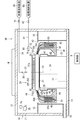
- FIG. 2 is a plan view of the processing unit 1.
- FIG. 3 is a vertical sectional view of the processing unit 1.
- the processing unit 1 includes a spin chuck 20, which is an example of a substrate holding portion, a first nozzle 30, a second nozzle 60, a third nozzle 65, a fixed nozzle 80, and a processing cup 40. Includes camera 70.
- the chamber 10 includes a side wall 11 along the vertical direction, a ceiling wall 12 that closes the upper side of the space surrounded by the side wall 11, and a floor wall 13 that closes the lower side.
- the space surrounded by the side wall 11, the ceiling wall 12, and the floor wall 13 is the processing space.
- a part of the side wall 11 of the chamber 10 is provided with a carry-in / out entrance for the main transfer robot 103 to carry in / out the substrate W and a shutter for opening / closing the carry-in / out port (both are not shown).
- a fan filter unit (FFU) 14 for further purifying the air in the clean room in which the substrate processing apparatus 100 is installed and supplying it to the processing space in the chamber 10 is attached to the ceiling wall 12 of the chamber 10. .
- the fan filter unit 14 includes a fan and a filter (for example, a HEPA (High Efficiency Particulate Air) filter) for taking in the air in the clean room and sending it out into the chamber 10, and the clean air is brought down to the processing space in the chamber 10.
- a punching plate having a large number of blowout holes may be provided directly under the ceiling wall 12.
- the spin chuck 20 holds the substrate W in a horizontal posture (a posture in which the normal line is along the vertical direction).
- the spin chuck 20 includes a disk-shaped spin base 21 fixed in a horizontal posture to the upper end of a rotating shaft 24 extending in the vertical direction.
- a spin motor 22 for rotating the rotating shaft 24 is provided below the spin base 21, a spin motor 22 for rotating the rotating shaft 24 is provided.
- the spin motor 22 rotates the spin base 21 in a horizontal plane via the rotation shaft 24.
- a cylindrical cover member 23 is provided so as to surround the spin motor 22 and the rotation shaft 24.
- the outer diameter of the disk-shaped spin base 21 is slightly larger than the diameter of the circular substrate W held by the spin chuck 20. Therefore, the spin base 21 has an upper surface 21a facing the entire lower surface of the substrate W to be held.
- a plurality of (four in this embodiment) chuck pins 26 are erected on the peripheral edge of the upper surface 21a of the spin base 21.
- the plurality of chuck pins 26 are evenly spaced along the circumference corresponding to the peripheral edge of the circular substrate W (at 90 ° intervals for four chuck pins 26 as in the present embodiment). Have been placed.
- Each chuck pin 26 is provided so as to be driveable between a holding position in contact with the peripheral edge of the substrate W and an open position away from the peripheral edge of the substrate W.
- the plurality of chuck pins 26 are driven in conjunction with each other by a link mechanism (not shown) housed in the spin base 21.
- the spin chuck 20 can hold the substrate W above the spin base 21 in a horizontal posture close to the upper surface 21a (FIG. 3). (See), the holding of the substrate W can be released by stopping the plurality of chuck pins 26 at their respective open positions.
- the lower end of the cover member 23 covering the spin motor 22 is fixed to the floor wall 13 of the chamber 10, and the upper end reaches directly below the spin base 21.
- a flange-shaped member 25 is provided which projects outward from the cover member 23 substantially horizontally and further bends downward and extends.
- the first nozzle 30 is configured by attaching a discharge head 31 to the tip of the nozzle arm 32.
- the base end side of the nozzle arm 32 is fixedly connected to the nozzle base 33.
- the nozzle base 33 is made rotatable around an axis along the vertical direction by a motor (not shown). As the nozzle base 33 rotates, the first nozzle 30 moves in an arc shape in the space above the spin chuck 20 as shown by the arrow AR34 in FIG.
- FIG. 4 is a plan view schematically showing an example of the movement path of the first nozzle 30.
- the discharge head 31 of the first nozzle 30 moves along the circumferential direction around the nozzle base 33 by the rotation of the nozzle base 33.
- the first nozzle 30 can be stopped at an appropriate position. In the example of FIG. 4, the first nozzle 30 can be stopped at each of the central position P31, the peripheral position P32, and the standby position P33.
- the central position P31 is a position where the discharge head 31 faces the central portion of the substrate W held by the spin chuck 20 in the vertical direction.
- the peripheral edge position P32 is a position where the discharge head 31 faces the peripheral edge portion of the substrate W held by the spin chuck 20 in the vertical direction.
- the first nozzle 30 may discharge the processing liquid onto the upper surface of the rotating substrate W in a state where the first nozzle 30 is located at the peripheral edge position P32.
- the treatment liquid can be discharged only to the peripheral edge portion of the upper surface of the substrate W, and only the peripheral edge portion of the substrate W can be treated (so-called bevel processing).
- the first nozzle 30 can also discharge the processing liquid onto the upper surface of the rotating substrate W while swinging between the central position P31 and the peripheral position P32. Also in this case, the entire surface of the upper surface of the substrate W can be processed.
- the first nozzle 30 does not have to discharge the processing liquid at the peripheral position P32.
- the peripheral edge position P32 may be a relay position that temporarily stands by when the first nozzle 30 moves from the central position P31 to the standby position P33.
- the standby position P33 is a position where the discharge head 31 does not face the substrate W held by the spin chuck 20 in the vertical direction.
- the standby position P33 may be provided with a standby pod that accommodates the discharge head 31 of the first nozzle 30.
- the first nozzle 30 is connected to the processing liquid supply source 36 via the supply pipe 34.
- a valve 35 is provided in the supply pipe 34. The valve 35 opens and closes the flow path of the supply pipe 34. When the valve 35 opens, the processing liquid supply source 36 supplies the processing liquid to the first nozzle 30 through the supply pipe 34.
- the first nozzle 30 may be configured to be supplied with a plurality of types of treatment liquids (including at least pure water).
- the processing unit 1 of the present embodiment is further provided with a second nozzle 60 and a third nozzle 65 in addition to the first nozzle 30.
- the second nozzle 60 and the third nozzle 65 of the present embodiment have the same configuration as the first nozzle 30 described above. That is, the second nozzle 60 is configured by attaching the discharge head 61 to the tip of the nozzle arm 62.
- the second nozzle 60 moves in an arc shape in the space above the spin chuck 20 by the nozzle base 63 connected to the base end side of the nozzle arm 62, as shown by the arrow AR64.
- the relative positional relationship between the central position P61, the peripheral edge position P62, and the standby position P63 located on the movement path of the second nozzle 60 is the relative positional relationship between the central position P31, the peripheral edge position P32, and the standby position P33, respectively. The same is true.
- the third nozzle 65 is configured by attaching a discharge head 66 to the tip of the nozzle arm 67.
- the third nozzle 65 moves in an arc shape in the space above the spin chuck 20 by the nozzle base 68 connected to the base end side of the nozzle arm 67, as shown by the arrow AR69. It moves in an arc shape between the processing position and the standby position outside the processing cup 40.
- the relative positional relationship between the central position P66, the peripheral edge position P67, and the standby position P68 located on the movement path of the third nozzle 65 is the relative positional relationship between the central position P31, the peripheral edge position P32, and the standby position P33, respectively. The same is true.
- the third nozzle 65 may be able to move up and down.
- the third nozzle 65 moves up and down by a nozzle raising and lowering mechanism (not shown) built in the nozzle base 68.
- the third nozzle 65 can also be stopped at the central upper position P69 located vertically above the central position P66.
- at least one of the first nozzle 30 and the second nozzle 60 may be provided so as to be able to move up and down.
- Each of the second nozzle 60 and the third nozzle 65 is also connected to the processing liquid supply source (not shown) via the supply pipe (not shown) like the first nozzle 30.
- a valve is provided in each supply pipe, and the supply / stop of the processing liquid can be switched by opening and closing the valve.
- Each of the second nozzle 60 and the third nozzle 65 may be configured to be supplied with a plurality of types of treatment liquids containing at least pure water. Further, at least one of the first nozzle 30, the second nozzle 60 and the third nozzle 65 mixes a cleaning liquid such as pure water with a pressurized gas to generate droplets, and the droplets and gas are generated. It may be a two-fluid nozzle that injects a mixed fluid with the substrate W onto the substrate W. Further, the number of nozzles provided in the processing unit 1 is not limited to three, and may be one or more.
- the processing unit 1 is also provided with a fixed nozzle 80.
- the fixed nozzle 80 is located above the spin chuck 20 and radially outside the outer peripheral edge of the spin chuck 20.
- the fixed nozzle 80 is provided at a position facing the processing cup 40 described later in the vertical direction.
- the discharge port of the fixed nozzle 80 faces the substrate W side, and its opening axis is, for example, along the horizontal direction.
- the fixed nozzle 80 also discharges the processing liquid onto the upper surface of the substrate W held by the spin chuck 20.
- the treatment liquid discharged from the fixed nozzle 80 is, for example, landed on the central portion of the upper surface of the substrate W.
- the fixed nozzle 80 is connected to the processing liquid supply source 83 via the supply pipe 81.
- a valve 82 is provided in the supply pipe 81.
- the valve 82 opens and closes the flow path of the supply pipe 81.
- the processing liquid supply source 83 supplies the processing liquid (for example, pure water) to the fixed nozzle 80 through the supply pipe 81, and the processing liquid is discharged from the discharge port of the fixed nozzle 80.
- the processing cup 40 surrounding the spin chuck 20 includes an inner cup 41, an inner cup 42, and an outer cup 43 that can be raised and lowered independently of each other.
- the inner cup 41 has a shape that surrounds the spin chuck 20 and is substantially rotationally symmetric with respect to the rotation axis CX that passes through the center of the substrate W held by the spin chuck 20.
- the inner cup 41 includes a bottom portion 44 having an annular shape in a plan view, a cylindrical inner wall portion 45 rising upward from the inner peripheral edge of the bottom portion 44, a cylindrical outer wall portion 46 rising upward from the outer peripheral edge of the bottom portion 44, and an inner wall.
- the first guide portion 47 that rises from between the portion 45 and the outer wall portion 46 and extends diagonally upward toward the center side (direction approaching the rotation axis CX of the substrate W held by the spin chuck 20) while drawing a smooth arc at the upper end portion.
- the cylindrical inner wall portion 48 rising upward from between the first guide portion 47 and the outer wall portion 46 are integrally included.
- the inner wall portion 45 is formed to have a length that allows the inner cup 41 to be accommodated with an appropriate gap between the cover member 23 and the flange-shaped member 25 in a state where the inner cup 41 is most raised.
- the middle wall portion 48 is housed in a state where the inner cup 41 and the middle cup 42 are closest to each other, while maintaining an appropriate gap between the second guide portion 52 described later of the middle cup 42 and the treatment liquid separation wall 53. It is formed to such a length.
- the first guide portion 47 has an upper end portion 47b extending diagonally upward on the center side (direction approaching the rotation axis CX of the substrate W) while drawing a smooth arc. Further, between the inner wall portion 45 and the first guide portion 47, there is a waste groove 49 for collecting and disposing of the used treatment liquid. Between the first guide portion 47 and the middle wall portion 48, there is an annular inner recovery groove 50 for collecting and collecting the used treatment liquid. Further, between the inner wall portion 48 and the outer wall portion 46, there is an annular outer recovery groove 51 for collecting and collecting a treatment liquid different from the inner recovery groove 50.
- the waste groove 49 is connected to an exhaust liquid mechanism (not shown) for discharging the treatment liquid collected in the waste groove 49 and forcibly exhausting the inside of the waste groove 49.
- an exhaust liquid mechanism (not shown) for discharging the treatment liquid collected in the waste groove 49 and forcibly exhausting the inside of the waste groove 49.
- four exhaust gas mechanisms are provided at equal intervals along the circumferential direction of the waste groove 49.
- the inner recovery groove 50 and the outer recovery groove 51 have a recovery mechanism for collecting the treatment liquid collected in the inner recovery groove 50 and the outer recovery groove 51 in a recovery tank provided outside the treatment unit 1. Both are connected (not shown).
- the bottoms of the inner recovery groove 50 and the outer recovery groove 51 are inclined by a slight angle with respect to the horizontal direction, and the recovery mechanism is connected to the lowest position thereof. As a result, the treatment liquid that has flowed into the inner recovery groove 50 and the outer recovery groove 51 is smoothly recovered.
- the middle cup 42 has a shape that surrounds the spin chuck 20 and is substantially rotationally symmetric with respect to the rotation axis CX that passes through the center of the substrate W held by the spin chuck 20.
- the middle cup 42 integrally includes a second guide portion 52 and a cylindrical processing liquid separation wall 53 connected to the second guide portion 52.
- the second guide portion 52 draws a smooth arc from the lower end portion 52a forming a coaxial cylindrical shape with the lower end portion of the first guide portion 47 and the upper end of the lower end portion 52a on the outside of the first guide portion 47 of the inner cup 41. It has an upper end portion 52b extending diagonally upward on the center side (direction approaching the rotation axis CX of the substrate W), and a folded portion 52c formed by folding the tip end portion of the upper end portion 52b downward.
- the lower end portion 52a is housed in the inner recovery groove 50 with an appropriate gap between the first guide portion 47 and the middle wall portion 48 in a state where the inner cup 41 and the middle cup 42 are closest to each other.
- the upper end portion 52b is provided so as to overlap the upper end portion 47b of the first guide portion 47 of the inner cup 41 in the vertical direction, and the first guide portion 47 is in a state where the inner cup 41 and the middle cup 42 are closest to each other. Close to the upper end 47b of the. Further, in the folded portion 52c formed by folding the tip of the upper end portion 52b downward, the folded portion 52c is the tip of the upper end portion 47b of the first guide portion 47 in a state where the inner cup 41 and the middle cup 42 are closest to each other. The length is such that it overlaps horizontally.
- the upper end portion 52b of the second guide portion 52 is formed so that the wall thickness becomes thicker toward the lower side, and the treatment liquid separation wall 53 is provided so as to extend downward from the lower end outer peripheral edge portion of the upper end portion 52b. It has a cylindrical shape.
- the treatment liquid separation wall 53 is housed in the outer recovery groove 51 with an appropriate gap between the inner wall portion 48 and the outer cup 43 in a state where the inner cup 41 and the middle cup 42 are closest to each other.
- the outer cup 43 surrounds the spin chuck 20 on the outside of the second guide portion 52 of the middle cup 42, and is substantially rotationally symmetric with respect to the rotation axis CX passing through the center of the substrate W held by the spin chuck 20. It has a shape.
- the outer cup 43 has a function as a third guide portion.
- the outer cup 43 has a lower end portion 43a coaxially cylindrical with the lower end portion 52a of the second guide portion 52, and a center side (direction approaching the rotation axis CX of the substrate W) while drawing a smooth arc from the upper end of the lower end portion 43a. It has an upper end portion 43b extending diagonally upward and a folded portion 43c formed by folding the tip end portion of the upper end portion 43b downward.
- the lower end portion 43a has an outer recovery groove with an appropriate gap between the treatment liquid separation wall 53 of the middle cup 42 and the outer wall portion 46 of the inner cup 41 in a state where the inner cup 41 and the outer cup 43 are closest to each other. It is housed in 51. Further, the upper end portion 43b is provided so as to overlap the second guide portion 52 of the middle cup 42 in the vertical direction, and the upper end portion 52b of the second guide portion 52 is in a state where the middle cup 42 and the outer cup 43 are closest to each other. Close to each other with a very small distance.
- the folded-back portion 43c and the folded-back portion 52c of the second guide portion 52 are in a state where the middle cup 42 and the outer cup 43 are closest to each other. It is formed so as to overlap in the horizontal direction.
- the inner cup 41, the middle cup 42 and the outer cup 43 can be raised and lowered independently of each other. That is, each of the inner cup 41, the middle cup 42, and the outer cup 43 is individually provided with a cup elevating mechanism (not shown), whereby the inner cup 41, the inner cup 42, and the outer cup 43 are individually and independently raised and lowered.
- a cup elevating mechanism various known mechanisms such as a ball screw mechanism and an air cylinder can be adopted.
- the partition plate 15 is provided so as to partition the inner space of the chamber 10 up and down around the processing cup 40.
- the partition plate 15 may be a single plate-shaped member surrounding the processing cup 40, or may be a combination of a plurality of plate-shaped members. Further, the partition plate 15 may be formed with a through hole or a notch penetrating in the thickness direction.
- the nozzle base 33 of the first nozzle 30 and the nozzle base 63 of the second nozzle 60 may be formed. And a through hole for passing a support shaft for supporting the nozzle base 68 of the third nozzle 65 is formed.
- the outer peripheral end of the partition plate 15 is connected to the side wall 11 of the chamber 10. Further, the edge portion of the partition plate 15 surrounding the processing cup 40 is formed so as to have a circular shape having a diameter larger than the outer diameter of the outer cup 43. Therefore, the partition plate 15 does not hinder the raising and lowering of the outer cup 43.
- an exhaust duct 18 is provided in the vicinity of the floor wall 13 which is a part of the side wall 11 of the chamber 10.
- the exhaust duct 18 is communicated with an exhaust mechanism (not shown).
- the air that has passed between the processing cup 40 and the partition plate 15 is discharged from the exhaust duct 18 to the outside of the device.
- the camera 70 is installed in the chamber 10 above the partition plate 15.
- the camera 70 includes, for example, a CCD (Charge Coupled Device), which is one of solid-state image pickup elements, and an optical system such as a lens.
- the camera 70 is provided to monitor various monitoring targets in the chamber 10, which will be described later. Specific examples of monitoring targets will be described in detail later.
- the camera 70 is arranged at a position that includes various monitoring targets in the imaging field of view.
- the camera 70 captures the imaging field of view at each frame rate, acquires captured image data, and sequentially outputs the acquired captured image data to the control unit 9.
- the illumination unit 71 is provided in the chamber 10 at a position above the partition plate 15.
- the control unit 9 may control the illumination unit 71 so that the illumination unit 71 irradiates light when the camera 70 performs imaging.
- the hardware configuration of the control unit 9 provided in the board processing device 100 is the same as that of a general computer. That is, the control unit 9 stores various information, a processing unit such as a CPU that performs various arithmetic processes, a temporary storage medium such as a ROM (ReaOnlyMemory) that is a read-only memory for storing a basic program, and various information. It includes a RAM (Random Access Memory), which is a readable and writable memory, and a non-temporary storage medium, such as a magnetic disk for storing control software or data.
- a processing unit such as a CPU that performs various arithmetic processes
- a temporary storage medium such as a ROM (ReaOnlyMemory) that is a read-only memory for storing a basic program
- ROM Read OnlyMemory
- control unit 9 When the CPU of the control unit 9 executes a predetermined processing program, each operation mechanism of the board processing device 100 is controlled by the control unit 9, and the processing in the board processing device 100 proceeds.
- the control unit 9 may be realized by a dedicated hardware circuit that does not require software to realize the function.
- FIG. 5 is a functional block diagram schematically showing an example of the internal configuration of the control unit 9.
- the control unit 9 includes a monitoring processing unit 91, a condition setting unit 92, and a processing control unit 93.
- the processing control unit 93 controls each configuration in the chamber 10. Specifically, the processing control unit 93 controls various valves such as the spin motor 22, valves 35 and 82, the motors of the nozzle bases 33, 63 and 68, the nozzle elevating mechanism, the cup elevating mechanism and the fan filter unit 14. .. When the processing control unit 93 controls these configurations according to a predetermined procedure, the processing unit 1 can perform processing on the substrate W. An example of a specific flow of processing for the substrate W will be described in detail later.
- the monitoring processing unit 91 performs monitoring processing based on the captured image data acquired by the camera 70 taking an image of the inside of the chamber 10. As a result, the monitoring processing unit 91 can monitor various monitoring targets in the chamber 10. Specific examples of the monitoring process will be described in detail later.
- the condition setting unit 92 identifies the monitoring target to be monitored and changes the imaging conditions of the camera 70 according to the monitoring target. Then, the condition setting unit 92 notifies the camera 70 of the imaging condition. Imaging conditions include, for example, at least one of resolution, frame rate and field of view. The camera 70 acquires the captured image data under the imaging conditions notified from the condition setting unit 92, and outputs the captured image data to the control unit 9. A specific example of the imaging conditions according to the monitoring target will be described in detail later.
- FIG. 6 is a flowchart showing an example of the flow of substrate processing.
- the main transfer robot 103 carries the unprocessed substrate W into the processing unit 1 (step S1: carry-in step).
- the spin chuck 20 holds the substrate W in a horizontal posture (step S2: holding step).
- the plurality of chuck pins 26 move to their respective contact positions, so that the plurality of chuck pins 26 hold the substrate W.
- step S3 rotation step
- step S4 cup raising step
- step S5 treatment liquid step
- the cup elevating mechanism appropriately switches the cup to be raised according to the type of the processing liquid supplied to the substrate W, but this point is the essence of the present embodiment. Since it is different from the above, the description thereof will be omitted below.
- FIG. 7 is a table showing an example of a specific procedure of the treatment liquid step (step S5).
- the treatment liquid process is defined by the steps ST1 to ST12.
- the table shows the time required for each step, the flow rate (discharge flow rate) of the processing liquid discharged from the first nozzle 30, the second nozzle 60, the third nozzle 65, and the fixed nozzle 80, and the first nozzle 30, the second nozzle 30.
- the positions of the nozzle 60 and the third nozzle 65 are shown.
- FIG. 7 also shows examples of monitoring processes and imaging conditions that can be executed in each step, which will be described in detail later.
- step ST1 the discharge flow rate of the processing liquid from the first nozzle 30, the second nozzle 60, the third nozzle 65, and the fixed nozzle 80 is zero over the required time t1, and the first nozzle 30 , The second nozzle 60 and the third nozzle 65 are stopped at the standby positions P33, P63, and P68, respectively.
- the required time t1 may be, for example, zero. In this case, step ST1 only shows the initial state.
- the nozzle base 33 moves the first nozzle 30 from the standby position P33 to the central position P31 in the required time t2.
- the required time t2 is, for example, about several seconds.
- the first nozzle 30 discharges the processing liquid onto the upper surface of the substrate W at the flow rate F30 in the required time t3.
- the treatment liquid that has landed on the upper surface of the substrate W receives centrifugal force due to the rotation of the substrate W, spreads on the upper surface of the substrate W, and scatters from the peripheral edge of the substrate W.
- the processing liquid scattered from the peripheral edge of the substrate W is received by the processing cup 40 and collected.
- the required time t3 is, for example, about several tens of seconds, and the flow rate F30 is, for example, about several thousand cc / min.
- the fixed nozzle 80 discharges the treatment liquid (for example, a rinse liquid) at the flow rate F80, and the nozzle base 33 moves the first nozzle 30 from the central position P31 to the peripheral position P32. ..
- the treatment liquid from the fixed nozzle 80 lands on the central portion of the upper surface of the substrate W, receives centrifugal force, spreads on the upper surface of the substrate W, and scatters from the peripheral edge of the substrate W.
- the processing liquid scattered from the peripheral edge of the substrate W is received by the processing cup 40 and collected.
- the required time t4 is, for example, about several tens of seconds
- the flow rate F80 is, for example, about several thousand cc / min.
- the fixed nozzle 80 continuously discharges the treatment liquid (for example, a rinse liquid) at the flow rate F80, while the nozzle base 33 moves the first nozzle 30 from the peripheral position P32 to the standby position P33 in the required time t5. Move it.
- the required time t5 is, for example, about several seconds.
- the fixed nozzle 80 continuously discharges the treatment liquid (for example, a rinse liquid) at the flow rate F80, while the nozzle base 63 moves the second nozzle 60 from the standby position P63 to the peripheral position P62 in the required time t6. Move it.
- the required time t6 is, for example, about several seconds.
- the fixed nozzle 80 discharges the processing liquid from the process ST4 to the process ST6.
- the treatment liquid discharged by the fixed nozzle 80 is a rinse liquid
- the treatment liquid remaining on the upper surface of the substrate W at the end of step ST3 can be replaced with the rinse liquid.
- the nozzle base 63 moves the second nozzle 60 from the peripheral position P62 to the central position P61, and the second nozzle 60 discharges the treatment liquid onto the upper surface of the substrate W at the flow rate F60. ..
- the required time t7 is, for example, about several tens of seconds, and the flow rate F60 is, for example, about several thousand cc / min.
- the upper surface of the substrate W can be processed.
- the nozzle base 63 moves the second nozzle 60 from the central position P61 to the standby position P63 in the required time t8.
- the required time t8 is, for example, about several seconds.
- the nozzle base 68 moves the third nozzle 65 from the standby position P68 to the center upper position P69 in the required time t9.
- the required time t9 is, for example, about several seconds.
- the third nozzle 65 discharges the treatment liquid onto the upper surface of the substrate W at a flow rate F65 at the required time t10.
- the required time t10 is, for example, about several tens of seconds, and the flow rate F65 is, for example, several thousand cc / min.
- the treatment liquid discharged by the third nozzle 65 is a rinse liquid, the treatment liquid remaining on the upper surface of the substrate W at the end of the step ST7 can be replaced with the rinse liquid.
- the nozzle base 63 lowers the third nozzle 65 from the central upper position P69 to the central position P65 in the required time t11.
- the required time t11 is, for example, about several tens of seconds.
- the nozzle base 63 moves the third nozzle 65 from the central position P65 to the standby position P68 in the required time t12.
- the required time t12 is, for example, about several seconds.
- step S6 drying step
- the spin motor 22 increases the rotation speed of the substrate W to dry the substrate W (so-called spin dry).
- step S7 cup lowering step
- step S8 holding release step
- the holding is released by moving the plurality of chuck pins 26 to their respective open positions.
- step S9 carry-out step
- the processing for the substrate W is performed.
- the monitoring processing unit 91 monitors the inside of the chamber 10 using the camera 70, and determines whether or not the processing for the substrate W is proceeding appropriately. As can be understood from the following description, the monitoring target monitored by the monitoring processing unit 91 changes sequentially according to the progress of the processing. Hereinafter, an example of the monitoring target in the chamber 10 will be described.
- the first nozzle 30, the second nozzle 60, and the third nozzle 65 move appropriately.
- the first nozzle 30 moves from the standby position P33 to the central position P31 in the step ST2.
- the first nozzle 30 may shift from the central position P31 and stop due to a motor abnormality of the nozzle base 33 or the like. In this case, the process in step ST3 may be improperly terminated.
- the position of the nozzle may be adopted as a monitoring target in the process (period) in which the nozzle moves.
- the process of performing the position monitoring process for monitoring the position of the nozzle is schematically shown by hatching with diagonal lines.
- a specific example of the position monitoring process will be described.
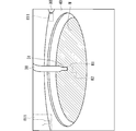
- FIG. 8 is a diagram schematically showing an example of captured image data acquired in the process of performing position monitoring processing.
- FIG. 8 shows an example of captured image data acquired in step ST2.
- the captured image data of FIG. 8 includes a discharge head 31 of the first nozzle 30 that stops at the central position P31. That is, FIG. 8 shows the captured image data acquired after the first nozzle 30 has moved from the standby position P33 to the central position P31 in the step ST2.
- the captured image data includes a processing cup 40 located at an upper position, a substrate W located inside the opening of the processing cup 40, and a fixed nozzle 80.
- the monitoring processing unit 91 analyzes the captured image data acquired in the process ST2 and detects the position of the first nozzle 30. For example, the monitoring processing unit 91 performs pattern matching between the reference image data RI1 including the first nozzle 30 (specifically, the ejection head 31) stored in the storage medium in advance and the captured image data in the captured image data. The position of the first nozzle 30 of the above is specified.
- the reference image data RI1 is schematically shown by a virtual line overlaid on the captured image data.
- the monitoring processing unit 91 determines whether or not the position of the detected first nozzle 30 is appropriate. For example, the monitoring processing unit 91 determines whether or not the difference between the position of the first nozzle 30 and the preset central position P31 is equal to or less than a predetermined nozzle position allowable value. The monitoring processing unit 91 determines that the first nozzle 30 is located at the central position P31 when the difference is equal to or less than the nozzle position allowable value. On the other hand, the monitoring processing unit 91 determines that the first nozzle 30 is not located at the central position P31 when the difference is larger than the nozzle position allowable value. That is, the monitoring processing unit 91 determines that the nozzle position abnormality has occurred.
- the monitoring processing unit 91 may notify a notification unit (for example, a display or a speaker) (not shown) of the abnormality. Further, the control unit 9 may stop the operation of the processing unit 1 to interrupt the processing for the substrate W. Since this point is the same in the following various monitoring processes, repeated explanations will be avoided below.
- a notification unit for example, a display or a speaker
- the monitoring processing unit 91 does not need to determine the suitability of the position while the first nozzle 30 is moving. Therefore, the monitoring processing unit 91 may determine that the first nozzle 30 has stopped when the position of the first nozzle 30 in a plurality of consecutive captured image data becomes constant. Then, the monitoring processing unit 91 may determine whether or not the difference between the position of the first nozzle 30 after stopping and the central position P31 is equal to or less than the nozzle position allowable value. That is, the monitoring processing unit 91 may determine whether or not the position of the first nozzle 30 is appropriate after the position of the first nozzle 30 is stabilized.
- the first nozzle 30 stops at the central position P31.
- the monitoring processing unit 91 does not need to perform the position monitoring processing in the step ST3.
- the monitoring processing unit 91 does not perform the position monitoring processing in the process ST3. According to this, it is possible to reduce the execution of unnecessary position monitoring processing, and it is possible to reduce the processing load of the monitoring processing unit 91.
- the monitoring processing unit 91 may also perform the position monitoring processing in the process ST4. Specifically, the monitoring processing unit 91 detects the position of the first nozzle 30 after stopping based on the captured image data, and determines whether or not the first nozzle 30 is appropriately stopped at the peripheral position P32. May be good. This suitability determination can also be performed in the same manner as described above.
- the monitoring processing unit 91 does not perform the position monitoring processing in the process ST5. That is, the monitoring processing unit 91 does not monitor the position of the first nozzle 30 with respect to the standby position P33. This is because even if the first nozzle 30 deviates from the standby position P33 and stops, the influence on the processing of the substrate W is small. Of course, the monitoring processing unit 91 may also perform position monitoring processing on the standby position P33.
- the monitoring processing unit 91 may also perform position monitoring processing on the second nozzle 60 and the third nozzle 65 at least in a process in which the positions change.
- the monitoring processing unit 91 since the second nozzle 60 moves in the process ST6 and the process ST7, the monitoring processing unit 91 performs a position monitoring process for monitoring the position of the second nozzle 60 in the process ST6 and the process ST7. Further, in the example of FIG. 7, since the third nozzle 65 moves in the process ST9 and the process ST11, the monitoring processing unit 91 performs a position monitoring process for monitoring the position of the third nozzle 65 in the process ST9 and the process ST11.
- the monitoring processing unit 91 performs position monitoring processing. No. Of course, the position monitoring process may be performed in these steps as well.
- the first nozzle 30, the second nozzle 60, the third nozzle 65, and the fixed nozzle 80 appropriately discharge the processing liquid.
- the first nozzle 30 discharges the processing liquid onto the upper surface of the substrate W in the required time t3 of the step ST3.
- the substrate W can be processed by appropriately discharging the processing liquid from the first nozzle 30.
- the state of the treatment liquid may be adopted as a monitoring target in the process in which each nozzle discharges the treatment liquid.
- the process of performing the treatment liquid monitoring process regarding the treatment liquid is schematically shown by hatching of sand.
- a specific example of the treatment liquid monitoring process will be described.
- ⁇ Discharge time> For example, if the discharge time at which the first nozzle 30 actually discharges the processing liquid deviates from the specified time in the process ST3, the processing in the process ST3 may be improperly terminated. Specifically, if the ejection time is too short, the processing for the substrate W is insufficient, and if the ejection time is too long, the processing for the substrate W becomes excessive.
- the discharge start timing and discharge stop timing of the treatment liquid, and eventually the discharge time may be adopted.
- the discharge time monitoring process for monitoring the discharge time of the processing liquid will be described.
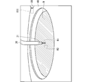
- FIG. 9 is a diagram schematically showing an example of captured image data acquired in the process of performing the discharge time monitoring process.
- FIG. 9 shows an example of captured image data acquired in step ST3.
- the captured image data of FIG. 9 includes the first nozzle 30 that discharges the processing liquid. That is, FIG. 9 shows the captured image data acquired after the first nozzle 30 starts discharging the processing liquid in the step ST3.
- the camera 70 sequentially acquires captured image data (for example, FIG. 8) including the first nozzle 30 that does not discharge the processing liquid.
- the camera 70 sequentially acquires captured image data (for example, FIG. 9) including the first nozzle 30 that ejects the processing liquid. Therefore, if it is possible to specify whether or not the first nozzle 30 is discharging the processing liquid for each of the captured image data acquired sequentially, the first nozzle 30 starts the processing liquid based on the specific result. The timing can be specified.
- the monitoring processing unit 91 determines whether or not the first nozzle 30 discharges the processing liquid for each captured image data.
- the ejection determination region R1 is set in the captured image data.
- the discharge determination region R1 includes a region extending in the discharge direction from the tip of the first nozzle 30 (that is, the tip of the discharge head 31).
- the discharge determination region R1 has, for example, a rectangular shape extending from the tip of the first nozzle 30 in the discharge direction (here, the lower side).
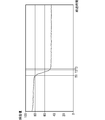
- the pixel values in the ejection determination region R1 are when the first nozzle 30 ejects the processing liquid and when the first nozzle 30 does not eject the processing liquid. Is different.
- the sum of the pixel values in the ejection determination region R1 when the first nozzle 30 is ejecting the processing liquid is the pixel value in the ejection determination region R1 when the first nozzle 30 is not ejecting the processing liquid. It will be larger than the sum of.
- the monitoring processing unit 91 determines whether or not the first nozzle 30 is discharging the processing liquid for each captured image data acquired in the step ST3 based on the pixel value of the discharge determination region R1. As a specific example, the monitoring processing unit 91 determines whether or not the sum of the pixel values in the ejection determination region R1 is equal to or greater than a predetermined ejection reference value, and when the sum is equal to or greater than the ejection reference value, the first is 1 It is determined that the nozzle 30 is discharging the processing liquid. Further, the monitoring processing unit 91 determines that the first nozzle 30 is not discharging the processing liquid when the total is less than the discharge reference value.
- the determination of the presence or absence of ejection of the processing liquid based on the pixel value in the ejection determination region R1 is not limited to this, and various methods can be adopted.
- the dispersion of the pixel values in the ejection determination region R1 when the first nozzle 30 is ejecting the processing liquid is larger than the dispersion when the first nozzle 30 is not ejecting the processing liquid. Therefore, the monitoring processing unit 91 may calculate the dispersion and determine whether or not the processing liquid is discharged based on the magnitude of the dispersion. It is also possible to use the standard deviation instead of the variance.
- the monitoring processing unit 91 is based on, for example, the acquisition timing of the captured image data in which the first nozzle 30 does not discharge the processing liquid and the acquisition timing of the captured image data in which the first nozzle 30 discharges the processing liquid. Identify the start timing.
- the monitoring processing unit 91 can also specify the end timing at which the first nozzle 30 ends the discharge of the processing liquid.
- the monitoring processing unit 91 calculates the difference between the discharge stop timing and the discharge start timing as the discharge time. Next, the monitoring processing unit 91 determines whether or not the discharge time is appropriate. For example, the monitoring processing unit 91 determines whether or not the difference between the discharge time and the specified time is equal to or less than a predetermined time allowable value. When the difference is equal to or less than the time allowable value, the monitoring processing unit 91 determines that the discharge time is appropriate. Further, the monitoring processing unit 91 determines that the discharge time is inappropriate when the difference is larger than the time allowable value. That is, the monitoring processing unit 91 determines that the discharge time abnormality has occurred.
- the discharge time monitoring process may be performed in each step of discharging the treatment liquid.
- the discharge time monitoring process for the second nozzle 60 and the third nozzle 65 is the same as that for the first nozzle 30.
- the fixed nozzle 80 discharges the processing liquid from the process ST4 to the process ST6.
- the monitoring processing unit 91 performs the processing liquid monitoring processing in the process ST4, but this processing liquid monitoring processing includes the liquid splash monitoring processing described later, and the discharge time monitoring processing for the fixed nozzle 80. Does not contain. Further, in the example of FIG. 7, the monitoring processing unit 91 does not perform the processing liquid monitoring processing in the process ST5 and the process ST6. However, the present invention is not limited to this, and the monitoring processing unit 91 may perform the ejection time monitoring processing for the fixed nozzle 80 in the steps ST4 to ST6.
- FIG. 10 is a diagram schematically showing an example of captured image data acquired in steps ST4 to ST6.
- the captured image data of FIG. 10 includes a fixed nozzle 80 for discharging the processing liquid. That is, FIG. 10 shows the captured image data acquired after the fixed nozzle 80 ejects the processing liquid.
- a discharge determination region R11 for determining the presence / absence of discharge of the processing liquid from the fixed nozzle 80 is set. Since the fixed nozzle 80 discharges the processing liquid along the horizontal direction, the discharge determination region R11 has, for example, a rectangular shape extending laterally from the tip of the fixed nozzle 80.
- the discharge time monitoring process using the discharge determination area R11 is the same as the discharge time monitoring process using the discharge determination area R1.
- the processing liquid may splash on the upper surface of the substrate W due to various factors such as, for example, the first nozzle 30 discharging the processing liquid onto the upper surface of the substrate W at a flow rate larger than the flow rate F30 (so-called liquid splash). ).
- the processing unit 1 cannot properly process the substrate W.
- the presence or absence of liquid splashing of the treatment liquid may be adopted as a monitoring target in the process in which each nozzle discharges the treatment liquid.
- a specific example of the liquid splash monitoring process for monitoring the presence or absence of liquid splash will be described.
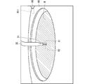
- FIG. 11 is a diagram schematically showing an example of captured image data acquired in step ST3.
- liquid splashes occur.
- the treatment liquid flowing down from the first nozzle 30 bounces off the upper surface of the substrate W, so that the treatment liquid bounces in a crown shape surrounding the liquid landing position.
- the liquid splash determination region R2 is set in the captured image data.
- the liquid splash determination region R2 may be set to a region including a part of the processing liquid splashing from the upper surface of the substrate W. Since the treatment liquid bounces around the liquid landing position, the liquid splash determination region R2 may be set next to, for example, the discharge determination region R1.
- the liquid splash determination region R2 is separated from the discharge determination region R1, and is located, for example, on the left side of the discharge determination region R1.
- the liquid splash determination region R2 has a rectangular shape.
- the pixel value in the liquid splash determination region R2 differs between when liquid splash does not occur (for example, FIG. 9) and when liquid splash occurs (for example, FIG. 11). For example, when light hits the treatment liquid splashed from the upper surface of the substrate W, the light is diffusely reflected. Therefore, the total of the pixel values of the liquid splash determination region R2 when the liquid splashes is that the liquid splashes do not occur. When the liquid splashes, it becomes larger than the sum of the pixel values in the determination region R2.
- the monitoring processing unit 91 determines whether or not liquid splashing has occurred for each captured image data acquired in step ST3, based on the pixel values in the liquid splash determination region R2. As a specific example, the monitoring processing unit 91 determines whether or not the sum of the pixel values in the liquid splash determination region R2 is equal to or greater than a predetermined liquid splash reference value, and the sum is the liquid splash reference value. When it is less than, it is judged that the liquid is not splashed. On the other hand, the monitoring processing unit 91 determines that liquid splashing has occurred when the total sum is equal to or higher than the liquid splashing reference value. That is, the monitoring processing unit 91 determines that a liquid splash abnormality has occurred.
- the determination of the presence or absence of liquid splash based on the pixel value in the liquid splash determination region R2 is not limited to this, and various methods can be adopted. For example, when light hits the treatment liquid splashed from the upper surface of the substrate W, the light is diffusely reflected. Therefore, when the liquid splashes, the dispersion of the pixel values in the liquid splash determination region R2 causes the liquid splashes. Greater than the variance when not. Therefore, the monitoring processing unit 91 may calculate the dispersion and determine the presence or absence of liquid splash based on the magnitude of the dispersion. It is also possible to use the standard deviation instead of the variance.
- the monitoring processing unit 91 performs a liquid splash monitoring process in the process of discharging the treatment liquid by each nozzle. Since the fixed nozzle 80 discharges the treatment liquid from its tip along the horizontal direction, the liquid splash tends to occur on the side opposite to the fixed nozzle 80 with respect to the liquid landing position. In the example of FIG. 11, since the liquid splash determination region R2 is located on the side opposite to the fixed nozzle 80 with respect to the liquid landing position, it is possible to detect the liquid splash accompanying the discharge of the processing liquid from the fixed nozzle 80. Can also be used.
- liquid splash monitoring process is performed in the process ST4 for the fixed nozzle 80
- the liquid splash monitoring process may also be performed in the process ST5 and the process ST6.
- the presence or absence of dripping may be adopted as a monitoring target in the process in which each nozzle discharges the treatment liquid.
- a specific example of the dripping monitoring process for monitoring the presence or absence of dripping will be described.
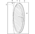
- FIG. 12 is a diagram schematically showing an example of captured image data acquired in step ST3.
- FIG. 12 shows captured image data acquired immediately after the first nozzle 30 stops discharging the processing liquid, and in the example of FIG. 12, dripping has occurred.
- the pixel values in the ejection determination region R1 are set when the first nozzle 30 is not ejecting the processing liquid (FIG. 8) and when the first nozzle 30 is ejected.
- FIG. 9 There is a difference between when the treatment liquid is being discharged (FIG. 9) and when dripping occurs (FIG. 12).
- the sum of the pixel values in the ejection determination region R1 when the dripping occurs is smaller than the sum of the pixel values in the ejection determination region R1 when the first nozzle 30 is ejecting the processing liquid. It is larger than the sum of the pixel values in the ejection determination region R1 when the first nozzle 30 is not ejecting the processing liquid.
- the monitoring processing unit 91 determines whether or not the dropout has occurred for each captured image data acquired in the step ST3 based on the pixel value of the ejection determination region R1.
- the monitoring processing unit 91 determines that the first nozzle 30 is discharging the processing liquid when the total sum of the pixel values in the discharge determination region R1 is equal to or greater than a predetermined first reference value.
- the sum of the pixel values in the ejection determination region R1 is less than the first reference value and equal to or more than the predetermined second reference value, it is determined that a dripping abnormality has occurred, and the sum of the pixel values in the ejection determination region R1 is summed.
- the second reference value it may be determined that the first nozzle 30 is not discharging the processing liquid.
- the determination of the presence or absence of dripping based on the pixel value in the ejection determination region R1 is not limited to this, and various methods can be adopted.
- the presence or absence of dripping may be determined based on the variance or standard deviation in the discharge determination region R1.
- each valve may open slightly due to an abnormality in each valve. In this case, the discharge of the processing liquid cannot be stopped properly, and the processing liquid continues to flow out from the nozzle (so-called outflow). In this case, since the processing liquid continues to be discharged to the upper surface of the substrate W, a processing defect may occur.
- the presence or absence of outflow may be adopted as a monitoring target in the process in which each nozzle discharges the treatment liquid.
- the outflow monitoring process for monitoring the presence / absence of outflow will be described.
- the outflow is an abnormality in which the processing liquid is discharged from the nozzle with the closing signal output to the valve. Since the valve is controlled by the processing control unit 93, the monitoring processing unit 91 can recognize whether or not a closing signal is output to the valve. Further, the monitoring processing unit 91 can determine whether or not the processing liquid is discharged from the nozzles based on the captured image data as described in the discharge time monitoring processing.
- the monitoring processing unit 91 determines that the first nozzle 30 is discharging the processing liquid even though the processing control unit 93 outputs a closing signal to the valve 35, the first nozzle 30 It is judged that an abnormal flow has occurred. The same applies to the second nozzle 60 and the third nozzle 65.
- the monitoring target changes according to each step defining the treatment liquid step (step S5).
- the monitoring target is, for example, the position of the first nozzle 30 during the execution period of the process ST2, and the state (shape) change (shape) of the processing liquid discharged from the first nozzle 30 during the execution period of the process ST3.
- the state change of the processing liquid is not the monitoring target and the nozzle position is the monitoring target.
- the nozzle position is not the monitoring target and the treatment liquid is discharged. The status is monitored. Further, both the position of the nozzle and the change of state of the processing liquid may be monitored, such as the execution period of the step ST7.
- the condition setting unit 92 sets the imaging conditions according to the monitoring target in each execution period.
- the imaging conditions in the execution period for example, step ST2 in which the nozzle position is monitored and the imaging in the execution period (for example, step ST3) in which the state change of the processing liquid is monitored.
- the conditions will be described, and then the imaging conditions during the execution period (for example, step ST7) in which both the nozzle position and the state change of the processing liquid are monitored will be described.
- ⁇ Nozzle position monitoring process> The higher the resolution of the captured image data, the finer and clearer the shape of each nozzle in the captured image data. Therefore, if the camera 70 acquires the captured image data for position monitoring processing at high resolution, the monitoring processing unit 91 can detect the position of the nozzle with higher accuracy based on the captured image data.
- condition setting unit 92 sets the resolution to a high resolution as an imaging condition when the camera 70 acquires the captured image data for the position monitoring process. Specifically, the condition setting unit 92 sets the resolution to a higher resolution as the imaging conditions in the process ST2, the process ST4, the process ST6, the process ST7, the process ST9, and the process ST11 (see also FIG. 7).
- the frame rate of the captured image data is low, problems are unlikely to occur in the position monitoring process. That is, since the nozzle stop position is monitored in the position monitoring process, there is no problem in the position monitoring process even if the frame rate is low. Further, even when monitoring the change of the nozzle position over time, the frame rate may be lowered if it is not necessary to detect the nozzle position at short time intervals.
- the condition setting unit 92 sets the resolution to a high resolution and the frame rate to a low frame rate as the imaging conditions in the execution period of the process ST2, the process ST6, the process ST9, and the process ST11.
- the condition setting unit 92 sets the resolution to a high resolution and the frame rate to a low frame rate as the imaging conditions of the captured image data not used in the processing liquid monitoring process but used in the position monitoring process.
- the condition setting unit 92 sets the resolution to high resolution and the frame rate to low frame rate as the imaging condition in the period in which the nozzle position is monitored without monitoring the state change of the processing liquid. do.
- the condition setting unit 92 notifies the camera 70 of the set imaging conditions.
- the camera 70 acquires captured image data according to the received imaging conditions. That is, the camera 70 acquires captured image data at a high resolution and a low frame rate in the process ST2, the process ST6, the process ST9, and the process ST11.
- the resolution can be changed, for example, by the binning function of the camera 70.
- the binning function is a function of changing the number of light receiving elements read out as one pixel among a plurality of light receiving elements of the camera 70. For example, consider the case where the light receiving surface of the camera 70 is composed of vertical Nx (for example, 2448) light receiving elements ⁇ horizontal Ny (for example, 2048) light receiving elements. By reading the data of each light receiving element as one pixel, the camera 70 can acquire the captured image data having Nx vertical ⁇ Ny horizontal pixels.
- the camera 70 reads out the data of a total of four light receiving elements, for example, 2 vertical ⁇ 2 horizontal, as one pixel, so that Nx / 2 (for example, 1224) vertical ⁇ Ny / 2 (for example, 1024) horizontal. Capturing image data having pixels can be acquired. Since the visual field range of the captured image data does not change, the resolution of the captured image data can be lowered.
- the frame rate can be changed, for example, by changing the cycle of opening the shutter (electronic shutter or mechanical shutter) of the camera 70.
- a high frame rate is, for example, 100 fps, and a low frame rate is, for example, 30 fps.
- the camera 70 acquires the captured image at a high resolution and a low frame rate, so that the monitoring processing unit 91 is based on the captured image data at the high resolution and the low frame rate. Performs position monitoring processing. Since the high-resolution captured image data is used, the monitoring processing unit 91 can detect the position of the nozzle with high accuracy. On the other hand, since the captured image data having a low frame rate is used, the processing load of the monitoring processing unit 91 can be reduced. Therefore, the power consumption can be reduced.
- ⁇ Treatment liquid monitoring process> The higher the frame rate of the captured image data, the shorter the time interval the camera 70 can acquire the captured image data. Therefore, it is easy to show the state change of the processing liquid discharged from each nozzle in the plurality of captured image data. For example, the higher the frame rate, the easier it is to capture the change from the state in which the processing liquid is not discharged to the state in which the processing liquid is discharged. Therefore, the higher the frame rate, the more accurately the monitoring processing unit 91 can monitor the discharge start timing of the processing liquid. The timing for stopping the discharge of the processing liquid is the same. As a result, the monitoring processing unit 91 can calculate the processing time with higher accuracy.
- the captured image data is acquired at shorter time intervals, so that the phenomenon can be reflected in the captured image data even if the phenomenon has a short occurrence period. For example, even if a liquid splash occurs momentarily due to a momentary increase in the discharge flow rate of the processing liquid caused by a flow rate fluctuation, if the frame rate is high, the camera 70 contains the liquid splash. Captured image data can be acquired.
- dripping occurs when the discharge of the treatment liquid is stopped, and the period of occurrence is not so long.
- the period during which outflow occurs may be short depending on the degree of valve abnormality. If the frame rate is high, the camera 70 can acquire the captured image data including the dripping or the outflow even if the dripping or the outflow occurs momentarily.
- condition setting unit 92 sets the frame rate to a high frame rate as the imaging conditions in the process ST3, the process ST4, the process ST7, and the process ST10. In short, the condition setting unit 92 sets the frame rate to a high frame rate as an image pickup condition when the camera 70 acquires the image pickup image data for the processing liquid monitoring process.
- the condition setting unit 92 sets the resolution to a low resolution and the frame rate to a high frame rate as the imaging conditions in the process ST3 and the process ST10.
- the condition setting unit 92 sets the resolution to a low resolution and the frame rate to a high frame as the imaging condition of the captured image data used in the processing liquid monitoring process without being used in the position monitoring process.
- the condition setting unit 92 sets the resolution to a low resolution and the frame rate to a high frame as an imaging condition during the period in which the state change of the processing liquid is monitored without monitoring the position of the nozzle. ..
- the condition setting unit 92 notifies the camera 70 of the set imaging conditions.
- the camera 70 acquires captured image data according to the received imaging conditions. Therefore, the monitoring processing unit 91 performs the processing liquid monitoring processing based on the captured image data acquired at low resolution and high frame rate in each of the process ST3 and the process ST10. According to this, since the captured image data having a high frame rate is used, the monitoring processing unit 91 monitors the discharge start timing, the discharge stop timing, the liquid splash, the dripping, and the outflow with higher accuracy. Can be done. Further, since the low-resolution captured image data is used, the processing load of the monitoring processing unit 91 can be reduced. Therefore, the power consumption can be reduced.
- the condition setting unit 92 sets the resolution to a high resolution and the frame rate to a higher frame rate as the imaging conditions in the process ST4 and the process ST7. In short, the condition setting unit 92 sets the resolution to a high resolution and the frame rate to a high frame rate as the imaging conditions of the captured image data used for both the position monitoring process and the processing liquid monitoring process. In other words, the condition setting unit 92 sets the resolution to a high resolution and the frame rate to a low frame rate as the imaging conditions during the period in which both the nozzle position and the state change of the processing liquid are monitored.
- the condition setting unit 92 notifies the camera 70 of the set imaging conditions.
- the camera 70 acquires captured image data according to the received imaging conditions. Therefore, the monitoring processing unit 91 performs both the position monitoring processing and the processing liquid monitoring processing based on the captured image data acquired at high resolution and high frame rate in each of the process ST4 and the process ST7. According to this, the position monitoring process and the processing liquid monitoring process can be performed with higher accuracy.
- recipe information indicating a substrate processing procedure is input to the control unit 9 from a device or a worker on the upstream side.
- the processing control unit 93 can perform processing on the substrate W by controlling the processing unit 1 based on the recipe information.
- the recipe information may include, for example, the "process", "time”, “discharge flow rate” and "position” information of FIG. 7.
- the condition setting unit 92 identifies the monitoring target in each process based on the recipe information, sets the imaging conditions as described above according to the monitoring target, and notifies the camera 70 of the imaging conditions.
- the condition setting unit 92 specifies the process in which the nozzle is moving based on the "position" information included in the recipe information, and adopts the nozzle position as a monitoring target in the process. Further, the condition setting unit 92 specifies the process in which the nozzle discharges the processing liquid based on the information of the "discharge flow rate" included in the recipe information, and adopts the state change of the processing liquid as a monitoring target in the process. .. Then, as described above, the condition setting unit 92 sets the imaging conditions in the execution period of each process according to the monitoring target in each process.
- the condition setting unit 92 does not necessarily have to specify the monitoring target in each process based on the recipe information. Information defining the processing procedure and the monitoring target may be input to the control unit 9 by the device or worker on the upstream side. According to this, the condition setting unit 92 can specify the monitoring target in each process by reading the information, and can set the imaging condition according to the monitoring target.
- FIG. 13 is a flowchart showing an example of the overall flow of the above-mentioned monitoring process.
- the condition setting unit 92 identifies the monitoring target in each process from a plurality of monitoring target candidates based on the processing procedure (for example, recipe information), and sets the imaging conditions in each process based on the monitoring target (step).
- S11 Condition setting process).
- the monitoring target candidate referred to here is a monitoring target before identification, and includes, for example, the position of the nozzle, the discharge start timing of the processing liquid, the discharge stop timing, the liquid splash, the dripping, the outflow, and the like. ..
- the camera 70 sequentially acquires captured image data based on the imaging conditions set by the condition setting unit 92 (step S12: imaging step). As a result, the camera 70 acquires the captured image data under the imaging conditions according to the monitoring target in each process.
- the monitoring processing unit 91 performs monitoring processing for the monitoring target in each process based on the captured image data captured under the imaging conditions according to the monitoring target (step S13: monitoring step).
- the imaging process and the monitoring process are executed in parallel with the processing for the substrate W. Thereby, the monitoring process can be performed during the process for the substrate W.
- the imaging conditions in all the steps may be set in advance before the processing on the substrate W, or the imaging conditions in each step may be sequentially set according to the progress of the processing on the substrate W.
- the condition setting unit 92 sets the imaging conditions according to the monitoring target, and notifies the camera 70 of the imaging conditions. Since the camera 70 acquires the captured image data under the notified imaging conditions, the captured image data can be acquired under the imaging conditions according to the monitoring target.
- the camera 70 acquires captured image data at a high resolution and a low frame rate during the execution period of the process in which the position of the nozzle is monitored without monitoring the state change of the processing liquid. Therefore, the monitoring processing unit 91 performs position monitoring processing based on captured image data having a high resolution and a low frame rate. According to this, it is possible to reduce the processing load by the low frame rate while monitoring the position of the nozzle with high accuracy based on the high-resolution captured image data.
- the camera 70 acquires the captured image data at a low resolution and a high frame rate. Therefore, the monitoring processing unit 91 performs the processing liquid monitoring processing based on the captured image data having a low resolution and a high frame rate. According to this, it is possible to reduce the processing load due to the low resolution while monitoring the state change of the processing liquid with high accuracy based on the captured image data having a high frame rate.
- the camera 70 acquires captured image data at a high resolution and a high frame rate during the execution period of the process in which both the nozzle position and the state change of the processing liquid are monitored. Therefore, the monitoring processing unit 91 can perform the position monitoring processing and the processing liquid monitoring processing with high accuracy.
- the monitoring target is not limited to the above-mentioned specific example, and various other monitoring targets in the chamber 10 can be adopted.
- the condition setting unit 92 may sequentially change the imaging conditions according to the change of the monitoring target, regardless of the type of the monitoring target. In the following, other specific examples of the monitoring target will be described.
- the spin chuck 20 holds the substrate W.
- the spin chuck 20 may not be able to hold the substrate W in an appropriate posture.
- the contact position between any one of the chuck pins 26 and the peripheral edge of the substrate W may shift in the vertical direction.
- the substrate W is held in an inclined posture. If the amount of deviation becomes large, the substrate W may ride on the chuck pin 26.
- the abnormality in which the spin chuck 20 cannot hold the substrate W in the horizontal posture is referred to as a holding abnormality. When such a holding abnormality occurs, it is not possible to properly process the substrate W.
- the shape of the substrate W may be abnormal.
- a step is generated at the cracked portion of the peripheral edge of the substrate W, and the peripheral edge of the substrate W does not have a circular shape.
- the peripheral edge of the substrate W does not have a circular shape. Even in such a case, there is a high possibility that the spin chuck 20 will not be able to hold the substrate W in the horizontal posture.
- an abnormality such as a crack in the substrate W is referred to as a shape abnormality. Even if such a shape abnormality occurs, it is not possible to properly process the substrate W.
- the presence or absence of holding abnormality and substrate shape abnormality may be adopted as monitoring targets.
- an example of the board monitoring process for monitoring the presence or absence of holding abnormality and substrate shape abnormality will be described.
- FIGS. 14 to 16 are diagrams schematically showing an example of captured image data acquired during the rotation process.
- 14 to 16 show captured image data acquired before the processing cup 40 was raised. That is, FIGS. 14 to 16 show captured image data in the steps from the start of the rotation step (step S3) to the cup raising step (step S4).
- FIG. 14 shows a state in which the spin chuck 20 holds the substrate W in a horizontal posture
- FIG. 15 shows a state in which the spin chuck 20 holds the substrate W in an inclined posture.
- FIG. Indicates a state in which the substrate W is cracked.
- the chuck pin 26 for holding the substrate W may be included in the captured image data, it is omitted in FIGS. 14 to 16 in order to avoid complication in the drawing.
- the peripheral edge (contour) shape of the substrate W is always constant.
- the peripheral edge of the substrate W in the captured image data has an elliptical shape.
- the peripheral shape of the substrate W is always constant.
- the position of the peripheral edge of the substrate W fluctuates slightly during the rotation of the substrate W.
- the rotation axis CX of the spin chuck 20 is not orthogonal to the substrate W. Therefore, when the spin chuck 20 rotates the substrate W, the peripheral shape of the substrate W is relatively significantly different in the plurality of captured image data. That is, the peripheral edge of the substrate W fluctuates greatly.
- the peripheral edges of the substrate W acquired at different timings are schematically shown by virtual lines.
- the peripheral edge of the substrate W when the peripheral edge of the substrate W is cracked, the shape of the peripheral edge of the substrate W moves away from the elliptical shape. In the example of FIG. 16, a step is formed on the peripheral edge of the substrate W due to cracking. Also in this case, when the spin chuck 20 rotates the substrate W, the positions of the peripheral edges of the substrate W are relatively significantly different in the plurality of captured image data. That is, the peripheral edge of the substrate W fluctuates greatly.
- the monitoring processing unit 91 obtains a difference in the peripheral shape of the substrate W among a plurality of captured image data sequentially acquired by the camera 70, and determines whether or not the difference is equal to or less than a predetermined substrate allowable value. ..
- the monitoring processing unit 91 determines that the spin chuck 20 holds the normal board W in the horizontal posture when the difference is equal to or less than the board allowable value, and holds the board W when the difference is larger than the board allowable value. Judge that an abnormality or an abnormality in the shape of the substrate has occurred.
- the monitoring processing unit 91 does not need to compare the entire peripheral shape of the substrate W between the captured image data. For example, the monitoring processing unit 91 captures the shape of a part of the peripheral edge of the substrate W on the front side or a part on the back side. The image data may be compared.
- the substrate determination region R3 is set in the captured image data.
- the substrate determination region R3 is a region including a part of the peripheral edge of the substrate W on the front side, and has a shape extending along the peripheral edge of the substrate W.
- the monitoring processing unit 91 cuts out the substrate determination area R3 from the captured image data, calculates the difference between the substrate determination areas R3 of the two captured image data, and acquires the difference image. Specifically, the monitoring processing unit 91 acquires a difference image by subtracting the pixel values of the pixels at the same position in the substrate determination area R3. By the subtraction, the pixel values in the same first region of the substrate determination region R3 are canceled out, and the pixel values in the second region different from each other are emphasized. That is, the absolute value of the pixel value of the pixel in the second region is larger than the absolute value of the pixel value of the pixel in the first region. Therefore, in the difference image, the region sandwiched between the peripheral edges of the substrate W in the two substrate determination regions R3 (hereinafter referred to as peripheral difference) is emphasized.
- peripheral difference the region sandwiched between the peripheral edges of the substrate W in the two substrate determination regions R3
- FIGS. 17 and 18 are diagrams schematically showing an example of an edge image.
- FIG. 17 shows an edge image when the spin chuck 20 holds the normal substrate W in the horizontal posture
- FIG. 18 shows an edge image when the spin chuck 20 holds the normal substrate W in the tilted posture.
- the edge 201 corresponds to the peripheral difference.
- the edge image includes a plurality of edges, the longest edge 201 extending in an arc shape corresponds to the peripheral difference.
- the circumferential length of the edge 201 when the normal substrate W is held in the horizontal posture is longer than the circumferential length of the edge 201 when the holding abnormality occurs. .. It is considered that this is because the vertical fluctuation of the peripheral edge of the substrate W at the time of holding abnormality is large, so that the position of the peripheral edge of the substrate W fluctuates in the vertical direction in a wider range in the circumferential direction. Even when the substrate W is cracked, the vertical variation of the peripheral edge of the substrate W becomes large, so that the length of the edge 201 in the circumferential direction becomes long.
- the monitoring processing unit 91 calculates the length of the edge 201 in the circumferential direction from the edge image, determines whether or not the length is equal to or less than the predetermined substrate reference value, and the length is equal to or less than the substrate reference value. At this time, it is determined that the spin chuck 20 holds the normal substrate W in the horizontal posture. On the other hand, the monitoring processing unit 91 determines that a holding abnormality or a shape abnormality of the substrate has occurred when the length is longer than the substrate reference value.
- the condition setting unit 92 sets the resolution to a high resolution as an imaging condition of the captured image data used for the substrate monitoring process.
- the condition setting unit 92 sets the resolution to a high resolution as an image pickup condition in the rotation period of the substrate W before the processing cup 40 rises.
- the monitoring processing unit 91 can detect the holding abnormality or the shape abnormality of the substrate with higher accuracy.
- the condition setting unit 92 may set the frame rate to a low frame rate as an imaging condition of the captured image data used for the substrate monitoring process. In other words, the condition setting unit 92 may set the frame rate to a low frame rate as an image pickup condition in the rotation period of the substrate W before the processing cup 40 rises. According to this, the processing load of the monitoring processing unit 91 can be reduced.
- the condition setting unit 92 may set the resolution to a low resolution.
- the presence or absence of holding abnormality or substrate shape abnormality does not necessarily have to be monitored during the rotation period of the substrate before the processing cup 40 is raised. If the process is such that the camera 70 can image the peripheral edge of the rotating substrate W, it is possible to monitor the holding abnormality or the shape abnormality of the substrate.
- step S2 when the spin chuck 20 holds the substrate W, the substrate W may shift with respect to the spin chuck 20 in a plan view. If the center of the substrate W deviates from the rotation axis CX of the spin chuck 20 by more than a predetermined eccentricity allowance value, the substrate W does not rotate properly in the rotation step (step S3).
- an abnormality in which the center of the substrate W deviates from the rotation axis CX by exceeding the eccentricity allowance value is referred to as an eccentricity abnormality. When such an eccentricity abnormality occurs, the substrate W may not be properly processed.
- an eccentricity abnormality of the substrate W may be adopted as a monitoring target.
- the eccentricity monitoring process for monitoring the presence or absence of eccentricity abnormality of the substrate W will be described.
- FIG. 19 is a diagram schematically showing an example of captured image data acquired during the rotation process.
- FIG. 19 shows captured image data acquired before the processing cup 40 was raised. That is, FIG. 19 shows the captured image data in the process from the start of the rotation process (step S3) to the cup raising process (step S4).
- FIG. 19 shows a state in which an eccentricity abnormality has occurred.
- the position of the peripheral edge of the substrate W changes according to the rotation position of the substrate W.
- the peripheral edge of the substrate W has an elliptical shape, and the point P1 at which the long axis thereof intersects the peripheral edge of the substrate W changes laterally according to the rotational position of the substrate W.
- the substrate W acquired at different timings is schematically shown by a virtual line.
- FIG. 20 is a graph showing an example of the relationship between the point P1 and the rotation angle ⁇ of the substrate W.
- the point P1 fluctuates in a sinusoidal shape with the rotation angle ⁇ as a variable.
- the lateral position of the point P1 in FIG. 20 is shown larger as it is located on the right side in FIG.
- the rotation angle ⁇ 1 when the point P1 becomes the largest indicates the eccentric direction of the substrate W
- the amplitude A1 of the point P1 indicates the amount of eccentricity between the substrate W and the rotation axis CX.
- the monitoring processing unit 91 detects the position of the point P1 in each of the plurality of captured image data. For example, the monitoring processing unit 91 performs edge extraction processing on each captured image data to acquire an edge image, identifies an elliptical edge having an elliptical shape from the edge image, and identifies the rightmost point of the elliptical edge as a point P1. You may. Alternatively, the monitoring processing unit 91 may calculate the ellipse approximation line closest to the ellipse edge by, for example, the least squares method, and calculate the intersection of the long axis of the ellipse approximation line and the ellipse approximation line as the point P1.
- the monitoring processing unit 91 performs curve interpolation such as spline interpolation processing for the rotation angle ⁇ of the substrate W at each acquisition timing when the camera 70 acquires the captured image data and the point P1 in each captured image data. Processing is performed to calculate the sine wave VL1 at the point P1. Next, the monitoring processing unit 91 calculates the amplitude A1 (eccentric amount) and the rotation angle ⁇ 1 (eccentric direction) based on the sine wave VL1.
- curve interpolation such as spline interpolation processing for the rotation angle ⁇ of the substrate W at each acquisition timing when the camera 70 acquires the captured image data and the point P1 in each captured image data. Processing is performed to calculate the sine wave VL1 at the point P1.
- the monitoring processing unit 91 calculates the amplitude A1 (eccentric amount) and the rotation angle ⁇ 1 (eccentric direction) based on the sine wave VL1.
- the monitoring processing unit 91 determines whether or not the eccentricity amount is equal to or less than the eccentricity allowable value, and when it is determined that the eccentricity amount is equal to or less than the eccentricity allowable value, it is determined that no eccentricity abnormality has occurred. On the other hand, the monitoring processing unit 91 determines that an eccentricity abnormality has occurred when the amount of eccentricity is larger than the allowable eccentricity value.
- the condition setting unit 92 sets the resolution to a high resolution as an imaging condition of the captured image data used for the eccentricity monitoring process. In other words, the condition setting unit 92 sets the resolution to a high resolution as an image pickup condition in the rotation period of the substrate W before the processing cup 40 rises. As a result, the monitoring processing unit 91 can detect the eccentricity abnormality with higher accuracy.
- the condition setting unit 92 may set the frame rate to a low frame rate as an imaging condition of the captured image data used for the eccentricity monitoring process. In other words, the condition setting unit 92 may set the frame rate to a low frame rate as an image pickup condition in the rotation period of the substrate W before the processing cup 40 rises. According to this, the processing load of the monitoring processing unit 91 can be reduced.
- step S1 the main transfer robot 103 carries the substrate W into the processing unit 1. For example, the main transfer robot 103 first moves the substrate W to the space above the spin chuck 20. Next, the main transfer robot 103 lowers the substrate W and delivers the substrate W to the spin chuck 20. If the delivery position (carry-in position) is deviated in a plan view, an eccentricity abnormality of the substrate W may occur. In the following, when the carry-in position deviates beyond a predetermined carry-in allowance value, it is referred to as a carry-in abnormality.
- the presence or absence of a carry-in abnormality of the board W may be adopted as a monitoring target.
- a specific example of the carry-in monitoring process for monitoring the presence or absence of an abnormality in the carry-in position of the substrate W will be described.
- the camera 70 sequentially acquires captured images in the carry-in process.
- the monitoring processing unit 91 detects the position of the center of the substrate W as the carry-in position based on the captured image data. For example, as described above, the monitoring processing unit 91 may acquire an edge image from the captured image data, specify an ellipse edge from the edge image, and calculate an ellipse approximation line from the ellipse edge. The monitoring processing unit 91 calculates the center of this elliptical approximation line as the position of the center of the substrate W.
- the monitoring processing unit 91 determines that the substrate W has been handed over to the spin chuck 20 when the position of the center of the substrate W becomes constant in a plurality of captured image data, and determines the position of the center of the substrate W. It may be specified as a carry-in position.
- the monitoring processing unit 91 determines whether or not the difference between the carry-in position and the predetermined reference carry-in position is less than or equal to the predetermined carry-in allowance value, and when the difference is less than or equal to the carry-in allowance value, the carry-in abnormality is detected. Judge that it has not occurred. On the other hand, when the difference is larger than the carry-in allowable value, the monitoring processing unit 91 determines that a carry-in abnormality has occurred.
- the condition setting unit 92 sets the resolution to a high resolution as an imaging condition of the captured image data used for the carry-in monitoring process.
- the condition setting unit 92 sets the resolution to a high resolution as an imaging condition during the execution period of the carry-in process.
- the monitoring processing unit 91 can detect the carry-in abnormality with higher accuracy.
- the condition setting unit 92 may set the frame rate to a low frame rate as the imaging condition of the captured image data used for the carry-in monitoring process. In other words, the condition setting unit 92 may set the frame rate to a low frame rate as an imaging condition during the execution period of the carry-in process. According to this, the processing load of the monitoring processing unit 91 can be reduced.
- the processing cup 40 may not be raised properly, for example, due to an abnormality in the cup raising / lowering mechanism. That is, the processing cup 40 may stop in a state of being displaced from a predetermined upper position. In this case, there is a possibility that the treatment liquid scattered from the peripheral edge of the substrate W cannot be properly recovered.
- a cup position abnormality an abnormality in which the processing cup 40 deviates from a predetermined cup reference position by exceeding a predetermined cup allowable value.
- the processing cup 40 may have a shape abnormality.
- the processing cup 40 may be deformed. If the treatment cup 40 has an abnormality in shape as described above, there is a possibility that the recovery of the treatment liquid may be inadequate.
- the abnormality in the shape of the processing cup 40 is referred to as a cup shape abnormality.
- the presence or absence of an abnormality in the cup position and an abnormality in the cup shape may be adopted as a monitoring target.
- a specific example of the cup monitoring process for monitoring the presence or absence of a cup position abnormality and a cup shape abnormality will be described.
- the camera 70 acquires captured image data in the cup ascending step (step S4).
- the monitoring processing unit 91 detects the position of the processing cup 40 based on the captured image data. For example, the monitoring processing unit 91 detects the position of the processing cup 40 by pattern matching between the reference image data obtained by imaging the normal processing cup 40 and the captured image data.
- the monitoring processing unit 91 determines whether or not the position of the processing cup 40 is appropriate after the processing cup 40 is stopped. More specifically, the monitoring processing unit 91 determines that the processing cup 40 is stopped when the position of the processing cup 40 is within a predetermined range in the plurality of captured image data, and determines whether the position of the processing cup 40 is appropriate or not. to decide. For example, the monitoring processing unit 91 determines whether the difference between the position of the processing cup 40 and the cup reference position is equal to or less than the predetermined cup position allowable value, and when the difference is equal to or less than the cup position allowable value, the cup position abnormality occurs. Is not occurring. On the other hand, the monitoring processing unit 91 determines that the cup position abnormality has occurred when the difference is larger than the cup position allowable value.
- the cup shape abnormality When the cup shape abnormality occurs, the difference between the region including the processing cup 40 in the captured image data and the reference image data including the normal processing cup 40 stopped at the normal position becomes large. .. Therefore, for example, the monitoring processing unit 91 calculates the difference between the reference image data and the captured image data, and acquires the difference image. Next, the monitoring processing unit 91 performs binarization processing on the difference image and acquires the binarized image. In the binarized image, the absolute value of the pixel value of the portion where the captured image data and the reference image data differ becomes large.
- the monitoring processing unit 91 obtains, for example, the area of a portion having a large pixel value, and determines whether or not the area is equal to or less than a predetermined cup shape allowable value. The monitoring processing unit 91 determines that no cup shape abnormality has occurred when the area is equal to or less than the cup shape allowable value, and when the area is larger than the cup shape allowable value, the processing cup 40 has a cup shape abnormality. Judge that it has occurred.
- the condition setting unit 92 sets the resolution to a high resolution as an imaging condition of the captured image data used for the processing cup monitoring process. In other words, the condition setting unit 92 sets the resolution to a high resolution as an imaging condition during the execution period of the cup raising step. According to this, the monitoring processing unit 91 can monitor the presence or absence of the cup position abnormality and the cup shape abnormality with high accuracy.
- the condition setting unit 92 may set the frame rate to a low frame rate as an imaging condition of the captured image data used for the processing cup monitoring process. In other words, the condition setting unit 92 may set the frame rate to a low frame rate as an imaging condition during the execution period of the cup rising step. According to this, the processing load of the monitoring processing unit 91 can be reduced.
- the cup monitoring process may be performed not only in the cup raising step (step S4) but also in the cup lowering step (step S7).
- the processing cup 40 not only the position but also the shape is monitored. Not only the position of the nozzle but also the shape may be monitored. That is, the monitoring processing unit 91 may monitor the presence or absence of an abnormality in the shape of the nozzle.
- FIG. 21 is a table showing imaging conditions according to the above-mentioned monitoring target.
- the resolution For data, set the resolution to high resolution.
- the condition setting unit 92 sets the resolution to a high resolution when the position or shape of the object in the chamber 10 is the monitoring target.
- the monitoring processing unit 91 can monitor the position or shape of the object with high accuracy.
- the condition setting unit 92 may set the frame rate to a low frame rate when the position or shape of the object in the chamber 10 is the monitoring target. In this case, the processing load of the monitoring processing unit 91 can be reduced.
- the frame rate of the captured image data used for the processing liquid monitoring process related to the start and discharge of the processing liquid from the nozzle, the liquid splashing, the dripping, the outflow, etc. of the processing liquid is set to a high frame rate.
- Set to rate That is, when the change of state of the treatment liquid in the chamber 10 with time is the monitoring target, the condition setting unit 92 sets the frame rate to a high frame rate.
- the monitoring processing unit 91 can monitor the change of state of the processing liquid over time with high accuracy.
- the condition setting unit 92 may set the resolution to a low resolution when the state change in the chamber 10 with time is the monitoring target. In this case, the processing load of the monitoring processing unit 91 can be reduced.
- the frame rate is set to a high frame rate while the resolution is set to high resolution. Set to.
- the monitoring processing unit 91 can monitor the position or shape of the object and the change of state of the processing liquid over time with high accuracy.
- the etching target on the upper surface of the substrate W is etched by the treatment liquid. Specifically, as time elapses from the start of ejection of the treatment liquid, the etching target is removed, and eventually the underlying layer located immediately below the etching target is exposed. If this etching processing time (discharging time of the processing liquid) deviates from the specified time, the etching becomes insufficient or excessive.
- the etching target on the upper surface of the substrate W is removed, the base layer is exposed, and the change appears in the captured image data. That is, since the light reflectances of the etching target and the base layer are different from each other, the pixel value of the pixel corresponding to the substrate W in the captured image data is between the state where the etching target is exposed and the state where the base layer is exposed. Is different. Therefore, it is possible to detect the timing (etching endpoint) at which the removal of the etching target of the substrate W is substantially completed by the time change of the pixel value.
- an etching endpoint may be adopted as a monitoring target.
- a specific example of the etching monitoring process for monitoring the etching endpoint will be described.
- FIG. 22 shows an example of captured image data acquired in step ST3.
- the captured image data in FIG. 22 includes the first nozzle 30 that discharges the etching solution. That is, FIG. 22 shows the captured image data acquired after the first nozzle 30 starts ejecting the etching solution.
- a plurality of etching determination regions R4 are set in the captured image data.
- the three etching determination regions R4 are arranged side by side from the central portion of the substrate W toward the peripheral edge side. That is, the three etching determination regions R4 are set at different positions in the radial direction with respect to the substrate W.
- FIG. 23 is a graph showing an example of time change of the luminance value in one etching determination region R4.
- the brightness value in the etching determination region R4 the total or average value of the pixel values in the etching determination region R4 is adopted.
- the luminance value is initially almost flat with respect to time.
- the luminance value decreases with the passage of time after the time point T1 when the ejection of the etching solution starts, and the luminance value becomes flat again with respect to the time after the time point T2.
- the etching target is gradually removed in the period between the time point T1 and the time point T2, so that the brightness value changes according to the removal of the etching target, whereas the etching target is completely removed at the time point T2. This is because.
- the monitoring processing unit 91 calculates, for example, the total or average value of the pixel values in the etching determination region R4 as the luminance value, and calculates the differential value which is the amount of change of the luminance value with respect to the unit time. Then, the monitoring processing unit 91 detects the time point when the differential value falls below the predetermined differential reference value as the time point T1, and detects the time point when the differential value exceeds the differential reference value as the time point T2.
- the time point T2 is the etching endpoint in the etching determination region R4.
- each etching determination region R4 may be different from each other. For example, when the first nozzle 30 discharges the etching solution to the central portion of the substrate W, the etching endpoint may be faster as the etching determination region R4 on the central side.
- each etching end point changes the moving speed of the first nozzle 30 and is on the swing path. It may change depending on the flow rate of the etching solution at each position.
- the etching endpoint of the central etching determination region R4 may be the fastest among the three etching determination regions R4.
- the processing control unit 93 may close the valve 35 and end the ejection of the etching liquid from the first nozzle 30 when the monitoring processing unit 91 can detect the etching endpoints of all the etching determination regions R4. According to this, it is possible to reduce the possibility of insufficient etching in all the etching determination regions R4.
- the condition setting unit 92 may set the resolution to a low resolution as an imaging condition of the captured image data used for the etching monitoring process. In other words, the condition setting unit 92 may set the resolution to a low resolution as an imaging condition during the execution period of the step ST3. As a result, the processing load of the monitoring processing unit 91 can be reduced.
- the condition setting unit 92 may set the frame rate to a low frame rate as an imaging condition of the captured image data used for the etching monitoring process. In other words, the condition setting unit 92 may set the frame rate to a low frame rate as an imaging condition during the execution period of the step ST3. As a result, the processing load of the monitoring processing unit 91 can be reduced.
- condition setting unit 92 sets the frame rate to a low frame rate as the imaging condition in the process ST3.
- FIG. 24 is a diagram schematically showing an example of the configuration of the processing unit 1A, which is another example of the processing unit 1.
- the processing unit 1A has the same configuration as the processing unit 1 except for the presence or absence of the heating unit 29.
- the heating unit 29 is a heating means for heating the substrate W.
- the heating unit 29 includes a disk-shaped hot plate 291 and a heater 292 that serves as a heat generating source.
- the hot plate 291 is arranged between the upper surface 21a of the spin base 21 and the lower surface of the substrate W held by the chuck pin 26.
- the heater 292 is embedded inside the hot plate 291.
- a heating wire such as a nichrome wire that generates heat by energization is used.
- the heater 292 is energized, the hot plate 291 is heated to a temperature higher than the environmental temperature.
- the third nozzle 65 discharges not only the processing liquid (for example, a rinsing liquid) but also the inert gas.
- the inert gas is a gas having low reactivity with the substrate W, and contains, for example, a rare gas such as argon gas or nitrogen.
- the discharge head of the third nozzle 65 is provided with a first internal flow path and a first discharge port for processing liquid, a second internal flow path and a second discharge port for gas, and the first internal flow path is provided. It is connected to the treatment liquid supply source through the first supply pipe, and the second internal flow path is connected to the gas supply source through the second supply pipe.
- the first supply pipe is provided with a first valve
- the second supply pipe is provided with a second valve.
- the flow of substrate processing by this processing unit 1A is the same as in FIG. 6, but the drying step (step S6) is different from the above-mentioned specific example.
- the camera 70 acquires captured image data in the drying process.
- 25 to 27 are diagrams schematically showing an example of captured image data acquired in the drying step. In the following, these captured image data will also be referred to.
- the third nozzle 65 moves from the standby position P68 to the center position P65.
- a rinse liquid having a higher volatility than, for example, pure water is supplied to the upper surface of the substrate W on which the third nozzle 65 is rotating.
- the rinse solution is, for example, IPA (isopropyl alcohol).
- the spin motor 22 stops the rotation of the substrate W, while the third nozzle 65 stops the discharge of the rinse liquid.
- the rinse liquid on the upper surface of the substrate W comes to rest. That is, a liquid film LF1 of the rinse liquid is formed on the upper surface of the substrate W (see FIG. 25).
- the heater 292 of the heating unit 29 is energized. As a result, the temperature of the heating unit 29 is raised, and the substrate W is heated by the heat of the heating unit 29.
- the lower layer portion in contact with the upper surface of the substrate W is also heated.
- the lower layer portion of the liquid film LF1 is vaporized.
- an IPA vapor layer is formed between the upper surface of the substrate W and the liquid film LF1. That is, the liquid film LF1 is in a state of floating from the upper surface of the substrate W.
- the third nozzle 65 discharges the inert gas.
- the inert gas is discharged toward the central portion of the liquid film LF1.
- the liquid film LF1 moves outward in the radial direction and flows out from the peripheral edge of the substrate W.
- a circular opening is formed in the central portion of the liquid film LF1 in a plan view (see FIG. 26). Since no treatment liquid such as a rinsing liquid is present in this opening, the opening is the dry region DR1.
- the dry region DR1 expands isotropically with the passage of time. That is, the dry region DR1 expands while maintaining a circular shape in a plan view.
- the dry region DR1 in the captured image data acquired at different timings is schematically shown by a virtual line.
- the third nozzle 65 stops the discharge of the inert gas and moves to the standby position P68. The energization of the heater 292 of the heating unit 29 is also stopped.
- the drying step it is difficult to stably form and expand the dry region DR1 as intended. That is, when a large number of substrates W are sequentially processed, the position, shape, or number of the drying region DR1 may not be in the intended state during the drying processing of some of the substrates W.
- the substrate W is heated to form a vapor layer of a rinse liquid between the upper surface of the substrate W and the liquid film LF1.
- fine bubbles may be generated in the liquid film LF1, and as a result, the opening DR2 may be generated in a part of the liquid film LF1 (see FIG. 27).
- the opening DR2 is generated in a part of the liquid film LF1 before the blowing of the inert gas, the vapor of the rinse liquid between the upper surface of the substrate W and the liquid film LF1 leaks from the opening DR2. Then, the vapor layer cannot be maintained and the drying process cannot be performed properly.
- the dry region DR1 is gradually expanded as described above by spraying the inert gas. At this time, the shape of the dry region DR1 may be deformed, or a plurality of dry regions DR1 may be generated. In this case as well, the drying step cannot be performed properly.
- drying abnormalities such abnormalities related to opening are collectively referred to as drying abnormalities.
- the drying abnormality is adopted as a monitoring target.
- the drying monitoring process for monitoring the presence or absence of drying abnormality will be described.
- FIG. 25 shows a state in which the liquid film LF1 of the rinse liquid is appropriately formed on the upper surface of the substrate W
- FIG. 27 shows a state in which an unintended opening DR2 is formed in the liquid film LF1 of the rinse liquid. Shows.
- the monitoring processing unit 91 calculates the difference between the reference image data (for example, FIG. 27) obtained by imaging a normal state and the captured image data, and acquires the difference image. If the opening DR2 is formed, the absolute value of the pixel value of the portion corresponding to the opening DR2 is high in the difference image. It can be said that the opening DR2 is formed when the area of the portion is large. Therefore, the monitoring processing unit 91 determines whether or not the area of the portion having a high absolute value of the pixel value is equal to or less than the predetermined drying allowable value, and when the area is equal to or less than the drying allowable value, a drying abnormality has occurred. Judge that there is no. On the other hand, the monitoring processing unit 91 determines that a drying abnormality has occurred when the area is larger than the drying allowable value.
- the reference image data for example, FIG. 27
- FIG. 28 is a diagram schematically showing an example of difference image data.
- the difference image data includes a closed curve C corresponding to the peripheral portion of the dry region DR1. If the dry region DR1 expands while maintaining a circular shape, the closed curve C forms an elliptical shape. When the shape of the dry region DR1 collapses, the closed curve C is distorted from the elliptical shape.
- the circularity R is an index showing how close the closed curve C is to a perfect circle.
- the circularity R is expressed by the following equation using the length L of the closed curve C and the area S of the closed curve C.
- the circularity R of the closed curve C when the closed curve C has an elliptical shape is higher than the circularity R when the closed curve C is distorted from the elliptical shape. Therefore, the monitoring processing unit 91 determines whether or not the circularity R of the closed curve C is equal to or greater than a predetermined drying reference value, and when the circularity R is equal to or greater than the drying reference value, no drying abnormality has occurred. to decide. On the other hand, the monitoring processing unit 91 determines that a drying abnormality has occurred when the circularity R is less than the drying reference value.
- the frame rate may be low.
- the condition setting unit 92 may set the resolution of the captured image data used for the drying monitoring process to a low resolution and the frame rate to a low frame rate. In other words, the condition setting unit 92 may set the resolution to a low resolution and the frame rate to a low frame rate as the imaging conditions during the execution period of the drying step. According to this, the monitoring processing unit 91 can monitor the drying abnormality with a low processing load.
- FIG. 29 is a diagram schematically showing an example of the configuration of the processing unit 1B, which is another example of the processing unit 1.
- the processing unit 1B has the same configuration as the processing unit 1 except for the presence or absence of the blocking plate 85.
- the blocking plate 85 is a member for suppressing the diffusion of gas near the upper surface of the substrate W.
- the cutoff plate 85 has a disk-shaped outer shape, and is arranged horizontally above the spin chuck 20.
- the cutoff plate 85 is connected to the cutoff plate elevating mechanism 86.
- the cutoff plate elevating mechanism 86 When the cutoff plate elevating mechanism 86 is operated, the cutoff plate 85 has an upper position separated upward from the upper surface of the substrate W held by the spin chuck 20 and a lower position closer to the upper surface of the substrate W than the upper position. Move up and down between.
- the cutoff plate elevating mechanism 86 for example, a mechanism that converts the rotary motion of the motor into a linear motion by a ball screw is used.
- an outlet 87 for blowing out an inert gas such as nitrogen gas is provided in the center of the lower surface of the blocking plate 85.
- the outlet 87 is connected to an air supply unit (not shown) that supplies a drying gas that is blown onto the substrate W in the drying step.
- the blocking plate 85 When the processing liquid is supplied to the substrate W from each of the first nozzle 30, the second nozzle 60, or the third nozzle 65, the blocking plate 85 is retracted to the upper position.
- the cutoff plate 85 When the substrate W is dried (step S6) after the treatment liquid step (step S4) with the treatment liquid is completed, the cutoff plate 85 is lowered to the lower position by the cutoff plate elevating mechanism 86. Then, a drying gas (for example, heated nitrogen gas) is sprayed from the outlet 87 toward the upper surface of the substrate W. At this time, the blocking plate 85 prevents the diffusion of gas. As a result, the drying gas is efficiently supplied to the upper surface of the substrate W.
- a drying gas for example, heated nitrogen gas
- the sulfuric acid supply source 36a and the hydrogen peroxide solution supply source 36b are connected to the first nozzle 30 via the supply pipe 34.
- the supply pipe 34 includes, for example, a merging supply pipe 341, a first supply pipe 342a, and a second supply pipe 342b.
- the downstream end of the merging supply pipe 341 is connected to the first nozzle 30, and the upstream end of the merging supply pipe 341 is connected to the downstream end of the first supply pipe 342a and the downstream end of the second supply pipe 342b.
- the upstream end of the first supply pipe 342a is connected to the sulfuric acid supply source 36a, and the upstream end of the second supply pipe 342b is connected to the hydrogen peroxide solution supply source 36b.
- the first supply pipe 342a is provided with a first valve 35a
- the second supply pipe 342b is provided with a second valve 35b.
- the flow of substrate processing by the processing unit 1B is the same as in FIG. 6, but in the processing liquid step (step S5), the first nozzle 30 treats a mixed liquid (SPM liquid) of sulfuric acid and hydrogen peroxide solution. Discharge as a liquid. Specifically, when the processing control unit 93 opens the first valve 35a and the second valve 35b, sulfuric acid and hydrogen peroxide are supplied to the first nozzle 30, and the first nozzle 30 transfers the mixed solution to the substrate W. Discharge toward.
- the temperature of the SPM liquid is, for example, 150 ° C to 200 ° C. Thereby, for example, the resist formed on the upper surface of the substrate W can be removed.
- the first valve 35a When the resist is sufficiently removed, the first valve 35a is closed and the supply of sulfuric acid is stopped. Since the hydrogen peroxide solution is supplied, the hydrogen peroxide solution pushes out the sulfuric acid in the merging supply pipe 341 and the first nozzle 30 (extrusion step). This makes it possible to reduce the possibility that sulfuric acid will unintentionally fall from the first nozzle 30 in the subsequent steps.
- the supply of sulfuric acid is stopped, so the proportion of hydrogen peroxide solution on the upper surface of the substrate W increases. Therefore, a large amount of hydrogen peroxide solution may react with sulfuric acid to generate an atmosphere consisting of a large number of fine particles called fume. If the amount of fume is normally generated, diffusion is suppressed by the downflow in the chamber 10. However, when the amount of fume generated becomes excessively large, for example, when fume adheres to the blocking plate 85, the adhered fume eventually solidifies into particles. Then, the particles may be scattered from the blocking plate 85 again and adhere to the surface of the substrate W as foreign matter. In the following, the anomaly in which the fume diffuses to a higher position is referred to as a fume anomaly.
- a fume abnormality may be adopted as a monitoring target.
- a specific example of the fume monitoring process for monitoring the presence or absence of a fume abnormality will be described.
- FIG. 30 is a diagram schematically showing an example of captured image data acquired in the extrusion process.
- the captured image data in FIG. 30 includes a fume.
- the fume extends to the vicinity of the lower surface of the blocking plate 85. That is, FIG. 30 shows a state in which a fume abnormality has occurred.
- a fume determination region R5 is set for the captured image data.
- the fume determination region R5 is a region above the substrate W and is a region where the fume does not reach in the normal extrusion process.
- the pixel value in the fume determination region R5 is different when the fume is present and when the fume is not present.
- the monitoring processing unit 91 determines whether or not a fume abnormality has occurred based on the pixel value of the fume determination region R5. For example, the monitoring processing unit 91 calculates the difference between the captured image data acquired before the generation of the fume and the captured image data acquired during the extrusion process, and acquires the difference image. Next, the monitoring processing unit 91 calculates the average value of the pixel values in the fume determination region R5 in the difference image. If the fume exists in the fume determination region R5, the average value becomes large.
- condition setting unit 92 may set the resolution to a low resolution and the frame rate to a low frame rate as the resolution condition of the captured image data used for the fume monitoring process.
- condition setting unit 92 may set the resolution to a low resolution and the frame rate to a low frame rate as the imaging conditions during the execution period of the extrusion process.
- the monitoring processing unit 91 can monitor the fume abnormality with a low processing load.
- the volatile components of the treatment liquid may adhere to each configuration in the chamber 10, and the configuration in the chamber 10 may crystallize.
- a crystal abnormality such an abnormality is referred to as a crystal abnormality.
- a crystal abnormality may be adopted as a monitoring target.
- a specific example of the crystal monitoring process for monitoring the presence or absence of crystal abnormality will be described.
- the crystal monitoring process is performed, for example, in a state where the substrate W has not been carried into the process unit 1 and each configuration in the process unit 1 is stopped at the initial position. That is, the crystal monitoring process is performed in a standby state in which the process for the substrate W is not performed. Further, this crystal monitoring process does not have to be performed for each process of the substrate W, for example, every time the number of processed sheets of the substrate W exceeds a predetermined number, or when a predetermined period has elapsed from the previous crystal monitoring process. Will be done.
- the monitoring processing unit 91 determines whether or not there is a crystal abnormality by comparing the reference image data acquired by imaging the normal chamber 10 in the standby state with the captured image data acquired by the camera 70. good.
- a crystal determination region to be crystallized is set in advance, and when the sum of the pixel values in the difference image between the reference image and the captured image data in the crystal determination region is large, it is determined that a crystal abnormality has occurred. You may.
- the condition setting unit 92 may set the resolution to a low resolution and the frame rate to a low frame rate as the imaging conditions of the captured image data used for the crystal monitoring process. In other words, the condition setting unit 92 may set the resolution to a low resolution and the frame rate to a low frame rate as the image pickup condition during the standby period when the processing unit 1 is stopped. According to this, the monitoring processing unit 91 can monitor the presence or absence of crystal abnormality with a low processing load.
- the condition setting unit 92 sets the frame rate to a low frame rate during the execution period of the process for monitoring the first abnormality (for example, drying abnormality, fume abnormality, crystal abnormality, etc.) that occurs in the first occurrence period. Set.
- the condition setting unit 92 is in the execution period of the process for monitoring the second abnormality (for example, liquid splash, dripping, outflow, etc.) that may occur in the second occurrence period shorter than the first occurrence period. , Set the frame rate to a high frame rate.
- the frame rate is set to a low first frame rate, so that the processing load of the monitoring processing unit 91 can be reduced. Further, in the second abnormality having a short occurrence period, the frame rate is set to a high second frame rate, so that the monitoring processing unit 91 can appropriately monitor the presence or absence of the second abnormality.
- the processing unit 1 may be provided with a chamber nozzle (not shown) for cleaning the inside of the chamber 10.
- This chamber nozzle discharges a cleaning liquid (for example, pure water) in the chamber 10 to clean various configurations in the chamber 10 (chamber cleaning step).
- This chamber cleaning step is executed in a state where the substrate W is not carried into the processing unit 1. That is, the chamber cleaning step is performed in a standby state in which the substrate W is not processed.
- the processing control unit 93 may discharge the cleaning liquid) from the chamber nozzle each time the substrate W is carried in to perform the chamber cleaning step, or each time the number of processed substrates W exceeds a predetermined number, the chamber may be cleaned.
- the cleaning step may be performed, or the chamber cleaning step may be performed when a predetermined period has elapsed from the previous chamber cleaning step.
- an abnormal discharge of the cleaning liquid discharged from the tip of the nozzle for the chamber may be adopted.
- a specific example of the chamber cleaning monitoring process will be described.
- the camera 70 sequentially acquires captured image data in the chamber cleaning process.
- the captured image data includes the tip of this chamber nozzle. Further, in the captured image data, a discharge determination region including a region extending from the tip of the chamber nozzle in the discharge direction is set.
- the monitoring processing unit 91 determines whether or not a ejection abnormality has occurred based on the pixel value in the ejection determination region of the captured image data. For example, the ejection abnormality may be determined by comparing the determination ejection area of the reference image data when the processing liquid is normally ejected with the determination ejection area of the captured image data.
- the condition setting unit 92 may set the resolution to a low resolution and the frame rate to a low frame rate as the imaging conditions of the captured image data used for the chamber cleaning monitoring process. In other words, the condition setting unit 92 may set the resolution to a low resolution and the frame rate to a low frame rate as the imaging conditions during the execution period of the chamber cleaning step. According to this, the monitoring processing unit 91 can monitor the presence or absence of a discharge abnormality with a low processing load.
- imaging conditions ⁇ Other examples of imaging conditions>
- the size of the visual field range reflected in the captured image data may be adopted.
- the camera 70 can image the inside of the chamber 10 in the field of view V1 (see FIG. 2), and can image the inside of the chamber 10 in the field of view V2.
- the field of view V1 is wider than the field of view V2.
- the viewing angle of the viewing range V1 in the plan view is, for example, 120 degrees
- the viewing angle of the viewing range V2 is, for example, 60 degrees.
- the captured image data acquired in the visual field range V2 includes the entire opening of the processing cup 40, but includes only the vicinity of the opening.
- the captured image data acquired in the visual field range V1 includes the entire opening of the processing cup 40 and a region farther from the opening.
- FIG. 31 is a diagram schematically showing an example of captured image data having different visual field ranges.
- the captured image data acquired in the wide visual field range V1 among the captured image data acquired in the wide visual field range V1, the captured image data obtained by cutting out a predetermined region as the visual field range V2 corresponds to the captured image data acquired in the visual field range V2. Therefore, the amount of data of the captured image data in the visual field range V2 is smaller than the amount of data of the captured image data in the visual field range V1.
- the camera 70 can adjust the field of view, for example, by cutting out a part of the image data read from all the light receiving elements. Alternatively, the camera 70 may read out the data of only the light receiving element in the region designated as the field of view range. This also allows the camera 70 to change the field of view.
- the condition setting unit 92 may set the visual field range according to the monitoring target.
- FIG. 32 is a table showing an example of the monitoring target and the imaging condition.
- the resolution may be set to either high resolution or low resolution for the shape abnormality of the substrate W.
- the algorithms for monitoring the shape abnormality and the holding abnormality of the substrate W are the same, it is preferable to set the resolution to a high resolution when also monitoring the holding abnormality.
- condition setting unit 92 may adopt the imaging condition having the higher data amount as the imaging condition during the period in which the monitoring processing for a plurality of monitoring targets is performed in parallel. For example, when both the monitoring process requiring a large field of view and the monitoring process not requiring a large field of view are performed in parallel, the condition setting unit 92 sets the field of view to a large field of view as an imaging condition in the process. Set. For example, in the extrusion step of extruding sulfuric acid with hydrogen peroxide solution and ejecting it from the first nozzle 30, it is conceivable to perform monitoring processing for both the fume abnormality and the ejection state of the processing liquid. In this case, the condition setting unit 92 sets the visual field range to a large range, the resolution to a low resolution, and the frame rate to a high frame rate as the imaging conditions in the extrusion process.
- the condition setting unit 92 sets the imaging conditions of the camera 70.
- the camera 70 may acquire captured image data under predetermined imaging conditions.
- predetermined imaging conditions for example, the field of view is set to a large field of view, the resolution is set to high resolution, and the frame rate is set to a high frame rate.
- the control unit 9 may change the image conditions of the captured image data by performing image processing on the captured image data received from the camera 70.
- the image conditions referred to here are the same as the imaging conditions. However, the image conditions are not directly used to control the camera 70.
- the image conditions are, for example, the visual field range, resolution and frame rate of the captured image data.
- FIG. 33 is a functional block diagram schematically showing an example of the internal configuration of the control unit 9.
- the control unit 9 includes a monitoring processing unit 91, a condition setting unit 92, a processing control unit 93, and a preprocessing unit 94.
- the preprocessing unit 94 changes the image conditions of the captured image data received from the camera 70. For example, the preprocessing unit 94 acquires captured image data having a small field of view range V2 by cutting out a part of the captured image data. Further, the preprocessing unit 94 averages the pixel values of adjacent vertical nx x horizontal ny pixels in the captured image data and makes them one pixel, so that the captured image data has a low resolution. To get. Further, the preprocessing unit 94 acquires captured image data having a low frame rate by, for example, skipping at least one captured image data sequentially acquired and deleting at least one captured image data.
- condition setting unit 92 identifies the monitoring target from the monitoring target candidates in the chamber 10 and sets the image conditions according to the monitoring target.
- the pre-processing unit 94 performs the above-mentioned processing on the captured image data so that the image conditions of the captured image data received from the camera 70 match the image conditions set by the condition setting unit 92.
- the monitoring processing unit 91 executes monitoring processing for the monitoring target based on the captured image data processed by the preprocessing unit 94.
- the monitoring processing unit 91 can monitor the monitoring target based on the captured image data having the image conditions according to the monitoring target. Therefore, even if the camera 70 cannot change the imaging conditions, the monitoring processing unit 91 can monitor the monitoring target based on the captured image data having the image conditions according to the monitoring target. According to this, as described above, the monitored object can be monitored with high accuracy. Further, the processing load of the monitoring processing unit 91 can be appropriately reduced.
- the substrate processing method and the substrate processing apparatus 100 have been described in detail, but the above description is an example in all aspects, and the substrate processing apparatus is not limited thereto. It is understood that a myriad of variants not illustrated can be envisioned without departing from the scope of this disclosure. The configurations described in the above embodiments and the modifications can be appropriately combined or omitted as long as they do not conflict with each other.
- the field of view range, resolution and frame rate are adopted as image conditions, but the image conditions are not necessarily limited to this.
- image conditions such as the exposure time and white balance of the camera 70 may be changed according to the monitoring target.
- condition setting unit 92 changes the image condition by a binary value.
- the condition setting unit 92 sets the resolution to either high resolution or low resolution according to the monitoring target.
- the condition setting unit 92 may change the image condition (for example, resolution) more finely according to the monitoring target.
- Processing unit 10 Chamber 20 Spin chuck 30 Nozzle (1st nozzle) 40 Processing cup 60 Nozzles (2nd nozzle) 65 nozzles (3rd nozzle) 80 nozzles (fixed nozzles) 9 Control unit 70 Camera 100 Board processing device W board
Landscapes
- Engineering & Computer Science (AREA)
- Microelectronics & Electronic Packaging (AREA)
- Condensed Matter Physics & Semiconductors (AREA)
- General Physics & Mathematics (AREA)
- Manufacturing & Machinery (AREA)
- Computer Hardware Design (AREA)
- Physics & Mathematics (AREA)
- Power Engineering (AREA)
- Cleaning Or Drying Semiconductors (AREA)
- Coating Apparatus (AREA)
- Weting (AREA)
- Exposure Of Semiconductors, Excluding Electron Or Ion Beam Exposure (AREA)
- Container, Conveyance, Adherence, Positioning, Of Wafer (AREA)
- Manufacturing Of Printed Circuit Boards (AREA)
Abstract
Selon l'invention, un procédé de traitement de substrat comprend : une étape de retenue consistant à porter un substrat à l'intérieur d'une chambre et à retenir le substrat ; une étape d'alimentation consistant à fournir un fluide au substrat à l'intérieur de la chambre ; une étape d'imagerie (S12) consistant à imager de manière séquentielle l'intérieur de la chambre par une caméra et acquérir des données d'image ; une étape de réglage de condition (S11) consistant à spécifier l'objet à surveiller à partir d'une pluralité d'options pour l'objet à surveiller à l'intérieur de la chambre et modifier des conditions d'image sur la base de l'objet à surveiller ; et une étape de surveillance (S13) consistant à réaliser un traitement de surveillance portant sur l'objet à surveiller en fonction des données d'image avec des conditions d'image appropriées à l'objet à surveiller.
Priority Applications (4)
| Application Number | Priority Date | Filing Date | Title |
|---|---|---|---|
| EP21812075.6A EP4159325A1 (fr) | 2020-05-27 | 2021-05-12 | Procédé de traitement de substrat et dispositif de traitement de substrat |
| KR1020227041083A KR20230003014A (ko) | 2020-05-27 | 2021-05-12 | 기판 처리 방법 및 기판 처리 장치 |
| CN202180038150.XA CN115668451A (zh) | 2020-05-27 | 2021-05-12 | 基板处理方法及基板处理装置 |
| US17/924,644 US20230241634A1 (en) | 2020-05-27 | 2021-05-12 | Substrate processing method and substrate processing apparatus |
Applications Claiming Priority (2)
| Application Number | Priority Date | Filing Date | Title |
|---|---|---|---|
| JP2020092559A JP7443163B2 (ja) | 2020-05-27 | 2020-05-27 | 基板処理方法および基板処理装置 |
| JP2020-092559 | 2020-05-27 |
Publications (1)
| Publication Number | Publication Date |
|---|---|
| WO2021241228A1 true WO2021241228A1 (fr) | 2021-12-02 |
Family
ID=78745272
Family Applications (1)
| Application Number | Title | Priority Date | Filing Date |
|---|---|---|---|
| PCT/JP2021/018027 WO2021241228A1 (fr) | 2020-05-27 | 2021-05-12 | Procédé de traitement de substrat et dispositif de traitement de substrat |
Country Status (7)
| Country | Link |
|---|---|
| US (1) | US20230241634A1 (fr) |
| EP (1) | EP4159325A1 (fr) |
| JP (1) | JP7443163B2 (fr) |
| KR (1) | KR20230003014A (fr) |
| CN (1) | CN115668451A (fr) |
| TW (1) | TWI817127B (fr) |
| WO (1) | WO2021241228A1 (fr) |
Cited By (2)
| Publication number | Priority date | Publication date | Assignee | Title |
|---|---|---|---|---|
| WO2023153229A1 (fr) * | 2022-02-08 | 2023-08-17 | 東京エレクトロン株式会社 | Procédé de traitement de liquide, procédé de réglage de sortie et dispositif de traitement de liquide |
| WO2023167097A1 (fr) * | 2022-03-01 | 2023-09-07 | 株式会社Screenホールディングス | Dispositif de traitement de substrat, système de traitement de substrat et procédé de traitement de substrat |
Families Citing this family (5)
| Publication number | Priority date | Publication date | Assignee | Title |
|---|---|---|---|---|
| JP2023137511A (ja) * | 2022-03-18 | 2023-09-29 | 株式会社Screenホールディングス | 基板処理装置および監視方法 |
| TW202347550A (zh) * | 2022-03-29 | 2023-12-01 | 日商東京威力科創股份有限公司 | 基板處理裝置、其檢查方法及基板處理系統 |
| WO2023243438A1 (fr) * | 2022-06-16 | 2023-12-21 | 東京エレクトロン株式会社 | Dispositif de traitement de substrat et procédé de traitement de substrat |
| TW202403948A (zh) * | 2022-06-17 | 2024-01-16 | 日商東京威力科創股份有限公司 | 基板處理裝置及基板處理方法 |
| JP2024058886A (ja) * | 2022-10-17 | 2024-04-30 | 株式会社Ihiインフラシステム | 塗装具 |
Citations (4)
| Publication number | Priority date | Publication date | Assignee | Title |
|---|---|---|---|---|
| JP2008135679A (ja) | 2006-10-25 | 2008-06-12 | Tokyo Electron Ltd | 液処理装置、液処理方法及び記憶媒体 |
| JP2013214279A (ja) * | 2012-03-07 | 2013-10-17 | Tokyo Electron Ltd | 半導体製造装置のプロセス監視装置及び半導体製造装置のプロセス監方法並びに半導体製造装置 |
| JP2015173148A (ja) | 2014-03-11 | 2015-10-01 | 株式会社Screenホールディングス | 基板処理装置および基板処理方法 |
| WO2021095612A1 (fr) * | 2019-11-15 | 2021-05-20 | 東京エレクトロン株式会社 | Dispositif de surveillance, dispositif de traitement de substrat, procédé de surveillance et support de stockage |
Family Cites Families (4)
| Publication number | Priority date | Publication date | Assignee | Title |
|---|---|---|---|---|
| US7202155B2 (en) * | 2003-08-15 | 2007-04-10 | Semiconductor Energy Laboratory Co., Ltd. | Method for manufacturing wiring and method for manufacturing semiconductor device |
| US7827930B2 (en) * | 2004-01-26 | 2010-11-09 | Applied Materials, Inc. | Apparatus for electroless deposition of metals onto semiconductor substrates |
| KR101276392B1 (ko) * | 2004-02-03 | 2013-06-19 | 가부시키가이샤 니콘 | 노광 장치 및 디바이스 제조 방법 |
| US20190217327A1 (en) * | 2018-01-15 | 2019-07-18 | Tokyo Electron Limited | System and Method for Fluid Dispense and Coverage Control |
-
2020
- 2020-05-27 JP JP2020092559A patent/JP7443163B2/ja active Active
-
2021
- 2021-05-12 CN CN202180038150.XA patent/CN115668451A/zh active Pending
- 2021-05-12 EP EP21812075.6A patent/EP4159325A1/fr active Pending
- 2021-05-12 WO PCT/JP2021/018027 patent/WO2021241228A1/fr unknown
- 2021-05-12 KR KR1020227041083A patent/KR20230003014A/ko unknown
- 2021-05-12 US US17/924,644 patent/US20230241634A1/en active Pending
- 2021-05-21 TW TW110118359A patent/TWI817127B/zh active
Patent Citations (4)
| Publication number | Priority date | Publication date | Assignee | Title |
|---|---|---|---|---|
| JP2008135679A (ja) | 2006-10-25 | 2008-06-12 | Tokyo Electron Ltd | 液処理装置、液処理方法及び記憶媒体 |
| JP2013214279A (ja) * | 2012-03-07 | 2013-10-17 | Tokyo Electron Ltd | 半導体製造装置のプロセス監視装置及び半導体製造装置のプロセス監方法並びに半導体製造装置 |
| JP2015173148A (ja) | 2014-03-11 | 2015-10-01 | 株式会社Screenホールディングス | 基板処理装置および基板処理方法 |
| WO2021095612A1 (fr) * | 2019-11-15 | 2021-05-20 | 東京エレクトロン株式会社 | Dispositif de surveillance, dispositif de traitement de substrat, procédé de surveillance et support de stockage |
Cited By (2)
| Publication number | Priority date | Publication date | Assignee | Title |
|---|---|---|---|---|
| WO2023153229A1 (fr) * | 2022-02-08 | 2023-08-17 | 東京エレクトロン株式会社 | Procédé de traitement de liquide, procédé de réglage de sortie et dispositif de traitement de liquide |
| WO2023167097A1 (fr) * | 2022-03-01 | 2023-09-07 | 株式会社Screenホールディングス | Dispositif de traitement de substrat, système de traitement de substrat et procédé de traitement de substrat |
Also Published As
| Publication number | Publication date |
|---|---|
| KR20230003014A (ko) | 2023-01-05 |
| TW202403870A (zh) | 2024-01-16 |
| US20230241634A1 (en) | 2023-08-03 |
| TWI817127B (zh) | 2023-10-01 |
| JP7443163B2 (ja) | 2024-03-05 |
| CN115668451A (zh) | 2023-01-31 |
| JP2021190511A (ja) | 2021-12-13 |
| EP4159325A1 (fr) | 2023-04-05 |
| TW202201524A (zh) | 2022-01-01 |
Similar Documents
| Publication | Publication Date | Title |
|---|---|---|
| WO2021241228A1 (fr) | Procédé de traitement de substrat et dispositif de traitement de substrat | |
| TWI613010B (zh) | 基板處理裝置及基板處理方法 | |
| JP6423672B2 (ja) | 基板処理装置および基板処理方法 | |
| US10651064B2 (en) | Substrate treatment device and substrate treatment method | |
| JP7211751B2 (ja) | 基板処理装置および基板処理方法 | |
| JP7179568B2 (ja) | 基板処理方法および基板処理装置 | |
| JP6251086B2 (ja) | 基板処理装置および基板処理方法 | |
| WO2020044884A1 (fr) | Procédé de détection de position de partie mobile, procédé de traitement de substrat, dispositif de traitement de substrat et système de traitement de substrat | |
| JP6353780B2 (ja) | 基板処理装置および基板処理方法 | |
| JP6397557B2 (ja) | 基板処理装置および基板処理方法 | |
| WO2021251174A1 (fr) | Procédé de traitement de substrat et dispositif de traitement de substrat | |
| TWI838308B (zh) | 基板處理方法及基板處理裝置 | |
| WO2022004276A1 (fr) | Procédé de définition pour la définition d'informations utilisées pour un contrôle de traitement de carte, procédé de contrôle de dispositif de traitement de carte et dispositif de traitement de carte | |
| JP7165019B2 (ja) | 基板処理方法および基板処理装置 | |
| TWI744972B (zh) | 基板處理裝置以及基板處理方法 | |
| WO2023100690A1 (fr) | Appareil de traitement de substrat et procédé de détermination de protection | |
| TW202347441A (zh) | 狀態檢測方法及狀態檢測裝置 |
Legal Events
| Date | Code | Title | Description |
|---|---|---|---|
| 121 | Ep: the epo has been informed by wipo that ep was designated in this application |
Ref document number: 21812075 Country of ref document: EP Kind code of ref document: A1 |
|
| ENP | Entry into the national phase |
Ref document number: 20227041083 Country of ref document: KR Kind code of ref document: A |
|
| NENP | Non-entry into the national phase |
Ref country code: DE |
|
| ENP | Entry into the national phase |
Ref document number: 2021812075 Country of ref document: EP Effective date: 20230102 |