WO2021240849A1 - 回転電機のステータ、回転電機、回転電機のステータの製造方法、および回転電機の製造方法 - Google Patents
回転電機のステータ、回転電機、回転電機のステータの製造方法、および回転電機の製造方法 Download PDFInfo
- Publication number
- WO2021240849A1 WO2021240849A1 PCT/JP2020/045780 JP2020045780W WO2021240849A1 WO 2021240849 A1 WO2021240849 A1 WO 2021240849A1 JP 2020045780 W JP2020045780 W JP 2020045780W WO 2021240849 A1 WO2021240849 A1 WO 2021240849A1
- Authority
- WO
- WIPO (PCT)
- Prior art keywords
- stator
- electric machine
- core
- rotary electric
- coil
- Prior art date
- Legal status (The legal status is an assumption and is not a legal conclusion. Google has not performed a legal analysis and makes no representation as to the accuracy of the status listed.)
- Ceased
Links
Images











Classifications
-
- H—ELECTRICITY
- H02—GENERATION; CONVERSION OR DISTRIBUTION OF ELECTRIC POWER
- H02K—DYNAMO-ELECTRIC MACHINES
- H02K15/00—Processes or apparatus specially adapted for manufacturing, assembling, maintaining or repairing of dynamo-electric machines
- H02K15/08—Forming windings by laying conductors into or around core parts
- H02K15/085—Forming windings by laying conductors into or around core parts by laying conductors into slotted stators
-
- H—ELECTRICITY
- H02—GENERATION; CONVERSION OR DISTRIBUTION OF ELECTRIC POWER
- H02K—DYNAMO-ELECTRIC MACHINES
- H02K3/00—Details of windings
- H02K3/46—Fastening of windings on the stator or rotor structure
Definitions
- the present application relates to a stator of a rotary electric machine, a method of manufacturing a rotary electric machine, a stator of a rotary electric machine, and a method of manufacturing a rotary electric machine.
- a stator used for a rotary electric machine such as an electric motor or a generator is composed of a coil mounted in a slot between a stator core and a tooth of the stator core.
- the coil wire forming the coil is insulated and coated, and the coil is insulated from the stator core.
- an insulating portion is further provided at a portion where the stator core and the coil are in contact with each other.
- a coil is installed by winding a coil wire around a stator core via an insulating portion.
- the above-mentioned insulating portion has a cavity that can accommodate the pressure welding terminal.
- a coil wire and a pressure welding terminal are inserted, and each tooth is connected by a jumper wire (see, for example, Patent Document 1).
- the present application discloses a technique for solving the above-mentioned problems, and a method for manufacturing a rotary electric machine stator, a rotary electric machine, a rotary electric machine stator, and rotation, which can reduce costs and improve quality.
- the purpose is to provide a method for manufacturing an electric machine.
- the stator of the rotary electric machine disclosed in the present application is A stator core having a plurality of teeth formed on the inner peripheral surface of the yoke portion arranged in an annular shape and the inner peripheral surface of the yoke portion in the radial direction so as to project inward in the radial direction at predetermined intervals in the circumferential direction.
- a stator of a rotary electric machine provided with a coil formed by winding a coil wire around each of the plurality of teeth, and an insulating portion disposed between the stator core and the coil to insulate the stator core and the coil.
- the insulating portion has a first protruding portion that protrudes from one side in the axial direction from the stator core.
- the first protruding portion has a groove portion having a plurality of steps in the axial direction and a molded concave portion having a concave shape in the radial direction on the outer peripheral surface of the first protruding portion in the radial direction.
- the crossover wire connecting the coils of the different teeth is a continuous wire and is held in the groove portion and the molding recess.
- the rotary electric machine disclosed in the present application is a rotary electric machine.
- the stator of the rotary electric machine described above and the rotors arranged so as to face each other with the gap between the stators are provided.
- the method for manufacturing a stator of a rotary electric machine disclosed in the present application is as follows.
- the coil wire is wound around the teeth to form the coil.
- the yoke portion is annularly deformed so that the teeth project inward in the radial direction, and the crossover wire is inserted into the groove portion of the first protruding portion and pressed into the molding recess to be stored.
- the method for manufacturing a rotary electric machine disclosed in the present application is as follows. A rotor is installed in the housing through a gap in the stator manufactured by the method for manufacturing a stator of a rotary electric machine described above.
- the cost can be reduced and the quality can be improved.
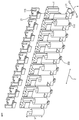
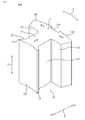
- FIG. 3 is a perspective view showing a state in which the yoke portion of the stator core of the stator shown in FIG. 1 is linearly deformed.
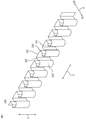
- FIG. 3 is a perspective view showing a state in which the yoke portion of the stator core of the stator shown in FIG. 1 is deformed in an annular shape and does not absorb the extra length of the crossover.
- FIG. 3 is a perspective view which shows the structure of two kinds of core plates of the stator core of the stator shown in FIG.
- FIG. 3 is a perspective view showing a configuration of a stator core in which a plurality of two types of core plates shown in FIG.
- FIG. 4 are laminated in the axial direction. It is a top view which shows the structure of the core part including one tooth of the stator core shown in FIG. It is a perspective view which showed the structure of the 1st winding frame of the stator shown in FIG. It is a perspective view which showed the structure of the 2nd winding frame of the stator shown in FIG. It is a perspective view which shows the structure which attached the 1st winding frame shown in FIG. 7 and the 2nd winding frame shown in FIG. 8 to the core part shown in FIG. It is a front view which shows the structure which looked at the core part shown in FIG. 9 from the direction indicated by the arrow A. It is a side view which shows the structure which looked at the core part shown in FIG.
- FIG. 9 is a plan view showing a configuration of the core portion shown in FIG. 9 as viewed from the direction indicated by the arrow C. It is a figure which shows the manufacturing method of the stator shown in FIG. It is a figure which shows the manufacturing method of the stator shown in FIG. It is a figure which shows the manufacturing method of the stator shown in FIG. It is a figure which shows the manufacturing method of the stator shown in FIG. It is a figure which shows the manufacturing method of the stator shown in FIG. It is a figure which shows the manufacturing method of the stator shown in FIG. It is a figure which shows the other manufacturing method of the stator shown in FIG. FIG.
- FIG. 5 is a perspective view showing a state in which the yoke portion of the stator core of the stator of the rotary electric machine in the second embodiment is linearly deformed. It is an exploded perspective view which shows the state before mounting the 1st winding frame, the 2nd winding frame, and the film part on the stator shown in FIG. It is a perspective view which shows the structure of the film part shown in FIG.
- FIG. 19 is a perspective view showing a state in which the configuration of the first winding frame shown in FIG. 19 is viewed from the upper surface side in the axial direction.
- FIG. 19 is a perspective view showing a state in which the configuration of the first winding frame shown in FIG. 19 is viewed from the lower surface side in the axial direction.
- FIG. 3 is a schematic cross-sectional view of the configuration of a rotary electric machine using the stator shown in FIG. 1 in the radial direction. It is sectional drawing which shows the structure of the rotary electric machine using the stator shown in FIG. 1 in the axial direction.
- FIG. 3 is a schematic cross-sectional view of the configuration of a rotary electric machine using the stator shown in FIG. 1 in the radial direction.
- FIG. 33 shows the manufacturing method of the stator shown in FIG. It is a perspective view which shows the structure of the stator core of the stator of the rotary electric machine in Embodiment 3.
- FIG. It is an enlarged plan view which shows the structure of the main part of the stator core shown in FIG.
- FIG. It is a perspective view which shows the structure of the split core part of the stator core of the stator of the rotary electric machine in Embodiment 4.
- FIG. It is a perspective view which showed the fixing jig of the split core part shown in FIG. 33.
- each direction in the rotary electric machine 200 is shown as a circumferential direction Z, an axial direction Y, a radial direction X, an outer X1 in the radial direction X, and an inner X2 in the radial direction X, respectively. Therefore, in the stator 100 and the rotor 102, and also in other accompanying portions, each direction will be described with reference to these directions.
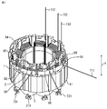
- FIG. 1 is a perspective view showing a configuration of a stator of a rotary electric machine according to the first embodiment.
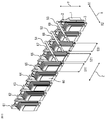
- FIG. 2 is a perspective view showing a state in which the yoke portion of the stator core of the stator shown in FIG. 1 is linearly deformed.
- FIG. 3 is a perspective view showing a state in which the yoke portion of the stator core of the stator shown in FIG. 1 is deformed in an annular shape and the extra length of the crossover is not absorbed.
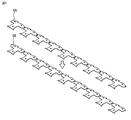
- FIG. 4 is a perspective view showing the configuration of two types of core plates of the stator core of the stator shown in FIG.
- FIG. 5 is a perspective view showing a configuration of a stator core in which a plurality of two types of core plates shown in FIG. 4 are laminated in the axial direction.
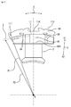
- FIG. 6 is a plan view showing the configuration of the core portion including one tooth of the stator core shown in FIG.
- FIG. 7 is a perspective view showing the configuration of the first winding frame of the stator shown in FIG.
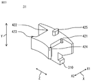
- FIG. 8 is a perspective view showing the configuration of the second winding frame of the stator shown in FIG.
- FIG. 9 is a perspective view showing a configuration in which the first winding frame shown in FIG. 7 and the second winding frame shown in FIG. 8 are attached to the core portion shown in FIG.
- FIG. 10 is a front view showing a configuration in which the core portion shown in FIG. 9 is viewed from the direction indicated by the arrow A.
- FIG. 11 is a side view showing a configuration in which the core portion shown in FIG. 9 is viewed from the direction indicated by the arrow B.
- FIG. 12 is a plan view showing the configuration of the core portion shown in FIG. 9 as viewed from the direction indicated by the arrow C.
- FIG. 13 to 17, 29, and 30 are views showing the method for manufacturing the stator shown in FIG.
- FIG. 18 is a diagram showing another manufacturing method of the stator shown in FIG.
- FIG. 24 is a schematic cross-sectional view of the configuration of the rotary electric machine using the stator shown in FIG. 1 in the radial direction.
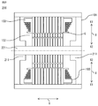
- FIG. 25 is a schematic cross-sectional view in the axial direction showing the configuration of a rotary electric machine using the stator shown in FIG.
- FIG. 26 is a flowchart showing a manufacturing method of the rotary electric machine shown in FIG. 24.
- FIG. 27 is a flowchart showing the formation of a coil in the method of manufacturing a rotary electric machine shown in FIG. 26.
- FIG. 28 is a flowchart showing the formation of a crossover of the method of manufacturing a rotary electric machine shown in FIG. 26.
- the rotary electric machine 200 includes a stator 100, a rotor 102, and a housing 101.
- the housing 101 houses the stator 100 and the rotor 102 inside.
- the rotor 102 is arranged with a predetermined gap (air gap) G provided on the inner peripheral side of the stator 100.
- the rotor 102 includes a shaft 221 and a rotor core 223.
- the shaft 221 is fitted to the inner ring of the bearing 211 provided in the housing 101 and is rotatably held.
- the rotor core 223 is fixed to the outer circumference of the shaft 221 and the permanent magnet 222 is embedded in a V shape.
- the arrangement direction of the permanent magnet 222 is not limited to the V shape, and may be a linear shape or an arrangement direction in another shape.
- the permanent magnet 222 may not be embedded in the rotor core 223, and may be attached to the outer peripheral surface of the rotor core 223 and arranged so as to face the stator 100.
- the number of magnetic poles generated by the permanent magnet 222 is not limited to 6 poles as shown in FIG. 24, and is appropriately set according to the number of teeth 12 described later in the stator 100.
- the magnetic poles The number may be ((3 ⁇ 1) ⁇ N).
- the method of continuously winding 3 teeth to the adjacent teeth 12 in the circumferential direction UU'UVV'VWW'W .
- the 1st and 3rd teeth are used. Reverse rotation winding is required.
- the number of magnetic poles may be 8 (9 ⁇ 1) / N.
- the number of teeth 12 is 6.N (N is 1 or more).
- the number of magnetic poles may be (6 ⁇ 1) 5.N.
- N is 2 or more, it is necessary to wind two teeth continuously in the circumferential direction Z and then wind the next teeth 12 four teeth apart in the circumferential direction Z, so that the winding is in the circumferential direction Z.
- a crossover operation 4 teeth away is required.
- the rotary electric machine 200 can be configured in the same manner as in the first embodiment, and therefore the description thereof will be omitted as appropriate.
- stator 100 of such a rotary electric machine 200 will be described.
- FIG. 2 when the yoke portion 11 of the stator core 1 of the stator 100 is deformed linearly, or when the yoke portion 11 is deformed into a reverse warp shape in which the protruding direction of the teeth 12 is reversed. Even so, each direction will be described in each drawing with reference to the direction of the state when the yoke portion 11 of the stator 100 is arranged in an annular shape. In addition, in other embodiments, the direction is illustrated and described with the same reference.
- the stator 100 includes the stator core 1, the coil 7, the first winding frame 2 on the upper side in the axial direction Y as an insulating portion arranged to insulate the stator core 1 and the coil 7, and the first winding frame 2.
- a second winding frame 3 on the lower side in the axial direction Y is provided.
- the stator core 1 is provided on the inner peripheral surface 112 (see FIG. 6) of the yoke portion 11 arranged in an annular shape and the inner peripheral surface 112 (see FIG. 6) of the inner side X2 of the yoke portion 11 in the radial direction X at a predetermined distance in the circumferential direction X. It has a plurality of teeth 12 (see FIG. 6) formed so as to project from the inside X2 of the.
- the stator core 1 is formed by alternately stacking a plurality of two types of core plates 6A and 6B formed by punching a thin magnetic steel plate shown in FIG. 4 in the axial direction Y as shown in FIG. As a result, the stator core 1 is formed by connecting the yoke portions 11 of the first core portion 61 to the ninth core portion 69 by the connecting portions 111 provided at the ends in the circumferential direction Z.
- the stator core 1 is configured by nine first core portions 61 to 69 being linearly connected by a connecting portion 111.
- a portion of the yoke portion 11 having one tooth 12 will be described below as a core portion 60.
- the core portion 60 includes a yoke portion 11 and a teeth 12.
- the yoke portion 11 has an outer peripheral surface 113 along the axial direction Y of the outer side X1 in the radial direction X.
- a first recess 114 extending in the axial direction Y is formed on the outer peripheral surface 113 of the yoke portion 11.
- the first recess 114 is used for positioning when the stator core 1 is attached to the winding machine forming the coil 7.
- the yoke portion 11 has an inner peripheral surface 112 along the axial direction Y of the inner side X2 in the radial direction X.
- the teeth 12 are provided on the inner peripheral surface 112 of the yoke portion 11. Further, the teeth 12 are provided with shoe portions 13 protruding in the circumferential direction Z at the tips of the inner X2 in the radial direction X.
- the stator core 1 is formed by connecting the yoke portions 11 of the plurality of core portions 60 at the connecting portion 111 in the circumferential direction Z.
- the stator core 1 is configured by connecting nine core portions 60 with a connecting portion 111.
- the yoke portion 11 of the stator core 1 can be freely bent at the connecting portion 111, whereby the yoke portion 11 can be deformed into a straight line or a reverse warp shape in which the direction of protrusion in the radial direction X of the teeth 12 is reversed. Will be done.
- the core portions 60 arranged in the circumferential direction Z are arranged from the winding start side of the coil wire 70 to the first core portion 61, the second core portion 62, and the third core portion 63.
- it is a connection structure of a star connection or a delta connection, which is composed of three phases of U phase, V phase, and W phase, and different phases are arranged for each adjacent core portion 60 in the circumferential direction Z. In all figures, the case of star connection is shown.
- the first core portion 61 is the U phase (U1)
- the second core portion 62 is the V phase (V1)
- the third core portion 63 is the W phase (W1)
- the fourth core portion 64 Is the U phase (U2)
- the fifth core portion 65 is the V phase (V2)
- the sixth core portion 66 is the W phase (W2)
- the seventh core portion 67 is the U phase (U3)
- the eighth core portion 68 is V.
- the phase (V3) and the ninth core portion 69 are the W phase (W3).
- the coil 7, the first winding frame 2 on the upper side in the axial direction Y as the insulating portion, and the second winding frame 3 on the lower side in the axial direction Y are similarly installed.
- the coil 7, the first winding frame 2 on the upper side in the axial direction Y as an insulating portion, and the second winding frame 3 on the lower side in the axial direction Y are installed in the core portion 60. Or, the description is adopted regardless of the state where it is not installed.
- the first winding frame 2 on the upper side in the axial direction Y and the second winding frame 3 on the lower side in the axial direction Y as insulating portions will be described with reference to FIGS. 7 to 12.
- the first winding frame 2 on the upper side in the axial direction Y is composed of a first protruding portion 21 and a first leg portion 22.
- the second winding frame 3 on the lower side in the axial direction Y is composed of a second protruding portion 31 and a second leg portion 32.
- FIG. 9 is a diagram showing a state in which the first winding frame 2 on the upper side in the axial direction Y and the second winding frame 3 on the lower side in the axial direction Y are installed on the core portion 60, and the first protruding portion 21 is the core portion. It is formed so as to project from one side in the axial direction Y from 60. Further, the second protruding portion 31 is formed so as to protrude from the other side in the axial direction Y from the core portion 60.
- a groove portion having a plurality of steps in the axial direction Y is formed on the outer peripheral surface of the outer side X1 of the first protrusion 21 in the radial direction X.
- the groove portion is formed by three stages of the first groove portion 91, the second groove portion 92, and the third groove portion 93 from the side separated from the stator core 1 in the axial direction Y.
- Each groove 91, 92, 93 is formed parallel to the circumferential direction Z.
- the first groove portion 91 of the first core portion 61, the first groove portion 91 of the second core portion 62 adjacent to the circumferential direction Z, and the first groove portion 91 of the third core portion 63 are It is formed to be parallel.
- the groove portions 91, 92, and 93 are not parallel to the circumferential direction Z but are formed diagonally in the circumferential direction Z. In that case, an insulating portion common to all teeth 12 can be used.
- the crossover wire 8 is a continuous line between the coils 7.
- the introduction groove portion 94 is held for introducing the coil wire 70 from the outer side X1 in the radial direction X to the inner side X2 in the radial direction X in order to wind the coil wire 70 around the teeth 12.
- the lead-out groove portion 95 holds the crossover wire 8 after winding around the teeth 12 to form the coil 7 in order to lead out from the inner side X2 of the stator core 1 in the radial direction X to the outer side X1 in the radial direction X.
- the lead-out groove portion 95 formed in the first protruding portion 21 of the first winding frame 2 on the upper side in the axial direction Y is connected to the first groove portion 91 provided on the left side of the circumferential direction Z of the lead-out groove portion 95 in FIG.
- the heights are the same in the axial direction Y.
- the first protruding portion 21 of the first winding frame 2 has a molded recess 96 having a concave shape on the inner side X2 in the radial direction X in the central portion in the circumferential direction Z (see FIG. 30). ..
- the molding recess 96 has an inner bottom portion 960 on the inner side X2 in the radial direction X.
- the forming recess 96 accommodates the extra length generated in the crossover wire 8 when the stator core 1 is deformed from the linear state at the time of winding to the annular state to be connected. Further, the crossover line 8 is held apart from the inner bottom portion 960 of the molding recess 96.
- the molding recess 96 needs to have a depth H of a concave shape on the inner side X2 in the radial direction X that can absorb the extra length S of the crossover line 8, that is, a depth H up to the inner bottom portion 960.
- the depth H of the inner bottom portion 960 will be described later.
- the second winding frame 3 on the lower side in the axial direction Y is provided with a entwining portion 310 in which the coil wire 70 at the end of winding of each coil 7 is entwined in the second protruding portion 31 in order to prevent the coil wire 70 from loosening. ..
- the first leg portion 22 of the first winding frame 2 and the second leg portion 32 of the second winding frame 3 are configured to cover the inner peripheral surface 112, the first side surface 121, and the second side surface 131 of the core portion 60. .. That is, the legs 22 and 32 are fitted in the slot 14 to insulate the coil 7 and the stator core 1.
- the lengths of the first leg portion 22 and the second leg portion 32 in the axial direction Y are formed to have substantially the same length, but the present invention is limited to this. It suffices that the stator core 1 and the coil 7 can be insulated from each other by the legs 22 and 32, and the length of each leg 22 and 32 in the axial direction Y can be appropriately changed.
- the coil wire 70 is a wire for forming the coil 7.
- the three coil wires 70 of the first coil wire 71, the second coil wire 72, and the third coil wire 73 are used.
- the wires that start the winding of the coil 7 are referred to as the first winding start wire 711, the second winding start wire 721, and the third winding start wire 731.
- first volume start line 711, the second volume start line 721, and the third volume start line 731 are moved from the outer side X1 in the radial direction X of the stator core 1 to the inner side X2 and used as a power line
- first The first power line 713, the second power line 723, and the third power line 733 are used.
- the wires for which the winding of the coil 7 has been completed are referred to as the first volume ending line 712, the second volume ending line 722, and the third volume ending line 732.
- the final line 712 of the first volume, the final line 722 of the second volume, and the final line 732 of the third volume are connected to form a neutral point.
- the coil wire 70 will be generically described.
- the crossover wire 8 is formed of a coil wire 70.
- the crossover 8 includes a first crossover 81, a second crossover 82, a third crossover 83, a fourth crossover 84, a fifth crossover 85, and a sixth crossover 86.
- the first crossover 81 connects the coil 7 of the first core portion 61 and the coil 7 of the fourth core portion 64 separated by three in the circumferential direction Z.
- the second crossover 82 connects the coil 7 of the second core portion 62 and the coil 7 of the fifth core portion 65 separated by three in the circumferential direction Z.
- the third crossover line 83 connects the coil 7 of the third core portion 63 and the coil 7 of the sixth core portion 66 separated by three in the circumferential direction Z.
- the fourth crossover line 84 connects the coil 7 of the fourth core portion 64 and the coil 7 of the seventh core portion 67.
- the fifth crossover 85 connects the coil 7 of the fifth core portion 65 and the coil 7 of the eighth core portion 68 which is separated by three in the circumferential direction Z.
- the sixth crossover 86 connects the coil 7 of the sixth core portion 66 and the coil 7 of the ninth core portion 69 separated by three in the circumferential direction Z. As shown above, when it is not necessary to explain each part of the crossover line 8, the crossover line 8 will be generically described.
- the method of manufacturing the stator of the rotary electric machine and the method of manufacturing the rotary electric machine according to the first embodiment configured as described above will be described with reference to the flowcharts of FIGS. 26 to 28.
- the magnetic steel plate is punched out to form two types of core plates 6A and 6B as shown in FIG.
- a plurality of the formed two types of core plates 6A and 6B are alternately laminated in the axial direction Y and connected by the connecting portion 111 of the yoke portion 11 to form the stator core 1 as shown in FIG. 5 ( Step ST1) in FIG. 26.
- the first winding frame 2 on the upper side in the axial direction Y and the second winding frame 3 on the lower side in the axial direction Y are formed by, for example, injection molding of an insulating resin.
- the second leg portion 32 of the above is inserted and fitted, and is attached to the stator core 1 as shown in FIG. 9 (step ST2 in FIG. 26).
- the process of forming the coil 7 (step ST3 in FIG. 26) will be described with reference to FIG. 27.
- the first coil wire 71 is introduced from the outer side X1 to the inner side X2 in the radial direction X by using the introduction groove portion 94 of the first core portion 61.
- the second coil wire 72 and the third coil wire 73 are also introduced from the outer side X1 to the inner side X2 in the radial direction X by using the introduction groove portions 94 of the second core portion 62 and the third core portion 63, respectively. do.
- FIG. 13 illustrates an example of winding around the 7th core portion 67, the 8th core portion 68, and the 9th core portion 69.
- the first coil wire 71, the second coil wire 72, and the third coil wire 73 are formed.
- the first core portion 61, the second core portion 62, and the third core portion 63 are entwined with the entwined portion 310 of the second winding frame 3 below each axial direction Y to prevent loosening.
- it is led out from the lead-out groove portion 95 from the inner side X2 in the radial direction X to the outer side X1 (FIG. 14).
- it is determined whether or not the coils 7 are formed on all the teeth 12 (step ST12 in FIG. 27).
- step ST12 becomes NO, and as shown in FIG. 14, the winding nozzles 51, 52, and 53 are moved in the direction of arrow E and the circumferential direction Z by 3 teeth to perform the next winding step.
- the first coil wire 71 is moved to the fourth core portion 64
- the second coil wire 72 is moved to the fifth core portion 65
- the third coil wire 73 is moved to the respective positions of the sixth core portion 66.
- the crossover lines 81 to 83 are housed in the grooves 91 to 93 (step ST13 in FIG. 27).
- the coil wires 71, 72, and 73 are introduced from the introduction groove portion 94 of the fourth core portion 64, the fifth core portion 65, and the sixth core portion 66 from the outer side X1 to the inner side X2 in the radial direction X.
- the coil wires 71, 72, and 73 are simultaneously wound around the teeth 12 as shown by arrows 511, 521, and 513 (step ST11 in FIG. 27).
- the first coil wire 71, the second coil wire 72, and the third coil wire 73 are formed.
- the fourth core portion 64, the fifth core portion 65, and the sixth core portion 66 are entwined with the entwined portion 310 of the second winding frame 3 below each axial direction Y to prevent loosening.
- it is led out from the lead-out groove portion 95 from the inner side X2 in the radial direction X to the outer side X1.
- it is determined whether or not the coils 7 are formed on all the teeth 12 (step ST12 in FIG. 27).
- step ST12 becomes NO, and the first coil wire 71 is the first coil wire 71 in order to move the winding nozzles 51, 52, and 53 in the direction of arrow E and the circumferential direction Z by 3 teeth to perform the next winding step.
- the second coil wire 72 is moved to the seventh core portion 67, the second coil wire 72 is moved to the eighth core portion 68, and the third coil wire 73 is moved to the respective positions of the ninth core portion 69.
- the crossover lines 84 to 86 are housed in the grooves 91 to 93 (step ST13 in FIG. 27).
- the coil wires 71, 72, and 73 are introduced from the introduction groove portion 94 of each of the seventh core portion 67, the eighth core portion 68, and the ninth core portion 69 from the outer side X1 to the inner side X2 in the radial direction X.
- the teeth of the 7th core portion 67, the 8th core portion 68, and the 9th core portion 69 are used by using the three winding nozzles 51, 52, and 53.
- the first coil wire 71, the second coil wire 72, and the third coil wire 73 are simultaneously wound around the 12 as shown by arrows 511, 521, and 513 (step ST11 in FIG. 27).
- the first coil wire 71, the second coil wire 72, and the third coil wire 73 are formed.
- the 7th core portion 67, the 8th core portion 68, and the 9th core portion 69 are entwined with the entwined portion 310 of the second winding frame 3 below the axial direction Y to prevent loosening.
- it is led out from the lead-out groove portion 95 from the inner side X2 in the radial direction X to the outer side X1.
- step ST12 it is determined whether or not the coil 7 is formed on all the teeth 12 (step ST12 in FIG. 27).
- step ST12 becomes YES, and as shown in FIG. 15, the first coil wire 71, the second coil wire 72, and the third coil wire 73 are cut, and the first winding end line 712 and the second volume end line are cut. 722, Volume 3 final line 732 is formed (step ST14 in FIG. 27). Then, the process of forming the coil is completed.
- Step ST4 in FIG. 26 will be described with reference to FIG. 28.
- the pressing portion 47 is moved from the outer side X1 to the inner side X2 in the radial direction X, and the first crossover line 81 and the fourth crossover line 84 are moved.
- each crossover line 81 to 86 has an extra length and is in a state of being separated from the first winding frame 2 to the outer side X1 in the radial direction X.
- FIGS. 17, 29, and 30 the molding portion 48 is moved from the outer side X1 in the radial direction X to the inner side X2 so that the crossover lines 81 to 86 are housed in the molding recess 96. Press and mold (step ST23 in FIG. 28). Therefore, the extra length of each crossover wire 81 to 86 is absorbed in the molding recess 96.
- FIG. 29 shows a top view of the stator core 1 after the molding. Further, FIG. 30 shows an enlarged view of the first core portion 61 of FIG. 29.
- the structure is such that the position is determined with the pressing portion 47, and the structure is such that the extra length S is stopped at a position where it can be reliably formed and at a position where the extra length S is not pushed too much.
- the timing of forming after moving the pressing portion 47 is described as after the stator core 1 is deformed into an annular state, but the timing of bending each core portion 60 is sequentially described as that of each crossover line 81 to 86. It is also possible to press the excess length into the molding recess 96 to store it, mold it, and absorb it.
- the first crossover wire 81 is formed and stored only in the molding recess 96 of the first core portion 61, and then only the second core portion 62 is bent to form a first crossover wire 81.
- the second crossover wire 82 is molded and stored only in the molding recess 96 of the 2 core portion 62, and this is sequentially repeated up to the 9th core portion 69. By doing so, it is possible to wrinkle the excess amount of the excess amount to be absorbed at the end. Then, the pressing portion 47 and the molding portion 48 are retracted and the stator 100 is discharged (step ST24 in FIG. 28).
- the first coil wire 71 thus formed is a continuous wire without being cut, and the first winding start wire 711, the coil 7 of the first core portion 61, the first crossover wire 81, and the fourth core portion 64. Coil 7, the fourth crossover wire 84, the coil 7 of the seventh core portion 67, and the first volume final wire 712.
- the second coil wire 72 is a continuous wire without being cut, and the second winding start wire 721, the coil 7 of the second core portion 62, the second crossover wire 82, the coil 7 of the fifth core portion 65, and the fifth crossover wire. 85, the coil 7 of the 8th core portion 68, and the final line 722 of the 2nd volume.
- the third coil wire 73 is a continuous wire without being cut, and is the third winding start wire 731, the coil 7 of the third core portion 63, the third crossover wire 83, the coil 7 of the sixth core portion 66, and the sixth crossover wire. 86, the coil 7 of the 9th core portion 69, and the final line 732 of the 3rd volume.
- first volume start line 711, the second volume start line 721, and the third volume start line 731 are used as power lines.
- the three first volume start lines 711, the second volume start line 721, and the third volume start line 731 need to be arranged inside X2 in the radial direction X of the stator 100 when the stator 100 is made into an annular shape. .. Therefore, as shown by the broken line in FIG. 15, the stator 100 is arranged inside X2 in the radial direction X.
- Each power line 713, 723, 733 is covered with an insulating tube on the inner side X2 in the radial direction X to maintain insulation and perform wiring processing.
- stator core 1 is made into an annular shape, and the ends of the stator core 1 are fixed to each other by welding to form the stator 100 (step ST5 in FIG. 26).
- the outer peripheral surface of the stator 100 is fixed to the inner peripheral surface of the housing 101 (step ST6 in FIG. 26).
- the bearing 211 supports the shaft 221 so that the rotor 102 can rotate in the housing 101.
- the rotor 102 is arranged to face the stator 100 via the gap G, and the rotary electric machine 200 is formed (step ST7 in FIG. 26).
- a method of linearly deforming the yoke portion 11 of the stator core 1 and winding the coil wire 70 around the teeth 12 to form the coil 7 is shown, but the present invention is not limited to this.
- a method of the above a case will be described in which the yoke portion 11 of the stator core 1 is deformed into a reverse warp shape in which the direction of protrusion in the radial direction X of the teeth is reversed by using the connecting portion 111.
- the stator 100 of the first embodiment of FIG. 18 is the same as the stator 100 of the first embodiment except that the winding method is different.
- the winding machine 400 has a hexagonal chuck mechanism 40.
- the chuck mechanism 40 has chucks 41, 42, 43, 44, 45, 46.
- Winding nozzles 54, 55, 56 for winding the coil wire 70 are installed at positions of the chuck mechanism 40 facing the chucks 41, 42, and 43.
- the winding nozzles 54, 55, and 56 are rotated around the rotation axis T, the rotation axis M, and the rotation axis N, and the coil wire 70 is wound around each tooth 12.
- FIG. 18 shows the axial direction Y reversed. That is, FIG. 18 is a diagram showing a state in which the second volume frame 3 of the core portion 60 is visible. However, the entwined portion 310 of the second winding frame 3 is not shown. Further, FIG. 18 shows a state after the coils 7 are formed in all of the core portions 61 to 69.
- the stator core 1 fixes the first core portion 61, the second core portion 62, and the third core portion 63 to the chuck 41, the chuck 42, and the chuck 43, respectively.
- the winding nozzles 54, 55, and 56 are rotated by the rotation shafts T, M, and N, and the coil wire 70 is wound around each tooth 12 to form the coil 7.
- the winding nozzles 54, 55, and 56 are moved back and forth, and the coil wire 70 is entwined with the entwining portion 310 of the second winding frame 3 on the lower side in the axial direction Y. (However, in FIG. 18, the entwined portion 310 is not shown).
- the crossover line 8 is passed over the predetermined core portion 60 in the same manner as shown above.
- the chuck mechanism 40 rotates at a pitch of 60 °. That is, the fourth core portion 64 moves by repeating the rotation of 60 ° pitch three times to the position of the chuck 41 to which the first core portion 61 is fixed in the first winding.
- the other core portion 60 also moves at the same time. Since the discharge is discharged from the position of the chuck 46, the stator core 1 is not fixed at the position of the chuck 45.
- the coil wire 70 can be wound around the teeth 12 to form the coil 7 by ensuring a wide space between the teeth 12 adjacent to each other in the circumferential direction Z. That is, as shown in FIG. 18, the rotation shafts T, M, and N of the winding nozzles 54, 55, and 56 can always be wound toward the teeth 12. Therefore, the coil wire 70 can be wound around the teeth 12 at high speed, and the winding cycle time can be shortened.
- a stator core having a plurality of teeth formed on the inner peripheral surface of the yoke portion arranged in an annular shape and the inner peripheral surface of the yoke portion in the radial direction so as to project inward in the radial direction at predetermined intervals in the circumferential direction.
- a stator of a rotary electric machine provided with a coil formed by winding a coil wire around each of the plurality of teeth, and an insulating portion disposed between the stator core and the coil to insulate the stator core and the coil.
- the insulating portion has a first protruding portion that protrudes from one side in the axial direction from the stator core.
- the first protruding portion has a groove portion having a plurality of steps in the axial direction and a molded concave portion having a concave shape in the radial direction on the outer peripheral surface of the first protruding portion in the radial direction. Since the crossover wire connecting the coils of the different teeth is a continuous wire and is held in the groove portion and the molding recess, the crossover wire is held in the groove portion and the molding recess. Since the insulation failure of the crossover can be prevented and the productivity can be improved, the cost can be reduced and the quality can be improved.
- the insulating portion has a molding recess that absorbs the extra length of the crossover wire on one side in the axial direction, and a groove portion that insulates the crossover wire of each phase and puts it in a predetermined position.
- a crossover wire is provided in the groove portion with a height difference from that of the lower stage, and the extra length of the crossover wire generated when transforming from a linear state to an annular state can be absorbed by storing it in the molding recess, so that high voltage rotation can be achieved. It is possible to prevent quality defects of crossover wires wound by continuous wires in electric machines. In addition, loosening of the coil wire during coil formation can be prevented, the number of wiring members can be reduced, the manufacturing time can be shortened, and productivity can be improved.
- the stator of the rotary electric machine described above and the rotors arranged to face the stator with a gap are provided in the housing, It is possible to prevent the crossover wire from coming into contact with the housing and short-circuiting, and it is possible to prevent poor insulation of the crossover wire.
- the coil wire is wound around the teeth to form the coil.
- the yoke portion is annularly deformed so that the teeth project inward in the radial direction, and the crossover wire is inserted into the groove portion of the first protruding portion and pressed into the molding recess to be stored. So When molding the extra length of the crossover into the molding recess, the crossover is held in the grooves of a plurality of different stages, so that the interference of the plurality of crossovers can be prevented.
- the rotor was installed in the housing through the gap in the stator manufactured by the method for manufacturing the stator of the rotary electric machine described above, the rotor was installed. Since the crossover wire is stored and held in the groove portion and the molding recess formed in the insulating portion, it is possible to prevent a short circuit with the housing due to the protrusion of the crossover wire.
- the molded recess has an inner bottom portion inside in the radial direction and has an inner bottom portion. Since the crossover is held away from the inner bottom of the molding recess, Overload on the crossover can be reduced and quality can be improved.
- the insulating portion has a second protruding portion that protrudes from the other side in the axial direction from the stator core, and the second protruding portion has a entwined portion that entangles the coil wire at the end of winding of each of the coils. So It is possible to prevent the crossover between the coils from loosening, prevent the coil from unwinding, and make the coil uniform.
- the yoke portion is formed so as to be deformable in a linear shape or in a reverse warp shape in which the direction in which the teeth project in the radial direction is reversed, the yoke portion is formed so as to be deformable.
- the coil wire can be easily wound around the teeth of the stator core.
- FIG. 19 shows a state in which the yoke portion 11 of the stator core 1 is linearly deformed in the stator of the rotary electric machine according to the second embodiment, and the first protruding portion 21, the second protruding portion 31 and the film portion 230 as insulating portions are attached.
- FIG. 20 is an exploded perspective view showing a state before the first protruding portion 21, the second protruding portion 31, and the film portion 230 shown in FIG. 19 are mounted on the stator core 1.
- FIG. 21 is a perspective view showing the configuration of the film portion 230 shown in FIG.
- FIG. 22A is a perspective view showing a state in which the configuration of the first winding frame shown in FIG.
- FIG. 22B is a perspective view showing a state in which the configuration of the first winding frame shown in FIG. 19 is viewed from the lower surface side in the axial direction.
- FIG. 23 is a perspective view showing the configuration of the second protrusion 31 shown in FIG.
- the stator 100 of the second embodiment has a different configuration of an insulating portion that insulates the stator core 1 and the coil 7 shown in the first embodiment.
- the insulating portion in order to insulate the stator core 1 and the coil 7, includes the first protruding portion 21 on the upper side in the axial direction Y, the second protruding portion 31 on the lower side in the axial direction Y, and the film. It is composed of a unit 230.
- the first winding frame 2 on the upper side in the axial direction Y of the second embodiment has only the first protruding portion 21 and does not have the first leg portion 22 of the first embodiment.
- the second winding frame 3 on the lower side in the axial direction Y has only the second protruding portion 31 and does not have the second leg portion 32 of the first embodiment.
- the first protruding portion 21 includes claw portions 411, 421, 413, 414 for fixing the film portion 230, which will be described later.
- the second protruding portion 31 includes claw portions 421, 422, 423, and 424 for fixing the film portion 230.
- the first protruding portion 21 and the second protruding portion 31 are provided with convex portions 415 and 425 for determining the position with the stator core 1, respectively.
- the stator core 1 is provided with second recesses 115 at both ends of the tooth 12 in the axial direction Y.
- the protrusions 415 and 425 are fitted and installed in the second recess 115 of the stator core 1, respectively.
- the film portion 230 is formed of a thin-walled insulating film material, and it is conceivable to use, for example, a film material having a thickness of 0.125 mm. Then, the film material is formed by making creases in the shape as shown in FIG. Due to this crease, the film portion 230 has the first side surface 231 covering the inner peripheral surface 112 along the axial direction Y of the inner side X2 of the yoke portion 11 in the radial direction X, the first side surface 121 along the axial direction Y of the teeth 12, and the first side surface 121.
- a second side surface 232 that covers the second side surface 131 along the axial direction Y of the shoe portion 13 and a third side surface 233 that covers the tip surface 122 along the axial direction Y of the teeth 12 are provided.
- the film portion 230 when the film portion 230 is attached to the stator core 1, it is connected to the first protruding portion 21 and the second protruding portion 31 in the axial direction Y. Further, the film portion 230 is continuously formed corresponding to all of the core portions 61 to 69 of the stator core 1. After the coil 7 is wound around the teeth 12, the central portion of the third side surface 233 of the film portion 230 in the circumferential direction Z is cut along the axial direction Y, and the coil 7 covers the side surface of the coil 7 in the circumferential direction Z. It can be folded in between.
- the other configurations and the method for manufacturing the stator of the rotary electric machine are the same as those in the first embodiment.
- the insulating portion includes a second protruding portion protruding from the other end side in the axial direction from the stator core, and a second protruding portion. Since it is provided with a film portion that is axially connected to the first protrusion and the second protrusion and that covers the axial side surface of the tooth and the radial inner axial side surface of the yoke portion.
- the insulating part can be formed of a thin film part.
- Embodiment 3 The stator of the rotary electric machine of the third embodiment has a configuration different from that of the stator core of each of the above embodiments. Therefore, since it is the same as each of the above-described embodiments except that the configuration of the stator core is different, a part different from each of the above-described embodiments will be mainly described.
- FIG. 31 is a perspective view showing the configuration of the stator core of the stator of the rotary electric machine according to the third embodiment.
- FIG. 32 is an enlarged plan view showing the configuration of the main part of the stator core shown in FIG. 31.
- the same parts as those in the above embodiments are designated by the same reference numerals and the description thereof will be omitted.
- the yoke portion 11 includes a thin-walled connecting portion 152 between the teeth 12 adjacent to the circumferential direction Z. Therefore, the core portions 60 are connected to each other by the thin-walled connecting portion 152.
- stator core 1 of each of the above-described embodiments has the yoke portions 11 and the core portions 60 adjacent to each other in the circumferential direction Z.
- stator core 1 of the third embodiment is connected by the rotatable connecting portion 111, whereas the core portions 60 are connected by the bendable thin-walled connecting portion 152.
- stator core 1 of each of the above embodiments two types of core plates 6A and 6B formed by punching a thin magnetic steel plate are alternately laminated in the axial direction Y, and the connecting portion 111 is formed.
- a plurality of core plates 6C of one type formed by punching a thin magnetic steel plate are laminated in the axial direction Y.
- the core plate 6C is formed so that the portions to be laminated to form the yoke portions 11 are arranged in a straight line, that is, the teeth 12 are arranged in parallel, and the yoke portions 11 adjacent to each other in the circumferential direction Z are formed. , Not physically separated, but connected by a thin-walled connecting portion 152. Therefore, by simply stacking a plurality of one type of core plates 6C in the axial direction Y, the adjacent core portions 60 can be connected and formed by the thin-walled connecting portion 152.
- the yoke portions 11 of each core portion 60 are maintained in a linearly aligned state.
- the stator 100 of the third embodiment includes an insulating portion similar to that of each of the above-described embodiments. After completing the winding on each tooth 12, the thin-walled connecting portion 152 is plastically deformed and bent so that the yoke portion 11 is annular. At this time, the positional relationship between the yoke portion 11 and each tooth 12 is the same as in each of the above-described embodiments.
- stator of the rotary electric machine of the third embodiment configured as described above, similarly to each of the above-described embodiments, A stator core having a plurality of teeth formed on the inner peripheral surface of the yoke portion arranged in an annular shape and the inner peripheral surface of the yoke portion in the radial direction so as to project inward in the radial direction at predetermined intervals in the circumferential direction. And a stator of a rotary electric machine provided with a coil formed by winding a coil wire around each of the plurality of teeth, and an insulating portion disposed between the stator core and the coil to insulate the stator core and the coil.
- the insulating portion has a first protruding portion that protrudes from one side in the axial direction from the stator core.
- the first protruding portion has a groove portion having a plurality of steps in the axial direction and a molded concave portion having a concave shape in the radial direction on the outer peripheral surface of the first protruding portion in the radial direction. Since the crossover wire connecting the coils of the different teeth is a continuous wire and is held in the groove portion and the molding recess, the crossover wire is held in the groove portion and the molding recess. Since the insulation failure of the crossover can be prevented and the productivity can be improved, the cost can be reduced and the quality can be improved.
- the insulating portion has a molding recess that absorbs the extra length of the crossover wire on one side in the axial direction, and a groove portion that insulates the crossover wire of each phase and puts it in a predetermined position.
- a crossover is applied to the groove part with a height difference from the lower stage, and the extra length of the crossover generated when transforming from a linear state to an annular state can be absorbed by storing it in the molding recess, so high voltage rotation It is possible to prevent quality defects of crossover wires wound by continuous wires in electric machines.
- loosening of the coil wire during coil formation can be prevented, the number of wiring members can be reduced, the manufacturing time can be shortened, and productivity can be improved.
- the stator of the rotary electric machine described above and the rotors arranged to face the stator with a gap are provided in the housing, It is possible to prevent the crossover wire from coming into contact with the housing and short-circuiting, and it is possible to prevent poor insulation of the crossover wire.
- the coil wire is wound around the teeth to form the coil.
- the yoke portion is annularly deformed so that the teeth project inward in the radial direction, and the crossover wire is inserted into the groove portion of the first protruding portion and pressed into the molding recess to be stored. So When molding the extra length of the crossover into the molding recess, the crossover is held in the grooves of a plurality of different stages, so that the interference of the plurality of crossovers can be prevented.
- the rotor was installed in the housing through the gap in the stator manufactured by the method for manufacturing the stator of the rotary electric machine described above, the rotor was installed. Since the crossover wire is stored and held in the groove portion and the molding recess formed in the insulating portion, it is possible to prevent a short circuit with the housing due to the protrusion of the crossover wire.
- the molded recess has an inner bottom portion inside in the radial direction and has an inner bottom portion. Since the crossover is held away from the inner bottom of the molding recess, Overload on the crossover can be reduced and quality can be improved.
- the insulating portion has a second protruding portion that protrudes from the other side in the axial direction from the stator core, and the second protruding portion has a entwined portion that entangles the coil wire at the end of winding of each of the coils. So It is possible to prevent the crossover between the coils from loosening, prevent the coil from unwinding, and make the coil uniform.
- the yoke portion is provided with a thin-walled connecting portion between the teeth adjacent in the circumferential direction, the yoke portion is provided. It can be easily formed by plastic deformation of the thin-walled connecting portion.
- the yoke portion is formed so as to be deformable in a linear shape or in a reverse warp shape in which the direction in which the teeth project in the radial direction is reversed, the yoke portion is formed so as to be deformable.
- the coil wire can be easily wound around the teeth of the stator core.
- Embodiment 4 The stator of the rotary electric machine of the fourth embodiment has a different configuration from the stator cores of the first and second embodiments. Therefore, since it is the same as the first and second embodiments except that the configuration of the stator core is different, the parts different from the first and second embodiments will be mainly described.
- FIG. 33 is a perspective view showing the configuration of the split core portion of the stator core of the stator of the rotary electric machine according to the fourth embodiment.
- FIG. 34 is a perspective view showing the fixing jig of the split core portion shown in FIG. 33.
- the same parts as those in the above embodiments are designated by the same reference numerals and the description thereof will be omitted.
- the divided core portion 600 is formed by dividing the yoke portion 11 into each tooth 12 adjacent to the circumferential direction Z.
- the divided core portion 600 corresponds to the core portion 60 of the first and second embodiments.
- stator core 1 of the first and second embodiments differs from the stator core 1 of the fourth embodiment.
- the yoke portion 11 of the stator core 1 of the first and second embodiments is adjacent to the circumferential direction Z.
- the core portions 60 are connected to each other by the rotatable connecting portion 111, whereas the stator core 1 of the fourth embodiment is not connected to the divided core portions 600 and is independent of each other. Is formed.
- stator core 1 of the first and second embodiments two types of core plates 6A and 6B formed by punching a thin magnetic steel plate are alternately laminated in the axial direction Y to form a connecting portion.
- the divided core portion 600 is formed by laminating a plurality of one type of core plate 6D formed by punching a thin magnetic steel plate in the axial direction Y. ..
- the stator core 1 of the fourth embodiment is composed of nine independent divided core portions 600.
- the stator 100 of the fourth embodiment is provided with the same insulating portions as those of the first and second embodiments.
- all the split core portions 600 are arranged and held on the fixing jig 17 so that the yoke portions 11 are arranged in a straight line, and the above-described first embodiment 1 The same winding as in is continuously performed.
- the fixing jig 17 is removed, the yoke portions 11 of the split core portions 600 are combined so as to form an annular shape, and the split core portions 600 adjacent to each other in the circumferential direction Z are fixed to each other to form the stator 100.
- welding, shrink fitting, etc. can be considered.
- stator of the rotary electric machine of the fourth embodiment configured as described above, similarly to each of the above-described embodiments, A stator core having a plurality of teeth formed on the inner peripheral surface of the yoke portion arranged in an annular shape and the inner peripheral surface of the yoke portion in the radial direction so as to project inward in the radial direction at predetermined intervals in the circumferential direction. And a stator of a rotary electric machine provided with a coil formed by winding a coil wire around each of the plurality of teeth, and an insulating portion disposed between the stator core and the coil to insulate the stator core and the coil.
- the insulating portion has a first protruding portion that protrudes from one side in the axial direction from the stator core.
- the first protruding portion has a groove portion having a plurality of steps in the axial direction and a molded concave portion having a concave shape in the radial direction on the outer peripheral surface of the first protruding portion in the radial direction. Since the crossover wire connecting the coils of the different teeth is a continuous wire and is held in the groove portion and the molding recess, the crossover wire is held in the groove portion and the molding recess. Since the insulation failure of the crossover can be prevented and the productivity can be improved, the cost can be reduced and the quality can be improved.
- the insulating portion has a molding recess that absorbs the extra length of the crossover wire on one side in the axial direction, and a groove portion that insulates the crossover wire of each phase and puts it in a predetermined position.
- a crossover wire is provided in the groove portion with a height difference from that of the lower stage, and the extra length of the crossover wire generated when transforming from a linear state to an annular state can be absorbed by storing it in the molding recess, so that high voltage rotation can be achieved. It is possible to prevent quality defects of crossover wires wound by continuous wires in electric machines. In addition, loosening of the coil wire during coil formation can be prevented, the number of wiring members can be reduced, the manufacturing time can be shortened, and productivity can be improved.
- the stator of the rotary electric machine described above and the rotors arranged to face the stator with a gap are provided in the housing, It is possible to prevent the crossover wire from coming into contact with the housing and short-circuiting, and it is possible to prevent poor insulation of the crossover wire.
- the coil wire is wound around the teeth to form the coil.
- the yoke portion is annularly deformed so that the teeth project inward in the radial direction, and the crossover wire is inserted into the groove portion of the first protruding portion and pressed into the molding recess to be stored. So When molding the extra length of the crossover into the molding recess, the crossover is held in the grooves of a plurality of different stages, so that the interference of the plurality of crossovers can be prevented.
- the rotor was installed in the housing through the gap in the stator manufactured by the method for manufacturing the stator of the rotary electric machine described above, the rotor was installed. Since the crossover wire is stored and held in the groove portion and the molding recess formed in the insulating portion, it is possible to prevent a short circuit with the housing due to the protrusion of the crossover wire.
- the molded recess has an inner bottom portion inside in the radial direction and has an inner bottom portion. Since the crossover is held away from the inner bottom of the molding recess, Overload on the crossover can be reduced and quality can be improved.
- the insulating portion has a second protruding portion that protrudes from the other side in the axial direction from the stator core, and the second protruding portion has a entwined portion that entangles the coil wire at the end of winding of each of the coils. So It is possible to prevent the crossover between the coils from loosening, prevent the coil from unwinding, and make the coil uniform.
- the yoke portion is divided and formed for each of the teeth adjacent in the circumferential direction, The yoke portion can be easily changed to a straight line.
- the yoke portion is formed so as to be deformable in a linear shape or in a reverse warp shape in which the direction in which the teeth project in the radial direction is reversed, the yoke portion is formed so as to be deformable.
- the coil wire can be easily wound around the teeth of the stator core.
- stator core 100 stator, 101 housing, 102 rotor, 11 yoke part, 111 connecting part, 112 inner peripheral surface, 113 outer peripheral surface, 114 first recess, 115 second recess, 12 teeth, 121 first side surface, 122 tip surface , 13 shoe part, 131 second side surface, 14 slot, 152 thin wall connecting part, 17 fixing jig, 2 first winding frame, 200 rotating electric machine, 21 first protruding part, 211 bearing, 22 first leg part, 221 shaft 22, Permanent magnet, 223 Rotor core, 230 Film part, 231 1st side surface, 232 2nd side surface, 233 3rd side surface, 3 2nd winding frame, 31 2nd protruding part, 310 entwined part, 32 2nd leg part, 40 chuck mechanism, 400 winding machine, 41 chuck, 42 chuck, 43 chuck, 44 chuck, 45 chuck, 46 chuck, 47 pressing part, 48 molding part, 411 claw part, 412 claw part, 413 claw part,
Landscapes
- Engineering & Computer Science (AREA)
- Power Engineering (AREA)
- Manufacturing & Machinery (AREA)
- Manufacture Of Motors, Generators (AREA)
- Iron Core Of Rotating Electric Machines (AREA)
- Insulation, Fastening Of Motor, Generator Windings (AREA)
Priority Applications (2)
| Application Number | Priority Date | Filing Date | Title |
|---|---|---|---|
| CN202080100364.0A CN115552769B (zh) | 2020-05-26 | 2020-12-09 | 旋转电机的定子、旋转电机及旋转电机的制造方法 |
| JP2022527485A JP7270846B2 (ja) | 2020-05-26 | 2020-12-09 | 回転電機のステータ、回転電機、回転電機のステータの製造方法、および回転電機の製造方法 |
Applications Claiming Priority (2)
| Application Number | Priority Date | Filing Date | Title |
|---|---|---|---|
| JP2020091012 | 2020-05-26 | ||
| JP2020-091012 | 2020-05-26 |
Publications (1)
| Publication Number | Publication Date |
|---|---|
| WO2021240849A1 true WO2021240849A1 (ja) | 2021-12-02 |
Family
ID=78744161
Family Applications (1)
| Application Number | Title | Priority Date | Filing Date |
|---|---|---|---|
| PCT/JP2020/045780 Ceased WO2021240849A1 (ja) | 2020-05-26 | 2020-12-09 | 回転電機のステータ、回転電機、回転電機のステータの製造方法、および回転電機の製造方法 |
Country Status (3)
| Country | Link |
|---|---|
| JP (1) | JP7270846B2 (https=) |
| CN (1) | CN115552769B (https=) |
| WO (1) | WO2021240849A1 (https=) |
Citations (6)
| Publication number | Priority date | Publication date | Assignee | Title |
|---|---|---|---|---|
| JP2002176753A (ja) * | 2000-12-07 | 2002-06-21 | Matsushita Electric Ind Co Ltd | 電動機固定子の製造方法及びその固定子 |
| JP2002281708A (ja) * | 2001-03-22 | 2002-09-27 | Sanyo Denki Co Ltd | 回転電機用固定子 |
| JP2009183071A (ja) * | 2008-01-31 | 2009-08-13 | Mitsubishi Electric Corp | 電動機の固定子及びそれを用いた圧縮機 |
| JP2011234562A (ja) * | 2010-04-28 | 2011-11-17 | Asmo Co Ltd | 電機子の製造方法、電機子及びモータ |
| JP2012239347A (ja) * | 2011-05-13 | 2012-12-06 | Mitsubishi Electric Corp | 回転電機およびそれに用いられるステータの製造方法 |
| JP2014217233A (ja) * | 2013-04-26 | 2014-11-17 | ダイキン工業株式会社 | モータ及び圧縮機 |
Family Cites Families (4)
| Publication number | Priority date | Publication date | Assignee | Title |
|---|---|---|---|---|
| JP5938903B2 (ja) * | 2011-12-28 | 2016-06-22 | 株式会社富士通ゼネラル | 電動機 |
| CN106489227B (zh) * | 2014-04-22 | 2019-01-22 | 三菱电机株式会社 | 电动机的定子、模制电动机和空调机 |
| JP2018198515A (ja) * | 2017-05-25 | 2018-12-13 | 三菱電機株式会社 | 回転電機の固定子の絶縁フィルム、回転電機の固定子、および固定子の製造方法 |
| JP7081211B2 (ja) * | 2018-02-28 | 2022-06-07 | 株式会社豊田自動織機 | 回転電機のステータ、及び回転電機 |
-
2020
- 2020-12-09 WO PCT/JP2020/045780 patent/WO2021240849A1/ja not_active Ceased
- 2020-12-09 CN CN202080100364.0A patent/CN115552769B/zh active Active
- 2020-12-09 JP JP2022527485A patent/JP7270846B2/ja active Active
Patent Citations (6)
| Publication number | Priority date | Publication date | Assignee | Title |
|---|---|---|---|---|
| JP2002176753A (ja) * | 2000-12-07 | 2002-06-21 | Matsushita Electric Ind Co Ltd | 電動機固定子の製造方法及びその固定子 |
| JP2002281708A (ja) * | 2001-03-22 | 2002-09-27 | Sanyo Denki Co Ltd | 回転電機用固定子 |
| JP2009183071A (ja) * | 2008-01-31 | 2009-08-13 | Mitsubishi Electric Corp | 電動機の固定子及びそれを用いた圧縮機 |
| JP2011234562A (ja) * | 2010-04-28 | 2011-11-17 | Asmo Co Ltd | 電機子の製造方法、電機子及びモータ |
| JP2012239347A (ja) * | 2011-05-13 | 2012-12-06 | Mitsubishi Electric Corp | 回転電機およびそれに用いられるステータの製造方法 |
| JP2014217233A (ja) * | 2013-04-26 | 2014-11-17 | ダイキン工業株式会社 | モータ及び圧縮機 |
Also Published As
| Publication number | Publication date |
|---|---|
| CN115552769A (zh) | 2022-12-30 |
| CN115552769B (zh) | 2025-05-06 |
| JPWO2021240849A1 (https=) | 2021-12-02 |
| JP7270846B2 (ja) | 2023-05-10 |
Similar Documents
| Publication | Publication Date | Title |
|---|---|---|
| JP7038894B2 (ja) | 回転電機のステータ、回転電機、回転電機のステータの製造方法、および、回転電機の製造方法 | |
| JP5471389B2 (ja) | 回転電機の固定子 | |
| JP2010166802A (ja) | 回転電機の固定子 | |
| US7948142B2 (en) | Stator for rotary electric machine and method of manufacturing the stator | |
| JP2011135640A (ja) | インシュレータ、回転電機および回転電機の製造方法 | |
| JP2017153261A (ja) | 回転電機、及びその製造方法 | |
| KR102869863B1 (ko) | 모터용 버스바 유닛 | |
| JP5181627B2 (ja) | 回転電機および回転電機の製造方法 | |
| JP2020110025A (ja) | セグメントコイル成形方法 | |
| JP5376028B1 (ja) | ステータ及び回転電機 | |
| JP7254140B1 (ja) | 回転電機 | |
| JP7297102B2 (ja) | 回転電機のステータ、回転電機、回転電機のステータの製造方法および、回転電機の製造方法 | |
| JP7270846B2 (ja) | 回転電機のステータ、回転電機、回転電機のステータの製造方法、および回転電機の製造方法 | |
| JP4321144B2 (ja) | コンデンサ電動機の固定子およびその製造方法 | |
| JP7455491B2 (ja) | 回転電機のステータ、回転電機、回転電機のステータの製造方法および、回転電機の製造方法 | |
| JP6968215B2 (ja) | 回転電機 | |
| JP2011160572A (ja) | 回転電機のステータの製造方法 | |
| JP5812145B2 (ja) | 回転電機の固定子 | |
| WO2023149252A1 (ja) | 回転電機のステータ、回転電機、回転電機のステータの製造方法および回転電機の製造方法 | |
| JP7774714B2 (ja) | インシュレータ、ステータ、回転電機、および、ステータの製造方法 | |
| CN121753226A (zh) | 旋转电机和旋转电机的定子 | |
| JP2004364470A (ja) | 回転電機用固定子およびその製造方法 | |
| JP2025001091A (ja) | 回転電機および回転電機の製造方法 | |
| JP7423930B2 (ja) | スロットレス回転電機、及びスロットレス回転電機の製造方法 | |
| WO2024209988A1 (ja) | 電動圧縮機用モータ、及び、その製造方法、及び、それを備えた電動圧縮機 |
Legal Events
| Date | Code | Title | Description |
|---|---|---|---|
| 121 | Ep: the epo has been informed by wipo that ep was designated in this application |
Ref document number: 20937835 Country of ref document: EP Kind code of ref document: A1 |
|
| ENP | Entry into the national phase |
Ref document number: 2022527485 Country of ref document: JP Kind code of ref document: A |
|
| NENP | Non-entry into the national phase |
Ref country code: DE |
|
| 122 | Ep: pct application non-entry in european phase |
Ref document number: 20937835 Country of ref document: EP Kind code of ref document: A1 |
|
| WWG | Wipo information: grant in national office |
Ref document number: 202080100364.0 Country of ref document: CN |