WO2021229765A1 - 刃物 - Google Patents
刃物 Download PDFInfo
- Publication number
- WO2021229765A1 WO2021229765A1 PCT/JP2020/019330 JP2020019330W WO2021229765A1 WO 2021229765 A1 WO2021229765 A1 WO 2021229765A1 JP 2020019330 W JP2020019330 W JP 2020019330W WO 2021229765 A1 WO2021229765 A1 WO 2021229765A1
- Authority
- WO
- WIPO (PCT)
- Prior art keywords
- blade
- concave
- cutting edge
- kitchen knife
- blades
- Prior art date
- Legal status (The legal status is an assumption and is not a legal conclusion. Google has not performed a legal analysis and makes no representation as to the accuracy of the status listed.)
- Ceased
Links
Images


Classifications
-
- B—PERFORMING OPERATIONS; TRANSPORTING
- B26—HAND CUTTING TOOLS; CUTTING; SEVERING
- B26B—HAND-HELD CUTTING TOOLS NOT OTHERWISE PROVIDED FOR
- B26B9/00—Blades for hand knives
- B26B9/02—Blades for hand knives characterised by the shape of the cutting edge, e.g. wavy
Definitions
- the present invention relates to a blade having a blade having a corrugated cutting edge.
- a blade of this type for example, a kitchen knife for cutting bread and a rotary mechanical blade (see, for example, Patent Document 1).
- the cutting edge portion of the kitchen knife described in Patent Document 1 is formed with a continuous corrugated cutting edge, a so-called wave blade.
- This waveform is composed of a plurality of continuous arcuate recesses.
- the angle of the blade is relatively large so that the cutting edge is not chipped when forming a plurality of concave blades constituting the wave blade. Further, as the angle of the blade is increased, the unevenness of each concave blade in the thickness direction of the kitchen knife becomes larger. Therefore, when cutting the object, that is, when moving the cutting edge, there is a problem that the contact area with the object becomes large and the frictional resistance tends to increase.
- An object of the present invention is to provide a cutting tool having a corrugated cutting edge and capable of reducing frictional resistance when cutting an object.
- the blade for achieving the above object has two surfaces located on opposite sides of each other, and also includes a blade having a corrugated cutting edge. At least one surface of the blade body has a flat portion and an inclined portion that is inclined with respect to the flat portion and forms a part of the cutting edge, and the inclined portion includes the inclined portion of the cutting edge.
- a plurality of concave blades constituting a part are provided side by side.
- the angle of the blade in the portion between the concave blades adjacent to each other is smaller than the conventional configuration in which the flat portion itself is provided with a plurality of concave blades without having the inclined portion. Become.
- the unevenness of each concave blade in the thickness direction of the blade is reduced. Therefore, when cutting the object, that is, when moving the cutting edge, the contact area with the object becomes small and the frictional resistance becomes small. Therefore, it is possible to reduce the frictional resistance when cutting an object while having a corrugated cutting edge.
- the plurality of concave blades include a plurality of types of concave blades having different shapes or sizes.
- the frictional resistance when cutting an object can be freely set by appropriately setting the arrangement pattern of a plurality of types of concave blades.
- the blade constitutes a kitchen knife.
- FIG. 2 is a cross-sectional view taken along the line 3-3 of FIG. It is a figure corresponding to FIG. 1, and is the plan view which shows the state just before forming the inclined part.
- (a) is a plan view
- (b) is a plan view showing a state immediately before forming an inclined portion.
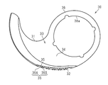
- the plan view of the rotary blade for a food processor which concerns on a modification.
- the kitchen knife 10 includes a long plate-shaped blade body 11 and a handle 18 provided at a base end portion of the blade body 11.
- the blade body 11 has a tapered shape whose width is smaller toward the tip side.
- the blade body 11 is made of a steel plate such as a stainless steel plate.
- the blade body 11 has a first surface 13 and a second surface (not shown) located on opposite sides of each other.
- the longitudinal direction of the kitchen knife 10, the width direction of the kitchen knife 10, and the thickness direction of the kitchen knife 10 will be described simply as the longitudinal direction, the width direction, and the thickness direction.
- a corrugated cutting edge 12 is provided on one edge of the blade 11 in the width direction.
- the first surface 13 of the blade body 11 has a flat portion 14 and an inclined portion 15 that is inclined with respect to the flat portion 14 and forms a part of the blade edge 12.
- the flat portion 14 extends substantially over the longitudinal direction of the blade 11. Further, the flat portion 14 extends from the base end of the cutting edge 12 to the edge of the blade body 11 opposite to the one side in the width direction.
- the inclined portion 15 is provided with a plurality of concave blades 16 constituting a part of the cutting edge 12 side by side in the longitudinal direction.
- the plurality of concave blades 16 include a plurality of types of concave blades 16A and 16B having different shapes and sizes.
- the plurality of concave blades 16 include a first concave blade 16A and a second concave blade 16B whose size in the width direction and the size in the longitudinal direction are both smaller than those of the first concave blade 16A.
- the first concave blade 16A and the second concave blade 16B are provided alternately in the longitudinal direction.
- the manufacturing method first includes a step of forming a corrugated cutting edge 22 with respect to the first surface 13 of the blade 11 on which the inclined portion 15 is not formed.
- the cutting edge 22 includes a first concave blade 26A, a first concave blade 26A, and a second concave blade 26B having a smaller width direction size and a longitudinal size than the first concave blade 26A.
- the first concave blade 26A and the second concave blade 26B are provided alternately.
- each valley portion P1 adjacent to the flat portion 14 in the first concave blade 26A and each mountain forming the cutting edge 22 in the portion 27 between the first concave blade 26A and the second concave blade 26B is included.
- the inclined portion 15 is formed.
- the kitchen knife 10 of this embodiment Compare the kitchen knife 10 of this embodiment with a conventional kitchen knife. Since the kitchen knife shown in FIG. 4 does not have the inclined portion 15 and has a configuration in which a plurality of concave blades 26A and 26B are provided on the flat portion 14 itself, it is considered to have the same configuration as a conventional kitchen knife. Can be done. As shown in FIG. 3, in the kitchen knife 10 of the present embodiment, the angle ⁇ of the blade in the portion 17 between the concave blades 16 adjacent to each other is smaller than that of the conventional kitchen knife indicated by the alternate long and short dash line. As a result, the unevenness of each concave blade 16 in the thickness direction of the blade 11 is reduced. Therefore, when cutting the object, that is, when moving the cutting edge 12, the contact area with the object becomes small and the frictional resistance becomes small.
- the first surface 13 of the blade body 11 has a flat portion 14 and an inclined portion 15 that is inclined with respect to the flat portion 14 and forms a part of the cutting edge 12.
- a plurality of concave blades 16 constituting a part of the cutting edge 12 are provided side by side on the inclined portion 15.
- the plurality of concave blades 16 include a plurality of types of concave blades 16A and 16B having different shapes and sizes.
- the frictional resistance when cutting an object can be freely set by appropriately setting the arrangement pattern of a plurality of types of concave blades 16A and 16B.
- the arrangement pattern of the first concave blade 16A and the second concave blade 16B can be changed as appropriate.
- two second concave blades 16B may be arranged between the first concave blades 16A.
- a plurality of concave blades 16 include two types of concave blades 16A and 16B having different shapes and sizes, but the plurality of concave blades have three or more types. It may include a concave blade.
- the shape of the plurality of concave blades 16 may include only one type of concave blade.
- the concave blade 16 as shown in FIG. 6A may be used.
- the corrugated cutting edge 22 is formed with respect to the first surface 13 of the blade 11.
- the cutting edge 22 is composed of a plurality of concave blades 26 having the same shape and size.
- the flat portion 14 and A part of the concave blade 26 is removed by polishing. As a result, the inclined portion 15 is formed.
- the inclined portion 15 constituting the cutting edge 12 is provided on the first surface 13 of the blade body 11, but the inclined portion 15 is also provided on the second surface opposite to the first surface 13. May be good. Further, a plurality of concave blades constituting a part of the cutting edge may be provided on the inclined portion 15 provided on the second surface.
- the knife according to the present invention is not limited to kitchen knives.
- the present invention can be applied to a rotary blade of a food processor.
- the rotary blade 30 has an annular mounting portion 38 having an insertion hole 38a into which the rotating body is inserted, and a blade body 31 extending from the mounting portion 38.
- the blade body 31 has a corrugated cutting edge 32.
- the first surface 33 of the blade body 31 has a flat portion 34 and an inclined portion 35 that is inclined with respect to the flat portion 34 and forms a part of the cutting edge 32.
- a plurality of concave blades 36 forming a part of the cutting edge 32 are provided side by side on the inclined portion 35.
- the plurality of concave blades 36 include a first concave blade 36A and a second concave blade 36B having different shapes and sizes from each other.
Landscapes
- Life Sciences & Earth Sciences (AREA)
- Forests & Forestry (AREA)
- Engineering & Computer Science (AREA)
- Mechanical Engineering (AREA)
- Knives (AREA)
Priority Applications (2)
| Application Number | Priority Date | Filing Date | Title |
|---|---|---|---|
| PCT/JP2020/019330 WO2021229765A1 (ja) | 2020-05-14 | 2020-05-14 | 刃物 |
| JP2021525767A JP7208674B2 (ja) | 2020-05-14 | 2020-05-14 | 刃物 |
Applications Claiming Priority (1)
| Application Number | Priority Date | Filing Date | Title |
|---|---|---|---|
| PCT/JP2020/019330 WO2021229765A1 (ja) | 2020-05-14 | 2020-05-14 | 刃物 |
Publications (1)
| Publication Number | Publication Date |
|---|---|
| WO2021229765A1 true WO2021229765A1 (ja) | 2021-11-18 |
Family
ID=78525552
Family Applications (1)
| Application Number | Title | Priority Date | Filing Date |
|---|---|---|---|
| PCT/JP2020/019330 Ceased WO2021229765A1 (ja) | 2020-05-14 | 2020-05-14 | 刃物 |
Country Status (2)
| Country | Link |
|---|---|
| JP (1) | JP7208674B2 (https=) |
| WO (1) | WO2021229765A1 (https=) |
Citations (5)
| Publication number | Priority date | Publication date | Assignee | Title |
|---|---|---|---|---|
| JPS58105781A (ja) * | 1981-12-12 | 1983-06-23 | ウイルキンソン・ソ−ド・リミテツド | ナイフ |
| JPS59145367U (ja) * | 1983-03-16 | 1984-09-28 | マツク株式会社 | 冷凍物用庖丁 |
| JPH04368U (https=) * | 1990-04-17 | 1992-01-06 | ||
| JP3191820U (ja) * | 2014-04-30 | 2014-07-10 | 下村工業株式会社 | パン切用ナイフ |
| JP2019063390A (ja) * | 2017-10-04 | 2019-04-25 | アーネスト株式会社 | 刃物及びその刃部 |
-
2020
- 2020-05-14 JP JP2021525767A patent/JP7208674B2/ja active Active
- 2020-05-14 WO PCT/JP2020/019330 patent/WO2021229765A1/ja not_active Ceased
Patent Citations (5)
| Publication number | Priority date | Publication date | Assignee | Title |
|---|---|---|---|---|
| JPS58105781A (ja) * | 1981-12-12 | 1983-06-23 | ウイルキンソン・ソ−ド・リミテツド | ナイフ |
| JPS59145367U (ja) * | 1983-03-16 | 1984-09-28 | マツク株式会社 | 冷凍物用庖丁 |
| JPH04368U (https=) * | 1990-04-17 | 1992-01-06 | ||
| JP3191820U (ja) * | 2014-04-30 | 2014-07-10 | 下村工業株式会社 | パン切用ナイフ |
| JP2019063390A (ja) * | 2017-10-04 | 2019-04-25 | アーネスト株式会社 | 刃物及びその刃部 |
Also Published As
| Publication number | Publication date |
|---|---|
| JPWO2021229765A1 (https=) | 2021-11-18 |
| JP7208674B2 (ja) | 2023-01-19 |
Similar Documents
| Publication | Publication Date | Title |
|---|---|---|
| US8448887B2 (en) | Food grater | |
| JP2001522733A (ja) | 帯状または短冊状のカッタ | |
| JP2005059124A (ja) | 回転鋸 | |
| US20190255717A1 (en) | Knife blade and method for making same | |
| WO2021229765A1 (ja) | 刃物 | |
| JP2002248278A (ja) | 刃 物 | |
| WO2003068465A1 (en) | Cutter | |
| CN102133056B (zh) | 食物磨碎器 | |
| JP2019063390A (ja) | 刃物及びその刃部 | |
| JP3759943B2 (ja) | ナイフ | |
| JP5184878B2 (ja) | ドリル | |
| WO2024236692A1 (ja) | 直刃包丁及び直刃包丁の製造方法 | |
| JP7402571B1 (ja) | 波刃包丁及び波刃包丁の研ぎ方法 | |
| JP3505476B2 (ja) | 丸 鋸 | |
| JP2000280374A (ja) | リード罫の形成用刃物 | |
| JP7402573B1 (ja) | 波刃包丁 | |
| CN222958683U (zh) | 刀具 | |
| TWM451230U (zh) | 刀具 | |
| WO2020084818A1 (ja) | 切断器具及びその製造方法 | |
| JP2517950Y2 (ja) | 鋸 刃 | |
| CN209255866U (zh) | 燕尾刀结构 | |
| JP2008238316A (ja) | 切削工具 | |
| JP2009196046A (ja) | 円盤形回転カッター | |
| JP4048680B2 (ja) | スローアウェイチップ | |
| JP4206690B2 (ja) | シェービングカッタ |
Legal Events
| Date | Code | Title | Description |
|---|---|---|---|
| ENP | Entry into the national phase |
Ref document number: 2021525767 Country of ref document: JP Kind code of ref document: A |
|
| 121 | Ep: the epo has been informed by wipo that ep was designated in this application |
Ref document number: 20934890 Country of ref document: EP Kind code of ref document: A1 |
|
| NENP | Non-entry into the national phase |
Ref country code: DE |
|
| 122 | Ep: pct application non-entry in european phase |
Ref document number: 20934890 Country of ref document: EP Kind code of ref document: A1 |