WO2021229738A1 - 加工機械およびスライド機構 - Google Patents
加工機械およびスライド機構 Download PDFInfo
- Publication number
- WO2021229738A1 WO2021229738A1 PCT/JP2020/019223 JP2020019223W WO2021229738A1 WO 2021229738 A1 WO2021229738 A1 WO 2021229738A1 JP 2020019223 W JP2020019223 W JP 2020019223W WO 2021229738 A1 WO2021229738 A1 WO 2021229738A1
- Authority
- WO
- WIPO (PCT)
- Prior art keywords
- door
- opening
- axis direction
- traveling wheel
- processing machine
- Prior art date
- Legal status (The legal status is an assumption and is not a legal conclusion. Google has not performed a legal analysis and makes no representation as to the accuracy of the status listed.)
- Ceased
Links
Images



Classifications
-
- B—PERFORMING OPERATIONS; TRANSPORTING
- B23—MACHINE TOOLS; METAL-WORKING NOT OTHERWISE PROVIDED FOR
- B23Q—DETAILS, COMPONENTS, OR ACCESSORIES FOR MACHINE TOOLS, e.g. ARRANGEMENTS FOR COPYING OR CONTROLLING; MACHINE TOOLS IN GENERAL CHARACTERISED BY THE CONSTRUCTION OF PARTICULAR DETAILS OR COMPONENTS; COMBINATIONS OR ASSOCIATIONS OF METAL-WORKING MACHINES, NOT DIRECTED TO A PARTICULAR RESULT
- B23Q11/00—Accessories fitted to machine tools for keeping tools or parts of the machine in good working condition or for cooling work; Safety devices specially combined with or arranged in, or specially adapted for use in connection with, machine tools
- B23Q11/08—Protective coverings for parts of machine tools; Splash guards
- B23Q11/0825—Relatively slidable coverings, e.g. telescopic
-
- B—PERFORMING OPERATIONS; TRANSPORTING
- B23—MACHINE TOOLS; METAL-WORKING NOT OTHERWISE PROVIDED FOR
- B23Q—DETAILS, COMPONENTS, OR ACCESSORIES FOR MACHINE TOOLS, e.g. ARRANGEMENTS FOR COPYING OR CONTROLLING; MACHINE TOOLS IN GENERAL CHARACTERISED BY THE CONSTRUCTION OF PARTICULAR DETAILS OR COMPONENTS; COMBINATIONS OR ASSOCIATIONS OF METAL-WORKING MACHINES, NOT DIRECTED TO A PARTICULAR RESULT
- B23Q11/00—Accessories fitted to machine tools for keeping tools or parts of the machine in good working condition or for cooling work; Safety devices specially combined with or arranged in, or specially adapted for use in connection with, machine tools
- B23Q11/08—Protective coverings for parts of machine tools; Splash guards
- B23Q11/0891—Protective coverings for parts of machine tools; Splash guards arranged between the working area and the operator
-
- B—PERFORMING OPERATIONS; TRANSPORTING
- B23—MACHINE TOOLS; METAL-WORKING NOT OTHERWISE PROVIDED FOR
- B23B—TURNING; BORING
- B23B25/00—Accessories or auxiliary equipment for turning-machines
- B23B25/04—Safety guards specially designed for turning machines
-
- B—PERFORMING OPERATIONS; TRANSPORTING
- B23—MACHINE TOOLS; METAL-WORKING NOT OTHERWISE PROVIDED FOR
- B23B—TURNING; BORING
- B23B3/00—General-purpose turning-machines or devices, e.g. centre lathes with feed rod and lead screw; Sets of turning-machines
- B23B3/06—Turning-machines or devices characterised only by the special arrangement of constructional units
- B23B3/065—Arrangements for performing other machining operations, e.g. milling, drilling
-
- E—FIXED CONSTRUCTIONS
- E05—LOCKS; KEYS; WINDOW OR DOOR FITTINGS; SAFES
- E05D—HINGES OR SUSPENSION DEVICES FOR DOORS, WINDOWS OR WINGS
- E05D15/00—Suspension arrangements for wings
- E05D15/06—Suspension arrangements for wings for wings sliding horizontally more or less in their own plane
- E05D15/0621—Details, e.g. suspension or supporting guides
-
- Y—GENERAL TAGGING OF NEW TECHNOLOGICAL DEVELOPMENTS; GENERAL TAGGING OF CROSS-SECTIONAL TECHNOLOGIES SPANNING OVER SEVERAL SECTIONS OF THE IPC; TECHNICAL SUBJECTS COVERED BY FORMER USPC CROSS-REFERENCE ART COLLECTIONS [XRACs] AND DIGESTS
- Y10—TECHNICAL SUBJECTS COVERED BY FORMER USPC
- Y10S—TECHNICAL SUBJECTS COVERED BY FORMER USPC CROSS-REFERENCE ART COLLECTIONS [XRACs] AND DIGESTS
- Y10S29/00—Metal working
- Y10S29/056—Metal working with shield or hood movements
-
- Y—GENERAL TAGGING OF NEW TECHNOLOGICAL DEVELOPMENTS; GENERAL TAGGING OF CROSS-SECTIONAL TECHNOLOGIES SPANNING OVER SEVERAL SECTIONS OF THE IPC; TECHNICAL SUBJECTS COVERED BY FORMER USPC CROSS-REFERENCE ART COLLECTIONS [XRACs] AND DIGESTS
- Y10—TECHNICAL SUBJECTS COVERED BY FORMER USPC
- Y10T—TECHNICAL SUBJECTS COVERED BY FORMER US CLASSIFICATION
- Y10T29/00—Metal working
- Y10T29/51—Plural diverse manufacturing apparatus including means for metal shaping or assembling
- Y10T29/5104—Type of machine
- Y10T29/5109—Lathe
-
- Y—GENERAL TAGGING OF NEW TECHNOLOGICAL DEVELOPMENTS; GENERAL TAGGING OF CROSS-SECTIONAL TECHNOLOGIES SPANNING OVER SEVERAL SECTIONS OF THE IPC; TECHNICAL SUBJECTS COVERED BY FORMER USPC CROSS-REFERENCE ART COLLECTIONS [XRACs] AND DIGESTS
- Y10—TECHNICAL SUBJECTS COVERED BY FORMER USPC
- Y10T—TECHNICAL SUBJECTS COVERED BY FORMER US CLASSIFICATION
- Y10T409/00—Gear cutting, milling, or planing
- Y10T409/30—Milling
- Y10T409/30392—Milling with means to protect operative or machine [e.g., guard, safety device, etc.]
Definitions
- the present invention relates to a processing machine and a slide mechanism.
- Patent Document 1 discloses a machine tool provided with an opening / closing door.
- the opening / closing door is supported by a guide rail and a door roller sliding on the guide rail so as to be slidable to the left and right.
- a processing machine provided with a door slidably supported by a rail member is known.
- the rail member may be exposed to foreign matter such as chips or cutting oil associated with machining the work in the machining area. In this case, it becomes difficult to slide the door smoothly.
- a guide rail is provided on a machine frame (base member) that slidably supports the opening / closing door.
- various problems may occur, such as the need to secure a space for providing the guide rail, which is a long body, on the base member.
- the object of the present invention is to solve the above-mentioned problems, and to provide a processing machine capable of smoothly sliding the door.
- Another object of the present invention is to provide a slide mechanism capable of solving various problems that may occur by providing a rail member on a base member that slidably supports a moving body.
- a processing machine is provided with an opening in a predetermined direction between a cover body for partitioning a processing area, a first position for opening the opening, and a second position for closing the opening.
- the first sliding door and the first door that overlaps with the first door from the inside of the processing area and opens the opening, and the first position that is opposite to the second position and the first position. It includes a second door that can slide in a predetermined direction between the door and a third position that closes the opening, and an engaging portion that engages with the first door, which is provided on the second door with respect to the first door.
- a rail member that allows the second door to slide in a predetermined direction is provided. The engaging portion is located outside the machining area.
- the engaging portion of the rail member that engages with the first door is arranged outside the machining area, so that the engaging portion is associated with the machining of the work in the machining area. It is possible to prevent exposure to foreign matter such as chips or cutting oil. As a result, the engaging portion is kept clean, so that the second door can be smoothly slid with respect to the first door.
- the second door includes an outer surface facing the first door when the first door and the second door are positioned in the first position.
- the rail member is provided on the second door so as not to protrude from the outer surface toward the first door.
- the first door and the second door can be provided closer to each other, so that the airtightness of the processing area can be improved.
- the engaging portion is arranged so as to face the first door when the first door is positioned at the second position and the second door is positioned at the third position, and is unidirectional along a predetermined direction. Includes an open end that opens toward.
- the second door further includes a door body portion provided with a rail member and a lid member attached to the door body portion and closing the opening formed by the opening end portion.
- the first door can be engaged with the engaging portion through the opening end portion when the processing machine is assembled. Further, by attaching a lid member to the door body portion and closing the opening formed by the opening end portion, it is possible to prevent foreign matter such as chips or cutting oil from entering the engaging portion.
- the lid member extends toward the first door and includes a labyrinth portion forming a labyrinth structure with the first door.
- the number of parts can be reduced by integrally providing the labyrinth portion for providing the labyrinth structure with the lid member that closes the opening formed by the opening end portion.
- the predetermined direction is the horizontal direction.
- the opening includes a front opening located in front of the machine in the machining area and an upper opening extending from the front opening and located above the machining area.
- the second door includes a front door portion that closes the front opening and an upper door portion that closes the upper opening when positioned at the third position.
- the rail member is provided on the front door portion of the front door portion and the upper door portion.
- the front door portion closes the front opening arranged in front of the machine in the processing area, so that foreign matter such as chips or cutting oil scatters toward the front door portion. easy. Therefore, by providing the rail member in the front door portion of the front door portion and the upper door portion, it is possible to more effectively prevent the rail member from being exposed to foreign matter such as chips or cutting oil.
- the slide mechanism according to the present invention is provided on the base member, a moving body that can slide in a predetermined direction, and the base member so that the moving body can slide in a predetermined direction with respect to the base member. It is provided with a matching rail member.
- FIG. 3 is a cross-sectional view showing a processing machine seen in the direction of arrow on the IV-IV line in FIG.
- FIG. 4 is a perspective view which shows the traveling wheel provided in the 1st door in FIG. 4, and the mounting structure of the traveling wheel.
- FIG. 4 is another perspective view which shows the traveling wheel provided in the 1st door in FIG. 4, and the mounting structure of the traveling wheel.
- FIG. 3 is a cross-sectional view showing a processing machine seen in the direction of arrow on the line VII-VII in FIG. It is an disassembled assembly drawing of the 2nd door shown in FIG.
- FIG. 3 is a cross-sectional view showing a processing machine seen in the direction of arrow on the IX-IX line in FIG. It is sectional drawing which shows the processing machine seen in the arrow view direction on the XX line in FIG.
- FIG. 3 is a cross-sectional view showing a processing machine seen in the direction of arrow on the XI-XI line in FIG.
- FIG. 1 is a perspective view showing a processing machine according to an embodiment of the present invention.
- FIG. 2 is a perspective view showing an open state of the first door and the second door in the processing machine in FIG. 1.
- FIG. 3 is a perspective view showing a closed state of the first door and the second door in the processing machine in FIG. 1.
- the machining machine 100 is an NC (Numerically Control) machining machine in which various operations for machining a workpiece are automated by numerical control by a computer.
- the machining machine 100 is a multi-tasking machine having a turning function using a fixed tool and a milling function using a rotary tool.
- an axis parallel to the left-right direction (width direction) of the processing machine 100 and extending in the horizontal direction is referred to as a "Z axis", and is parallel to the front-back direction (depth direction) of the processing machine 100 and is horizontal.
- the axis extending in the direction is called “Y axis”
- the axis extending in the vertical direction is called “X axis”.
- the right direction in FIG. 1 is referred to as "+ Z axis direction”
- the left direction is referred to as "-Z axis direction”.
- the front direction of the paper surface is referred to as "+ Y axis direction”
- the back direction is referred to as "-Y axis direction”.
- the upward direction in FIG. 1 is referred to as "+ X-axis direction”
- the downward direction is referred to as "-X-axis direction”.
- the X-axis, Y-axis, and Z-axis are three axes orthogonal to each
- the processing machine 100 has a cover body 21.
- the cover body 21 forms the processing area 110 and has the appearance of the processing machine 100.
- the processing area 110 is a space in which the work is processed, and is substantially sealed so that foreign matter such as chips or cutting oil associated with the work processing does not leak to the outside of the processing area 110.
- the cover body 21 is provided with an opening 50.
- the opening 50 forms an opening that allows the inside of the processing area 110 and the outside of the processing area 110 to communicate with each other. The operator can access the inside of the processing area 110 from the outside of the processing area 110 through the opening 50.
- the opening 50 has a front opening 51 and an upper opening 52.
- the front opening 51 is arranged in front of the machine (on the side in the + Y axis direction) of the machining area 110.
- the upper opening 52 is arranged above the machining area 110 (on the side in the + X axis direction).
- the upper opening 52 is continuous with the front opening 51.
- the cover body 21 has a first door 31, a second door 41, a side cover 27, and a magazine cover 26.
- the first door 31 and the second door 41 are arranged in the opening 50.
- the first door 31 is slidable in a predetermined direction between the first position J for opening the opening 50 and the second position K for closing the opening 50.
- the second door 41 is arranged so as to overlap the first door 31 from the inside of the processing area 110.
- the second door 41 is located on the opposite side of the first position J from the second position K to the first position J for opening the opening 50, and the third position for closing the opening 50 together with the first door 31. It can slide in a predetermined direction with L.
- the first door 31 and the second door 41 can slide independently of each other.
- the first door 31 and the second door 41 can slide in the same direction as each other.
- the first door 31 and the second door 41 are slidable in the horizontal direction.
- the first door 31 and the second door 41 are slidable in the Z-axis direction.
- the first door 31 and the second door 41 may be a manual door that is manually slid, or an automatic door that is slid by an actuator such as a cylinder or a motor.
- the opening 50 is closed.
- the first door 31 is arranged at a position adjacent to the second door 41 in the + Z axis direction.
- the first door 31 and the second door 41 are arranged on the left and right sides of the machine in the machining area 110, and are arranged on the inner side in the machining area 110, and the tool spindles in the X-axis direction and the Z-axis direction (not shown).
- the processing area 110 is partitioned together with the telesco cover that can be deformed with the movement of the machine, the ceiling cover that is arranged above the processing area 110, and the like.
- the first door 31 has a front door portion 32 and an upper door portion 33.
- the front door portion 32 closes the front opening 51 shown in FIG. 2, and the upper door portion 33 closes the upper opening 52 shown in FIG. To block.
- the front door portion 32 has a plate shape parallel to the X-axis-Z-axis plane as a whole.
- the front door portion 32 is provided with a transparent window 34 (see FIG. 1).
- the upper door portion 33 has a plate shape parallel to the Y-axis-Z-axis plane as a whole.
- the upper end portion of the front door portion 32 and the front end portion (end portion in the + Y axis direction) of the upper door portion 33 are connected to form a corner portion.
- the second door 41 has a front door portion 42 and an upper door portion 43.
- the front door portion 42 closes the front opening 51 shown in FIG. 2, and the upper door portion 43 closes the upper opening 52 shown in FIG. To block.
- the front door portion 42 has a plate shape parallel to the X-axis-Z-axis plane as a whole.
- the front door portion 42 is provided with a transparent window 44 (see FIG. 1).
- the upper door portion 43 has a plate shape parallel to the Y-axis-Z-axis plane as a whole.
- the upper end portion of the front door portion 42 and the front end portion (end portion in the + Y axis direction) of the upper door portion 43 are connected to form a corner portion.
- the end portion of the second door 41 in the + Z axis direction overlaps with the end portion of the first door 31 in the ⁇ Z axis direction from the inside of the machining area 110.
- the end of the front door 42 of the second door 41 in the + Z-axis direction and the end of the front door 32 of the first door 31 in the ⁇ Z-axis direction face each other in the Y-axis direction.
- the end of the upper door 43 of the second door 41 in the + Z-axis direction and the end of the upper door 33 of the first door 31 in the ⁇ Z-axis direction face each other in the X-axis direction.
- the side cover 27 and the magazine cover 26 are provided on both sides of the opening 50 in the Z-axis direction, respectively.
- the side cover 27 is provided at a position adjacent to the first door 31 positioned at the second position K in the + Z axis direction.
- a work spindle for rotating the work, a tailstock for supporting the center of rotation of the work, and the like are housed.
- the magazine cover 26 is provided at a position adjacent to the second door 41 positioned at the third position L in the ⁇ Z axis direction.
- a magazine or the like for storing a plurality of tools used for machining the work is housed.
- the opening 50 is opened.
- the first door 31 and the second door 41 are arranged inside the side cover 27.
- the processing area 110 is opened to the outside of the processing area 110 through the opened opening 50.
- the length of the second range 320 in the Z-axis direction is larger than the length of the first range 310 in the Z-axis direction shown in FIG.
- the end of the first door 31 in the ⁇ Z axis direction protrudes from the side cover 27.
- the end of the second door 41 in the ⁇ Z axis direction protrudes from the first door 31.
- FIG. 4 is a cross-sectional view showing a processing machine seen in the direction of arrow on the IV-IV line in FIG.
- the second door 41 has an outer surface 46 and an inner surface 47.
- the outer surface 46 is arranged outside the machining area 110.
- the inner surface 47 is the back side of the outer surface 46 and is arranged inside the processing area 110.
- the inner surface 47 faces the ⁇ Y axis direction, and the outer surface 46 faces the + Y axis direction.
- the outer surface 46 faces the first door 31 in the second range 320 shown in FIG.
- the outer surface 46 faces the first door 31 in the first range 310 shown in FIG. doing.
- the second door 41 has a door body portion 45.
- the door body 45 forms the main part of the second door 41 that closes the opening 50.
- the door body portion 45 is composed of a front door portion 42 and an upper door portion 43.
- the processing machine 100 further includes a rail member 61.
- the rail member 61 is provided on the second door 41.
- the rail member 61 is provided on the door body 45.
- the rail member 61 is provided on the front door portion 42.
- the rail member 61 is provided on the front door portion 42 of the front door portion 42 and the upper door portion 43.
- the rail member 61 has a long shape in which the Z-axis direction is the longitudinal direction.
- the rail member 61 is provided at a position closer to the lower end than the upper end of the front door portion 42 in the X-axis direction.
- the rail member 61 is provided on the second door 41 so as not to protrude from the outer surface 46 toward the first door 31.
- An internal space 115 is formed between the inner surface 47 and the outer surface 46.
- the rail member 61 is housed in the internal space 115.
- the second door 41 is provided with a notch 49 that opens to the outer surface 46.
- the internal space 115 and the processing area 110 are separated from each other with an inner surface 47 interposed therebetween.
- the internal space 115 is connected to the outside of the processing area 110 through the notch 49.
- the processing machine 100 has a plurality of rail members 61 (61A, 61B).
- the rail member 61A and the rail member 61B are arranged so as to face each other in the vertical direction in the internal space 115.
- the rail member 61B is provided above the rail member 61A.
- the rail member 61A is provided directly below the opening formed by the notch 49.
- the rail member 61B is provided directly above the opening formed by the notch 49.
- the rail member 61A is composed of a plate material bent along a plurality of straight lines extending in the Z-axis direction.
- the rail member 61B is composed of blocks.
- the rail member 61A has a groove portion 62.
- the groove portion 62 has a groove shape extending in the Z-axis direction.
- the groove portion 62 is open toward the + X axis direction (upward).
- the rail member 61B has a contact portion 63.
- the contact portion 63 has a planar shape extending in the Z-axis direction.
- the contact portion 63 faces in the ⁇ X axis direction (downward) and is formed of a plane parallel to the YZ axis plane.
- the groove portion 62 and the contact portion 63 are arranged outside the processing area 110.
- the groove portion 62 and the contact portion 63 are arranged in the internal space 115.
- the groove portion 62, the contact portion 63, and the processing area 110 are separated from each other with an inner surface 47 interposed therebetween.
- the groove portion 62 and the contact portion 63 correspond to the “engagement portion” in the present invention.
- FIGS. 5 and 6 are perspective views showing a traveling wheel provided on the first door in FIG. 4 and a mounting structure of the traveling wheel.
- the processing machine 100 further includes a first traveling wheel 64 (64A, 64B) and a second traveling wheel 65.
- the first traveling wheel 64 and the second traveling wheel 65 are provided on the first door 31.
- the first traveling wheel 64 and the second traveling wheel 65 are provided on the front door portion 32.
- the first traveling wheel 64 and the second traveling wheel 65 are provided at positions closer to the lower end than the upper end of the front door portion 32 in the X-axis direction.
- the first traveling wheel 64 and the second traveling wheel 65 are provided at positions closer to the end of the first door 31 in the ⁇ Z axis direction than the end of the first door 31 in the + Z axis direction in the Z axis direction.
- the first traveling wheel 64 and the second traveling wheel 65 are positioned. It is arranged in the first range 310.
- the first traveling wheel 64 and the second traveling wheel 65 are composed of, for example, a cam follower.
- the first traveling wheel 64 is provided so as to be rotatable around a rotating shaft 121 extending in the X-axis direction.
- the first traveling wheel 64A and the first traveling wheel 64B are arranged so as to be spaced apart from each other in the Z-axis direction.
- the second traveling wheel 65 is provided so as to be rotatable around a rotating shaft 122 extending in the Y-axis direction.
- the second traveling wheel 65 is provided above the first traveling wheel 64.
- the second traveling wheel 65 is provided between the first traveling wheel 64A and the first traveling wheel 64B in the Z-axis direction.
- the groove portion 62 and the contact portion 63 are engaged with the first door 31.
- the rail member 61 makes the second door 41 slidable with respect to the first door 31.
- the first traveling wheel 64 is fitted in the groove portion 62.
- the first traveling wheel 64A and the first traveling wheel 64B are fitted to the groove portion 62 at positions spaced apart from each other in the Z-axis direction.
- the second traveling wheel 65 is arranged below the contact portion 63.
- the second traveling wheel 65 is in contact with the contact portion 63.
- the mutual positional relationship between the first door 31 and the second door 41 in the X-axis direction is regulated.
- the first traveling wheel 64 (64A, 64B) moves along the groove 62 while rotating around the rotating shaft 121, and the second traveling wheel 65 rotates along the contact portion 63 while rotating around the rotating shaft 122.
- the second door 41 is supported so as to be slidable in the Z-axis direction.
- the processing machine 100 further includes a first block 66 and a second block 69.
- the first traveling wheel 64 and the second traveling wheel 65 are attached to the first door 31 (front door portion 32) via the first block 66 and the second block 69.
- the first block 66 is attached to the front door portion 32.
- the first block 66 is provided in the Y-axis direction so as to face the opening formed by the notch 49.
- the second block 69 is attached to the first block 66.
- the second block 69 protrudes from the first block 66 in the ⁇ Y axis direction and enters the internal space 115 through the notch 49.
- the first traveling wheel 64 and the second traveling wheel 65 are attached to the second block 69.
- the processing machine 100 further includes a frame 67 and a bolt 68.
- the frame 67 is attached to the front door portion 32.
- the frame 67 is provided below the first block 66.
- the bolt 68 extends in the X-axis direction.
- the end of the bolt 68 in the + X axis direction is fastened to the first block 66.
- the ends of the bolt 68 in the -X-axis direction are fastened to the frame 67.
- the position (height) of the first block 66 in the X-axis direction can be changed by changing the protruding length of the bolt 68 from the frame 67. This makes it possible to adjust the positions of the first traveling wheel 64 and the second traveling wheel 65 in the vertical direction.
- the groove portion 62 and the contact portion 63 of the rail member 61 are arranged outside the machining area 110. Therefore, as shown in FIG. 3, when the first door 31 is positioned at the second position K, the second door 41 is positioned at the third position L, and the workpiece machining is executed in the machining area 110. , The groove portion 62 and the contact portion 63 can be prevented from being exposed to foreign matter such as chips or cutting oil associated with the machining of the work. As a result, the first traveling wheel 64 and the second traveling wheel 65 can be smoothly rotated along the groove portion 62 and the contact portion 63, respectively, and thus the reliability of the sliding operation of the second door 41 is improved. be able to.
- the configuration in which the groove portion 62 and the contact portion 63 of the rail member 61 are arranged outside the machining area 110 is adopted in the front door portion 42 in which foreign matter such as chips or cutting oil is easily scattered. There is. Therefore, the effect of improving the reliability of the sliding operation of the second door 41 can be more effectively achieved.
- the rail member 61 is provided so as not to protrude from the outer surface 46 of the second door 41 toward the first door 31.
- the first door 31 and the second door 41 can be provided closer to each other, so that the first door 31 is positioned at the second position K and the second door 41 is at the third position L.
- the airtightness of the machining area 110 can be enhanced. This makes it possible to more reliably prevent the leakage of foreign matter such as chips or cutting oil from the processing area 110.
- the rail member 61 is provided on the second door 41, which is a moving body that can slide in the Z-axis direction. According to such a configuration, it is not necessary to provide the rail member 61 which is a long body to the first door 31 which is a base member which slidably supports the second door 41. The constraint can be reduced.
- FIG. 7 is a cross-sectional view showing a processing machine seen in the direction of arrow on the line VII-VII in FIG.
- FIG. 8 is an exploded assembly view of the second door shown in FIG. 7.
- the door body portion 45 (front door portion 42) further has a side surface 48.
- the side surface 48 faces the + Z axis direction.
- the end of the side surface 48 in the ⁇ Y axis direction is connected to the inner surface 47, and the end of the side surface 48 in the + Y axis direction is connected to the outer surface 46.
- the groove portion 62 and the contact portion 63 have an open end portion 70.
- the opening end 70 is located at the end of the first range 310 shown in FIG. There is.
- the opening end 70 is arranged so as to face the first door 31 in the Y-axis direction.
- the opening end 70 is open in one direction along the Z-axis direction.
- the opening end 70 is open toward the + Z axis direction.
- the end of the opening 70 has an opening on the side surface 48.
- the second door 41 further has a lid member 71.
- the lid member 71 is attached to the door body 45.
- the lid member 71 is detachably provided with respect to the door main body 45 by means of bolts or the like.
- the lid member 71 is attached to the front door portion 42.
- the lid member 71 is provided so as to close the opening formed by the opening end 70.
- the lid member 71 has a lid main body portion 72 and a labyrinth portion 73.
- the lid main body 72 has a plate shape parallel to the X-axis-Y-axis plane.
- the lid main body 72 is overlapped with the side surface 48 to close the opening formed by the opening end 70.
- the labyrinth portion 73 extends from the lid main body portion 72 toward the first door 31, is bent at the tip, and protrudes in the ⁇ Z axis direction.
- the labyrinth portion 73 has a bent structure in which a plate material parallel to the X-axis-Y-axis plane and a plate material parallel to the X-axis-Z-axis plane form a corner portion.
- the first door 31 has an inner surface 37.
- the inner surface 37 faces the outer surface 46 of the second door 41.
- the first door 31 has a labyrinth member 76.
- the labyrinth member 76 extends from the inner surface 37 toward the second door 41 (outer surface 46), bends at the tip of the labyrinth member 76, and projects in the + Z axis direction.
- the labyrinth portion 73 and the labyrinth member 76 have a gap between each other in the Z-axis direction and the Y-axis direction.
- a labyrinth structure is formed by providing and facing each other.
- the first traveling wheel 64 and the second traveling wheel 65 can be inserted into the groove portion 62 and the contact portion 63 through the opening end portion 70, respectively. can. Further, by attaching the lid member 71 to the lid main body 72 and closing the opening formed by the opening end 70 by the lid main body 72, foreign matter such as chips or cutting oil from the processing area 110 is prevented from entering the groove portion 62. can.
- a labyrinth portion 73 forming a labyrinth structure together with the labyrinth member 76 of the first door 31 is integrally provided with the lid member 71.
- FIG. 9 is a cross-sectional view showing a processing machine seen in the direction of arrow on the IX-IX line in FIG.
- the processing machine 100 further includes a support member 80, a lower rail 81, and a plurality of traveling wheels 82, 83, 84.
- the support member 80 is provided below the first door 31 and the second door 41.
- the support member 80 is fixed to an oil pan (not shown) in the processing area 110.
- the lower rail 81 is supported by the support member 80.
- the lower rail 81 extends in the Z-axis direction.
- the lower rail 81 extends between the first position J, the second position K, and the third position L in the Z-axis direction.
- the traveling wheel 82 is provided on the second door 41.
- the traveling wheel 82 is provided on the front door portion 42.
- the traveling wheel 82 is provided below the rail member 61.
- the traveling wheel 82 is provided at a position closer to the end of the second door 41 in the ⁇ Z axis direction than the end of the second door 41 in the + Z axis direction in the Z axis direction.
- the traveling wheel 83 and the traveling wheel 84 are provided on the first door 31.
- the traveling wheel 83 and the traveling wheel 84 are provided on the front door portion 32.
- the traveling wheel 83 and the traveling wheel 84 are provided below the first traveling wheel 64 and the second traveling wheel 65.
- the traveling wheel 83 and the traveling wheel 84 are provided apart from each other in the Z-axis direction.
- the traveling wheel 83 is provided at a position closer to the end of the first door 31 in the ⁇ Z axis direction than the end of the first door 31 in the + Z axis direction in the Z axis direction.
- the traveling wheel 84 is provided at a position separated from the traveling wheel 83 in the + Z axis direction.
- the traveling wheel 84 is provided at a position closer to the end of the first door 31 in the + Z axis direction than the end of the first door 31 in the ⁇ Z axis direction in the Z axis direction.
- the traveling wheels 82, 83, 84 are provided so as to be rotatable around a rotating shaft 123 parallel to the Y-axis direction.
- the traveling wheels 82, 83, 84 are composed of, for example, a pulley having a groove shape that is recessed inward in the radial direction of the rotating shaft 123 and extends in the circumferential direction of the rotating shaft 123.
- the traveling wheels 82, 83, 84 are mounted on the lower rail 81.
- the second door 41 is supported so as to be slidable in the Z-axis direction by the traveling wheel 82 moving along the lower rail 81 while rotating around the rotation shaft 123.
- the traveling wheels 83 and 84 move along the lower rail 81 while rotating around the rotation shaft 123, so that the first door 31 is supported so as to be slidable in the Z-axis direction.
- the first door 31 and the second door 41 are supported from below by a single lower rail 81.
- the traveling wheel 82, the traveling wheel 83, and the traveling wheel 84 are arranged in a row in the Z-axis direction. Regardless of the positions of the first door 31 and the second door 41, the traveling wheel 82 is arranged at a position closer to the traveling wheel 83 and the traveling wheel 84 in the ⁇ Z axis direction.
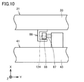
- FIG. 10 is a cross-sectional view showing a processing machine seen in the direction of arrow on the XX line in FIG. With reference to FIGS. 3 and 10, the processing machine 100 further includes a rail member 86 and a traveling wheel 88.
- the rail member 86 is provided on the first door 31.
- the rail member 86 is provided on the upper door portion 33.
- the rail member 86 has a long shape in which the Z-axis direction is the longitudinal direction.
- the rail member 86 has a groove 87.
- the groove portion 87 opens in the + Y-axis direction and has a groove shape extending in the Z-axis direction.
- the traveling wheel 88 is provided on the second door 41.
- the traveling wheel 88 is provided on the upper door portion 43.
- the traveling wheel 88 is provided at a position closer to the end of the second door 41 in the + Z axis direction than the end of the second door 41 in the ⁇ Z axis direction in the Z axis direction.
- the traveling wheel 88 is provided so as to be rotatable around a rotating shaft 124 extending in the Y-axis direction.
- the traveling wheel 88 is composed of, for example, a cam follower.
- the rail member 86 receives the weight of the second door 41 through the traveling wheel 88.
- the groove 87 is engaged with the second door 41. More specifically, the traveling wheel 88 is fitted in the groove portion 87.
- the second door 41 is supported so as to be slidable in the Z-axis direction by the traveling wheel 88 moving along the rail member 86 while rotating around the rotation shaft 124.
- the rail member 86 provided on the first door 31 receives the weight of the second door 41 through the traveling wheel 88.
- the end portion of the second door 41 in the + Z axis direction is downward. Can be prevented from tilting to.
- FIG. 11 is a cross-sectional view showing a processing machine seen in the direction of arrow on the XI-XI line in FIG.
- the processing machine 100 includes a support member 91, a ceiling rail 92, a plurality of traveling wheels 94 (94A, 94B), a ceiling rail 96, and a plurality of traveling wheels 98 (98A, 98B) and.
- the support member 91 is provided at a position adjacent to the upper door portion 33 and the upper door portion 43 in the ⁇ Y axis direction.
- the support member 91 is fixed to a frame material (not shown) arranged on the ceiling of the processing machine 100.
- the ceiling rail 92 and the ceiling rail 96 are provided on the support member 91.
- the ceiling rail 92 is provided so as to face the upper door portion 43 in the Y-axis direction.
- the ceiling rail 96 is provided so as to face the upper door portion 33 in the Y-axis direction.
- the ceiling rail 92 is provided below the ceiling rail 96.
- the ceiling rail 92 and the ceiling rail 96 have a long shape in which the Z-axis direction is the longitudinal direction.
- the ceiling rail 92 is provided between the first position J, the second position K, and the third position L in the Z-axis direction.
- the ceiling rail 96 is provided between the first position J and the second position K in the Z-axis direction.
- the ceiling rail 92 has a plurality of groove portions 93 (93A, 93B).
- the groove portion 93 has a groove shape extending in the Z-axis direction.
- the groove portion 93 is arranged outside the processing area 110.
- the groove portion 93A opens in the ⁇ X axis direction and has a groove shape extending in the Z axis direction.
- the groove portion 93B opens in the + Y-axis direction and has a groove shape extending in the Z-axis direction.
- the groove portion 93A is provided above the groove portion 93B.
- the ceiling rail 96 has a plurality of groove portions 97 (97A, 97B).
- the groove portion 97 has a groove shape extending in the Z-axis direction.
- the groove portion 97 is arranged outside the processing area 110.
- the groove portion 97A opens in the ⁇ X axis direction and has a groove shape extending in the Z axis direction.
- the groove portion 97B opens in the + Y-axis direction and has a groove shape extending in the Z-axis direction.
- the groove portion 97A is provided above the groove portion 97B.
- the traveling wheel 94 is provided on the second door 41.
- the traveling wheel 94 is provided on the upper door portion 43.
- the traveling wheel 94 is composed of, for example, a cam follower.
- the traveling wheel 94A is provided so as to be rotatable about a rotating shaft 125 extending in the X-axis direction.
- the traveling wheel 94B is provided so as to be rotatable about a rotating shaft 126 extending in the Y-axis direction.
- the traveling wheel 94A and the traveling wheel 94B are provided as a pair at two locations separated in the Z-axis direction.
- the traveling wheel 94 is fitted in the groove portion 93.
- the traveling wheel 94A is fitted in the groove portion 93A
- the traveling wheel 94B is fitted in the groove portion 93B.
- the traveling wheel 94A moves along the groove 93A while rotating around the rotating shaft 125
- the traveling wheel 94B moves along the groove 93B while rotating around the rotating shaft 126, whereby the second door 41 is moved. It is supported so that it can slide in the Z-axis direction.
- the traveling wheel 98 is provided on the first door 31.
- the traveling wheel 98 is provided on the upper door portion 33.
- the traveling wheel 98 is composed of, for example, a cam follower.
- the traveling wheel 98A is provided so as to be rotatable about a rotating shaft 127 extending in the X-axis direction.
- the traveling wheel 98B is provided so as to be rotatable about a rotating shaft 128 extending in the Y-axis direction.
- the traveling wheels 98A and the traveling wheels 98B are provided as a pair at two locations separated in the Z-axis direction.
- the traveling wheel 98 is fitted in the groove portion 97.
- the traveling wheel 98A is fitted in the groove portion 97A
- the traveling wheel 98B is fitted in the groove portion 97B.
- the traveling wheel 98A moves along the groove 97A while rotating around the rotating shaft 127
- the traveling wheel 98B moves along the groove 97B while rotating around the rotating shaft 128, whereby the first door 31 is moved. It is supported so that it can slide in the Z-axis direction.
- the processing machine 100 in the present embodiment has an opening 50, a cover body 21 for partitioning the processing area 110, a first position J for opening the opening 50, and a second position for closing the opening 50.
- a first door 31 that is slidable in the horizontal direction as a predetermined direction between K and a first position J that is arranged so as to overlap the first door 31 from the inside of the processing area 110 and opens the opening 50, and a first position.
- a second door 41 that is located on the opposite side of the first position J with respect to the second position K and can slide horizontally between the first door 31 and the third position L that closes the opening 50, and the first door.
- a rail member that includes a groove 62 and an abutting portion 63 as engaging portions that engage with the door 31, and is provided on the second door 41 so that the second door 41 can slide horizontally with respect to the first door 31. It is equipped with 61.
- the groove portion 62 and the contact portion 63 are arranged outside the machining area 110.
- the slide mechanism applied to the processing machine 100 in the present embodiment includes a first door 31 as a base member, a second door 41 as a movable body slidable in a horizontal direction as a predetermined direction, and a second door.
- the door 41 is provided with a rail member 61 that engages with the first door 31 so that the second door 41 can slide horizontally with respect to the first door 31.
- first door 31 and the second door 41 slidable in the horizontal direction have been described, but the present invention is not limited to this, and the first door and the second door in the present invention are, for example, in the vertical direction. It may be slidable.
- processing machine in the present invention is not limited to the multi-tasking machine, and may be, for example, a lathe, a vertical machining center or a horizontal machining center, and AM (Additive manufacturing) processing of a work. ) And an AM / SM hybrid processing machine capable of removing a work (SM (Subtractive manufacturing) processing).
- slide mechanism in the present invention is not limited to the door of a processing machine, and can be applied to, for example, an automobile door or an automatic door.
- the present invention is applied to a processing machine provided with a door that can be opened and closed, or a slide mechanism such as a door.
Landscapes
- Engineering & Computer Science (AREA)
- Mechanical Engineering (AREA)
- Auxiliary Devices For Machine Tools (AREA)
Priority Applications (5)
| Application Number | Priority Date | Filing Date | Title |
|---|---|---|---|
| CN202080100898.3A CN115666845B (zh) | 2020-05-14 | 2020-05-14 | 加工机械和滑动机构 |
| PCT/JP2020/019223 WO2021229738A1 (ja) | 2020-05-14 | 2020-05-14 | 加工機械およびスライド機構 |
| EP20935021.4A EP4151360A4 (en) | 2020-05-14 | 2020-05-14 | PROCESSING MACHINE AND SLIDING MECHANISM |
| JP2022522424A JP7289989B2 (ja) | 2020-05-14 | 2020-05-14 | 加工機械 |
| US17/924,733 US12415243B2 (en) | 2020-05-14 | 2020-05-14 | Processing machine and slide mechanism |
Applications Claiming Priority (1)
| Application Number | Priority Date | Filing Date | Title |
|---|---|---|---|
| PCT/JP2020/019223 WO2021229738A1 (ja) | 2020-05-14 | 2020-05-14 | 加工機械およびスライド機構 |
Publications (1)
| Publication Number | Publication Date |
|---|---|
| WO2021229738A1 true WO2021229738A1 (ja) | 2021-11-18 |
Family
ID=78525492
Family Applications (1)
| Application Number | Title | Priority Date | Filing Date |
|---|---|---|---|
| PCT/JP2020/019223 Ceased WO2021229738A1 (ja) | 2020-05-14 | 2020-05-14 | 加工機械およびスライド機構 |
Country Status (5)
| Country | Link |
|---|---|
| US (1) | US12415243B2 (https=) |
| EP (1) | EP4151360A4 (https=) |
| JP (1) | JP7289989B2 (https=) |
| CN (1) | CN115666845B (https=) |
| WO (1) | WO2021229738A1 (https=) |
Cited By (2)
| Publication number | Priority date | Publication date | Assignee | Title |
|---|---|---|---|---|
| JP2024039599A (ja) * | 2022-09-09 | 2024-03-22 | ヤマザキマザック株式会社 | 工作機械、工作機械のドア構造、及び、工作機械のフレーム構造 |
| JP7761707B1 (ja) * | 2024-06-25 | 2025-10-28 | Towa株式会社 | 切断装置及び切断品の製造方法 |
Families Citing this family (4)
| Publication number | Priority date | Publication date | Assignee | Title |
|---|---|---|---|---|
| DE202018106055U1 (de) * | 2018-10-23 | 2020-01-24 | Igus Gmbh | Teleskopabdeckung für eine Werkzeugmaschine |
| JP7306975B2 (ja) * | 2019-11-29 | 2023-07-11 | ファナック株式会社 | 支持構造 |
| US12315652B2 (en) * | 2023-03-15 | 2025-05-27 | Baker Hughes Holdings Llc | X-ray shielding cabinet |
| CN117818676A (zh) * | 2024-01-04 | 2024-04-05 | 中车唐山机车车辆有限公司 | 矿井轨道车辆 |
Citations (6)
| Publication number | Priority date | Publication date | Assignee | Title |
|---|---|---|---|---|
| DE3513944A1 (de) * | 1985-04-18 | 1986-10-23 | Chiron-Werke Gmbh, 7200 Tuttlingen | Verkleidung einer werkzeugmaschine |
| JPH1170440A (ja) * | 1997-08-27 | 1999-03-16 | Makino Milling Mach Co Ltd | 工作機械 |
| JPH11247536A (ja) * | 1998-02-27 | 1999-09-14 | Hou-Tech Co Ltd | 引き扉装置 |
| US20050095074A1 (en) * | 2003-11-01 | 2005-05-05 | Michael Hacker | Machine tool installation including gated enclosure |
| JP2010228045A (ja) * | 2009-03-27 | 2010-10-14 | Brother Ind Ltd | 工作機械 |
| JP2013193197A (ja) | 2012-03-23 | 2013-09-30 | Okamoto Machine Tool Works Ltd | 工作機械用開閉扉の摺動案内装置 |
Family Cites Families (14)
| Publication number | Priority date | Publication date | Assignee | Title |
|---|---|---|---|---|
| DE8620297U1 (de) * | 1986-07-29 | 1988-07-07 | HCR-Heinrich Cremer GmbH, 41199 Mönchengladbach | Öffnungseinrichtung für sich überlappende, an parallelen Führungsbahnen von Werkzeugmaschinenkabinen geführte Schiebetore |
| DE29517783U1 (de) * | 1995-11-10 | 1996-01-11 | Hawema Werkzeugschleifmaschinen GmbH, 78647 Trossingen | Schutzkabine |
| JP3875967B2 (ja) * | 2003-08-12 | 2007-01-31 | ナブテスコ株式会社 | プラグドア装置 |
| JP4534774B2 (ja) * | 2005-01-31 | 2010-09-01 | ブラザー工業株式会社 | ドア装置および当該ドア装置を備えた工作機械 |
| JP4773246B2 (ja) * | 2006-03-31 | 2011-09-14 | オークマ株式会社 | 並列2主軸旋盤のカバー構造 |
| JP5154807B2 (ja) * | 2007-02-16 | 2013-02-27 | スガツネ工業株式会社 | 二重扉装置 |
| JP4787895B2 (ja) * | 2009-08-25 | 2011-10-05 | タキゲン製造株式会社 | 扉用埋込み取手 |
| JP5786659B2 (ja) * | 2011-11-07 | 2015-09-30 | 豊和工業株式会社 | スライド装置、及び工作機械におけるカバー装置 |
| JP6104770B2 (ja) * | 2013-09-13 | 2017-03-29 | オークマ株式会社 | 工作機械におけるドアのスライド機構 |
| TWM471326U (zh) * | 2013-09-18 | 2014-02-01 | Dao-Xi Huang | 具穩定性之拉門 |
| JP5937713B1 (ja) * | 2015-03-20 | 2016-06-22 | Dmg森精機株式会社 | 加工機械 |
| KR20170116740A (ko) * | 2016-04-12 | 2017-10-20 | 두산공작기계 주식회사 | 공작 기계의 도어 개폐 장치 |
| JP6322242B2 (ja) * | 2016-09-02 | 2018-05-09 | 株式会社オーエム製作所 | 工作機械 |
| CN110587325B (zh) * | 2019-10-23 | 2021-07-20 | 长春光华学院 | 一种调节式数控机床导轨防护罩 |
-
2020
- 2020-05-14 WO PCT/JP2020/019223 patent/WO2021229738A1/ja not_active Ceased
- 2020-05-14 JP JP2022522424A patent/JP7289989B2/ja active Active
- 2020-05-14 CN CN202080100898.3A patent/CN115666845B/zh active Active
- 2020-05-14 US US17/924,733 patent/US12415243B2/en active Active
- 2020-05-14 EP EP20935021.4A patent/EP4151360A4/en active Pending
Patent Citations (6)
| Publication number | Priority date | Publication date | Assignee | Title |
|---|---|---|---|---|
| DE3513944A1 (de) * | 1985-04-18 | 1986-10-23 | Chiron-Werke Gmbh, 7200 Tuttlingen | Verkleidung einer werkzeugmaschine |
| JPH1170440A (ja) * | 1997-08-27 | 1999-03-16 | Makino Milling Mach Co Ltd | 工作機械 |
| JPH11247536A (ja) * | 1998-02-27 | 1999-09-14 | Hou-Tech Co Ltd | 引き扉装置 |
| US20050095074A1 (en) * | 2003-11-01 | 2005-05-05 | Michael Hacker | Machine tool installation including gated enclosure |
| JP2010228045A (ja) * | 2009-03-27 | 2010-10-14 | Brother Ind Ltd | 工作機械 |
| JP2013193197A (ja) | 2012-03-23 | 2013-09-30 | Okamoto Machine Tool Works Ltd | 工作機械用開閉扉の摺動案内装置 |
Non-Patent Citations (1)
| Title |
|---|
| See also references of EP4151360A4 |
Cited By (4)
| Publication number | Priority date | Publication date | Assignee | Title |
|---|---|---|---|---|
| JP2024039599A (ja) * | 2022-09-09 | 2024-03-22 | ヤマザキマザック株式会社 | 工作機械、工作機械のドア構造、及び、工作機械のフレーム構造 |
| JP7588681B2 (ja) | 2022-09-09 | 2024-11-22 | ヤマザキマザック株式会社 | 工作機械、工作機械のドア構造、及び、工作機械のフレーム構造 |
| JP7761707B1 (ja) * | 2024-06-25 | 2025-10-28 | Towa株式会社 | 切断装置及び切断品の製造方法 |
| WO2026004454A1 (ja) * | 2024-06-25 | 2026-01-02 | Towa株式会社 | 切断装置及び切断品の製造方法 |
Also Published As
| Publication number | Publication date |
|---|---|
| JP7289989B2 (ja) | 2023-06-12 |
| US12415243B2 (en) | 2025-09-16 |
| EP4151360A1 (en) | 2023-03-22 |
| CN115666845B (zh) | 2025-10-21 |
| EP4151360A4 (en) | 2023-07-05 |
| CN115666845A (zh) | 2023-01-31 |
| JPWO2021229738A1 (https=) | 2021-11-18 |
| US20230182252A1 (en) | 2023-06-15 |
Similar Documents
| Publication | Publication Date | Title |
|---|---|---|
| WO2021229738A1 (ja) | 加工機械およびスライド機構 | |
| US4999895A (en) | Machine tool | |
| CN105473278B (zh) | 机床 | |
| JP6199511B1 (ja) | 複合加工装置及び複合加工方法 | |
| WO2014024319A1 (ja) | 立型マシニングセンタ | |
| EP1525946A1 (en) | Horizontal machining center | |
| JP2019025555A (ja) | ワーク搬送装置 | |
| JP2018027612A (ja) | 複合加工装置 | |
| JP2023083237A (ja) | レーザ加工機のハウジング及びハウジングを有するレーザ加工機 | |
| KR20230084073A (ko) | 레이저 가공 기계를 위한 하우징 및 하우징을 갖는 레이저 가공 기계 | |
| US7229395B2 (en) | Cover structure of a machine tool | |
| CN112789139B (zh) | 加工系统 | |
| JP7299417B2 (ja) | 工作機械 | |
| WO2022249404A1 (ja) | 自動パレット交換装置 | |
| JP2021504167A (ja) | 工作機械 | |
| WO2022201850A1 (ja) | 工作機械 | |
| JPH09150343A (ja) | 防塵カバー | |
| JPH0811035A (ja) | 工作機械のドア装置 | |
| JP7742465B1 (ja) | 工作機械 | |
| JP2001341048A (ja) | 主軸移動型工作機械におけるスプラッシュガード | |
| JP7588681B2 (ja) | 工作機械、工作機械のドア構造、及び、工作機械のフレーム構造 | |
| CN105531078A (zh) | 机床 | |
| WO2022259455A1 (ja) | 複合加工機 | |
| JPH0518030Y2 (https=) | ||
| WO2024116345A1 (ja) | 扉駆動装置及び該扉駆動装置を備えた工作機械 |
Legal Events
| Date | Code | Title | Description |
|---|---|---|---|
| 121 | Ep: the epo has been informed by wipo that ep was designated in this application |
Ref document number: 20935021 Country of ref document: EP Kind code of ref document: A1 |
|
| ENP | Entry into the national phase |
Ref document number: 2022522424 Country of ref document: JP Kind code of ref document: A |
|
| NENP | Non-entry into the national phase |
Ref country code: DE |
|
| ENP | Entry into the national phase |
Ref document number: 2020935021 Country of ref document: EP Effective date: 20221214 |
|
| WWG | Wipo information: grant in national office |
Ref document number: 17924733 Country of ref document: US |
|
| WWG | Wipo information: grant in national office |
Ref document number: 202080100898.3 Country of ref document: CN |