WO2021220550A1 - スリット耳部のズレ防止機構を有する光学フィルムストリップロールを製造する装置および方法 - Google Patents
スリット耳部のズレ防止機構を有する光学フィルムストリップロールを製造する装置および方法 Download PDFInfo
- Publication number
- WO2021220550A1 WO2021220550A1 PCT/JP2020/048021 JP2020048021W WO2021220550A1 WO 2021220550 A1 WO2021220550 A1 WO 2021220550A1 JP 2020048021 W JP2020048021 W JP 2020048021W WO 2021220550 A1 WO2021220550 A1 WO 2021220550A1
- Authority
- WO
- WIPO (PCT)
- Prior art keywords
- selvage
- winding
- continuous
- roll
- optical film
- Prior art date
- Legal status (The legal status is an assumption and is not a legal conclusion. Google has not performed a legal analysis and makes no representation as to the accuracy of the status listed.)
- Ceased
Links
Images

Classifications
-
- B—PERFORMING OPERATIONS; TRANSPORTING
- B32—LAYERED PRODUCTS
- B32B—LAYERED PRODUCTS, i.e. PRODUCTS BUILT-UP OF STRATA OF FLAT OR NON-FLAT, e.g. CELLULAR OR HONEYCOMB, FORM
- B32B3/00—Layered products comprising a layer with external or internal discontinuities or unevennesses, or a layer of non-planar shape; Layered products comprising a layer having particular features of form
- B32B3/10—Layered products comprising a layer with external or internal discontinuities or unevennesses, or a layer of non-planar shape; Layered products comprising a layer having particular features of form characterised by a discontinuous layer, i.e. formed of separate pieces of material
- B32B3/12—Layered products comprising a layer with external or internal discontinuities or unevennesses, or a layer of non-planar shape; Layered products comprising a layer having particular features of form characterised by a discontinuous layer, i.e. formed of separate pieces of material characterised by a layer of regularly- arranged cells, e.g. a honeycomb structure
-
- B—PERFORMING OPERATIONS; TRANSPORTING
- B65—CONVEYING; PACKING; STORING; HANDLING THIN OR FILAMENTARY MATERIAL
- B65H—HANDLING THIN OR FILAMENTARY MATERIAL, e.g. SHEETS, WEBS, CABLES
- B65H18/00—Winding webs
- B65H18/02—Supporting web roll
- B65H18/06—Lateral-supporting
-
- B—PERFORMING OPERATIONS; TRANSPORTING
- B65—CONVEYING; PACKING; STORING; HANDLING THIN OR FILAMENTARY MATERIAL
- B65H—HANDLING THIN OR FILAMENTARY MATERIAL, e.g. SHEETS, WEBS, CABLES
- B65H35/00—Delivering articles from cutting or line-perforating machines; Article or web delivery apparatus incorporating cutting or line-perforating devices, e.g. adhesive tape dispensers
- B65H35/02—Delivering articles from cutting or line-perforating machines; Article or web delivery apparatus incorporating cutting or line-perforating devices, e.g. adhesive tape dispensers from or with longitudinal slitters or perforators
-
- G—PHYSICS
- G02—OPTICS
- G02B—OPTICAL ELEMENTS, SYSTEMS OR APPARATUS
- G02B5/00—Optical elements other than lenses
- G02B5/30—Polarising elements
-
- G—PHYSICS
- G02—OPTICS
- G02F—OPTICAL DEVICES OR ARRANGEMENTS FOR THE CONTROL OF LIGHT BY MODIFICATION OF THE OPTICAL PROPERTIES OF THE MEDIA OF THE ELEMENTS INVOLVED THEREIN; NON-LINEAR OPTICS; FREQUENCY-CHANGING OF LIGHT; OPTICAL LOGIC ELEMENTS; OPTICAL ANALOGUE/DIGITAL CONVERTERS
- G02F1/00—Devices or arrangements for the control of the intensity, colour, phase, polarisation or direction of light arriving from an independent light source, e.g. switching, gating or modulating; Non-linear optics
- G02F1/01—Devices or arrangements for the control of the intensity, colour, phase, polarisation or direction of light arriving from an independent light source, e.g. switching, gating or modulating; Non-linear optics for the control of the intensity, phase, polarisation or colour
- G02F1/13—Devices or arrangements for the control of the intensity, colour, phase, polarisation or direction of light arriving from an independent light source, e.g. switching, gating or modulating; Non-linear optics for the control of the intensity, phase, polarisation or colour based on liquid crystals, e.g. single liquid crystal display cells
- G02F1/133—Constructional arrangements; Operation of liquid crystal cells; Circuit arrangements
- G02F1/1333—Constructional arrangements; Manufacturing methods
- G02F1/1335—Structural association of cells with optical devices, e.g. polarisers or reflectors
-
- G—PHYSICS
- G09—EDUCATION; CRYPTOGRAPHY; DISPLAY; ADVERTISING; SEALS
- G09F—DISPLAYING; ADVERTISING; SIGNS; LABELS OR NAME-PLATES; SEALS
- G09F9/00—Indicating arrangements for variable information in which the information is built-up on a support by selection or combination of individual elements
-
- B—PERFORMING OPERATIONS; TRANSPORTING
- B65—CONVEYING; PACKING; STORING; HANDLING THIN OR FILAMENTARY MATERIAL
- B65H—HANDLING THIN OR FILAMENTARY MATERIAL, e.g. SHEETS, WEBS, CABLES
- B65H2301/00—Handling processes for sheets or webs
- B65H2301/40—Type of handling process
- B65H2301/41—Winding, unwinding
- B65H2301/413—Supporting web roll
- B65H2301/4136—Mounting arrangements not otherwise provided for
- B65H2301/41368—Mounting arrangements not otherwise provided for one or two lateral flanges covering part of or entire web diameter
-
- B—PERFORMING OPERATIONS; TRANSPORTING
- B65—CONVEYING; PACKING; STORING; HANDLING THIN OR FILAMENTARY MATERIAL
- B65H—HANDLING THIN OR FILAMENTARY MATERIAL, e.g. SHEETS, WEBS, CABLES
- B65H2301/00—Handling processes for sheets or webs
- B65H2301/50—Auxiliary process performed during handling process
- B65H2301/51—Modifying a characteristic of handled material
- B65H2301/515—Cutting handled material
- B65H2301/5155—Cutting handled material longitudinally
-
- B—PERFORMING OPERATIONS; TRANSPORTING
- B65—CONVEYING; PACKING; STORING; HANDLING THIN OR FILAMENTARY MATERIAL
- B65H—HANDLING THIN OR FILAMENTARY MATERIAL, e.g. SHEETS, WEBS, CABLES
- B65H2701/00—Handled material; Storage means
- B65H2701/10—Handled articles or webs
- B65H2701/17—Nature of material
- B65H2701/175—Plastic
- B65H2701/1752—Polymer film
-
- B—PERFORMING OPERATIONS; TRANSPORTING
- B65—CONVEYING; PACKING; STORING; HANDLING THIN OR FILAMENTARY MATERIAL
- B65H—HANDLING THIN OR FILAMENTARY MATERIAL, e.g. SHEETS, WEBS, CABLES
- B65H2701/00—Handled material; Storage means
- B65H2701/10—Handled articles or webs
- B65H2701/19—Specific article or web
Definitions
- the present invention relates to an apparatus and a method for manufacturing an optical film strip roll having a long side or a short side width of an optical display device.
- both ends of the optical film strip unwound from the original roll mounted on the feeding device in the width direction are slit in the feeding direction by at least one set of rotary blades, and continuous ears are provided.
- the optical film strip formed to a predetermined width is wound around the rotation axis of the winding device to manufacture a roll of the optical film strip having a predetermined width, and on the other hand, a set of continuous ears cut off is used. It is wound around each rotation axis of the selvage winding device to form a continuous roll of the selvage portion, and is continuously formed on each rotation axis of the set of selvage winding devices when the roll of the selvage portion is further formed.
- An optical display device manufactured by the RTP method is typically a long side or a short side of a rectangular liquid crystal display panel, as shown in FIGS. 5 to 7 of Japanese Patent No. 5616494 (Patent Document 1). Manufactured by using a pair of polarizing film strips of predetermined width corresponding to the sides and continuously bonding two polarizing film strips of different predetermined widths on both sides of the liquid crystal display panel so that the transmission axes are orthogonal to each other. NS.
- optical display devices manufactured by the RTP method have become more polarized in size and size, while larger optical display devices require design, and on the other hand, smaller optical displays.
- the demand for narrowing the frame is increasing due to the demand for expansion of the display area.
- the display area extends to the end of the optical film strip formed to a predetermined width, the demand for cutting accuracy of the predetermined width in the production of the roll naturally increases.
- the required accuracy is too high, and it is not always easy to realize it.
- Patent Document 2 describes "a method for producing a laminated strip roll having a polarizing film", in which the slitter device is a paragraph using FIG. 32, which is a schematic diagram.
- “Three sheets” to the feed of the laminate in connection with the manufacture of an optical display device configured to be attached to a rectangular liquid crystal display panel having a long side and a short side” from 0215 to 0216.
- the disk-shaped rotary cutting blades are arranged at intervals in the width direction. ”
- the rotary cutting blades placed on both ends of the laminate are drawn out by slitting and cutting off both end faces in the width direction of the laminate.
- the rotary cutting blades arranged in the above are configured to cut optical film laminate strips having a width corresponding to the long side and the short side of the liquid crystal panel, respectively, and the production of two rolls having different predetermined widths is described. ..
- Patent Document 2 does not describe a method for treating continuous ears cut off from both end faces in the width direction of the laminate.
- Patent Document 3 Patent No. 5877257
- Devices and methods for forming an optical film laminate strip are described in the same manner as in Patent Document 2, and among them, more accurate
- the operation of the slitter device having three sets of circular cutting blades composed of a pair of upper and lower parts capable of high cutting is described in paragraphs 0067 to 0068 using schematic views 1 to 3 as follows. ..
- strips of two "optical film laminates" having different predetermined widths are formed from the “optical film laminate” unwound by three sets of circular cutting blades, and are wound around each rotation axis of the corresponding winding device.
- Two rolls of different predetermined widths are manufactured, and continuous ears cut off from both ends of the strip by two sets of circular cutting blades arranged on both ends of the "optical film laminate” strip. It is stated that “it is wound on another winding shaft (not shown) and discarded”.
- Patent Documents 2 and 3 describe that both ends of the drawn optical film strip in the width direction are slit and continuous ears are cut off to form an optical film strip having a predetermined width, the manufactured optics are manufactured. Regardless of the size of the target display device, it was not sufficient to meet the strict cutting accuracy required in the production of rolls of optical film strips, which has been required in recent years.
- the required accuracy of narrowing the frame of the optical display device is extremely high. Specifically, the slit width in the set value of the roll having a predetermined width manufactured from the original roll used in the RTP method exceeds ⁇ 0.3 mm, or the edge floats, fluff, burrs, etc. caused by the slit. It is symbolized that when the width of the end face abnormality exceeds 0.3 mm, the required accuracy becomes x (it becomes a rejected product).
- the maximum amount of deviation of the slit width in the set value of the roll having a predetermined width and the maximum width of the end face abnormality such as floating, fluffing, and burrs of the end portion caused by the slit are referred to as slit accuracy.
- the continuous ear part that has been cut off in the past is discarded afterwards, its handling is not sufficiently controlled, and the ear part is wound up and collected as it is by the ear part winding device, or the wound ear part is wound up.
- the winding was wound while swinging with respect to the rotating shaft so that the winding diameter would not increase in a short time. Succeeded in achieving a slit accuracy that does not exceed ⁇ 0.3 mm by controlling the winding and collection of the discarded ear.
- the present invention provides an apparatus for producing a roll of an optical film strip having a long side or a short side width of an optical display device. More specifically, the present device uses at least one set of rotary blades to slit both ends of the optical film strip unwound from the original roll of the feeding device in the feeding direction and cut off continuous ears.
- a width-formed optical film strip is wound by a winder to produce a roll of a predetermined width, while a continuous selvage cut off is wound around each axis of rotation of a set of selvage winders. It relates to a device for forming a roll of the ear.
- the device further winds continuously on each axis of rotation of a set of selvage winders so that the selvage winding does not deviate in the width direction when forming the selvage roll.
- the present invention relates to a device that rotates by integrally equipping each rotating shaft with jigs that support the ears from both sides in the width direction.
- This device also has a feeding device for feeding the optical film strip from the original roll, and slits at both ends in the width direction with respect to the feeding direction of the optical film strip, which is arranged on the downstream side of the feeding device, and cuts off continuous ears.
- a winding device for producing a winding roll of a predetermined width optical film strip which comprises at least one set of rotary blades and is arranged downstream of the set of rotary blades, which is formed into a predetermined width optical film strip.
- a set of selvage winder with a rotating shaft that winds up the continuous selvage and forms the selvage roll 31. Includes equipment.
- a set of selvage winding devices of this device when the continuous ears are wound around the rotation axis, the continuous ears are stably wound so as not to collapse or shift in the width direction.
- a jig that supports the winding of the selvage portion continuous with each rotation axis of the set of ear winding devices from both side surfaces in the width direction and rotates integrally with each rotation axis is equipped.
- the jig is supported by a flat plate from one end surface side of a continuous selvage portion to be wound and fixed to each rotating shaft of a set of selvage winding devices. It may consist of one jig and a second jig that is freely attached to the rotating shaft with the width of the continuous selvage and is supported by a flat plate from the other end surface side of the continuous selvage to be wound up. preferable.
- the present invention provides, in the second aspect, a method of manufacturing an optical film strip roll having a long side or a short side width of an optical display device. More specifically, the present method uses a feeding step of feeding the optical film strip from the original roll and at least one set of rotary blades arranged on the downstream side in the feeding step to hold both ends of the optical film strip in the width direction.
- a predetermined width of the optical film strip is wound up by a slit process of slitting, cutting off the continuous ears, and forming into an optical film strip having a predetermined width, and a winding device arranged on the downstream side of the rotary blade, and having a predetermined width.
- a selvage winding device having a winding process for manufacturing the roll and a selvage winding device arranged on the downstream side of the rotary blade winds the selvage portion continuously to form a roll of the selvage portion.
- the selvage winding device includes a selvage roll forming step, and the selvage winding device has a jig that rotates integrally with the selvage while supporting the continuous winding of the selvage of the selvage shaft from both side surfaces in the width direction.
- the selvage roll forming step when the selvage portion is wound around the rotation shaft by the jig of the selvage winding device, the roll of the selvage portion does not shift in the width direction. It relates to a method characterized in that it is wound up like this.
- the jig of the selvage winding device is fitted and fixed to the selvage shaft to wind the selvage portion continuously from one end surface side of the selvage portion to a flat plate.
- the first jig supported by the above and the continuous winding of the selvage portion, which is fixed to the rotating shaft with the width of the continuous selvage portion, is supported by a flat plate from the other end surface side of the selvage portion. It is preferably composed of two jigs.
- a second jig that supports the continuous ear part to be wound with a flat plate from the other end surface side with respect to the one end surface jig fitted and fixed to the rotation shaft of the selvage winding device can be freely attached with the width of the continuous ear part. It is a schematic diagram which shows the state fixed to. It is a schematic diagram which shows the state which the 2nd jig which was fixed to the rotary shaft of the selvage winding device is detached from the rotary shaft.
- a set of devices and methods of selvage winding When the selvage is wound around the axis of rotation, the continuous selvage is stably wound, causing collapse and displacement in the width direction.
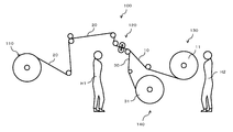
- FIG. 1 is a schematic side view showing the present apparatus 100 for manufacturing the roll 11 of the optical film strip 10 having a predetermined width.
- the manufacturing process is a perspective view of FIG.
- an optical film strip 10 having a long side or a short side width of a rectangular liquid crystal display panel is cut in the short side or the long side width with respect to the feeding direction, and both sides of the liquid crystal display panel are cut.
- a roll 11 corresponding to one of a set of rolls to be continuously bonded is manufactured.
- the worker H1 is responsible for the maintenance of the rotary blade 120 to be slit and the replacement work of the rolled selvage roll 31, and the worker H2 is responsible for the replacement work of the roll 11 having a predetermined width of the winding device 130.
- the width of the roll 11 does not have to be exactly the same as the width of the roll 11 and the width of the long side or the short side of the liquid crystal display panel, and the optical film for the panel.
- the width of the roll 11 covers a range slightly larger than or slightly smaller than the width of the long side or the short side of the liquid crystal display panel, depending on the sticking position of the roll 11. That is, the width of the roll 11 is a width corresponding to the long side or the short side of the liquid crystal display panel.
- the cut interval with respect to the feed direction is also an interval corresponding to the short side or the long side of the liquid crystal display panel.
- a set of rotary blades 120 slits in the feed direction, cuts off the continuous ear portion 30, and the optical film strip 10 formed to a predetermined width is wound around the rotating shaft 131 of the winding device 130 to determine the predetermined width.
- a roll 11 of a width optical film strip is manufactured.
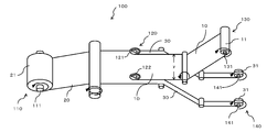
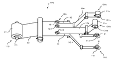
- the apparatus 100 may have three sets of rotary blades (121 to 123) arranged at intervals.
- the rotary blades 121 and 122 corresponding to both end faces in the width direction of the optical film strip 20 unwound from the original roll 21 of the feeding device 110 are slit to cut off the continuous ear portion 30 and cut off the continuous ear portion 30 in the middle.
- the arranged rotary blade 123 is configured to cut, for example, optical film strips 10a and 10b having a predetermined width corresponding to the long side and the short side of the liquid crystal panel, respectively.
- the winding device corresponding to the winding device 130 of FIG.
- 1 or 2 is a rotating shaft of each of the winding devices 130a and 130b in which the formed long side and short side optical film strips 10a and 10b are a set. It is wound around 131a and 131b to form a set of winding devices for producing a set of rolls 11a and 11b.
- a general slitter device is an optical film formed into a predetermined width by slitting both ends of the optical film strip 20 unwound from the feeding device 110 in the width direction by at least one set of rotary blades 120.
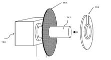
- the split 10 is wound and one roll 11 is manufactured by the winding device 130, while the cut-off continuous selvage portion is directly wound around the rotation axis of the selvage winding device 140 as shown in FIG. It is either taken or processed to drop by its own weight into a waste container (not shown).
- the continuous ears 30 cut off from the optical film strip 20 as shown in FIG. 4 are formed from both side surfaces in the width direction. It is wound around the rotating shaft 141 as it is without being supported. In addition, there is no control to wind up the discarded ears without slippage. Therefore, the continuous ear portion 30, which is cut off from the optical film strip 20 and wound around the rotating shaft 141, has a slight blur in its transportation, and the roll of a predetermined width produced due to the blur is ⁇ . It is difficult to achieve a slit accuracy that does not exceed 0.3 mm.
- the continuous ear portion 30 cut off from the optical film strip 20 is narrow, for example, a portion in which the polarizer is sandwiched by the protective film and a protective film not sandwiching the polarizing element on the outside thereof. Since there is usually a difference in thickness from the only part, it is wound as it is, and if the thickness is increased to some extent, it may collapse due to a slight winding deviation due to the above-mentioned blurring. Then what about Comparative Example 3? Dropping the cut-off continuous ear portion 30 into a waste container or the like by its own weight makes it difficult to ensure that the drop direction is not stable and the slit accuracy does not exceed ⁇ 0.3 mm.
- Comparative Example 1 of the method of winding the selvage winding device 140 while swinging the narrow and continuous selvage portion 30 cut off by the rotating shaft 141 seems to be a rational processing method.
- the winding direction of the continuous selvage portion 30 is stabilized in one direction, and is shown in the examples of Table 1. This cannot be achieved unless the continuous ears 30 are kept in a state where the winding deviation is not prevented.
- the slit accuracy of ⁇ indicates that the slit width with respect to the set value is within ⁇ 0.3 mm and the width of the end face abnormality is within 0.3 mm, and the slit accuracy is ⁇ .
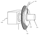
- FIGS. 5 to 7 are an embodiment showing a means for solving such a technical problem.
- FIG. 5 shows the selvage winding rotation axis of the selvage winding device 140 in the prepared state before the start of winding of the continuous selvage portion 30. More specifically, the first jig 151 that supports the continuous ear portion 30 wound around the rotary shaft 141 of the selvage winding device 140 with a flat plate from the inside on one end surface side is fitted to the rotary shaft 141. The second jig 152, which is in a fixed state but is supported by a flat plate from the outside on the other end surface side, represents a state before being mounted on the rotating shaft 141.
- the continuous ear portion 30 wound by the first jig 151 of the flat plate fitted and fixed to the rotating shaft 141 of the winding device 140 is supported from the inside, and the selvage portion 30 continuous to the rotating shaft 141 is supported. It represents a step of forming a roll 31 of a selvage portion in a state where a continuous selvage portion 30 to be wound is supported from the outside by a flat plate second jig 152 fixed so as to be able to be attached by a width.
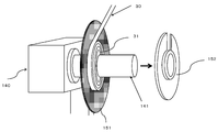
- the second jig 152 which is removably fixed from the rotary shaft 141 of the selvage winding device 140, is removed, and the continuous winding state of the selvage portion 30 is confirmed, or the selvage roll 31 is formed. It indicates a state in which the ear roll 31 can be removed after confirmation.
- both ends of the optical film strip 20 fed from the feeding device 110 in the width direction are slit by at least one set of rotary blades in the feeding direction.
- An optical film split 10 having a predetermined width is formed and wound to produce one roll 11.
- the continuous ears 30 are slit by a set of rotary blades so as not to cause the selvage rolls 31 of the continuous ears 30 to be displaced in the width direction.
- a continuous ear portion 30 that is accurately and stably cut off and is cut off by a first jig on one end surface side and a second jig on the other end surface side mounted on the rotary shaft 141 of the selvage winding device 140. Is supported from both side surfaces in the width direction, and the selvage roll 31 is formed by winding the selvage roll 31 accurately and stably around the rotating shaft 141 so as to match the slit method.
Landscapes
- Physics & Mathematics (AREA)
- General Physics & Mathematics (AREA)
- Optics & Photonics (AREA)
- Nonlinear Science (AREA)
- Chemical & Material Sciences (AREA)
- Mathematical Physics (AREA)
- Theoretical Computer Science (AREA)
- Crystallography & Structural Chemistry (AREA)
- Engineering & Computer Science (AREA)
- Polarising Elements (AREA)
- Liquid Crystal (AREA)
- Devices For Indicating Variable Information By Combining Individual Elements (AREA)
- Winding Of Webs (AREA)
Priority Applications (2)
| Application Number | Priority Date | Filing Date | Title |
|---|---|---|---|
| CN202080099952.7A CN115443423A (zh) | 2020-04-28 | 2020-12-22 | 具有分切耳部的偏移防止机构的制造光学膜带卷筒的装置以及方法 |
| KR1020227034965A KR20230002370A (ko) | 2020-04-28 | 2020-12-22 | 슬릿 에지부의 어긋남 방지 기구를 갖는 광학 필름 스트립 롤을 제조하는 장치 및 방법 |
Applications Claiming Priority (2)
| Application Number | Priority Date | Filing Date | Title |
|---|---|---|---|
| JP2020079057A JP7349405B2 (ja) | 2020-04-28 | 2020-04-28 | スリット耳部のズレ防止機構を有する光学フィルムストリップロールを製造する装置および方法 |
| JP2020-079057 | 2020-04-28 |
Publications (1)
| Publication Number | Publication Date |
|---|---|
| WO2021220550A1 true WO2021220550A1 (ja) | 2021-11-04 |
Family
ID=78281705
Family Applications (1)
| Application Number | Title | Priority Date | Filing Date |
|---|---|---|---|
| PCT/JP2020/048021 Ceased WO2021220550A1 (ja) | 2020-04-28 | 2020-12-22 | スリット耳部のズレ防止機構を有する光学フィルムストリップロールを製造する装置および方法 |
Country Status (5)
| Country | Link |
|---|---|
| JP (1) | JP7349405B2 (enExample) |
| KR (1) | KR20230002370A (enExample) |
| CN (1) | CN115443423A (enExample) |
| TW (1) | TWI859392B (enExample) |
| WO (1) | WO2021220550A1 (enExample) |
Citations (14)
| Publication number | Priority date | Publication date | Assignee | Title |
|---|---|---|---|---|
| US4719832A (en) * | 1986-06-09 | 1988-01-19 | Blazej Svihra | Copper foil cutter |
| JPH01203144A (ja) * | 1988-02-04 | 1989-08-15 | Takeda Chem Ind Ltd | シート状成形材料の巻取装置 |
| JPH04280767A (ja) * | 1991-03-08 | 1992-10-06 | Toray Ind Inc | シート状物用スリッタの耳部巻取張力制御装置 |
| JPH04372396A (ja) * | 1991-06-17 | 1992-12-25 | Fuji Photo Film Co Ltd | 裁断方法とそれによって得られたカ−ボンブラック入ポリオレフィン樹脂積層フイルム |
| JPH05229702A (ja) * | 1992-02-19 | 1993-09-07 | Tokyo Electric Co Ltd | 用紙巻取装置 |
| JPH07257796A (ja) * | 1994-03-23 | 1995-10-09 | Fuji Tekkosho:Kk | スリッタにおける耳屑巻取装置 |
| JPH11322143A (ja) * | 1998-05-11 | 1999-11-24 | Fujimori Kogyo Kk | シート巻取り装置およびシート巻取り方法 |
| JP2001048382A (ja) * | 1999-08-12 | 2001-02-20 | Fuji Photo Film Co Ltd | ウェブ裁断装置およびその制御方法 |
| JP2003321151A (ja) * | 2002-05-02 | 2003-11-11 | Millennium Service Corporation:Kk | 巻物支持軸、巻取装置および巻出装置 |
| JP2009214513A (ja) * | 2008-03-13 | 2009-09-24 | Mitsubishi Plastics Inc | 離型性フィルムテープ・ロール及びその製造方法 |
| JP2009292006A (ja) * | 2008-06-04 | 2009-12-17 | Konica Minolta Opto Inc | 光学フィルム及び光学フィルムの製造方法 |
| JP2010247973A (ja) * | 2009-04-17 | 2010-11-04 | Kunimi-Kougyo Corp | 帯状シート材の巻取装置 |
| JP5877257B2 (ja) * | 2014-04-11 | 2016-03-02 | 日東電工株式会社 | 光学フィルム積層体ストリップを形成する装置及び方法 |
| JP2019094194A (ja) * | 2017-11-27 | 2019-06-20 | 信越ポリマー株式会社 | キャリアテープの巻回方法 |
Family Cites Families (2)
| Publication number | Priority date | Publication date | Assignee | Title |
|---|---|---|---|---|
| JPS5616494B2 (enExample) | 1973-02-05 | 1981-04-16 | ||
| JP5361941B2 (ja) | 2010-09-03 | 2013-12-04 | 日東電工株式会社 | 偏光膜を有する積層体ストリップロールの製造方法 |
-
2020
- 2020-04-28 JP JP2020079057A patent/JP7349405B2/ja active Active
- 2020-12-22 WO PCT/JP2020/048021 patent/WO2021220550A1/ja not_active Ceased
- 2020-12-22 CN CN202080099952.7A patent/CN115443423A/zh active Pending
- 2020-12-22 KR KR1020227034965A patent/KR20230002370A/ko active Pending
- 2020-12-31 TW TW109147008A patent/TWI859392B/zh active
Patent Citations (14)
| Publication number | Priority date | Publication date | Assignee | Title |
|---|---|---|---|---|
| US4719832A (en) * | 1986-06-09 | 1988-01-19 | Blazej Svihra | Copper foil cutter |
| JPH01203144A (ja) * | 1988-02-04 | 1989-08-15 | Takeda Chem Ind Ltd | シート状成形材料の巻取装置 |
| JPH04280767A (ja) * | 1991-03-08 | 1992-10-06 | Toray Ind Inc | シート状物用スリッタの耳部巻取張力制御装置 |
| JPH04372396A (ja) * | 1991-06-17 | 1992-12-25 | Fuji Photo Film Co Ltd | 裁断方法とそれによって得られたカ−ボンブラック入ポリオレフィン樹脂積層フイルム |
| JPH05229702A (ja) * | 1992-02-19 | 1993-09-07 | Tokyo Electric Co Ltd | 用紙巻取装置 |
| JPH07257796A (ja) * | 1994-03-23 | 1995-10-09 | Fuji Tekkosho:Kk | スリッタにおける耳屑巻取装置 |
| JPH11322143A (ja) * | 1998-05-11 | 1999-11-24 | Fujimori Kogyo Kk | シート巻取り装置およびシート巻取り方法 |
| JP2001048382A (ja) * | 1999-08-12 | 2001-02-20 | Fuji Photo Film Co Ltd | ウェブ裁断装置およびその制御方法 |
| JP2003321151A (ja) * | 2002-05-02 | 2003-11-11 | Millennium Service Corporation:Kk | 巻物支持軸、巻取装置および巻出装置 |
| JP2009214513A (ja) * | 2008-03-13 | 2009-09-24 | Mitsubishi Plastics Inc | 離型性フィルムテープ・ロール及びその製造方法 |
| JP2009292006A (ja) * | 2008-06-04 | 2009-12-17 | Konica Minolta Opto Inc | 光学フィルム及び光学フィルムの製造方法 |
| JP2010247973A (ja) * | 2009-04-17 | 2010-11-04 | Kunimi-Kougyo Corp | 帯状シート材の巻取装置 |
| JP5877257B2 (ja) * | 2014-04-11 | 2016-03-02 | 日東電工株式会社 | 光学フィルム積層体ストリップを形成する装置及び方法 |
| JP2019094194A (ja) * | 2017-11-27 | 2019-06-20 | 信越ポリマー株式会社 | キャリアテープの巻回方法 |
Also Published As
| Publication number | Publication date |
|---|---|
| JP7349405B2 (ja) | 2023-09-22 |
| TW202141084A (zh) | 2021-11-01 |
| TWI859392B (zh) | 2024-10-21 |
| KR20230002370A (ko) | 2023-01-05 |
| JP2021173916A (ja) | 2021-11-01 |
| CN115443423A (zh) | 2022-12-06 |
Similar Documents
| Publication | Publication Date | Title |
|---|---|---|
| US20140085723A1 (en) | Optical film roll set, and method for producing optical film roll set | |
| EP2168731A1 (en) | Film slitter, film and film slitting method | |
| WO2012157639A1 (ja) | ガラスロールの製造方法および製造装置 | |
| KR20090057256A (ko) | 필름자동권취장치, 슬릿권취시스템 및 권취필름의 제조방법 | |
| JP4977257B2 (ja) | 液晶パネルの製造方法及び製造システム | |
| US11014134B2 (en) | Metal band slitter device and slitting method | |
| JP6126257B2 (ja) | 光学フィルムロールセットおよび光学フィルムロールセットの製造方法 | |
| EP2993003A2 (en) | Label sheet slitting apparatus | |
| WO2021220550A1 (ja) | スリット耳部のズレ防止機構を有する光学フィルムストリップロールを製造する装置および方法 | |
| JP2009154252A (ja) | 光学フィルムの切断装置、及び光学フィルムの製造方法 | |
| KR101756902B1 (ko) | 광학 필름 적층체 스트립을 형성하는 장치 및 방법 | |
| JP6039386B2 (ja) | 切断装置用ユニット、切断装置およびシート加工物の製造方法 | |
| JP6069842B2 (ja) | 光学フィルムチップの切り出し装置、光学フィルムチップの製造システム及び光学フィルムチップの切り出し方法 | |
| CN104972487B (zh) | 形成光学膜层积体条带的装置以及方法 | |
| KR101688969B1 (ko) | 광학필름 클리닝장치 | |
| KR101143777B1 (ko) | 시트타입 점착필름 권취장치 | |
| CN114083597B (zh) | 光学膜切割装置 | |
| KR20080052825A (ko) | 편광필름 제조장치 및 편광필름 제조방법 | |
| JP5130174B2 (ja) | 光学フィルム巻取り原反及びその製造方法 | |
| JP5844346B2 (ja) | ロール基材の切断方法及びその装置 | |
| CN221479016U (zh) | 一种复合分切机 | |
| CN111095087B (zh) | 制造光学显示装置的层叠体的方法 | |
| CN206906738U (zh) | 用于制造光学显示元件的系统 | |
| JP7790097B2 (ja) | 銅張積層板の製造方法 | |
| JP2007069324A (ja) | ウェブの切断方法とその切断装置 |
Legal Events
| Date | Code | Title | Description |
|---|---|---|---|
| 121 | Ep: the epo has been informed by wipo that ep was designated in this application |
Ref document number: 20933430 Country of ref document: EP Kind code of ref document: A1 |
|
| NENP | Non-entry into the national phase |
Ref country code: DE |
|
| 122 | Ep: pct application non-entry in european phase |
Ref document number: 20933430 Country of ref document: EP Kind code of ref document: A1 |