WO2021205607A1 - ポンプ - Google Patents
ポンプ Download PDFInfo
- Publication number
- WO2021205607A1 WO2021205607A1 PCT/JP2020/015991 JP2020015991W WO2021205607A1 WO 2021205607 A1 WO2021205607 A1 WO 2021205607A1 JP 2020015991 W JP2020015991 W JP 2020015991W WO 2021205607 A1 WO2021205607 A1 WO 2021205607A1
- Authority
- WO
- WIPO (PCT)
- Prior art keywords
- bracket
- frame
- pump
- motor
- water supply
- Prior art date
- Legal status (The legal status is an assumption and is not a legal conclusion. Google has not performed a legal analysis and makes no representation as to the accuracy of the status listed.)
- Ceased
Links
Images






Classifications
-
- F—MECHANICAL ENGINEERING; LIGHTING; HEATING; WEAPONS; BLASTING
- F04—POSITIVE - DISPLACEMENT MACHINES FOR LIQUIDS; PUMPS FOR LIQUIDS OR ELASTIC FLUIDS
- F04D—NON-POSITIVE-DISPLACEMENT PUMPS
- F04D1/00—Radial-flow pumps, e.g. centrifugal pumps; Helico-centrifugal pumps
- F04D1/14—Pumps raising fluids by centrifugal force within a conical rotary bowl with vertical axis
-
- F—MECHANICAL ENGINEERING; LIGHTING; HEATING; WEAPONS; BLASTING
- F04—POSITIVE - DISPLACEMENT MACHINES FOR LIQUIDS; PUMPS FOR LIQUIDS OR ELASTIC FLUIDS
- F04D—NON-POSITIVE-DISPLACEMENT PUMPS
- F04D13/00—Pumping installations or systems
- F04D13/02—Units comprising pumps and their driving means
- F04D13/06—Units comprising pumps and their driving means the pump being electrically driven
-
- F—MECHANICAL ENGINEERING; LIGHTING; HEATING; WEAPONS; BLASTING
- F04—POSITIVE - DISPLACEMENT MACHINES FOR LIQUIDS; PUMPS FOR LIQUIDS OR ELASTIC FLUIDS
- F04D—NON-POSITIVE-DISPLACEMENT PUMPS
- F04D29/00—Details, component parts, or accessories
- F04D29/60—Mounting; Assembling; Disassembling
Definitions
- the present disclosure relates to a pump having a bracket that connects to a frame.
- Patent Document 1 discloses a pump in which an outer peripheral portion of a stator of a motor portion is fitted to an inner peripheral portion of a frame. Patent Document 1 intends to perform positioning such that the coaxiality between the motor unit and the water supply unit is reduced by this.
- the outer peripheral portion of the stator of the motor portion is fitted to the inner peripheral portion of the frame. That is, the inner diameter of the frame depends on the outer diameter of the motor portion. For this reason, when a motor unit whose diameter is increased in the radial direction is used for the purpose of increasing the output of the pump, it may be necessary to increase the diameter of the frame. Therefore, in the pump of Patent Document 1, since the motor portion is enlarged in the radial direction, the amount of material used for the frame is increased, and the manufacturing cost may be increased.
- the present disclosure has been made to solve the above-mentioned problems, and provides a pump that does not increase the amount of material used for the frame and suppresses the manufacturing cost even when the motor unit becomes large. It is a thing.
- the pump according to the present disclosure includes a water supply portion in which a suction port for inflowing liquid and a discharge port for discharging liquid are formed on the side surface, a frame provided on the upper part of the water supply portion, and a bracket provided on the upper part of the frame.
- a bracket is provided at the bottom and includes a motor portion that is rotationally driven, and the bracket has a protruding fitting portion that projects downward and fits into the frame.
- the bracket has a protruding fitting portion that fits into the frame. Further, a bracket is provided at the lower part of the motor portion. That is, the motor portion is connected to the frame via a protruding fitting portion formed on the bracket.
- the position and dimensions of the protruding fitting portion are adjusted only in relation to the frame and are set independently of the motor portion. Therefore, the position and dimensions of the protruding fitting portion do not have to be changed even when the motor portion is enlarged in the radial direction. That is, the diameter of the frame to which the protruding fitting portion is fitted is not expanded even when the motor portion is enlarged in the radial direction. Therefore, the pump does not increase the amount of material used for the frame even when the motor portion is enlarged in the radial direction, and the manufacturing cost can be suppressed.
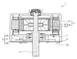
- FIG. 1 It is a block diagram which shows the pump 1 which concerns on Embodiment 1.
- FIG. It is a block diagram which shows the water supply part 2 and the frame 3 which concerns on Embodiment 1.
- FIG. It is a top view which shows the water supply part 2 which concerns on Embodiment 1.
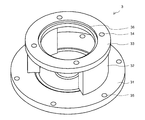
- FIG. It is a perspective view which shows the frame 3 which concerns on Embodiment 1.
- FIG. It is a block diagram which shows the motor part 4, the shaft part 5, the bearing 7 and the bracket 8 which concerns on Embodiment 1.
- FIG. It is a perspective view which shows the motor housing 41 which concerns on Embodiment 1.
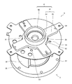
- FIG. It is a perspective view which shows the bracket 8 which concerns on Embodiment 1.
- FIG. It is a block diagram which shows the bracket 8 which concerns on Embodiment 1.
- FIG. It is a block diagram which shows the frame 3 and the bracket 8 which concerns on Embodiment 1.
- FIG. It is a perspective view which shows the sheet metal bracket 9 which concerns on Embodiment 1.
- FIG. It is a perspective view which shows the bracket 8 and the sheet metal bracket 9 which concerns on Embodiment 1.
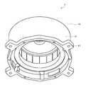
- FIG. It is a perspective view which shows the bracket 208 which concerns on Embodiment 3.
- FIG. 1 is a configuration diagram showing a pump 1 according to the first embodiment. Note that FIG. 1 shows a cross section of the pump 1 in the vertical direction. As shown in FIG. 1, the pump 1 has a water supply unit 2, a frame 3, a motor unit 4, a shaft unit 5, an impeller 6, a bearing 7, a bracket 8, and a sheet metal bracket 9.
- FIG. 2 is a configuration diagram showing a water supply unit 2 and a frame 3 according to the first embodiment.
- FIG. 2 shows a vertical cross section of the water supply unit 2 and the frame 3.
- FIG. 3 is an upper view showing the water supply unit 2 according to the first embodiment.
- the water supply unit 2 applies pressure to a liquid such as water that has flowed into the inside from one pipe 10 connected to the water supply unit 2 and sends the pressure to the other pipe 10.
- the water supply section 2 is formed with a storage space 21, a suction port 22, a discharge port 23, a fitting section 24, and a water supply section fastening hole 25.
- the accommodation space 21 is a space formed inside the water supply unit 2 and accommodates the impeller 6.
- the suction port 22 is an opening formed on the side surface of the water supply portion 2. Further, the suction port 22 communicates with the accommodation space 21. The liquid flowing through one of the pipes 10 flows into the accommodation space 21 through the suction port 22.
- the discharge port 23 is an opening formed on the side surface of the water supply unit 2 facing the suction port 22. Further, the discharge port 23 communicates with the accommodation space 21. The refrigerant that has flowed into the accommodation space 21 flows out to the other pipe 10 through the discharge port 23.
- the fitting portion 24 is a portion formed in the lower part of the accommodation space 21. The lower portion and the outer peripheral side portion of the impeller 6 are fitted to the fitting portion 24.
- the water supply unit fastening hole 25 is six openings formed in the upper part of the water supply unit 2. A bolt or the like is inserted into the water supply portion fastening hole 25 together with the lower fastening hole 34 of the frame 3, which will be described later, and tightened. The number of water supply unit fastening holes 25 does not have to be six.
- FIG. 4 is a perspective view showing the frame 3 according to the first embodiment.
- the frame 3 is an annular member extending in the vertical direction, and includes a lower annular portion 31, a pillar portion 32, and an upper annular portion 33. Further, as shown in FIG. 1, the frame 3 is provided above the water supply unit 2.
- the frame 3 connects the lower portion of the motor portion 4 and the upper portion of the water supply portion 2 via the bracket 8.
- the lower annular portion 31 is an annular member that constitutes the lower portion of the frame 3.
- a lower fastening hole 34 is formed in the lower annular portion 31.
- the lower fastening hole 34 is an opening formed at a position facing the water feeding portion fastening hole 25 on the outer circumference of the lower annular portion 31.
- the pillar portion 32 is a columnar member extending upward from the inner peripheral portion of the lower annular portion 31.
- the upper annular portion 33 is an annular member that connects to the pillar portion 32 and constitutes the upper part of the frame 3.
- An upper fastening hole 35 is formed in the upper annular portion 33.
- the upper fastening hole 35 is four openings formed on the upper surface of the upper annular portion 33.
- a bolt or the like is inserted into the upper fastening hole 35 together with the first fastening hole 93 of the sheet metal bracket 9, which will be described later, and tightened.
- the number of upper fastening holes 35 does not have to be four.
- the upper portion of the upper annular portion 33 is formed so that the inner peripheral surface 36 has an enlarged diameter. That is, a step is formed on the inner peripheral surface 36 of the upper portion of the upper annular portion 33.
- FIG. 5 is a configuration diagram showing a motor unit 4, a shaft unit 5, a bearing 7, and a bracket 8 according to the first embodiment.
- FIG. 5 shows a vertical cross section of the motor portion 4, the shaft portion 5, the bearing 7, and the bracket 8.
- FIG. 6 is a perspective view showing the motor housing 41 according to the first embodiment.
- the motor unit 4 is rotationally driven to rotate the impeller 6.
- the motor unit 4 has a motor housing 41 and a motor unit 42.
- the motor housing 41 is a member that houses the motor unit 42 and forms the outer shell of the motor unit 4.
- the motor housing 41 is formed with a motor fastening hole 43.
- the motor fastening holes 43 are four openings formed in the lower part of the motor housing 41. A bolt or the like is inserted into the motor fastening hole 43 together with the second fastening hole 94 of the sheet metal bracket 9, which will be described later, and tightened.
- the number of motor fastening holes 43 does not have to be four.
- the motor unit 42 rotates the shaft portion 5 and the impeller 6 by being supplied with electric power.
- the motor unit 42 has a stator 44 and a rotor 45.
- the stator 44 is an annular member provided on the inner peripheral surface of the motor housing 41.
- the rotor 45 is a member provided so as to face the inner peripheral surface of the stator 44. The rotor 45 rotates when the stator 44 is energized.
- the shaft portion 5 is a rod-shaped member whose upper portion is inserted into the rotor 45 and whose lower portion is connected to the impeller 6.
- the shaft portion 5 transmits the rotational force of the rotor 45 to the impeller 6 to rotate the impeller 6.
- the impeller 6 is a member housed in the accommodating space 21 and having a vane-shaped plate extending in the radial direction of the water supply portion 2.
- the impeller 6 rotates to apply pressure to the liquid flowing through the accommodation space 21.
- the refrigerant in the accommodation space 21 rotates in the accommodation space 21 and flows, and is sent to the discharge port 23 side.
- the bearing 7 is an annular member provided around the shaft portion 5.
- the bearing 7 is a member that supports the shaft portion 5 and receives a load generated by the rotation of the rotor 45.
- FIG. 7 is a perspective view showing the bracket 8 according to the first embodiment.
- FIG. 8 is a perspective view showing the frame 3, the bracket 8, and the sheet metal bracket 9 according to the first embodiment.
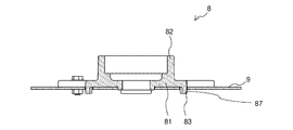
- FIG. 9 is a configuration diagram showing a bracket 8 according to the first embodiment.
- FIG. 9 shows a vertical cross section of the bracket 8.
- the bracket 8 is made of resin, for example, and is an annular member provided around the bearing 7, and supports the shaft portion 5 and the bearing 7.
- the bracket 8 is provided at the lower portion and the inner peripheral portion of the motor portion 4.
- the bracket 8 includes a flat plate portion 81, a bearing housing 82, and a protruding fitting portion 83.
- the flat plate portion 81 is a plate-shaped member having a central disk portion 84 and four extending member portions 85 extending in the radial direction from the central disk portion 84.
- a bracket shaft hole 86 is formed in the center of the disk portion 84.
- the bracket shaft hole 86 is an opening through which the shaft portion 5 is inserted. That is, the diameter of the bracket shaft hole 86 is larger than the diameter of the shaft portion 5.
- the bearing housing 82 is a cylindrical member extending upward from the central portion of the disc portion 84. The bearing housing 82 supports the bearing 7.
- FIG. 10 is a configuration diagram showing a frame 3 and a bracket 8 according to the first embodiment.
- FIG. 10 is an enlarged view of the range surrounded by the dotted line in FIG.
- the protruding fitting portion 83 is a member that protrudes downward from the flat plate portion 81.
- two opposing projecting fitting portions 83 form two sets and project from the edge portion of the disk portion 84.
- the length between the outer peripheral surface 87 of one protruding fitting portion 83 and the outer peripheral surface 87 of the other protruding fitting portion 83 is substantially equal to the inner diameter of the upper annular portion 33 of the frame 3. As a result, as shown in FIG.
- the outer peripheral surface 87 of the protruding fitting portion 83 is fitted to the inner peripheral surface 36 of the upper annular portion 33. That is, the bracket 8 is connected to the frame 3 at an accurate position.
- the position and dimensions of the protruding fitting portion 83 are adjusted only in relation to the frame 3 and are set independently of the motor portion 4. That is, the protruding fitting portions 83 may have a shape other than four as long as they are fitted to the frame 3. Further, the protruding fitting portion 83 may be formed so that the inner peripheral surface of the protruding fitting portion 83 fits on the outer peripheral surface of the upper annular portion 33.
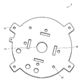
- FIG. 11 is a perspective view showing the sheet metal bracket 9 according to the first embodiment.
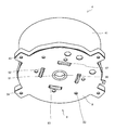
- FIG. 12 is a perspective view showing the bracket 8 and the sheet metal bracket 9 according to the first embodiment.
- the sheet metal bracket 9 has a disk shape. Further, the sheet metal bracket 9 is made of sheet metal.
- the sheet metal bracket 9 is provided between the frame 3 and the motor unit 4 to improve the strength of the pump 1 against vibration or the like generated by driving the motor unit 4.
- the sheet metal bracket 9 is formed with a sheet metal bracket shaft hole 91, an insertion hole 92, a first fastening hole 93, and a second fastening hole 94.
- the sheet metal bracket shaft hole 91 is an opening formed in the central portion of the sheet metal bracket 9.
- the shaft portion 5 is inserted into the sheet metal bracket shaft hole 91. That is, the diameter of the sheet metal bracket shaft hole 91 is larger than the diameter of the shaft portion 5.
- the insertion hole 92 is an opening formed in a rectangular shape. In the first embodiment, four insertion holes 92 are formed. The number and shape of the insertion holes 92 may be changed according to the number and shape of the protruding fitting portions 83. The protruding fitting portion 83 is inserted into the insertion hole 92.
- the first fastening hole 93 is an opening provided at a position facing the upper fastening hole 35. A bolt or the like is inserted into the first fastening hole 93 together with the upper fastening hole 35 and tightened. As a result, the sheet metal bracket 9 is fixed to the frame 3.
- the second fastening hole 94 is an opening provided at a position facing the motor fastening hole 43. A bolt or the like is inserted into the second fastening hole 94 together with the motor fastening hole 43 and tightened. As a result, the motor unit 4 is fixed to the sheet metal bracket 9.
- the operation of the pump 1 will be described.
- the liquid flowing from one of the pipes 10 flows into the accommodation space 21 through the suction port 22.
- pressure is applied to the liquid flowing in the accommodation space 21 by rotating the impeller 6 provided in the accommodation space 21.
- the pressured liquid rotates and flows along the inner peripheral surface of the accommodation space 21.
- the refrigerant flowing through the accommodation space 21 flows out to the other pipe 10 through the discharge port 23.
- the bracket 208 has a fitting portion 24 that fits into the frame 3. Further, a bracket 208 is provided at the lower part of the motor unit 4. That is, the motor portion 4 is connected to the frame 3 via the fitting portion 24 formed on the bracket 208.
- the position and dimensions of the fitting portion 24 are adjusted only in relation to the frame 3 and are set independently of the size of the motor portion 4. Therefore, the position, dimensions, and the like of the fitting portion 24 do not have to be changed even when the motor portion 4 is enlarged in the radial direction. That is, the frame 3 to which the fitting portion 24 is fitted is not expanded in diameter even when the motor portion 4 is enlarged in the radial direction. Therefore, in the pump 201, even when the motor unit 4 is enlarged in the radial direction, the amount of material used for the frame 3 is not increased, and the manufacturing cost can be suppressed.
- the pump 1 can reduce the manufacturing cost by manufacturing the frame 3 using the existing mold.
- the frame 3 and the motor portion 4 are accurately connected via the protruding fitting portion 83 of the bracket 8. Further, the water supply portion 2 and the frame 3 are accurately fixed by bolts or the like tightened in the water supply portion fastening hole 25 and the lower fastening hole 34. That is, the water supply unit 2 and the motor unit 4 are accurately assembled in a state where the coaxiality is small.
- the impeller 6 connected via the motor portion 4 and the shaft portion 5 is accurately fitted to the fitting portion 24 of the water supply portion 2, and a gap is unlikely to occur between the fitting portion 24 and the fitting portion 24. Therefore, the liquid applied under pressure in the accommodation space 21 is suppressed from leaking from between the impeller 6 and the fitting portion 24 to the suction port 22 side.
- the outer peripheral surface 87 of the protruding fitting portion 83 is fitted to the inner peripheral surface 36 of the frame 3. Therefore, the inner diameter of the frame 3 may be adjusted so that the outer peripheral surface 87 of the protruding fitting portion 83 is fitted. Therefore, since the frame 3 of the pump 1 is easily manufactured, the manufacturing cost can be suppressed.
- the pump 1 has a sheet metal bracket 9. Therefore, the pump 1 has improved strength against vibration or the like generated by driving the motor unit 4. Therefore, the pump 1 can cope with an increase in the size of the motor unit 4 in which vibration and the like increase and high strength is required.
- FIG. 13 is a side view showing the bracket 108 according to the second embodiment. Note that FIG. 13 shows a cross section of the bracket 108 in the vertical direction. As shown in FIG. 13, the second embodiment is different from the first embodiment in that the protruding fitting portion 183 is provided at a plurality of positions having different distances from the center of the bracket 108. In the second embodiment, the same parts as those in the first embodiment are designated by the same reference numerals, the description thereof will be omitted, and the differences from the first embodiment will be mainly described.
- Bracket 108 As shown in FIG. 13, the two protruding fitting portions 183 are different in distance from the center of the bracket 108. Therefore, the bracket 108 can be connected to the frames 3 having two different sizes. The number and location of the protruding fitting portions 183 are set within a range that does not interfere with the frame 3.
- the protruding fitting portions 183 are provided at a plurality of positions having different lengths from the center of the bracket 108. Therefore, the bracket 108 can be connected to frames 3 of various sizes. Therefore, the pump 101 can manufacture the frame 3 having different specifications and the water supply unit 2 connected to the frame 3 without increasing the types of the bracket 108, and the manufacturing can be easily controlled.
- FIG. 14 is a configuration diagram showing the pump 201 according to the third embodiment.
- FIG. 14 shows a vertical cross section of the pump 201.
- FIG. 15 is a perspective view showing the bracket 208 according to the third embodiment.
- the third embodiment differs from the first embodiment in that it does not have a sheet metal bracket.
- the third embodiment is different from the first embodiment in that the protruding fitting portion 283 is formed in a circular shape.
- the same parts as those in the first embodiment are designated by the same reference numerals, the description thereof will be omitted, and the differences from the first embodiment will be mainly described.
- the pump 201 does not have a sheet metal bracket.
- the protruding fitting portion 283 is formed in a circular shape whose center coincides with the center of the bracket 208.
- the bracket 208 may have protruding fitting portions 283 formed at a plurality of concentric positions.
- the pump 201 does not have a sheet metal bracket.
- the sheet metal bracket is omitted from the pump 201. Therefore, when the need to improve the strength of the pump 201 is low, the bracket 208 maintains the necessary and sufficient strength even if the sheet metal bracket is omitted. Therefore, the pump 201 can reduce the number of parts while maintaining the necessary and sufficient strength, and can suppress the manufacturing cost.
- the protruding fitting portion 283 is formed in a circular shape whose center coincides with the center of the bracket 208. That is, the protruding fitting portion 283 has a simpler structure. Even in this case, the outer peripheral surface 287 of the protruding fitting portion 283 is fitted to the inner peripheral surface 36 of the upper annular portion 33 of the frame 3. Therefore, in the pump 201, after connecting the frame 3 and the bracket 208, the manufacturing of the protruding fitting portion 283 can be simplified and the manufacturing cost can be suppressed.
Landscapes
- Engineering & Computer Science (AREA)
- Mechanical Engineering (AREA)
- General Engineering & Computer Science (AREA)
- Structures Of Non-Positive Displacement Pumps (AREA)
Priority Applications (2)
| Application Number | Priority Date | Filing Date | Title |
|---|---|---|---|
| JP2022513804A JP7297152B2 (ja) | 2020-04-09 | 2020-04-09 | ポンプ |
| PCT/JP2020/015991 WO2021205607A1 (ja) | 2020-04-09 | 2020-04-09 | ポンプ |
Applications Claiming Priority (1)
| Application Number | Priority Date | Filing Date | Title |
|---|---|---|---|
| PCT/JP2020/015991 WO2021205607A1 (ja) | 2020-04-09 | 2020-04-09 | ポンプ |
Publications (1)
| Publication Number | Publication Date |
|---|---|
| WO2021205607A1 true WO2021205607A1 (ja) | 2021-10-14 |
Family
ID=78022549
Family Applications (1)
| Application Number | Title | Priority Date | Filing Date |
|---|---|---|---|
| PCT/JP2020/015991 Ceased WO2021205607A1 (ja) | 2020-04-09 | 2020-04-09 | ポンプ |
Country Status (2)
| Country | Link |
|---|---|
| JP (1) | JP7297152B2 (https=) |
| WO (1) | WO2021205607A1 (https=) |
Cited By (1)
| Publication number | Priority date | Publication date | Assignee | Title |
|---|---|---|---|---|
| JPWO2023203743A1 (https=) * | 2022-04-22 | 2023-10-26 |
Citations (6)
| Publication number | Priority date | Publication date | Assignee | Title |
|---|---|---|---|---|
| JPS50148102U (https=) * | 1974-05-24 | 1975-12-09 | ||
| JPH079065U (ja) * | 1993-06-25 | 1995-02-07 | 株式会社小糸製作所 | ポンプモータ装置 |
| JPH07177699A (ja) * | 1993-12-22 | 1995-07-14 | Ebara Corp | 片持軸受型モータ及び該モータを使用したポンプ装置 |
| JP2010159696A (ja) * | 2009-01-08 | 2010-07-22 | Tsurumi Mfg Co Ltd | 水中電動ポンプ |
| JP2010275972A (ja) * | 2009-05-29 | 2010-12-09 | Fuji Koki Corp | 排水ポンプ |
| JP2018059497A (ja) * | 2016-09-30 | 2018-04-12 | 株式会社荏原製作所 | モータポンプ及びこれを備える排水設備 |
-
2020
- 2020-04-09 JP JP2022513804A patent/JP7297152B2/ja active Active
- 2020-04-09 WO PCT/JP2020/015991 patent/WO2021205607A1/ja not_active Ceased
Patent Citations (6)
| Publication number | Priority date | Publication date | Assignee | Title |
|---|---|---|---|---|
| JPS50148102U (https=) * | 1974-05-24 | 1975-12-09 | ||
| JPH079065U (ja) * | 1993-06-25 | 1995-02-07 | 株式会社小糸製作所 | ポンプモータ装置 |
| JPH07177699A (ja) * | 1993-12-22 | 1995-07-14 | Ebara Corp | 片持軸受型モータ及び該モータを使用したポンプ装置 |
| JP2010159696A (ja) * | 2009-01-08 | 2010-07-22 | Tsurumi Mfg Co Ltd | 水中電動ポンプ |
| JP2010275972A (ja) * | 2009-05-29 | 2010-12-09 | Fuji Koki Corp | 排水ポンプ |
| JP2018059497A (ja) * | 2016-09-30 | 2018-04-12 | 株式会社荏原製作所 | モータポンプ及びこれを備える排水設備 |
Cited By (3)
| Publication number | Priority date | Publication date | Assignee | Title |
|---|---|---|---|---|
| JPWO2023203743A1 (https=) * | 2022-04-22 | 2023-10-26 | ||
| WO2023203743A1 (ja) | 2022-04-22 | 2023-10-26 | 三菱電機株式会社 | ポンプ |
| EP4513041A4 (en) * | 2022-04-22 | 2025-05-21 | Mitsubishi Electric Corporation | Pump |
Also Published As
| Publication number | Publication date |
|---|---|
| JP7297152B2 (ja) | 2023-06-23 |
| JPWO2021205607A1 (https=) | 2021-10-14 |
Similar Documents
| Publication | Publication Date | Title |
|---|---|---|
| JPWO2019026673A1 (ja) | 回転駆動装置、回転駆動装置の組付方法、軸流送風器、軸流送風器の組付方法及びレーザ発振装置 | |
| KR102125989B1 (ko) | 자기 클러치 펌프 장치 | |
| US8272838B2 (en) | Impeller and pump including the same | |
| CN100590949C (zh) | 轴流风扇电动机 | |
| JP2013036387A (ja) | 回転機械の治具及び回転機械の輸送方法 | |
| CN212717204U (zh) | 磁驱泵浦 | |
| WO2021205607A1 (ja) | ポンプ | |
| WO2018150990A1 (ja) | モータのロータ、モータ、およびポンプ装置 | |
| US20070014677A1 (en) | Pump | |
| KR102803690B1 (ko) | 축방향 자속회전기기 | |
| CN211728944U (zh) | 一种盘式电机定子预装夹具 | |
| WO2019116717A1 (ja) | 排水ポンプ用モータおよびその製造方法、ならびにそのモータを有する排水ポンプ | |
| CN216290507U (zh) | 电动机及电动设备 | |
| JP2020133628A (ja) | 真空装置及び真空システム | |
| US20220010810A1 (en) | Pump Device | |
| CN212272530U (zh) | 电动油泵 | |
| CN118137699A (zh) | 永磁电机、电机转子系统及其制造方法 | |
| JP2020165376A (ja) | 電動オイルポンプ | |
| CN210317907U (zh) | 一种蜗壳及应用该蜗壳的离心风机 | |
| JPH0942193A (ja) | 回転ポンプ及び回転羽根車固定方法 | |
| WO2023203743A1 (ja) | ポンプ | |
| CN216199084U (zh) | 空气压缩机 | |
| CN221299627U (zh) | 风机组件及应用其的热泵系统 | |
| JP2003269375A (ja) | ポンプ装置 | |
| CN210799118U (zh) | 一种汽车电子水泵外壳及具有该外壳的汽车电子水泵 |
Legal Events
| Date | Code | Title | Description |
|---|---|---|---|
| 121 | Ep: the epo has been informed by wipo that ep was designated in this application |
Ref document number: 20930519 Country of ref document: EP Kind code of ref document: A1 |
|
| ENP | Entry into the national phase |
Ref document number: 2022513804 Country of ref document: JP Kind code of ref document: A |
|
| NENP | Non-entry into the national phase |
Ref country code: DE |
|
| 122 | Ep: pct application non-entry in european phase |
Ref document number: 20930519 Country of ref document: EP Kind code of ref document: A1 |