WO2021199803A1 - 電力変換装置 - Google Patents
電力変換装置 Download PDFInfo
- Publication number
- WO2021199803A1 WO2021199803A1 PCT/JP2021/007124 JP2021007124W WO2021199803A1 WO 2021199803 A1 WO2021199803 A1 WO 2021199803A1 JP 2021007124 W JP2021007124 W JP 2021007124W WO 2021199803 A1 WO2021199803 A1 WO 2021199803A1
- Authority
- WO
- WIPO (PCT)
- Prior art keywords
- bus bar
- sensor
- electric
- converter
- electric machine
- Prior art date
- Legal status (The legal status is an assumption and is not a legal conclusion. Google has not performed a legal analysis and makes no representation as to the accuracy of the status listed.)
- Ceased
Links
Images




Classifications
-
- H—ELECTRICITY
- H02—GENERATION; CONVERSION OR DISTRIBUTION OF ELECTRIC POWER
- H02M—APPARATUS FOR CONVERSION BETWEEN AC AND AC, BETWEEN AC AND DC, OR BETWEEN DC AND DC, AND FOR USE WITH MAINS OR SIMILAR POWER SUPPLY SYSTEMS; CONVERSION OF DC OR AC INPUT POWER INTO SURGE OUTPUT POWER; CONTROL OR REGULATION THEREOF
- H02M7/00—Conversion of AC power input into DC power output; Conversion of DC power input into AC power output
- H02M7/42—Conversion of DC power input into AC power output without possibility of reversal
- H02M7/44—Conversion of DC power input into AC power output without possibility of reversal by static converters
- H02M7/48—Conversion of DC power input into AC power output without possibility of reversal by static converters using discharge tubes with control electrode or semiconductor devices with control electrode
- H02M7/53—Conversion of DC power input into AC power output without possibility of reversal by static converters using discharge tubes with control electrode or semiconductor devices with control electrode using devices of a triode or transistor type requiring continuous application of a control signal
- H02M7/537—Conversion of DC power input into AC power output without possibility of reversal by static converters using discharge tubes with control electrode or semiconductor devices with control electrode using devices of a triode or transistor type requiring continuous application of a control signal using semiconductor devices only, e.g. single switched pulse inverters
-
- B—PERFORMING OPERATIONS; TRANSPORTING
- B60—VEHICLES IN GENERAL
- B60L—PROPULSION OF ELECTRICALLY-PROPELLED VEHICLES; SUPPLYING ELECTRIC POWER FOR AUXILIARY EQUIPMENT OF ELECTRICALLY-PROPELLED VEHICLES; ELECTRODYNAMIC BRAKE SYSTEMS FOR VEHICLES IN GENERAL; MAGNETIC SUSPENSION OR LEVITATION FOR VEHICLES; MONITORING OPERATING VARIABLES OF ELECTRICALLY-PROPELLED VEHICLES; ELECTRIC SAFETY DEVICES FOR ELECTRICALLY-PROPELLED VEHICLES
- B60L15/00—Methods, circuits, or devices for controlling the traction-motor speed of electrically-propelled vehicles
- B60L15/32—Control or regulation of multiple-unit electrically-propelled vehicles
-
- H—ELECTRICITY
- H02—GENERATION; CONVERSION OR DISTRIBUTION OF ELECTRIC POWER
- H02K—DYNAMO-ELECTRIC MACHINES
- H02K11/00—Structural association of dynamo-electric machines with electric components or with devices for shielding, monitoring or protection
- H02K11/20—Structural association of dynamo-electric machines with electric components or with devices for shielding, monitoring or protection for measuring, monitoring, testing, protecting or switching
- H02K11/27—Devices for sensing current, or actuated thereby
-
- H—ELECTRICITY
- H02—GENERATION; CONVERSION OR DISTRIBUTION OF ELECTRIC POWER
- H02K—DYNAMO-ELECTRIC MACHINES
- H02K5/00—Casings; Enclosures; Supports
- H02K5/04—Casings or enclosures characterised by the shape, form or construction thereof
- H02K5/22—Auxiliary parts of casings not covered by groups H02K5/06-H02K5/20, e.g. shaped to form connection boxes or terminal boxes
- H02K5/225—Terminal boxes or connection arrangements
-
- H—ELECTRICITY
- H02—GENERATION; CONVERSION OR DISTRIBUTION OF ELECTRIC POWER
- H02M—APPARATUS FOR CONVERSION BETWEEN AC AND AC, BETWEEN AC AND DC, OR BETWEEN DC AND DC, AND FOR USE WITH MAINS OR SIMILAR POWER SUPPLY SYSTEMS; CONVERSION OF DC OR AC INPUT POWER INTO SURGE OUTPUT POWER; CONTROL OR REGULATION THEREOF
- H02M7/00—Conversion of AC power input into DC power output; Conversion of DC power input into AC power output
- H02M7/003—Constructional details, e.g. physical layout, assembly, wiring or busbar connections
-
- H—ELECTRICITY
- H02—GENERATION; CONVERSION OR DISTRIBUTION OF ELECTRIC POWER
- H02M—APPARATUS FOR CONVERSION BETWEEN AC AND AC, BETWEEN AC AND DC, OR BETWEEN DC AND DC, AND FOR USE WITH MAINS OR SIMILAR POWER SUPPLY SYSTEMS; CONVERSION OF DC OR AC INPUT POWER INTO SURGE OUTPUT POWER; CONTROL OR REGULATION THEREOF
- H02M7/00—Conversion of AC power input into DC power output; Conversion of DC power input into AC power output
- H02M7/42—Conversion of DC power input into AC power output without possibility of reversal
- H02M7/44—Conversion of DC power input into AC power output without possibility of reversal by static converters
- H02M7/48—Conversion of DC power input into AC power output without possibility of reversal by static converters using discharge tubes with control electrode or semiconductor devices with control electrode
- H02M7/493—Conversion of DC power input into AC power output without possibility of reversal by static converters using discharge tubes with control electrode or semiconductor devices with control electrode the static converters being arranged for operation in parallel
-
- H—ELECTRICITY
- H02—GENERATION; CONVERSION OR DISTRIBUTION OF ELECTRIC POWER
- H02P—CONTROL OR REGULATION OF ELECTRIC MOTORS, ELECTRIC GENERATORS OR DYNAMO-ELECTRIC CONVERTERS; CONTROLLING TRANSFORMERS, REACTORS OR CHOKE COILS
- H02P5/00—Arrangements specially adapted for regulating or controlling the speed or torque of two or more electric motors
- H02P5/74—Arrangements specially adapted for regulating or controlling the speed or torque of two or more electric motors controlling two or more AC dynamo-electric motors
-
- B—PERFORMING OPERATIONS; TRANSPORTING
- B60—VEHICLES IN GENERAL
- B60L—PROPULSION OF ELECTRICALLY-PROPELLED VEHICLES; SUPPLYING ELECTRIC POWER FOR AUXILIARY EQUIPMENT OF ELECTRICALLY-PROPELLED VEHICLES; ELECTRODYNAMIC BRAKE SYSTEMS FOR VEHICLES IN GENERAL; MAGNETIC SUSPENSION OR LEVITATION FOR VEHICLES; MONITORING OPERATING VARIABLES OF ELECTRICALLY-PROPELLED VEHICLES; ELECTRIC SAFETY DEVICES FOR ELECTRICALLY-PROPELLED VEHICLES
- B60L2240/00—Control parameters of input or output; Target parameters
- B60L2240/40—Drive Train control parameters
- B60L2240/46—Drive Train control parameters related to wheels
- B60L2240/465—Slip
-
- H—ELECTRICITY
- H02—GENERATION; CONVERSION OR DISTRIBUTION OF ELECTRIC POWER
- H02P—CONTROL OR REGULATION OF ELECTRIC MOTORS, ELECTRIC GENERATORS OR DYNAMO-ELECTRIC CONVERTERS; CONTROLLING TRANSFORMERS, REACTORS OR CHOKE COILS
- H02P2201/00—Indexing scheme relating to controlling arrangements characterised by the converter used
- H02P2201/09—Boost converter, i.e. DC-DC step up converter increasing the voltage between the supply and the inverter driving the motor
Definitions
- the present disclosure relates to a power conversion device using a coreless current sensor.
- Patent Document 1 discloses a power conversion device that outputs three-phase alternating current to two motors, a main motor and a sub motor used in a vehicle.
- the power conversion device of Patent Document 1 includes two inverters corresponding to each motor, two sets of bus bassets for transmitting power from each inverter to each motor, and a plurality of current sensors.
- the current flowing through the main bus basset, which transmits power to the main motor is detected by a cored current sensor with a magnetizing core.
- the current flowing through the subbus basset that transmits power to the submotor is detected by a coreless current sensor that does not involve a magnetizing core.
- the power conversion device feedback-controls the output current to each motor by controlling each inverter according to the value detected by each current sensor.
- the coreless current sensor is more advantageous than the cored current sensor in terms of physique and cost.
- the coreless current sensor is more susceptible to the magnetic field generated by the current flowing through another bus bar than the cored current sensor. Therefore, in a power conversion device that supplies electric power to a plurality of motors, if the current flowing through the bus bar is detected by a coreless current sensor, crosstalk is likely to occur with the bus bars of other motors. That is, the detected value of the current sensor of a certain motor tends to be a numerical value obtained by superimposing the frequency component of the current to another motor on the current actually flowing. Therefore, in the power conversion device having the above-described configuration, the output current feedback-controlled according to the detected value may be easily distorted.
- An object of the present disclosure is to provide a power conversion device capable of detecting an output current with a coreless current sensor by suppressing distortion of the output current to a motor.
- the power conversion device of the present disclosure for achieving the above object includes a first inverter connected to a three-phase AC type first rotary electric machine and a second inverter connected to a three-phase AC type second rotary electric machine.
- a converter that converts a DC voltage between a DC power supply, a first inverter and a second inverter, a bus bar for the first electric machine that allows a current to flow between the first inverter and the first rotary electric machine, and a second It is a sensor that detects based on the magnetic field generated by the second electric bus bar that passes the current between the inverter and the second rotating electric machine, the converter bus bar that flows the current of the converter, and the current flowing through the first electric bus bar.
- a coreless type first electric sensor and a control circuit unit that controls the first inverter based on the detected value of the first electric sensor are provided, and the second electric bus bar sandwiches the converter bus bar first. It is located away from the electrical sensor.
- the bus bar for the second electric machine is arranged so as to be separated from the sensor for the first electric machine with the converter bus bar in between. Therefore, the superposition of the frequency component of the three-phase alternating current flowing through the bus bar for the second electric machine with respect to the value detected by the sensor for the first electric machine is suppressed.
- the control unit can operate the first inverter by suppressing the influence of the three-phase alternating current flowing through the second electric bus bar. Therefore, the distortion in the output current from the first inverter to the first rotary electric machine can be suppressed, and the output current can be detected by the coreless current sensor.
- FIG. 3 is a sectional view taken along line IV-IV of FIG. It is a figure which shows the structure of the sensor unit of the modification. It is a figure which shows the structure of the sensor unit of another modification.
- the power conversion device 100 according to the embodiment of the present disclosure will be described with reference to the drawings. First, the circuit configuration of the power conversion device 100 will be described with reference to FIG.
- the power conversion device 100 is used in a vehicle such as a hybrid vehicle equipped with an internal combustion engine and a rotary electric machine as a traveling drive source.
- the electric power conversion device 100 is a device that converts electric power between the first rotary electric machine 1, the second rotary electric machine 2, and the DC power supply 3 in the vehicle.
- the first rotary electric machine 1 and the second rotary electric machine 2 are three-phase AC type rotary electric machines.
- the first rotary electric machine 1 is mainly used as a traveling drive source for a vehicle, for example.
- the second rotary electric machine 2 is used, for example, as a generator that generates electricity mainly by utilizing a rotational driving force output from an internal combustion engine of a vehicle.
- the DC power supply 3 is a power supply unit that outputs a DC voltage, including a rechargeable secondary battery such as a lithium ion battery.
- the power conversion device 100 converts the DC voltage from the DC power supply 3 into a three-phase AC to the first rotating electric machine 1.
- the power conversion device 100 provides a so-called EV drive in which the first rotary electric machine 1 drives the vehicle with the electric power charged in the DC power supply 3.
- the power conversion device 100 converts the three-phase alternating current from the second rotating electric machine 2 generating electricity by the rotational driving force of the internal combustion engine into three-phase alternating current having a different frequency and the like, and converts the three-phase alternating current into the first rotating electric machine. Output to 1.
- the power conversion device 100 provides a so-called HV drive in which the first rotary electric machine 1 drives the vehicle with the electric power generated by using the rotary drive force of the internal combustion engine.
- the uses of the first rotary electric machine 1 and the second rotary electric machine 2 in the vehicle are not limited to those described above, and can be appropriately changed, added, or replaced according to the design of the vehicle to be used. Therefore, the operation of the power conversion device 100 is not limited to that described above, and can be appropriately changed, added, or replaced.
- the power conversion device 100 includes a filter capacitor 110, a converter 120, a smoothing capacitor 130, a first inverter 140a, a second inverter 140b, a sensor unit 160, and a control circuit unit 170.
- the filter capacitor 110 is a capacitor provided between the positive electrode line 10P connected to the positive electrode of the DC power supply 3 and the negative electrode line 10N connected to the negative electrode.
- the filter capacitor 110 functions as a filter for removing noise of the DC voltage supplied from the DC power supply 3 to the converter 120.
- the converter 120 is a conversion circuit unit that converts a DC voltage into a DC voltage having a different value, including a semiconductor switching element and a reactor. In this embodiment, a reverse conduction insulated gate bipolar transistor is used as the semiconductor switching element.
- the converter 120 is used for converting the DC voltage between the DC power supply 3 and the first inverter 140a and the second inverter 140b. As an example, the converter 120 performs an operation of boosting the DC voltage provided as a voltage between the positive electrode line 10P and the negative electrode line 10N from the DC power supply 3.
- the converter 120 has a function of providing the boosted voltage to the first inverter 140a or the like as a voltage between the high potential line 20H and the low potential line 20L.
- the converter 120 has two semiconductor switching elements connected in series between the high potential line 20H and the low potential line 20L. Further, the converter 120 has a reactor 60 arranged to connect a connection point between semiconductor switching elements and a positive electrode line 10P.
- the smoothing capacitor 130 is a capacitor provided between the high potential line 20H and the low potential line 20L.
- the smoothing capacitor 130 has a function of smoothing the voltage provided between the high potential line 20H and the low potential line by boosting the converter 120 or the like.
- the first inverter 140a and the second inverter 140b are conversion circuit units that include a plurality of semiconductor switching elements and perform conversion between a DC voltage and a three-phase alternating current.
- the first inverter 140a and the second inverter 140b are provided with three upper and lower arms having a one-to-one correspondence with three phases.
- the upper and lower arms are arranged in parallel with each other to connect the high potential line 20H and the low potential line 20L.
- Each upper and lower arm includes two semiconductor switching elements connected in series between the high potential line 20H and the low potential line 20L.
- the connection points of the two semiconductor switching elements of each upper and lower arm are connected to the corresponding phases of the rotating electric machine.
- the first inverter 140a is connected to the first rotary electric machine 1.
- the first inverter 140a converts the DC voltage between the high potential line 20H and the low potential line 20L provided by the converter 120 or the like into three-phase alternating current and provides it to the first rotary electric machine 1.
- the second inverter 140b is connected to the second rotary electric machine 2.
- the second inverter 140b rectifies the three-phase alternating current generated by the power generation of the second rotary electric machine 2, for example, and outputs it as a DC voltage between the high potential line 20H and the low potential line 20L.
- the sensor unit 160 is a device for detecting the current flowing through each part of the power conversion device 100.
- the sensor unit 160 detects the current between the first inverter 140a and the first rotary electric machine 1, the current between the second inverter 140b and the second rotary electric machine 2, and the current flowing through the converter 120.
- the specific structure of the sensor unit 160 will be described later.
- the control circuit unit 170 is a group of circuits that exert a function of controlling the operation of the semiconductor switching elements of the converter 120, the first inverter 140a, and the second inverter 140b.
- the control circuit unit 170 is mainly composed of a microcomputer including, for example, a memory for recording software for control and a processor for executing the software.
- the control circuit unit 170 controls the power conversion by controlling the operation of each semiconductor switching element based on the current detected by the sensor unit 160 and the like.
- control circuit unit 170 sets a target fluctuation pattern of the current flowing through each phase of the first rotary electric machine 1 based on the output torque request of the first rotary electric machine 1 from the upper ECU of the vehicle.
- the control circuit unit 170 feedback-controls the first inverter 140a so that the output current from the first inverter 140a to the first rotary electric machine 1 fluctuates along the target fluctuation pattern. That is, the control circuit unit 170 drives each semiconductor switching element of the first inverter 140a based on the output current of the first inverter 140a detected by the sensor unit 160.
- control circuit unit 170 uses the current flowing through the converter 120 to detect wheel slippage and the like.
- the control circuit unit 170 determines that slipping has occurred, for example, when the current flowing through the converter 120 increases by several tens of percent or more with respect to the assumed current. That is, the current flowing through the converter 120 of the present embodiment is used for control that is less susceptible to the influence of crosstalk with the second rotary electric machine 2 as compared with the current to the first rotary electric machine 1.
- the power conversion device 100 includes a plurality of semiconductor devices 40 and a cooler 50 accommodating them. Further, the power conversion device 100 includes a smoothing capacitor 130 and a sensor unit 160 in an arrangement that sandwiches the cooler 50 in the X direction.
- the power conversion device 100 includes a cooler 50, a sensor unit 160, and a reactor 60 arranged on one side in the Y direction with respect to the smoothing capacitor 130.
- the semiconductor device 40 is a device in which a semiconductor switching element and a connecting member for electrically connecting them are integrally packaged by resin sealing or the like.
- Each semiconductor device 40 of the present embodiment is formed in a substantially rectangular plate shape, and includes a semiconductor switching element corresponding to an upper and lower arm for one phase and a connecting member thereof.
- the semiconductor devices 40 are stacked along the Y direction with the refrigerant flow path of the cooler 50 interposed therebetween.
- Each semiconductor device 40 includes three main terminals, a high-potential terminal 41H, a low-potential terminal 41L, and a connection point terminal 41M, respectively.
- the high-potential terminal 41H corresponds to a connection point of the upper and lower arms with the high-potential line 20H.
- the low-potential terminal 41L corresponds to a connection point of the upper and lower arms with the low-potential line 20L.
- the connection point terminal 41M corresponds to an intermediate connection point between the semiconductor switching elements of the upper and lower arms.
- the three main terminals are arranged so as to be arranged along the X direction and project from the surface of the semiconductor device 40 facing the Z direction. The same type of main terminals protruding from different semiconductor devices 40 are arranged along the Y direction.
- the connection point terminals 41M are arranged in an arrangement closest to the sensor unit 160 among the three main terminals.
- the power conversion device 100 of the present embodiment includes seven semiconductor devices 40 constituting a converter 120, a first inverter 140a, and a second inverter 140b. Specifically, the power conversion device 100 includes three first electric devices 40a, three second electric devices 40b, and one converter device 40c.
- Each first electric device 40a constitutes an upper and lower arm corresponding to one phase of the first inverter 140a.
- the first inverter 140a is composed of the three first electric devices 40a. Of the seven semiconductor devices 40 arranged in the Y direction, three from the end far from the reactor 60 correspond to the first electric device 40a.
- Each second electric device 40b constitutes an upper and lower arm corresponding to one phase of the second inverter 140b.
- the second inverter 140b is composed of the three second electric devices 40b. Of the seven semiconductor devices 40 arranged in the Y direction, three from the end closer to the reactor 60 correspond to the second electric device 40b.
- the converter device 40c constitutes the upper and lower arms of the converter 120.
- the converter device 40c constitutes the converter 120 together with the reactor 60.
- the converter device 40c is arranged between each first electric device 40a constituting the first inverter 140a and each second electric device 40b constituting the second inverter 140b.
- each first electric device 40a is arranged so as to be separated from each second electric device 40b with the converter device 40c interposed therebetween.
- the sensor unit 160 is a device in which a bus bar 161 for passing a current to be detected and a current sensor 162 for detecting the current flowing through the bus bar 161 are integrally packaged.
- the sensor unit 160 of the present embodiment also functions as an output terminal block for assembling a connector for connection extending from the first rotary electric machine 1 and the second rotary electric machine 2.
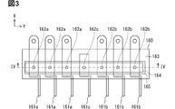
- the sensor unit 160 includes a sensor housing 163, a plurality of bus bars 161 and a plurality of current sensors 162, a sensor substrate 164, and a magnetic shield 165.
- the sensor housing 163 is a member formed of an insulating material such as resin for holding each member constituting the sensor unit 160.
- the sensor housing 163 of the present embodiment is a resin case in which a bus bar 161 and a magnetic shield 165 are embedded by insert molding, and a sensor substrate 164 is housed in an internal storage space.
- the bus bar 161 is a conductive member formed of a conductive material such as copper in a strip shape and passing a current to be detected.
- the sensor unit 160 of the present embodiment has seven bus bars 161 extending in parallel along the X direction and arranged along the Y direction. Therefore, the Y direction corresponds to the "arrangement direction" of the bus bar 161.
- the sensor unit 160 has three first electric bus bars 161a, three second electric bus bars 161b, and one converter bus bar 161c.
- Each bus bar 161 is integrally held by the sensor housing 163 so that the positional relationship with each other is maintained. A part of both ends of each bus bar 161 is exposed to the outside of the sensor housing 163 for electrical and mechanical connection. One end of each bus bar 161 projects from the sensor housing 163 toward the corresponding semiconductor device 40 to be connected along the X direction.
- Each bus bar 161 extends at least a part of a portion located inside the sensor housing 163 along the X direction in a posture in which the main surface faces the Z direction.
- the portion of the posture in which the main surface is directed in the Z direction is the portion to be detected by the current sensor 162.
- Each bus bar 161 is arranged so that at least a part of the detected portion overlaps with each other in the projection view in the Y direction.
- the arrangement order in the Y direction in the detected portion of each bus bar 161 matches the arrangement order in the Y direction of the corresponding semiconductor devices 40.
- the first electric bus bar 161a is three of the seven bus bars 161 arranged in the Y direction from the end far from the reactor 60. One end of each first electric bus bar 161a is connected to the connection point terminal 41M of the corresponding first electric device 40a by welding or the like.
- the bus bar 161a for the first electric machine and the device 40a for the first electric machine correspond to each other in the same arrangement order in the Y direction. More specifically, the bus bar 161a for the first electric machine and the device 40a for the first electric machine correspond to each other on the side far from the reactor 60, the second from the end, and the third from the end.
- each bus bar 161a for the first electric machine is a terminal that protrudes from the sensor housing 163 and to which the connector of the first rotary electric machine 1 is connected. Therefore, the bus bar 161a for the first electric machine electrically connects the first inverter 140a and the first rotary electric machine 1. For example, when the HV is driven, the three-phase alternating current output from the first inverter 140a to the first rotary electric machine 1 flows through the bus bar 161a for the first electric machine. In this case, a magnetic field whose strength and direction change periodically according to the frequency of the three-phase alternating current provided to the first rotary electric machine 1 is generated from each bus bar 161a for the first electric machine.
- the second electric bus bar 161b is three of the seven bus bars 161 arranged in the Y direction from the end closer to the reactor 60. One end of each second electric machine bus bar 161b is connected to the connection point terminal 41M of the corresponding second electric device 40b by welding or the like.
- the bus bar 161b for the second electric machine and the device 40b for the second electric machine correspond to each other in the same arrangement order in the Y direction. More specifically, the bus bar 161b for the second electric machine and the device 40b for the second electric machine correspond to each other on the side close to the reactor 60, the second from the end, and the third from the end.
- each second electric machine bus bar 161b protrudes from the sensor housing 163 as a terminal for connecting to the connector of the second rotary electric machine 2. Therefore, the second electric machine bus bar 161b electrically connects the second inverter 140b and the second rotary electric machine 2.
- the three-phase alternating current output from the second rotating electric machine 2 generating electricity to the second inverter 140b flows through the bus bar 161b for the second electric machine.
- a magnetic field whose strength and direction change periodically according to the frequency of the three-phase alternating current determined according to the rotation speed of the second rotary electric machine 2 is generated.
- the converter bus bar 161c is located in the center of the seven bus bars 161 arranged in the Y direction.
- One end of the converter bus bar 161c is electrically and mechanically connected to the connection point terminal 41M of the corresponding converter device 40c by welding or the like.
- the other end of the converter bus bar 161c is exposed from the sensor housing 163 so that it can be directly or indirectly connected to one end of the reactor 60.
- the other end of the converter bus bar 161c of the present embodiment protrudes from the sensor housing 163 in the Z direction at a position between the first electric bus bar 161a and the second electric bus bar 161b in the Y direction.
- the other end protruding from the sensor housing 163 extends toward the reactor 60 along the Y direction outside the sensor housing 163, and is connected to the reactor 60 by welding or the like. Therefore, the converter bus bar 161c electrically connects the connection points between the semiconductor switching elements of the converter 120 and the reactor 60.
- the current flowing through the reactor 60 of the converter 120 flows through the converter bus bar 161c. Therefore, a current that can be regarded as a direct current having a substantially constant direction and magnitude flows through the converter bus bar 161c according to the power supply relationship between the direct current power supply 3 and the power converter 100. Therefore, the converter bus bar 161c generates a magnetic field having a smaller change in direction and magnitude with the passage of time as compared with the magnetic field generated from the second electric bus bar 161b.
- the current sensor 162 is a device that detects the current flowing through each bus bar 161 by detecting the strength of the magnetic field generated by the current.
- the current sensor 162 is a sensor package including a semiconductor substrate on which a magnetoelectric conversion element such as a magnetoresistive effect element is formed.
- the current sensor 162 outputs, for example, a detection value indicating the strength and direction of the magnetic field along a predetermined detection axis at its own position as an electric signal.
- Each current sensor 162 is mounted on the sensor board 164 in an arrangement arranged along the Y direction.
- the electric signal output from each current sensor 162 is transmitted to the control circuit unit 170 via a common signal connector mounted on the sensor board 164.
- the pitch in the Y direction of each current sensor 162 is set according to the pitch in the Y direction of the bus bar 161.
- Each current sensor 162 is arranged in a predetermined positional relationship with respect to the corresponding bus bar 161 by assembling the sensor substrate 164 to the sensor housing 163 that holds each bus bar 161. Specifically, each current sensor 162 faces the portion of the corresponding bus bar 161 whose main surface faces in the Z direction in an arrangement arranged along the Z direction.
- each current sensor 162 detects a magnetic field at a position facing the main surface of the bus bar 161 facing the Z direction, which is generated by a current flowing in the X direction. Each current sensor 162 directly detects the generated magnetic field.
- No members made of magnetic material are arranged on both sides of each current sensor 162 in the Y direction.
- a member made of a magnetic material is not arranged between the current sensor 162 and the bus bar 161 adjacent to the bus bar 161 corresponding to the current sensor 162. That is, all the current sensors 162 of the sensor unit 160 are configured as coreless current sensors without a magnetic collecting core surrounding the corresponding bus bar 161. Therefore, the magnetic field detected by each current sensor 162 is partially superposed with the component of the magnetic field generated from the bus bar 161 adjacent to the corresponding bus bar 161. That is, the components attenuated according to the separation distance of the adjacent bus bars 161 and the angle with respect to the detection axis are superimposed on each current sensor 162.
- the sensor unit 160 includes seven current sensors 162. Specifically, the sensor unit 160 includes three sensors 162a for the first electric machine, three sensors 162b for the second electric machine, and a sensor 162c for the converter.
- the sensor 162a for the first electric machine has a one-to-one correspondence with the bus bar 161a for the first electric machine, respectively.
- the first electric machine sensor 162a detects the current flowing through the corresponding first electric machine bus bar 161a. Therefore, the sensor 162a for the first electric machine is arranged in the Y direction so as to be separated from the bus bar 161b for the second electric machine with the converter bus bar 161c interposed therebetween. That is, the converter bus bar 161c is arranged between the position where the sensor 162a for the first electric machine is projected and the bus bar 161b for the second electric machine on the plane where the converter bus bar 161c and the bus bar 161b for the second electric machine are lined up. ing. In other words, the second electric machine bus bar 161b is arranged so as to be separated from the converter bus bar 161c with the converter bus bar 161c interposed therebetween with respect to the first electric machine sensor 162a.
- the sensor 162a for the first electric machine which is the closest to the bus bar 161b for the second electric machine among the three, is in a state adjacent to the converter bus bar 161c instead of the bus bar 161b for the second electric machine. Therefore, the component due to the current flowing through the adjacent bus bar 161 superimposed on the detection value of the first electric sensor 162a has a direction and magnitude with the passage of time as compared with the case where the current flows in the adjacent bus bar 161b. Fluctuations are suppressed. That is, the waveform of the detected current is less likely to be distorted. As a result, it is possible to suppress the distortion of the waveform while suppressing the increase in the body size of the sensor unit 160 due to the increase in the distance between the first electric bus bar 161a and the second electric bus bar 161b.
- the sensor 162b for the second electric machine has a one-to-one correspondence with the bus bar 161b for the second electric machine, respectively.
- the second electric machine sensor 162b detects the current flowing through the corresponding second electric machine bus bar 161b.
- the second electric machine sensor 162b is arranged in the Y direction so as to be separated from the first electric machine bus bar 161a with the converter bus bar 161c interposed therebetween.
- the converter sensor 162c corresponds to the converter bus bar 161c and detects the current flowing through the converter bus bar 161c.
- the converter sensor 162c is arranged between the first electric sensor 162a and the second electric sensor 162b that are adjacent to each other in the Y direction. That is, in the projection view in the direction in which the first electric sensor 162a and the second electric sensor 162b are arranged side by side, at least a part of the first electric sensor 162a and the second electric sensor 162b overlap with the first electric sensor 162a and the second electric sensor 162b.
- the component due to the current of the adjacent bus bars 161 on both sides is partially superimposed on the detected value of the converter sensor 162c. That is, the AC components of the first electric bus bar 161a and the second electric bus bar 161b are superimposed to form a direct current including a pulsating current component. As described above, the current detected by the converter sensor 162c is unlikely to have a substantial effect on the control in the control circuit unit 170 even if it contains such a pulsating current component.
- the magnetic shield 165 is formed in a plate shape by a magnetic material, and is arranged in a posture in which both sides face the Z direction.
- the magnetic shield 165 is arranged on the side opposite to each bus bar 161 for each current sensor 162 and on the side opposite to each current sensor 162 for each bus bar 161 in the Z direction.
- Each magnetic shield 165 of the present embodiment is formed in a strip shape extending along the Y direction, and is provided so as to cover all seven current sensors 162 in the projection view in the Z direction.
- Each magnetic shield 165 suppresses the influence of the external magnetic field of the sensor unit 160 on the detected value of the current sensor 162.
- the magnetic shield 165 may be divided in the Y direction and individually provided for each current sensor 162.
- the second electric machine bus bar 161b is arranged so as to be separated from the first electric machine sensor 162a with the converter bus bar 161c interposed therebetween. Therefore, the superposition of the frequency component of the three-phase alternating current flowing through the bus bar 161b for the second electric machine with respect to the value detected by the sensor 162a for the first electric machine is suppressed.
- the control circuit unit 170 controls the first inverter 140a based on the detected value of the first electric sensor 162a to suppress the influence of the three-phase alternating current flowing through the second electric bus bar 161b and suppress the influence of the three-phase alternating current to the first inverter 140a. Can be operated. Therefore, the distortion in the output current from the first inverter 140a to the first rotary electric machine 1 can be suppressed, and the output current can be detected by the coreless current sensor 162.
- the converter sensor 162c is arranged between the first electric sensor 162a and the second electric sensor 162b. Contrary to the above configuration, when the converter sensor 162c is arranged at another position, the body size of the sensor unit 160 may be increased due to the increase or expansion of other members such as the magnetic shield 165. In response to such concerns, in the present embodiment, the converter sensor 162c is arranged so as to be able to suppress the increase and expansion of other members. Therefore, the power conversion device 100 can suppress the increase in the physique of the sensor unit 160 while suppressing the influence on the control based on the current detected by the sensor unit 160.
- each semiconductor device 40 of the present embodiment has the same arrangement order as the arrangement order of the connected bus bars 161 in the Y direction. Contrary to the above configuration, when the arrangement order of the semiconductor device 40 is different from the arrangement order of the portion of the bus bar 161 facing the current sensor 162, some bus bars 161 bypass the other bus bars 161 and correspond to the semiconductor device. It will be connected to 40, and an increase in physique may occur. In response to such concerns, in the present embodiment, each bus bar 161 can be connected to the corresponding semiconductor device 40 without bypassing the other bus bars 161. Therefore, the power conversion device can arrange the second electric bus bar 161b away from the first electric sensor 162a while suppressing the increase in the physique of each bus bar 161.
- all of the current sensors 162 are integrally held with the bus bars 161 by the sensor housing 163. Contrary to the above configuration, when each current sensor 162 is individually attached to each bus bar 161, the number of parts and the physique of the entire sensor unit 160 are increased. In response to such concerns, in the present embodiment, the sensor housing 163 held integrally makes it possible to attach each current sensor 162 to each bus bar 161 while suppressing an increase in the number of parts and the physique.
- the power converter 100 includes two inverters connected to two rotary electric machines, respectively, and uses a single-phase converter as the converter 120.
- the semiconductor device 40 constituting them includes a semiconductor switching element corresponding to each of the upper and lower arms of one phase and a connecting member thereof.
- seven semiconductor devices 40, seven bus bars 161 and seven current sensors 162 are provided.
- the current sensor corresponding to the bus bar to one of the rotary electric machines and the bus bar 161 to the other rotary electric machine are arranged apart from each other with the converter bus bar 161c in between, the configuration of the power converter 100 is limited to this. I can't.
- the power conversion device 100 can adopt a configuration further including a third inverter connected to the third rotary electric machine.
- a third electric bus bar 161d connecting them and a third electric sensor 162d for detecting the current flowing through the bus bar 161d are further provided.
- the converter bus bar 161c may not be arranged between the sensor 162d for the third electric machine and the bus bar 161b for the second electric machine. That is, as long as the converter bus bar 161c is arranged between the bus bar 161 of one of the rotary electric machines and the current sensor 162 of the other rotary electric machine, the arrangement relationship in the pair of the other rotary electric machines does not matter.
- a plurality of converter buses 161c are provided.
- the bus bar 161 of any rotary electric machine can be arranged in a nested manner between the two converter bus bars 161c. That is, as shown in FIG. 6, three second electric bus bars 161b are arranged between the two converter bus bars 161c, three first electric bus bars 161a on one of the outer sides, and three third electric machines on the other.
- a bus bar 161d for use can be arranged.
- a plurality of converter bus bars 161c are provided, they can be arranged between the bus bars 161 for a rotary electric machine in a state of being adjacent to each other.
- each semiconductor device 40 and each bus bar 161 may have a different arrangement order.
- each bus bar 161 may be in a state where at least a part thereof is not parallel to each other.
- the first electric sensor 162a is provided one-to-one on all of the three first electric bus bars 161a.
- the first electric sensor 162a and the second electric bus bar 161b that are closest to the second electric bus bar 161b A converter bus bar 161c may be provided between them.
Landscapes
- Engineering & Computer Science (AREA)
- Power Engineering (AREA)
- Microelectronics & Electronic Packaging (AREA)
- Transportation (AREA)
- Mechanical Engineering (AREA)
- Inverter Devices (AREA)
Priority Applications (3)
| Application Number | Priority Date | Filing Date | Title |
|---|---|---|---|
| DE112021002013.7T DE112021002013T5 (de) | 2020-03-31 | 2021-02-25 | Stromrichter |
| CN202180024542.0A CN115380464A (zh) | 2020-03-31 | 2021-02-25 | 电力转换装置 |
| US17/954,693 US12166429B2 (en) | 2020-03-31 | 2022-09-28 | Power converter |
Applications Claiming Priority (2)
| Application Number | Priority Date | Filing Date | Title |
|---|---|---|---|
| JP2020062638A JP7415742B2 (ja) | 2020-03-31 | 2020-03-31 | 電力変換装置 |
| JP2020-062638 | 2020-03-31 |
Related Child Applications (1)
| Application Number | Title | Priority Date | Filing Date |
|---|---|---|---|
| US17/954,693 Continuation US12166429B2 (en) | 2020-03-31 | 2022-09-28 | Power converter |
Publications (1)
| Publication Number | Publication Date |
|---|---|
| WO2021199803A1 true WO2021199803A1 (ja) | 2021-10-07 |
Family
ID=77929586
Family Applications (1)
| Application Number | Title | Priority Date | Filing Date |
|---|---|---|---|
| PCT/JP2021/007124 Ceased WO2021199803A1 (ja) | 2020-03-31 | 2021-02-25 | 電力変換装置 |
Country Status (5)
| Country | Link |
|---|---|
| US (1) | US12166429B2 (https=) |
| JP (1) | JP7415742B2 (https=) |
| CN (1) | CN115380464A (https=) |
| DE (1) | DE112021002013T5 (https=) |
| WO (1) | WO2021199803A1 (https=) |
Cited By (4)
| Publication number | Priority date | Publication date | Assignee | Title |
|---|---|---|---|---|
| US12025640B2 (en) | 2020-03-31 | 2024-07-02 | Denso Corporation | Current detection device |
| US12081137B2 (en) | 2020-03-31 | 2024-09-03 | Denso Corporation | Power converter |
| US12166429B2 (en) | 2020-03-31 | 2024-12-10 | Denso Corporation | Power converter |
| WO2025182891A1 (ja) * | 2024-02-27 | 2025-09-04 | 新電元工業株式会社 | 電子装置 |
Families Citing this family (2)
| Publication number | Priority date | Publication date | Assignee | Title |
|---|---|---|---|---|
| DE112021008024B4 (de) * | 2021-07-27 | 2025-11-06 | Mitsubishi Electric Corporation | Verdrahtungskomponente für elektrische geräte |
| US12283805B2 (en) * | 2023-03-30 | 2025-04-22 | BorgWarner US Technologies LLC | Bus bar assembly |
Citations (2)
| Publication number | Priority date | Publication date | Assignee | Title |
|---|---|---|---|---|
| JP2012191768A (ja) * | 2011-03-11 | 2012-10-04 | Denso Corp | 電力変換装置 |
| JP2018068096A (ja) * | 2016-10-14 | 2018-04-26 | 株式会社デンソー | 電流センサ装置 |
Family Cites Families (18)
| Publication number | Priority date | Publication date | Assignee | Title |
|---|---|---|---|---|
| JP4998836B2 (ja) * | 2009-09-30 | 2012-08-15 | 株式会社デンソー | 多相回転機の制御装置、および、これを用いた電動パワーステアリング装置 |
| JP5560232B2 (ja) * | 2011-04-28 | 2014-07-23 | トヨタ自動車株式会社 | 電流検出装置 |
| JP5564014B2 (ja) * | 2011-06-28 | 2014-07-30 | トヨタ自動車株式会社 | 電力変換装置及びそれを備えた電動車両 |
| JP5652434B2 (ja) * | 2012-06-15 | 2015-01-14 | 株式会社デンソー | モータ制御装置、及び、これを用いた電動パワーステアリング装置 |
| JP6168609B2 (ja) | 2012-06-20 | 2017-07-26 | アクアインテック株式会社 | 移送システム |
| JP6036585B2 (ja) | 2013-07-17 | 2016-11-30 | 株式会社デンソー | 電力変換装置 |
| DE112014002740T5 (de) * | 2013-07-23 | 2016-03-31 | Aisin Aw Co., Ltd. | Antriebsvorrichtung |
| JP2015186317A (ja) | 2014-03-24 | 2015-10-22 | トヨタ自動車株式会社 | 電力変換装置 |
| JP6248860B2 (ja) | 2014-08-08 | 2017-12-20 | トヨタ自動車株式会社 | 電動車両用の電力変換器 |
| JP2018185230A (ja) | 2017-04-26 | 2018-11-22 | 株式会社デンソー | 電流センサ |
| JP6780583B2 (ja) | 2017-05-18 | 2020-11-04 | 株式会社デンソー | 電力変換装置 |
| US11239761B2 (en) * | 2018-01-24 | 2022-02-01 | Infineon Technologies Ag | Coreless current sensor for high current power module |
| JP6452871B1 (ja) | 2018-02-23 | 2019-01-16 | 三菱電機株式会社 | 電子部品収容構造体 |
| JP2021164243A (ja) | 2020-03-31 | 2021-10-11 | 株式会社デンソー | 電力変換装置 |
| JP7415742B2 (ja) | 2020-03-31 | 2024-01-17 | 株式会社デンソー | 電力変換装置 |
| JP7322786B2 (ja) | 2020-03-31 | 2023-08-08 | 株式会社デンソー | 電力変換装置 |
| JP7279676B2 (ja) | 2020-03-31 | 2023-05-23 | 株式会社デンソー | 電流検出装置、および、電流検出方法 |
| JP7218746B2 (ja) | 2020-03-31 | 2023-02-07 | 株式会社デンソー | 電流検出装置 |
-
2020
- 2020-03-31 JP JP2020062638A patent/JP7415742B2/ja active Active
-
2021
- 2021-02-25 WO PCT/JP2021/007124 patent/WO2021199803A1/ja not_active Ceased
- 2021-02-25 CN CN202180024542.0A patent/CN115380464A/zh active Pending
- 2021-02-25 DE DE112021002013.7T patent/DE112021002013T5/de active Pending
-
2022
- 2022-09-28 US US17/954,693 patent/US12166429B2/en active Active
Patent Citations (2)
| Publication number | Priority date | Publication date | Assignee | Title |
|---|---|---|---|---|
| JP2012191768A (ja) * | 2011-03-11 | 2012-10-04 | Denso Corp | 電力変換装置 |
| JP2018068096A (ja) * | 2016-10-14 | 2018-04-26 | 株式会社デンソー | 電流センサ装置 |
Cited By (4)
| Publication number | Priority date | Publication date | Assignee | Title |
|---|---|---|---|---|
| US12025640B2 (en) | 2020-03-31 | 2024-07-02 | Denso Corporation | Current detection device |
| US12081137B2 (en) | 2020-03-31 | 2024-09-03 | Denso Corporation | Power converter |
| US12166429B2 (en) | 2020-03-31 | 2024-12-10 | Denso Corporation | Power converter |
| WO2025182891A1 (ja) * | 2024-02-27 | 2025-09-04 | 新電元工業株式会社 | 電子装置 |
Also Published As
| Publication number | Publication date |
|---|---|
| DE112021002013T5 (de) | 2023-01-26 |
| JP2021164244A (ja) | 2021-10-11 |
| CN115380464A (zh) | 2022-11-22 |
| JP7415742B2 (ja) | 2024-01-17 |
| US20230012536A1 (en) | 2023-01-19 |
| US12166429B2 (en) | 2024-12-10 |
Similar Documents
| Publication | Publication Date | Title |
|---|---|---|
| JP7415742B2 (ja) | 電力変換装置 | |
| CN115335709B (zh) | 电流检测装置 | |
| JP7133519B2 (ja) | 電力変換装置 | |
| JP7127633B2 (ja) | センサユニット | |
| US12081137B2 (en) | Power converter | |
| JPWO2018180897A1 (ja) | インバータユニット | |
| JP7124530B2 (ja) | 電力変換装置 | |
| US11333687B2 (en) | Sensor unit | |
| JP2020202633A (ja) | 電力制御装置及び駆動ユニット | |
| CN110323952B (zh) | 电力转换装置 | |
| JP2021164242A (ja) | 電力変換装置 | |
| JP7334658B2 (ja) | 電力変換装置 | |
| US11293990B2 (en) | Sensor unit | |
| JP4385883B2 (ja) | 半導体モジュール | |
| JP5919424B1 (ja) | コンデンサモジュール | |
| JP6241098B2 (ja) | 車載用モータ制御装置 | |
| JP7167862B2 (ja) | センサユニット | |
| JP7318418B2 (ja) | 電力変換器 | |
| JP2020039242A (ja) | 駆動ユニット | |
| CN110336481A (zh) | 电力转换装置和电力转换装置用电容器 | |
| JP7180455B2 (ja) | 電力変換ユニット | |
| CN116896280A (zh) | 电力转换装置 | |
| JP2019071363A (ja) | 電力変換装置 | |
| CN115473421A (zh) | 放电装置 | |
| JP2023172011A (ja) | 電力変換装置 |
Legal Events
| Date | Code | Title | Description |
|---|---|---|---|
| 121 | Ep: the epo has been informed by wipo that ep was designated in this application |
Ref document number: 21781376 Country of ref document: EP Kind code of ref document: A1 |
|
| 122 | Ep: pct application non-entry in european phase |
Ref document number: 21781376 Country of ref document: EP Kind code of ref document: A1 |