WO2021186686A1 - 携帯端末 - Google Patents
携帯端末 Download PDFInfo
- Publication number
- WO2021186686A1 WO2021186686A1 PCT/JP2020/012372 JP2020012372W WO2021186686A1 WO 2021186686 A1 WO2021186686 A1 WO 2021186686A1 JP 2020012372 W JP2020012372 W JP 2020012372W WO 2021186686 A1 WO2021186686 A1 WO 2021186686A1
- Authority
- WO
- WIPO (PCT)
- Prior art keywords
- heat
- metal structure
- main body
- vapor chamber
- mobile terminal
- Prior art date
- Legal status (The legal status is an assumption and is not a legal conclusion. Google has not performed a legal analysis and makes no representation as to the accuracy of the status listed.)
- Ceased
Links
Images





Classifications
-
- F—MECHANICAL ENGINEERING; LIGHTING; HEATING; WEAPONS; BLASTING
- F28—HEAT EXCHANGE IN GENERAL
- F28D—HEAT-EXCHANGE APPARATUS, NOT PROVIDED FOR IN ANOTHER SUBCLASS, IN WHICH THE HEAT-EXCHANGE MEDIA DO NOT COME INTO DIRECT CONTACT
- F28D15/00—Heat-exchange apparatus with the intermediate heat-transfer medium in closed tubes passing into or through the conduit walls ; Heat-exchange apparatus employing intermediate heat-transfer medium or bodies
- F28D15/02—Heat-exchange apparatus with the intermediate heat-transfer medium in closed tubes passing into or through the conduit walls ; Heat-exchange apparatus employing intermediate heat-transfer medium or bodies in which the medium condenses and evaporates, e.g. heat pipes
-
- H—ELECTRICITY
- H04—ELECTRIC COMMUNICATION TECHNIQUE
- H04M—TELEPHONIC COMMUNICATION
- H04M1/00—Substation equipment, e.g. for use by subscribers
- H04M1/02—Constructional features of telephone sets
-
- H—ELECTRICITY
- H05—ELECTRIC TECHNIQUES NOT OTHERWISE PROVIDED FOR
- H05K—PRINTED CIRCUITS; CASINGS OR CONSTRUCTIONAL DETAILS OF ELECTRIC APPARATUS; MANUFACTURE OF ASSEMBLAGES OF ELECTRICAL COMPONENTS
- H05K7/00—Constructional details common to different types of electric apparatus
- H05K7/20—Modifications to facilitate cooling, ventilating, or heating
Definitions
- the present invention relates to a mobile terminal.
- Patent Document 1 describes a mobile terminal in which a rechargeable battery is attached to a metal frame with a heat conductive double-sided tape.
- Patent Document 2 describes a liquid crystal display device for a projector in which a liquid crystal panel is fixed to a metal plate with a high thermal conductive double-sided tape.
- 5G 5th generation mobile communication system
- 3GPP Third Generation Partnership Project
- One aspect of the disclosed technology is to provide a mobile terminal that can be easily thinned and can easily control heat conduction from heat generating parts.
- the portable terminal has a vapor chamber having a heat-generating component, a main body that encloses a fluid that transports heat, and comes into contact with the heat-generating component, and a protruding portion that protrudes from the edge of the bottom of the main body, and the main body.
- the plate-shaped metal structure having a through hole into which the metal structure is inserted and the protruding portion arranged so as to overlap the metal structure in the normal direction of the metal structure are bonded to the metal structure.
- a heat conductive adhesive member is provided, and a gap is formed between the main body and the metal structure, and the heat conductive adhesive member conducts heat from the heat generating component to the metal structure. Arranged according to.
- the disclosed technology is easy to reduce in thickness and can easily control the conduction of heat from heat generating parts.
- FIG. 1 is a diagram showing an exploded perspective view of a smartphone according to an embodiment.
- FIG. 2 is a cross-sectional view taken along the line AA of FIG.
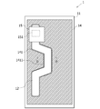
- FIG. 3 is a diagram illustrating a state in which the rear cover of the smartphone according to the embodiment is removed.
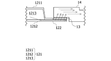
- FIG. 4 is an end view taken along the line BB of FIG.
- FIG. 5 is a diagram schematically showing heat conduction from the vapor chamber to the heat sink in the embodiment.
- FIG. 6 is a diagram schematically showing the transfer of heat from the electronic component in the embodiment to the heat sink via the vapor chamber.
- FIG. 7 is a first diagram schematically showing a difference in heat conduction due to a difference in the width of the heat conductive double-sided tape.
- FIG. 8 is a second diagram schematically showing the difference in heat conduction due to the difference in the width of the heat conductive double-sided tape.
- the mobile terminal according to the embodiment has, for example, the following configuration.
- the mobile terminal according to this embodiment is Heat-generating parts and A vapor chamber in which a fluid that transports heat is sealed and has a main body portion that comes into contact with the heat generating component and a protruding portion that protrudes from the edge of the bottom portion of the main body portion.
- a heat conductive adhesive member for adhering the protruding portion arranged so as to overlap the metal structure in the normal direction of the metal structure to the metal structure is provided.
- a gap is formed between the main body and the metal structure.
- the heat conductive adhesive member is arranged according to the amount of heat conducted from the heat generating component to the metal structure.
- the mobile terminal according to the embodiment is a portable information processing device that can be carried by the user.
- the portable information processing device include a feature phone, a smartphone, a tablet computer, a wearable computer, a notebook computer, and the like.
- the heat-generating component is a component that generates heat in a mobile terminal.
- Examples of the heat generating component include a processor, a memory, a secondary battery, an antenna device, and the like.
- the vapor chamber is a heat pipe in which both the main body and the protruding portion are formed in a flat plate shape by a thin metal plate.
- the vapor chamber is formed thinner than the heat pipes conventionally used. Since the vapor chamber provides a space for enclosing the fluid that transports heat, the main body portion is thicker than the protruding portion. If the main body having such a thickness is arranged so as to be superposed on the metal structure in order to conduct heat from the vapor chamber to the metal structure, it becomes difficult to reduce the thickness of the mobile terminal. Therefore, in the present embodiment, the main body is inserted into the through hole provided in the plate-shaped metal structure.
- the protruding portion protruding from the bottom edge of the main body is arranged so as to overlap the metal structure in the normal direction of the metal structure, and the protruding portion and the metal structure are placed on the thermally conductive adhesive member. By adhering with, heat conduction from the vapor chamber to the metal structure is realized. By inserting the thick main body into the through hole of the metal structure, it is possible to easily reduce the thickness of the mobile terminal.
- the metal structure is made of metal, it has high thermal conductivity, and it is easy to diffuse the heat conducted from the vapor chamber. Further, in the present embodiment, the metal structure may be in contact with the inner wall surface of the housing of the mobile terminal. When the metal structure comes into contact with the inner wall surface of the housing, the metal structure can support the housing from the inside. Therefore, the rigidity of the mobile terminal is increased.
- the heat conductive adhesive member various members can be used as long as they have high thermal conductivity and can bond the protruding portion and the metal structure.
- the heat conductive adhesive member may be, for example, a double-sided tape having a high thermal conductivity or an adhesive having a high thermal conductivity.
- the thermally conductive adhesive member may be a member having a high thermal conductivity and may be a member for welding the protruding portion and the metal structure.
- the amount of heat conducted from the heat generating component to the metal structure can be controlled by arranging the heat conductive adhesive member that adheres the protruding portion and the metal structure.
- a heat conductive adhesive member having a wider width in a portion where more heat is desired to be conducted from a heat generating component to a metal structure or a heat conductive adhesive member having a high thermal conductivity and a protruding portion and a metal structure. And just adhere.
- a heat conductive adhesive member formed with a narrow width or a heat conductive adhesive member having a low thermal conductivity is used to form a protruding portion and the metal structure. Or may not be bonded by the heat conductive adhesive member.
- the heat conductive adhesive member is arranged in a portion that promotes heat conduction from the heat generating component with a first width, and is arranged in a portion that suppresses heat conduction from the heat generating component. It may be arranged with a second width wider than the width.
- the vapor chamber may come into contact with the heat generating component in a part of the main body. That is, at least a part of the vapor chamber does not come into contact with heat generating parts.
- the vapor chamber can easily conduct the heat from the heat generating component to the region where the heat generating component is not mounted.
- FIG. 1 is a diagram showing an exploded perspective view of a smartphone according to an embodiment.
- the smartphone 1 is a portable information processing device capable of wireless communication.
- the smartphone 1 includes a front cover 11, a vapor chamber 12, a heat conductive double-sided tape 13, a heat sink 14, a substrate 15, and a rear cover 16.
- Smartphone 1 is a portable information processing device.
- the front cover 11 and the rear cover 16 are housings for the smartphone 1.
- a display, a speaker, and a microphone are mounted on the front cover 11.
- a rear camera is mounted on the rear cover 16.
- the smartphone 1 the vapor chamber 12, the heat conductive double-sided tape 13, the heat sink 14, and the substrate 15 are housed in the housing formed by the front cover 11 and the rear cover 16.
- the vapor chamber 12 is a heat pipe formed in a thin plate shape.
- FIG. 2 is a cross-sectional view taken along the line AA of FIG.
- FIG. 2 schematically shows a cross section of the vapor chamber 12.
- the vapor chamber 12 includes a main body portion 121 and a protruding plate 122.
- the vapor chamber 12 is an example of a "vapor chamber”.
- the main body 121 encloses a fluid that transports heat inside.
- the fluid is, for example, pure water.
- the vapor chamber 12 adopted in the embodiment includes a top plate 1211 having a substantially U-shape that opens downward in a cross-sectional view, a bottom plate 1212 on a flat plate that closes the opening, and a bottom plate.
- a projecting plate 122 projecting from the widthwise end of the 1212 is provided.
- the bottom plate 1212 and the projecting plate 122 may be formed integrally or separately.
- the fluid is sealed in the internal region 1213, which is partitioned by the top plate 1211 and the bottom plate 1212.
- the inner region 1213 is provided with a wick used for transporting heat by the fluid.
- the main body 121 encloses the fluid in the internal region 1213, it is thicker than the protruding plate 122.
- the main body 121 is an example of a “main body”.
- the protruding plate 122 is an example of a “protruding portion”.
- the heat conductive double-sided tape 13 is a double-sided tape made of a material having high thermal conductivity.
- the heat sink 14 and the protruding plate 122 of the vapor chamber 12 are bonded with the heat conductive double-sided tape 13. Then, the heat conductive double-sided tape 13 conducts the heat transported by the vapor chamber 12 to the heat sink 14.
- the heat conductive double-sided tape 13 is an example of a “heat conductive adhesive member”.
- the heat sink 14 is a member formed of a metal having high thermal conductivity in a plate shape.
- the heat sink 14 is housed in a housing formed by the front cover 11 and the rear cover 16. That is, the heat sink 14 is arranged between the front cover 11 and the rear cover 16 in the thickness direction of the smartphone 1.
- the heat sink 14 is formed with a through hole 141 that penetrates the heat sink 14 in the thickness direction.
- the through hole 141 is formed in a shape into which the main body 121 of the vapor chamber 12 can be inserted. As illustrated in FIG. 1, the through hole 141 preferably has a central portion 1411 passing through the vicinity of the center of the heat sink 14.
- the heat from the vapor chamber 12 is conducted to the vicinity of the center of the heat sink 14, and the conducted heat is efficiently transferred to the heat sink. It becomes easy to spread all over 14.
- the heat sink 14 is an example of a “metal structure”.
- the through hole 141 is an example of a “through hole”.
- the board 15 is a board on which the electronic component 151 is mounted.
- the substrate 15 is, for example, a printed circuit board.
- Examples of the electronic component 151 include a Central Processing Unit (CPU) and a memory.
- the electronic component 151 is an example of a "heat generating component".
- FIG. 3 is a diagram illustrating a state in which the rear cover of the smartphone according to the embodiment is removed.
- the position of the electronic component 151, which cannot be seen from the rear cover 16 side, is indicated by a dotted line.
- the vapor chamber 12 is arranged in a rectangular shape so as to reach from the vicinity of one end to the vicinity of the other end of the heat sink 14 in the longitudinal direction. Further, in the example of FIG. 3, the vapor chamber 12 is arranged so as to pass through the central portion 1411 in the through hole 141 of the heat sink 14. The electronic component 151 comes into contact with the main body 121 of the vapor chamber 12 on one end side of the heat sink 14.
- the gap generated between the electronic component 151 and the main body 121 is reduced, and heat conduction from the electronic component 151 to the main body 121 is reduced. May increase the efficiency of.
- the filler preferably has a high thermal conductivity, and for example, "non-silicone one-component room temperature curable thermal conductive elastomer" manufactured by Kaneka Corporation can be adopted.
- the heat sink 14 may be in contact with the inner wall surface of the portion forming the side surface of the front cover 11. By arranging the heat sink 14 with the inner wall surface of the portion forming the side surface of the front cover 11, the rigidity of the smartphone 1 can be increased.
- FIG. 4 is an end view of the line BB of FIG.
- the vapor chamber 12 and the heat sink 14 are adhered to each other by the heat conductive double-sided tape 13 with the protruding plate 122 and the heat sink 14 in a state where the main body 121 is inserted into the through hole 141. ..
- the main body 121 of the vapor chamber 12 is provided with a gap 1412 between the vapor chamber 12 and the heat sink 14, and does not come into contact with each other.
- the gap 1412 is an example of a "gap".
- FIG. 5 is a diagram schematically showing heat conduction from the vapor chamber to the heat sink in the embodiment.
- heat conduction is schematically shown by arrows.
- the heat conducted from the electronic component 151 to the vapor chamber 12 is conducted to the fluid in the internal region 1213 via the upper plate 1211.
- the conducted heat is transferred to other regions of the vapor chamber 12 by the fluid in the internal region 1213.
- the heat transported by the fluid in the internal region 1213 is conducted to the heat sink 14 via the bottom plate 1212, the protruding plate 122 and the heat conductive double-sided tape 13.
- the main body 121 of the vapor chamber 12 does not come into contact with the heat sink 14, direct transportation from the main body 121 to the heat sink 14 is suppressed.
- FIG. 6 is a diagram schematically showing the transfer of heat from the electronic component in the embodiment to the heat sink via the vapor chamber.
- the heat transfer is schematically shown by the dotted arrows.
- FIG. 6 illustrates a state in which the rear cover 16 and the substrate 15 of the smartphone 1 are removed.
- the heat conducted from the electronic component 151 is conducted to the entire main body 121 by the fluid sealed in the main body of the vapor chamber 12.
- the heat conducted to the main body 121 is conducted to the heat sink 14 through the path described with reference to FIG.
- FIG. 6 when the vapor chamber 12 is provided so as to pass near the center of the heat sink 14, heat can be conducted to the center of the heat sink 14, and by extension, heat is applied to the entire heat sink 14. It becomes easy to spread.
- the vapor chamber 12 is adopted as a member for transporting heat from the electronic component 151. Since the vapor chamber 12 has higher heat conduction efficiency than the heat sink, the heat from the electronic component 151 can be diffused more efficiently than when the electronic component 151 and the heat sink 14 are in direct contact with each other.
- the main body 121 of the vapor chamber 12 which is thickened by accommodating the fluid, is inserted into the through hole 141 of the heat sink 14. Then, the protruding plate 122 and the heat sink 14, which can be easily formed thinly, are adhered to each other by the heat conductive double-sided tape 13.
- the heat conductive double-sided tape 13 By adopting such a configuration, it becomes easier to reduce the thickness of the smartphone 1 as compared with the case where the main body 121 of the vapor chamber 12 and the heat sink 14 are arranged in an overlapping manner.
- the heat from the electronic component 151 is conducted to the heat sink 14 via the main body 121, the protruding plate 122, and the heat conductive double-sided tape 13.
- the heat conduction from the electronic component 151 to the heat sink 14 can be controlled by the arrangement of the heat conductive double-sided tape 13.
- the width of the heat conductive double-sided tape 13 is narrowed, or when there is a relatively large space, more heat is conducted to the heat sink 14.
- the width of the heat conductive double-sided tape 13 may be widened.
- FIGS. 7 and 8 are diagrams schematically showing the difference in heat conduction due to the difference in the width of the heat conductive double-sided tape.
- FIG. 7 illustrates a state in which the width of the heat conductive double-sided tape 13 is widened.
- FIG. 8 illustrates a state in which the width of the heat conductive double-sided tape 13 is narrowed.
- the magnitude of heat conduction is schematically indicated by the number of arrows.
- FIG. 7 by widening the width of the heat conductive double-sided tape 13, the heat conduction from the vapor chamber 12 to the heat sink 14 can be enhanced.
- FIG. 8 by narrowing the width of the heat conductive double-sided tape 13, heat conduction from the vapor chamber 12 to the heat sink 14 can be suppressed.
- a gap 1412 is provided between the main body 121 and the heat sink 14.
- a gap 1412 is provided between the main body 121 and the heat sink 14.
- direct heat conduction from the main body 121 to the heat sink 14 is suppressed. Therefore, it is possible to more preferably control the amount of heat conducted to the heat sink 14 by arranging the heat conductive double-sided tape 13.
- the arrangement of the heat conductive double-sided tape 13 suitable for controlling the amount of heat in the design may be confirmed by an experiment or the like as appropriate.
- the main body 121 is arranged so as to pass near the center of the heat sink 14. With such an arrangement, the heat from the electronic component 151 can be easily conducted near the center of the heat sink 14, and as a result, the heat can be easily diffused to the entire heat sink 14.
- the main body 121 is arranged so as to reach from the vicinity of one end to the vicinity of the other end of the rectangular heat sink 14 in the longitudinal direction. Then, the electronic component 151 and the main body 121 of the vapor chamber 12 come into contact with each other near one end in the longitudinal direction of the heat sink 14. By adopting such a configuration, the vapor chamber 12 can easily diffuse the heat of the electronic component 151 to the vicinity of the other end of the heat sink 14 as far as possible from the electronic component 151.
- the vapor chamber 12 is arranged in the longitudinal direction of the heat sink 14 formed in a rectangular shape, but the vapor chamber 12 may be arranged in the lateral direction of the heat sink 14.
- the heat sink 14 is formed in a rectangular plate shape, but the heat sink 14 may be formed in another shape.
Landscapes
- Engineering & Computer Science (AREA)
- Physics & Mathematics (AREA)
- Thermal Sciences (AREA)
- Life Sciences & Earth Sciences (AREA)
- Sustainable Development (AREA)
- Mechanical Engineering (AREA)
- General Engineering & Computer Science (AREA)
- Signal Processing (AREA)
- Microelectronics & Electronic Packaging (AREA)
- Cooling Or The Like Of Electrical Apparatus (AREA)
- Cooling Or The Like Of Semiconductors Or Solid State Devices (AREA)
- Telephone Set Structure (AREA)
Priority Applications (2)
| Application Number | Priority Date | Filing Date | Title |
|---|---|---|---|
| JP2022507973A JP7541570B2 (ja) | 2020-03-19 | 2020-03-19 | 携帯端末 |
| PCT/JP2020/012372 WO2021186686A1 (ja) | 2020-03-19 | 2020-03-19 | 携帯端末 |
Applications Claiming Priority (1)
| Application Number | Priority Date | Filing Date | Title |
|---|---|---|---|
| PCT/JP2020/012372 WO2021186686A1 (ja) | 2020-03-19 | 2020-03-19 | 携帯端末 |
Publications (1)
| Publication Number | Publication Date |
|---|---|
| WO2021186686A1 true WO2021186686A1 (ja) | 2021-09-23 |
Family
ID=77771998
Family Applications (1)
| Application Number | Title | Priority Date | Filing Date |
|---|---|---|---|
| PCT/JP2020/012372 Ceased WO2021186686A1 (ja) | 2020-03-19 | 2020-03-19 | 携帯端末 |
Country Status (2)
| Country | Link |
|---|---|
| JP (1) | JP7541570B2 (https=) |
| WO (1) | WO2021186686A1 (https=) |
Cited By (2)
| Publication number | Priority date | Publication date | Assignee | Title |
|---|---|---|---|---|
| CN114501202A (zh) * | 2022-02-16 | 2022-05-13 | 展讯通信(上海)有限公司 | 一种扬声器模组及智能终端设备 |
| EP4213601A4 (en) * | 2021-11-30 | 2024-01-10 | Honor Device Co., Ltd. | Housing and electronic device |
Citations (6)
| Publication number | Priority date | Publication date | Assignee | Title |
|---|---|---|---|---|
| JPH11237193A (ja) * | 1998-02-19 | 1999-08-31 | Furukawa Electric Co Ltd:The | 板型ヒートパイプとそれを用いた実装構造 |
| JP2013174376A (ja) * | 2012-02-24 | 2013-09-05 | Furukawa Electric Co Ltd:The | シート状ヒートパイプ、及びシート状ヒートパイプを備えた電子機器 |
| US20150083371A1 (en) * | 2013-09-24 | 2015-03-26 | Asia Vital Components Co., Ltd. | Heat dissipation structure for hand-held mobile device |
| JP2015095629A (ja) * | 2013-11-14 | 2015-05-18 | 株式会社フジクラ | 携帯型電子機器の冷却構造 |
| JP2017041530A (ja) * | 2015-08-19 | 2017-02-23 | 株式会社フジクラ | 携帯型電子機器用熱拡散板 |
| WO2019026786A1 (ja) * | 2017-08-04 | 2019-02-07 | 株式会社村田製作所 | ベーパーチャンバー |
-
2020
- 2020-03-19 JP JP2022507973A patent/JP7541570B2/ja active Active
- 2020-03-19 WO PCT/JP2020/012372 patent/WO2021186686A1/ja not_active Ceased
Patent Citations (6)
| Publication number | Priority date | Publication date | Assignee | Title |
|---|---|---|---|---|
| JPH11237193A (ja) * | 1998-02-19 | 1999-08-31 | Furukawa Electric Co Ltd:The | 板型ヒートパイプとそれを用いた実装構造 |
| JP2013174376A (ja) * | 2012-02-24 | 2013-09-05 | Furukawa Electric Co Ltd:The | シート状ヒートパイプ、及びシート状ヒートパイプを備えた電子機器 |
| US20150083371A1 (en) * | 2013-09-24 | 2015-03-26 | Asia Vital Components Co., Ltd. | Heat dissipation structure for hand-held mobile device |
| JP2015095629A (ja) * | 2013-11-14 | 2015-05-18 | 株式会社フジクラ | 携帯型電子機器の冷却構造 |
| JP2017041530A (ja) * | 2015-08-19 | 2017-02-23 | 株式会社フジクラ | 携帯型電子機器用熱拡散板 |
| WO2019026786A1 (ja) * | 2017-08-04 | 2019-02-07 | 株式会社村田製作所 | ベーパーチャンバー |
Cited By (3)
| Publication number | Priority date | Publication date | Assignee | Title |
|---|---|---|---|---|
| EP4213601A4 (en) * | 2021-11-30 | 2024-01-10 | Honor Device Co., Ltd. | Housing and electronic device |
| US12615742B2 (en) * | 2021-11-30 | 2026-04-28 | Honor Device Co., Ltd. | Housing and electronic device |
| CN114501202A (zh) * | 2022-02-16 | 2022-05-13 | 展讯通信(上海)有限公司 | 一种扬声器模组及智能终端设备 |
Also Published As
| Publication number | Publication date |
|---|---|
| JPWO2021186686A1 (https=) | 2021-09-23 |
| JP7541570B2 (ja) | 2024-08-28 |
Similar Documents
| Publication | Publication Date | Title |
|---|---|---|
| JP5665948B1 (ja) | 携帯型電子機器の冷却構造 | |
| US11547017B2 (en) | Cooling module and electronic apparatus | |
| JP4498419B2 (ja) | 電子機器 | |
| CN212164015U (zh) | 移动终端、中框组件及散热组件 | |
| JP7491318B2 (ja) | 携帯型電子機器 | |
| WO2007125718A1 (ja) | 電子機器 | |
| JP3185128U (ja) | バックライトモジュール | |
| JP2015219639A (ja) | 携帯用情報機器 | |
| JP2017046215A (ja) | 電子機器 | |
| US20150300750A1 (en) | Electronic device and heat dissipation plate | |
| EP3965541A1 (en) | Housing and electronic device | |
| CN212086656U (zh) | 具有散热结构的电子装置 | |
| JP6649854B2 (ja) | 電子機器 | |
| CN109219307B (zh) | 散热结构及具有该散热结构的电子装置 | |
| WO2021186686A1 (ja) | 携帯端末 | |
| CN210183778U (zh) | 壳体及电子设备 | |
| JP2010055642A (ja) | 電子機器 | |
| WO2021190552A1 (zh) | 移动终端及中框组件 | |
| JP6135363B2 (ja) | ヒートパイプ | |
| CN113453479B (zh) | 移动终端及中框组件 | |
| JPH0887348A (ja) | 携帯形電子機器 | |
| JP2014022798A (ja) | 携帯端末装置 | |
| CN101473710B (zh) | 电子设备 | |
| US20130223025A1 (en) | Electronic device | |
| JP4978521B2 (ja) | 携帯端末 |
Legal Events
| Date | Code | Title | Description |
|---|---|---|---|
| 121 | Ep: the epo has been informed by wipo that ep was designated in this application |
Ref document number: 20925813 Country of ref document: EP Kind code of ref document: A1 |
|
| ENP | Entry into the national phase |
Ref document number: 2022507973 Country of ref document: JP Kind code of ref document: A |
|
| NENP | Non-entry into the national phase |
Ref country code: DE |
|
| 122 | Ep: pct application non-entry in european phase |
Ref document number: 20925813 Country of ref document: EP Kind code of ref document: A1 |