WO2021186533A1 - 部品供給装置および部品実装装置 - Google Patents
部品供給装置および部品実装装置 Download PDFInfo
- Publication number
- WO2021186533A1 WO2021186533A1 PCT/JP2020/011650 JP2020011650W WO2021186533A1 WO 2021186533 A1 WO2021186533 A1 WO 2021186533A1 JP 2020011650 W JP2020011650 W JP 2020011650W WO 2021186533 A1 WO2021186533 A1 WO 2021186533A1
- Authority
- WO
- WIPO (PCT)
- Prior art keywords
- spring member
- tape
- supply device
- leaf spring
- component supply
- Prior art date
- Legal status (The legal status is an assumption and is not a legal conclusion. Google has not performed a legal analysis and makes no representation as to the accuracy of the status listed.)
- Ceased
Links
Images



Classifications
-
- H—ELECTRICITY
- H05—ELECTRIC TECHNIQUES NOT OTHERWISE PROVIDED FOR
- H05K—PRINTED CIRCUITS; CASINGS OR CONSTRUCTIONAL DETAILS OF ELECTRIC APPARATUS; MANUFACTURE OF ASSEMBLAGES OF ELECTRICAL COMPONENTS
- H05K13/00—Apparatus or processes specially adapted for manufacturing or adjusting assemblages of electric components
- H05K13/02—Feeding of components
-
- H—ELECTRICITY
- H05—ELECTRIC TECHNIQUES NOT OTHERWISE PROVIDED FOR
- H05K—PRINTED CIRCUITS; CASINGS OR CONSTRUCTIONAL DETAILS OF ELECTRIC APPARATUS; MANUFACTURE OF ASSEMBLAGES OF ELECTRICAL COMPONENTS
- H05K13/00—Apparatus or processes specially adapted for manufacturing or adjusting assemblages of electric components
- H05K13/04—Mounting of components, e.g. of leadless components
- H05K13/0417—Feeding with belts or tapes
- H05K13/0419—Feeding with belts or tapes tape feeders
Definitions
- the present invention relates to a parts supply device for supplying parts by sending a tape for storing parts to a parts supply position and a parts mounting device equipped with the parts supply device.
- a component mounting device has been used to mount electronic components such as chip components and ICs (hereinafter referred to as "components") on a printed circuit board.
- components are supplied by a component supply device called a tape feeder.
- the head unit provided in the component mounting device mounts the component supplied to the component supply position on the substrate.
- the tape accommodating the parts is unwound from the reel and sent to the parts supply position along the groove provided on the upper surface of the main body.
- the tape is guided by a guide member called a tape guide or a suppressor. That is, the tape is moved to the component supply position through between the guide member and the groove.
- a leaf spring member is provided in the groove portion, and the tape is supported from below while being urged toward the guide member.
- the urging support structure of the tape by the leaf spring member for example, the one described in Patent Document 1 can be adopted.
- the present invention has been made in view of the above problems, and a component supply capable of stably supplying the components stored in the tape by giving a sufficient urging force to the tape sent to the component supply position. It is an object of the present invention to provide a device and a component mounting device including the component supply device.
- One aspect of the present invention is a component supply device, in which a delivery unit that sends a tape containing parts in a delivery direction to supply the parts to a component supply position and a delivery unit that sends the parts while facing the lower surface of the tape that is sent by the delivery unit.
- a main body having a facing surface extending in the direction and a main body extending in the sending direction, both ends abut on the facing surfaces and the central part protrudes upward to urge the lower surface of the tape upward at the component supply position. It is characterized by including a leaf spring member that supports the leaf spring member while supporting the leaf spring member, and an urging member that is arranged between the leaf spring member and the facing surface to urge the leaf spring member upward.
- the urging member urges the leaf spring member that supports the lower surface of the tape while urging it upward. Therefore, in addition to the urging force from the leaf spring member, the urging force from the urging member is applied to the tape sent to the component supply position, and the urging force sufficient to stably supply the component is supplied to the component. Given to the tape in position.
- the urging member has a polygonal, round, or elliptical cross section, and is extended in the delivery direction between a pair of leaf spring contact positions where both ends of the leaf spring member abut on the facing surfaces.
- a wire spring member may be used.
- the leaf spring member can be efficiently urged by abutting both ends of the wire spring member against the facing surfaces and projecting the central portion upward to urge the central portion of the leaf spring member upward.
- the urging position at which the wire spring member urges toward the leaf spring member may be a position adjacent to the upstream side of the component supply position in the delivery direction.
- one end of the wire spring member in the delivery direction may be fixed to the facing surface, and the other end may slide on the facing surface in the delivery direction according to the pressing amount of the central portion of the wire spring member.
- a preload portion configured to release the pressing of the central portion of the wire spring member in a load state in which a load equal to or greater than the elastic force is applied may be provided.
- the preload portion enables stable switching between a no-load state and a loaded state.
- a runout restricting portion may be provided between the leaf spring member and the facing surface to regulate the runout of the wire spring member in the width direction from both sides in the width direction of the tape.
- the runout regulating portion can keep the posture of the wire spring member constant, and can stably urge the leaf spring member toward the leaf spring member.
- the delivery unit is arranged below the facing surface with the sprocket rotatably provided while engaging with the feed hole provided in the tape at the component supply position, and transmits the rotational driving force to the sprocket to transmit the sprocket.
- It may be configured to have a rotating power transmission member.
- a protruding region that protrudes upward at or near the component supply position may be provided corresponding to the power transmission member, and the space between the protruding region and the leaf spring member, that is, the space in the height direction may be narrowed.
- the wire spring member has a technical feature that the deformation in the height direction when urging the leaf spring member is smaller than that of other urging members such as coil springs. For this reason, it is possible to dispose of a wire spring member even in a narrow space, which is difficult to dispose of with an urging member such as a coil spring.
- the urging position in which the wire spring member is urged toward the leaf spring member is preferably a position adjacent to the component supply position or the component supply position in the delivery direction, but the component supply position is particularly in the delivery direction. It is more preferable to set the position adjacent to the upstream side. The reason is that the tape is supported more stably by urging the tape before it is supplied to the component supply position.
- a main body portion having a groove portion that extends in the delivery direction while opening toward the lower surface of the tape and is provided with a concave space into which the leaf spring member can be fitted from the opening may be used, and the inner bottom surface of the groove portion is opposed to the surface.
- the leaf spring member is fitted into the concave space of the groove portion, and the movement in the horizontal direction orthogonal to the delivery direction is restricted. As a result, the urging by the leaf spring member can be stabilized.
- the components are stably supplied, so that the operating rate of the component mounting work can be increased.
- FIG. 1 is a partial plan view schematically showing a component mounting device equipped with the first embodiment of the component supply device according to the present invention.
- the component mounting device 1 includes a pair of conveyors 12 and 12 provided on the base 11. Then, the component mounting device 1 mounts the component on the board S carried in from the upstream side in the X direction (board transfer direction) to the working position (position of the board S in FIG. 1) by the conveyor 12, and completes the component mounting.
- the board S is carried out from the working position to the downstream side in the X direction by the conveyor 12.
- the component mounting device 1 is provided with a pair of Y-axis rails 21 and 21 extending in the Y direction, a Y-axis ball screw 22 extending in the Y direction, and a Y-axis motor My that rotationally drives the Y-axis ball screw 22.
- 23 is fixed to the nut of the Y-axis ball screw 22 in a state where the 23 is movably supported by the pair of Y-axis rails 21 and 21 in the Y direction.
- An X-axis ball screw 24 extending in the X direction and an X-axis motor Mx for rotationally driving the X-axis ball screw 24 are attached to the head support member 23, and the head unit 3 can move to the head support member 23 in the X direction.
- the Y-axis motor My may rotate the Y-axis ball screw 22 to move the head unit 3 in the Y direction, or the X-axis motor Mx may rotate the X-axis ball screw 24 to move the head unit 3 in the X direction. can.
- two batch exchange carriages 6 (hereinafter, simply referred to as “trolley 6") are arranged side by side in the X direction.
- a plurality of tape feeders 5 (hereinafter, simply referred to as “feeders 5") corresponding to the first embodiment of the parts supply device of the present invention are detachably attached to each carriage 6.
- feeders 5 Each feeder 5 intermittently sends out a tape containing small pieces (chip electronic parts) such as integrated circuits, transistors, and capacitors from the reel held by the trolley 6 at predetermined intervals in the Y direction.
- the components in the tape are supplied to the component supply position P1.
- the configuration of the feeder 5 will be described in detail later.
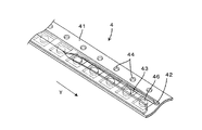
- FIG. 2 is a perspective view showing the structure of the tape.
- the tape 4 is composed of a carrier tape 41 made of synthetic resin or paper, and a thin sheet-shaped cover tape 42 made of synthetic resin attached to the carrier tape 41.
- the carrier tape 41 has a plurality of concave component accommodating portions 43 opened upward at regular intervals, and each component accommodating portion 43 accommodates the component 46.
- the cover tape 42 is fixed to the carrier tape 41 by attaching the left and right side edges in the width direction of the cover tape 42 to the upper surface of the carrier tape 41 in the left and right side edges, and the component 46 accommodates the component. It prevents it from falling out of the part 43. Further, on one side edge of the carrier tape 41, a plurality of feed holes 44 are provided at regular intervals along the extending direction of the carrier tape 41.
- the cover tape 42 of the tape 4 is cut by the insertion blade (reference numeral 533 in FIG. 6) before being delivered in the delivery direction Y in the feeder 5 and supplied to the component supply position P1. .. More specifically, as shown in FIG. 2, a substantially central portion of the cover tape 42 in the left-right direction is cut along the delivery direction of the tape 4. As a result, the component 46 accommodated in the component accommodating portion 43 is exposed, and the component can be adsorbed by the suction nozzle at the component supply position P1 as described below.
- the component 46 supplied to the component supply position P1 is mounted on the substrate S by the head unit 3.
- the head unit 3 has a plurality (4) mounting heads 31 arranged in the X direction.
- Each mounting head 31 has a long shape extending in the Z direction (vertical direction), and parts are sucked and held by suction nozzles (reference numerals 311 in FIGS. 6 and 7) detachably attached to the lower ends thereof. can do. That is, the mounting head 31 moves above the feeder 5 and sucks the component 46 supplied to the component supply position P1 by the feeder 5. Subsequently, the mounting head 31 moves above the substrate S at the working position to release the suction of the component 46, thereby mounting the component 46 on the substrate S.
- FIG. 3 is a perspective view of a feeder according to a first embodiment of the parts supply device according to the present invention.
- FIG. 4 is a diagram showing the structure of the feeder tip portion in a state where the guide member is removed.
- the feeder 5 is a feeder having an auto-loading mechanism that automatically loads the tape 4 inserted from the insertion port on the upstream side to the component supply position P1, and is configured as follows.
- the downstream side (the side facing the conveyor 12 and the lower right side in FIG. 3) in the sending direction Y in which the parts 46 are sent toward the parts supply position is the front side.
- the upstream side in the delivery direction Y (the side away from the conveyor 12 and the upper left side in FIG. 3) is the rear side.
- the direction orthogonal to both the front-rear direction (Y direction) and the vertical direction (Z direction) of the feeder 5 is defined as the width direction (X direction) of the feeder 5.
- the front-rear direction (Y direction) and the width direction (X direction) of the feeder 5 are also the transmission direction and the width direction of the tape 4, respectively.
- a plurality of feeders 5 can be attached to the dolly 6 in a line in the X direction. As shown in FIG. 3, each feeder 5 has a long shape in the front-rear direction (Y direction) with respect to the main body 51 in order to send the tape 4 holding the component 46 toward the component supply position P1.
- a front delivery unit 52 and a rear transmission unit 54 are provided.
- the front sending portion 52 is provided in the front portion of the main body 51.
- the front delivery unit 52 transmits the front sprocket 521, the front motor (not shown) which is the drive source of the front sprocket 521, and the rotational driving force generated by the front motor to the front sprocket 521. It has a gear group 522.
- the front motor is driven and controlled in response to an operation command from a control unit (not shown) that controls the entire device.
- the power of the front motor is transmitted to the front sprocket 521 via the front gear group 522, and rotates the front sprocket 521 at the component supply position P1.
- a part of the front gear group 522 functions as the "power transmission member" of the present invention, and is arranged below the groove portion 511 of the main body portion 51 at the component supply position P1. ..
- the groove portion 511 extends in the delivery direction Y while opening toward the lower surface of the tape 4 fed by the front delivery portion 52 on the upper surface portion of the main body portion 51.
- a concave space is provided so that a leaf spring member described in detail later can be fitted from the opening, and the inner bottom surface 511a of the groove portion 511 faces the lower surface of the tape 4, and the "opposing surface” of the present invention. It corresponds to one example.
- a protruding region 514 that protrudes upward is provided in a portion of the inner bottom surface 511a that corresponds to the component supply position P1. Therefore, at the component supply position P1, the distance between the inner bottom surface 511a of the groove portion 511 and the leaf spring member 55 is narrow, and the space is narrow.
- an intermediate sprocket is arranged in the front delivery portion 52 on the upstream side of the front sprocket 521 in the delivery direction Y of the tape 4, via the front gear group 522. It rotates by receiving the rotational driving force. Similar to the front sprocket 521, teeth engaged with the feed holes 44 of the tape 4 are formed on the outer circumference of the intermediate sprocket at equal pitches. Therefore, the front sending portion 52 rotates the front sprocket 521 and the intermediate sprocket with each tooth engaged with the feeding hole 44 of the tape 4, so that the tape 4 sent from the rear sending portion 54 side is brought into the main body. It is delivered to the component supply position P1 along the groove portion 511 provided on the front upper surface of the 51.
- the rear delivery unit 54 is basically configured in the same manner as the front transmission unit 52, except that there is only one sprocket.
- a guide member 53 is provided to guide the tape 4 delivered to the component supply position P1 in this way.
- the guide member 53 is an elongated member extending in the Y direction (front-rear direction), and is removable from the main body 51 so as to cover the groove 511 from above. That is, the tape 4 can be sent out by attaching the guide member 53 to the main body 51 after arranging the tape 4 along the groove 511. Then, when the tape 4 is sent out, the guide member 53 guides the running of the tape 4 sent out along the groove portion 511 by the front side sending portion 52.
- the upper surface of the guide member 53 has an opening 531 for taking out parts corresponding to the part supply position P1 and an opening 532 provided so as to face the exposure mechanism. It is provided.
- the opening 531 is located at the component supply position P1, and the component 46 can be taken out by the suction nozzle (reference numeral 311 in FIGS. 6 and 7).
- the insertion blade 533 for cutting the cover tape is located below the opening 532. The insertion blade 533 is attached to the inside of the guide member 53 so as to face the cover tape 42, and its tip is located at the tape cutting position P2.
- a spring (not shown) is connected to the guide member 53 configured in this way, and while pressing the tape 4 delivered in the delivery direction Y from above, it moves in the vertical direction Z according to the thickness of the tape 4.
- a leaf spring member 55 is arranged between the lower surface of the tape 4 and the inner bottom surface 511a of the groove portion 511, and supports the tape 4 while urging it upward.
- the feeder 5 has a wire spring member 56 that urges the leaf spring member 55 upward near the component supply position P1 and a leaf spring member 55 upward near the tape cutting position P2. It has a pusher portion 57 that pushes up.
- FIG. 5 is a diagram schematically showing a state in which the wire spring member is attached to the groove.
- FIG. 6 is a partial cross-sectional view taken along the delivery direction of the feeder shown in FIG.
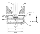
- FIG. 7 is a partial cross-sectional view taken along the width direction of the feeder at the component supply position.
- the leaf spring member 55 extends in the delivery direction Y. As shown in FIG. 7, the leaf spring member 55 has a width size D5 slightly narrower than the size of the groove portion 511 (width size D511) in the width direction X, and can be fitted into the concave space of the groove portion 511.
- both end portions thereof come into contact with the inner bottom surface 511a of the groove portion 511.
- the rear end is fixed by a screw (not shown) at the leaf spring contact position (reference numeral P3 in FIG. 3), while the front end is grooved at the leaf spring contact position (reference P4 in FIG. 3). It is slidable on the inner bottom surface 511a of 511. Further, the central portion of the leaf spring member 55 protrudes upward (+ Z) and comes into contact with the lower surface of the tape 4 as shown in FIG. 6, more specifically, the bottom portion of the component accommodating portion 43.
- the leaf spring member 55 supports the tape 4 while urging upward while resisting the tape 4 pushed downward by the guide member 53.
- the width size D5 of the leaf spring member 55 in the width direction X is narrower than the width size of the carrier tape 41, and the width size D4 of the component accommodating portion 43. Is wider than. The same applies to the magnet 58 described below.
- the magnet 58 is attached to the lower surface of the leaf spring member 55 at the component supply position P1 and before and after it.
- the magnetic force from the magnet 58 stabilizes the posture of the component 46 located at the component supply position P1, and the suction nozzle 311 can satisfactorily attract the component 46.
- a magnet 59 is attached to the lower surface of the leaf spring member 55 at the tape cutting position P2 and before and after the tape cutting position P2, and the tape is stably cut by the insertion blade 533.
- the leaf spring member 55 supports the tape 4 while urging it upward, but it is difficult for the leaf spring member 55 alone to elastically support the tape 4. Therefore, in the present invention, the leaf spring member 55 is urged upward by adding an urging member such as a spring or an elastic member such as rubber or resin below the component supply position P1 and the magnet 58 located before and after the component supply position P1. There is. As a result, it is possible to stably supply the parts 46 housed in the tape 4 by giving a sufficient urging force to the tape 4 sent to the parts supply position P1.
- an urging member such as a spring or an elastic member such as rubber or resin
- the wire spring member 56 is used as the "urging member" of the present invention in order to cope with such spatial restrictions.
- the wire spring member 56 is a spring steel wire having a round cross-sectional shape with a diameter of D6 ( ⁇ D4 ⁇ D5 ⁇ D511), and has a shape corresponding to the shape of a narrow space sandwiched between the magnet 58 and the inner bottom surface 511a of the groove portion 511. It is a finished product. That is, the wire spring member 56 is between the leaf spring member 55 and the inner bottom surface 511a of the groove portion 511 in the vertical direction Z, and between the pair of leaf spring contact positions P3 and P4 (see FIG. 3) in the delivery direction Y. Is extended in the sending direction Y. Both ends of the wire spring member 56 come into contact with the inner bottom surface 511a of the groove portion 511. As shown in FIGS.
- the front end portion is inserted into a recess 512 provided downward from the inner bottom surface 511a of the groove portion 511 in a state of being bent at an obtuse angle.
- the front end portion of the wire spring member 56 is locked and fixed to the main body portion 51.
- the rear end portion is slidable on the inner bottom surface 511a of the groove portion 511, and as described below, the rear end portion is slidable on the inner bottom surface 511a of the groove portion 511 according to the pressing amount of the central portion of the wire spring member 56. It slides in the delivery direction Y.
- the relationship between both ends of the wire spring member 56 may be interchanged. That is, it is possible to fix the rear end portion of the wire spring member 56 and slidably configure the front end portion.
- the component supply position P1 or the component supply position P1 in the delivery direction Y it is desirable to set it at a position adjacent to. However, considering the following points, it is optimal to position the urging position P5 on the upstream side of the component supply position P1 in the delivery direction Y, as shown in FIG. That is, the opening 531 of the guide member 53 exists at the component supply position P1, and the tape 4 is positioned with the component 46 exposed upward.
- the urging position P5 coincides with the component supply position P1
- the tape 4 becomes press-free on the opposite side (upper side) of the urging position P5 sandwiching the tape 4.
- the urging force is applied while the tape 4 is pressed by the guide member 53.
- the parts 46 can be supplied while stabilizing the posture of the tape 4 before being supplied to the parts supply position P1, which is more preferable.
- the central portion of the wire spring member 56 is pressed downward by the pusher portion 57 in a no-load state to generate a constant elastic force in the wire spring member 56.
- the "no load state” means a state before the tape 4 is set on the feeder 5, that is, a state in which the guide member 53 is removed from the main body 51 and no load is applied to the leaf spring member 55. doing.
- pressing the central portion of the wire spring member 56 downward by the pusher portion 57 to generate a constant elastic force in the wire spring member 56 is referred to as "preload” in the present specification. The following effects can be obtained by this preload.
- the pusher unit 57 that executes such a preload functions as the "preload unit” of the present invention, but in the present embodiment, it also functions as the "tape cut stabilizing unit” and the “runout control unit” of the present invention.
- the configuration and operation of the pusher portion 57 will be described with reference to FIGS. 4 to 6.
- the pusher portion 57 is provided near the upstream side of the insertion blade 533 in the delivery direction Y.
- the pusher portion 57 has a movable member 571 that can move in the Z direction, a coil spring 572 that urges the movable member 571 upward, and a stopper 573.
- the movable member 571 includes a bottle cap-shaped base portion 571a, a push portion 571b projecting upward from the base portion 571a, and an insertion portion projecting downward from the base portion 571a and inserted into the hollow portion of the coil spring 527. It has 571c.
- the outer diameter of the base portion 571a is slightly narrower than the inner diameter of the recess 513 provided below the inner bottom surface 511a of the groove portion 511, and the inner diameter of the base portion 571a is narrower than the outer diameter of the coil spring 572. Therefore, when the coil spring 57 2 is inserted into the recess 513 and the base portion 571a is inserted into the recess 513 while the insertion portion 571c is further inserted into the hollow portion of the coil spring 572, the upper end portion of the coil spring 572 is capped by the base portion 571a.
- the push portion 571b has a cylindrical shape thinner than the base portion 571a, and a step portion is formed between the base portion 571a and the push portion 571b.
- the stopper 573 is fixed to the inner bottom surface 511a of the groove portion 511 by pushing the step portion into the recess 513. Therefore, as shown in FIGS. 4 and 5, in the no-load state, the step portion is locked by the stopper 573 and the push portion 571b is raised to the maximum.
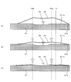
- FIG. 6 when the tape 4 is set on the feeder 5 and a load is applied to the leaf spring member 55, the leaf spring member 55 and the magnet 59 move downward in the vicinity of the tape cutting position P2.
- the movable member 571 is pushed downward while resisting the urging force of the coil spring 572.
- An elastic force corresponding to the pushing amount at this time is generated in the coil spring 572, and is given as an urging force toward the leaf spring member 55 via the magnet 59.
- the pusher portion 57 By the push-up by the pusher portion 57, the posture of the tape 4 is fixed in the vicinity of the tape cutting position P2, and the tape cutting by the insertion blade 533 is performed more stably. In this way, the pusher portion 57 also functions as a “tape cut stabilizing portion”.
- the push portion 571b of the pusher portion 57 is provided with a guide hole 571d penetrating in parallel with the delivery direction Y, and a wire spring member 56 is provided in the guide hole 571d. It has been inserted.
- the guide hole 571d has an elongated hole shape in the vertical direction Z, and allows the wire spring member 56 to move in the vertical direction Z. Therefore, in the no-load state, the wire spring member 56 is locked on the upper inner peripheral surface of the guide hole 571d as shown in FIGS. 4 and 5, and the preload is stably executed. Further, as shown in FIG.
- the wire spring member 56 and the movable member 571 of the pusher portion 57 move in the vertical direction Z. , Vertical movement and interference of the wire spring member 56 are surely avoided.
- the movement of the wire spring member 56 in the width direction X is restricted by the inner surface of the guide hole 571d. Therefore, it is possible to stably continue applying the urging force by the wire spring member 56. In this way, the pusher portion 57 also functions as the “shake control portion” of the present invention.
- the wire spring member 56 urges the leaf spring member 55 via the magnet 58, which is sufficient for the tape 4 sent to the component supply position P1. It can give urging power. As a result, the component 46 housed in the tape 4 can be stably supplied, and the operating rate of the component mounting device 1 can be increased.
- the inner bottom surface 511a of the groove portion 511 has a protruding region 514 protruding upward at the component supply position P1. Therefore, in the vertical direction Z, the distance between the inner bottom surface 511a of the groove portion 511 and the leaf spring member 55 is narrow, and the space is narrow.
- the wire spring member 56 is arranged so that the central portion of the wire spring member 56 protrudes along the protruding region 514.
- the wire spring member 56 has a technical feature that the deformation in the height direction (vertical direction Z) when urging the leaf spring member 55 is smaller than that of other urging members such as coil springs. Therefore, even under such a narrow space condition, the wire spring member 56 can effectively apply the urging force to the leaf spring member 55.
- the pusher portion 57 having a function as a "preload portion” and a “runout control portion” is provided, it is possible to further stabilize the application of the urging force by the wire spring member 56, and the reliability of parts supply can be improved. Can be enhanced.
- a configuration other than the pusher portion 57 for example, a wire spring locking portion adopted in the second embodiment described later may be provided as the "preload portion" of the present invention, a “runout control portion” may be separately provided, or a “preload” may be provided.
- a configuration having both a “unit” and a “swing control unit” may be added.
- the pusher portion 57 also functions as a "preload portion” and a "runout control portion", the number of parts of the feeder 5 can be suppressed.
- the present invention is not limited to the above-described embodiment, and various modifications can be made to the above-described one without departing from the spirit of the present invention. Therefore, for example, in the above embodiment, the wire spring member 56 is urged toward the leaf spring member 55 at one location in the central portion, that is, the urging position P5 is at one location.
- the number of urging positions P5 is not limited to this, and two urging positions P5a and P5b may be provided at a plurality of locations, for example, as shown in FIG. 8 (second embodiment).
- the wire spring locking portion 60 is erected from the inner bottom surface 511a of the groove portion 511 between the urging positions P5a and P5b, and the wire spring member 56 is locked by the wire spring locking portion 60 in a no-load state. It may be preloaded.
- a member having the same shape as the push portion 571b is erected from the inner bottom surface 511a of the groove portion 511, and the wire spring member 56 is inserted into the guide hole to regulate preload and runout. May be configured to achieve at the same time.
- the cross section of the wire spring member 56 is round, but other than this, it may be elliptical or polygonal.
- the number of the wire spring members 56 is not limited to one, and may be a plurality of wire spring members 56.
- the width size D6 of the wire spring member 56 in the width direction X is suppressed to 50% or less of the width size D5 (FIG. 7) of the leaf spring member 55. ..
- the present invention is applied to the feeder 5 of the type in which the cover tape 42 is cut by the insertion blade 533, but the carriers on both sides of the cover tape 42 in the width direction X are used.
- the present invention can be applied to both a feeder that peels off both of the adhesive portions to the tape 41 and a type that peels off only one side by autoloading.
- the present invention can also be applied to feeders other than feeders having an auto-loading function.
- the present invention can be applied to all parts supply devices for supplying parts by sending a tape for storing parts to a parts supply position and all parts mounting devices equipped with the parts supply device.
- Inner bottom surface (opposing surface) of the groove 514 ... Projection area (on the inner bottom surface) P1 ... Parts supply position P5, P5a, P5b ... Biasing position S ... Board X ... Width direction Y ... Delivery direction
Landscapes
- Engineering & Computer Science (AREA)
- Manufacturing & Machinery (AREA)
- Microelectronics & Electronic Packaging (AREA)
- Supply And Installment Of Electrical Components (AREA)
Abstract
Description
3…ヘッドユニット
4…テープ
5…テープフィーダー(部品供給装置)
6…括交換台車,台車
11…基台
12…コンベア
21…Y軸レール
22…Y軸ボールネジ
23…ヘッド支持部材
24…X軸ボールネジ
31…実装ヘッド
41…キャリアテープ
42…カバーテープ
43…部品収容部
44…送り孔
46…部品
51…本体部
52…前側送出部
55…板バネ部材
56…線バネ部材
57…プッシャ部(プリロード部、振れ規制部)
60…線バネ係止部(プリロード部)
511…溝部
511a…溝部の内底面(対向面)
514…(内底面の)突出領域
P1…部品供給位置
P5,P5a,P5b…付勢位置
S…基板
X…幅方向
Y…送出方向
Claims (10)
- 部品を収納するテープを送出方向に送って前記部品を部品供給位置に供給する送出部と、
前記送出部により送られる前記テープの下面に対向しながら前記送出方向に延設される対向面を有する本体部と、
前記送出方向に延設され、両端部が前記対向面に当接するとともに中央部が上方に湾出して前記部品供給位置で前記テープの下面を上方に付勢しながら支持する板バネ部材と、
前記板バネ部材と前記対向面との間に配置されて前記板バネ部材を上方に付勢する付勢部材と、
を備えることを特徴とする部品供給装置。 - 請求項1に記載の部品供給装置であって、
前記付勢部材は、多角形状、丸形状または楕円形状の断面を有し、前記板バネ部材の両端部が前記対向面に当接する一対の板バネ当接位置の間で前記送出方向に延設される線バネ部材であり、
前記線バネ部材の両端部が前記対向面に当接するとともに中央部が上方に湾出して前記板バネ部材の前記中央部を上方に付勢する部品供給装置。 - 請求項2に記載の部品供給装置であって、
前記線バネ部材が前記板バネ部材に向けて付勢する付勢位置が前記送出方向において前記部品供給位置の上流側に隣接する位置であり、
前記送出方向における前記線バネ部材の一方端部が前記対向面に固定され、他方端部が前記線バネ部材の前記中央部の押下量に応じて前記対向面上を前記送出方向に摺動する部品供給装置。 - 請求項2または3に記載の部品供給装置であって、
前記板バネ部材に対して上方から荷重が印加されていない無荷重状態において前記線バネ部材の前記中央部を下方に押え込んで一定の弾発力を発生させるとともに、前記板バネ部材に対して上方から前記弾発力以上の荷重が印加される荷重状態において前記線バネ部材の前記中央部の押え込みが解除されるように構成されたプリロード部を備える部品供給装置。 - 請求項2ないし4のいずれか一項に記載の部品供給装置であって、
前記板バネ部材と前記対向面との間において、前記テープの幅方向の両側から前記線バネ部材の前記幅方向の振れを規制する振れ規制部を備える部品供給装置。 - 請求項2ないし5のいずれか一項に記載の部品供給装置であって、
前記送出部は、前記部品供給位置で前記テープに設けられる送り孔と係合しながら回転自在に設けられたスプロケットと、前記対向面の下方に配置されて前記スプロケットに回転駆動力を伝達して前記スプロケットを回転させる動力伝達部材とを有し、
前記対向面は前記動力伝達部材に対応して前記部品供給位置または近傍で上方に突出した突出領域を有するとともに、前記突出領域に沿って前記線バネ部材の前記中央部が配置されている部品供給装置。 - 請求項2に記載の部品供給装置であって、
前記線バネ部材が前記板バネ部材に向けて付勢する付勢位置は前記送出方向において前記部品供給位置または前記部品供給位置に隣接する位置である部品供給装置。 - 請求項7に記載の部品供給装置であって、
前記付勢位置は前記送出方向において前記部品供給位置の上流側に隣接する位置である部品供給装置。 - 請求項1ないし8のいずれか一項に記載の部品供給装置であって、
前記本体部は、前記テープの下面に向けて開口しながら前記送出方向に延設され、前記開口から前記板バネ部材を嵌入可能に凹状空間が設けられる溝部を有し、
前記溝部の内底面は前記対向面である部品供給装置。 - 請求項1ないし9のいずれか一項に記載の部品供給装置と、
前記部品供給装置により供給される前記部品を基板上に装着するヘッドユニットと
を備えることを特徴とする部品実装装置。
Priority Applications (5)
| Application Number | Priority Date | Filing Date | Title |
|---|---|---|---|
| CN202080078017.2A CN114667810B (zh) | 2020-03-17 | 2020-03-17 | 部件供给装置及部件安装装置 |
| JP2022508644A JP7268244B2 (ja) | 2020-03-17 | 2020-03-17 | 部品供給装置および部品実装装置 |
| DE112020006274.0T DE112020006274T5 (de) | 2020-03-17 | 2020-03-17 | Bauteilzufuhrvorrichtung und Bauteilmontagevorrichtung |
| US17/786,456 US12336107B2 (en) | 2020-03-17 | 2020-03-17 | Component supply apparatus and component mounting apparatus |
| PCT/JP2020/011650 WO2021186533A1 (ja) | 2020-03-17 | 2020-03-17 | 部品供給装置および部品実装装置 |
Applications Claiming Priority (1)
| Application Number | Priority Date | Filing Date | Title |
|---|---|---|---|
| PCT/JP2020/011650 WO2021186533A1 (ja) | 2020-03-17 | 2020-03-17 | 部品供給装置および部品実装装置 |
Publications (1)
| Publication Number | Publication Date |
|---|---|
| WO2021186533A1 true WO2021186533A1 (ja) | 2021-09-23 |
Family
ID=77770915
Family Applications (1)
| Application Number | Title | Priority Date | Filing Date |
|---|---|---|---|
| PCT/JP2020/011650 Ceased WO2021186533A1 (ja) | 2020-03-17 | 2020-03-17 | 部品供給装置および部品実装装置 |
Country Status (5)
| Country | Link |
|---|---|
| US (1) | US12336107B2 (ja) |
| JP (1) | JP7268244B2 (ja) |
| CN (1) | CN114667810B (ja) |
| DE (1) | DE112020006274T5 (ja) |
| WO (1) | WO2021186533A1 (ja) |
Families Citing this family (1)
| Publication number | Priority date | Publication date | Assignee | Title |
|---|---|---|---|---|
| EP3820264A1 (en) * | 2019-11-11 | 2021-05-12 | Mycronic AB | A tape guide for guiding a component tape |
Citations (4)
| Publication number | Priority date | Publication date | Assignee | Title |
|---|---|---|---|---|
| JP2010245385A (ja) * | 2009-04-08 | 2010-10-28 | Hitachi High-Tech Instruments Co Ltd | 電子部品装着装置及び部品供給装置 |
| JP2011216793A (ja) * | 2010-04-01 | 2011-10-27 | Hitachi High-Tech Instruments Co Ltd | 電子部品供給装置 |
| JP2014011326A (ja) * | 2012-06-29 | 2014-01-20 | Hitachi High-Tech Instruments Co Ltd | 部品供給ユニット |
| WO2020012875A1 (ja) * | 2018-07-10 | 2020-01-16 | パナソニックIpマネジメント株式会社 | 部品供給装置 |
Family Cites Families (8)
| Publication number | Priority date | Publication date | Assignee | Title |
|---|---|---|---|---|
| JP5909689B2 (ja) * | 2013-02-08 | 2016-04-27 | パナソニックIpマネジメント株式会社 | 部品供給装置および部品供給方法 |
| JP6681344B2 (ja) * | 2015-01-22 | 2020-04-15 | 株式会社Fuji | フィーダ装置 |
| JP6779826B2 (ja) * | 2017-04-12 | 2020-11-04 | ヤマハ発動機株式会社 | 部品供給装置、部品実装機 |
| JP6806622B2 (ja) * | 2017-04-28 | 2021-01-06 | ヤマハ発動機株式会社 | 部品供給装置、表面実装機 |
| CN111247882B (zh) * | 2017-10-31 | 2021-06-22 | 雅马哈发动机株式会社 | 元件供给装置及元件安装装置 |
| US11291148B2 (en) * | 2017-10-31 | 2022-03-29 | Yamaha Hatsudoki Kabushiki Kaisha | Component supply device and component mounting device |
| CN111418275B (zh) * | 2017-12-26 | 2021-03-23 | 株式会社富士 | 供料器 |
| JP7142268B2 (ja) * | 2018-10-15 | 2022-09-27 | パナソニックIpマネジメント株式会社 | 部品供給装置および部品供給方法 |
-
2020
- 2020-03-17 CN CN202080078017.2A patent/CN114667810B/zh active Active
- 2020-03-17 JP JP2022508644A patent/JP7268244B2/ja active Active
- 2020-03-17 US US17/786,456 patent/US12336107B2/en active Active
- 2020-03-17 DE DE112020006274.0T patent/DE112020006274T5/de active Pending
- 2020-03-17 WO PCT/JP2020/011650 patent/WO2021186533A1/ja not_active Ceased
Patent Citations (4)
| Publication number | Priority date | Publication date | Assignee | Title |
|---|---|---|---|---|
| JP2010245385A (ja) * | 2009-04-08 | 2010-10-28 | Hitachi High-Tech Instruments Co Ltd | 電子部品装着装置及び部品供給装置 |
| JP2011216793A (ja) * | 2010-04-01 | 2011-10-27 | Hitachi High-Tech Instruments Co Ltd | 電子部品供給装置 |
| JP2014011326A (ja) * | 2012-06-29 | 2014-01-20 | Hitachi High-Tech Instruments Co Ltd | 部品供給ユニット |
| WO2020012875A1 (ja) * | 2018-07-10 | 2020-01-16 | パナソニックIpマネジメント株式会社 | 部品供給装置 |
Also Published As
| Publication number | Publication date |
|---|---|
| JP7268244B2 (ja) | 2023-05-02 |
| JPWO2021186533A1 (ja) | 2021-09-23 |
| US20230023441A1 (en) | 2023-01-26 |
| US12336107B2 (en) | 2025-06-17 |
| DE112020006274T5 (de) | 2022-11-17 |
| CN114667810B (zh) | 2024-07-16 |
| CN114667810A (zh) | 2022-06-24 |
Similar Documents
| Publication | Publication Date | Title |
|---|---|---|
| JP6431048B2 (ja) | フィーダ | |
| JP6707626B2 (ja) | 部品供給装置 | |
| JP2019149425A (ja) | 電子部品供給装置及び電子部品実装装置 | |
| WO2021186533A1 (ja) | 部品供給装置および部品実装装置 | |
| JP4804296B2 (ja) | 部品供給装置及び表面実装機 | |
| WO2015189986A1 (ja) | 部品装着機 | |
| JP2014216468A (ja) | バックアップピン、基板支持装置、基板処理装置 | |
| JP2017028041A (ja) | テープフィーダ | |
| JP2013065748A (ja) | 電子部品実装装置およびテープフィーダならびにテープフィーダにおけるトップテープ送り方法 | |
| KR20110070803A (ko) | 전자부품피더 | |
| JP2004228248A (ja) | テープ式電子部品供給装置 | |
| JP5850780B2 (ja) | 部品供給装置及びその調整方法 | |
| JP6801099B2 (ja) | 電子部品装着機 | |
| JP2009239108A (ja) | 部品供給装置の取付構造および表面実装機 | |
| JP2007150105A (ja) | 電子部品装着装置 | |
| JP3620931B2 (ja) | テープ送出装置 | |
| JP3453447B2 (ja) | 実装機のノズル保持構造 | |
| JP4095917B2 (ja) | トレー式部品供給装置及びそのパレット位置決め方法 | |
| JP2014022635A (ja) | テープフィーダ及び電子部品装着装置 | |
| JP2003092492A (ja) | 部品供給装置および部品供給方法 | |
| JP7123145B2 (ja) | テープフィーダ | |
| JP4387816B2 (ja) | 電子部品装着装置 | |
| JP6898782B2 (ja) | リール保持装置 | |
| JP2009130322A (ja) | テープフィーダーおよび表面実装機 | |
| JP6689653B2 (ja) | 部品実装装置および部品実装装置用ヘッドユニット |
Legal Events
| Date | Code | Title | Description |
|---|---|---|---|
| 121 | Ep: the epo has been informed by wipo that ep was designated in this application |
Ref document number: 20925462 Country of ref document: EP Kind code of ref document: A1 |
|
| ENP | Entry into the national phase |
Ref document number: 2022508644 Country of ref document: JP Kind code of ref document: A |
|
| 122 | Ep: pct application non-entry in european phase |
Ref document number: 20925462 Country of ref document: EP Kind code of ref document: A1 |
|
| WWG | Wipo information: grant in national office |
Ref document number: 17786456 Country of ref document: US |