WO2021171503A1 - 天井埋込型空気調和機 - Google Patents
天井埋込型空気調和機 Download PDFInfo
- Publication number
- WO2021171503A1 WO2021171503A1 PCT/JP2020/008105 JP2020008105W WO2021171503A1 WO 2021171503 A1 WO2021171503 A1 WO 2021171503A1 JP 2020008105 W JP2020008105 W JP 2020008105W WO 2021171503 A1 WO2021171503 A1 WO 2021171503A1
- Authority
- WO
- WIPO (PCT)
- Prior art keywords
- grill
- suction grill
- decorative panel
- suction
- indoor unit
- Prior art date
- Legal status (The legal status is an assumption and is not a legal conclusion. Google has not performed a legal analysis and makes no representation as to the accuracy of the status listed.)
- Ceased
Links
Images


Classifications
-
- F—MECHANICAL ENGINEERING; LIGHTING; HEATING; WEAPONS; BLASTING
- F24—HEATING; RANGES; VENTILATING
- F24F—AIR-CONDITIONING; AIR-HUMIDIFICATION; VENTILATION; USE OF AIR CURRENTS FOR SCREENING
- F24F1/00—Room units for air-conditioning, e.g. separate or self-contained units or units receiving primary air from a central station
- F24F1/0007—Indoor units, e.g. fan coil units
- F24F1/0043—Indoor units, e.g. fan coil units characterised by mounting arrangements
- F24F1/0047—Indoor units, e.g. fan coil units characterised by mounting arrangements mounted in the ceiling or at the ceiling
-
- F—MECHANICAL ENGINEERING; LIGHTING; HEATING; WEAPONS; BLASTING
- F24—HEATING; RANGES; VENTILATING
- F24F—AIR-CONDITIONING; AIR-HUMIDIFICATION; VENTILATION; USE OF AIR CURRENTS FOR SCREENING
- F24F13/00—Details common to, or for air-conditioning, air-humidification, ventilation or use of air currents for screening
- F24F13/08—Air-flow control members, e.g. louvres, grilles, flaps or guide plates
- F24F13/082—Grilles, registers or guards
- F24F13/085—Grilles, registers or guards including an air filter
-
- F—MECHANICAL ENGINEERING; LIGHTING; HEATING; WEAPONS; BLASTING
- F24—HEATING; RANGES; VENTILATING
- F24F—AIR-CONDITIONING; AIR-HUMIDIFICATION; VENTILATION; USE OF AIR CURRENTS FOR SCREENING
- F24F13/00—Details common to, or for air-conditioning, air-humidification, ventilation or use of air currents for screening
- F24F13/20—Casings or covers
Definitions
- the present invention relates to an air conditioner, and more particularly to a ceiling-embedded air conditioner having a decorative panel mounted on the lower part of the ceiling-embedded air conditioner.
- the decorative panel of the ceiling-embedded air conditioner is preferably a structure in which the suction grill is expanded to the vicinity of the air outlet provided on the outer periphery of the decorative panel.
- FIG. 8 shows a schematic structure of an indoor unit 800 of a conventional ceiling-embedded air conditioner.
- the decorative panel 801 installed adjacent to the ceiling (not shown) is arranged on the indoor side.
- An air outlet 802 is formed inside the decorative panel 801, and an air direction plate 806 is arranged inside the air outlet 802 via an appropriate pivot mechanism 807 and a drive mechanism.
- a heat exchanger 810 and a drain pan 811 are arranged in the main body 809 of the indoor unit 800.
- the heat exchanger 810 exchanges heat between the heat exchange medium sent from the outdoor unit (not shown) and the indoor air.
- the conditioned air after heat exchange is ejected from the outlet 802 into the room to harmonize the air in the room.
- the drain pan 811 is arranged below the heat exchanger 810 in order to receive the drain water from the heat exchanger 810.
- Insulation material 805 for preventing dew condensation is arranged on both sides of the air outlet 802, and the suction grill 803 extends close to the inner heat insulating material 805.
- the suction grill 803 is provided with an opening for introducing indoor air into the indoor unit 800, and a filter (not shown) is placed on the indoor unit 800 side of the suction grill 803.
- the suction grill 803 needs to be opened and closed for cleaning or replacement of the filter or maintenance of the indoor unit 800.
- the hinge 808 that engages with the decorative panel 801 at the end of the suction grill 803. Is placed.
- a knob arranged near the right-hand side end of the paper surface of the suction grill 803 is operated to release the connection with the decorative panel 801.
- the suction grill 803 When the suction grill 803 is expanded to the vicinity of the air outlet 802 under the configuration of FIG. 8, it becomes difficult to secure a space for providing the hinge 808 which is the axis of opening and closing due to the volume of the heat insulating material 805. Therefore, there has been a problem that the suction grill 803 cannot be opened and closed by using a simple structure. From this point of view, the region 804 formed between the outlet 802 and the suction grill 803 can be said to be a region that deteriorates the design of the decorative panel 801 from the viewpoint of the interior design, and the hinge structure is improved. There is still room for effective use.
- the suction grill 803 when the suction grill 803 is expanded to the vicinity of the outlet 802, the suction grill 803 becomes larger than the conventional suction grill, and as a result, the weight of the suction grill 803 increases, and the same configuration is applied to the decorative panel with the elevating grill. When adopted, there was a concern that the output of the suction grill elevating motor would be insufficient.
- WO2018 / 179136 Patent Document 1
- the international publication WO2018 / 179136 has the purpose of improving the workability inside the indoor unit. It is equipped with a suction grill provided on the design side of the decorative panel and side panels provided on the left and right sides of the suction grill. Describes a ceiling-embedded air conditioner in which the freely attached side panel can be removed.
- the indoor unit described in Patent Document 1 can improve the accessibility to the inside of the indoor unit, but adds a side panel which is not related to the design, and rather lowers the design of the indoor unit. It ends up. Further, the purpose is not to improve the design by extending the suction grill to the vicinity of the air outlet.
- Patent Document 2 describes a composite air conditioner in which a side grill is provided at one end of a front grill.
- Patent Document 2 does not aim to improve the design of the indoor unit of the ceiling-embedded air conditioner.
- the present invention has been made in view of the above problems, and the present invention makes it easy to open and close the suction grill while making the suction grill look wider, and despite the increase in the area of the suction grill, the weight of the suction grill is reduced. It is an object of the present invention to provide a ceiling-embedded air conditioner having a structure.
- a ceiling-embedded air conditioner equipped with an indoor unit including a fan, a fan motor, and a heat exchanger.
- the indoor unit is A decorative panel that is installed toward an air-conditioned space and has a suction port and an outlet. Including the grill attached to the decorative panel The grill has a suction grill provided at the suction port and a dummy grill extending from at least one end of the suction grill and provided between the suction port and the air outlet.
- a ceiling-embedded air conditioner is provided.
- FIG. 1 is a schematic cross-sectional view of the indoor unit 100 of the exemplary embodiment.
- FIG. 2 is a diagram showing an exemplary embodiment 200 in which the suction grill 109b of the indoor unit 100 is opened in the exemplary embodiment.
- FIG. 3 is a diagram showing a suction grill structure 300 when the indoor unit 100 of the exemplary embodiment is viewed from the indoor side.
- FIG. 4 is an enlarged view showing the inner structure 400 of the decorative panel 107 in the direction along the arrow line CC of FIG.
- FIG. 5 is a schematic view of the inner structure 500 when the suction grill 109b is opened for maintenance or the like.
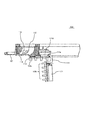
- FIG. 6 is an enlarged view of the internal structure 600 in which the end portion corresponding to the decorative panel 107 shown in FIGS. 4 and 5 is enlarged in the direction of the cutting line DD of FIG.
- FIG. 7 is a diagram showing an exemplary modification.
- FIG. 8 is a diagram showing an edge structure of an indoor unit 800 of a conventional ceiling-embedded
- FIG. 1 shows a schematic cross-sectional view of the indoor unit 100 of the exemplary embodiment.
- the indoor unit 100 shown in FIG. 1 is an indoor unit 100 of a ceiling-embedded air conditioner, and drives a heat exchanger 103, a fan 105, and a fan 105 in a housing 102 of the indoor unit 100. Accommodates the fan motor 106 for the purpose.
- the indoor air is sucked in the direction of the arrow A, directed to the heat exchanger 103 according to the airflow generated by the fan 105, and exchanges heat with the heat exchange medium circulating in the heat exchanger 103.
- the conditioned air after heat exchange is discharged from the outlet 108 in the direction of arrow B toward the room, which is an exemplary air conditioned space.
- a drain pan 104 is arranged below the heat exchanger 103 to collect drain water, dirt, and the like from the heat exchanger 103.
- a decorative panel 107 is installed on the indoor side of the housing 102.
- a grill 109 is detachably installed on the indoor side of the decorative panel 107.
- the grill 109 is composed of a dummy grill 109a arranged at at least one end thereof and a suction grill 109b.
- the dummy grill 109a of the grill 109 extends so as to be adjacent to the air outlet 108 in order to improve the design of the indoor side of the indoor unit 100.
- adjacent to the outlet 108 means that the dummy grill 109a is located in the region between the outlet 108 and the suction grill 109b, and is located between the outlet 108 and the suction grill 109b. It means extending from the end of the suction grill 109b with a width of at least 1/2 of the width. Further, the dummy grill 109a is detachably fixed to the decorative panel 107, and the mounting direction thereof can be fixed to a position rotated by, for example, 90 ° with respect to the decorative panel 107.
- one end of the suction grill 109b is connected to one dummy grill 109a via a hinge mechanism, and the opposite end is connected to the decorative panel 107 via a latch mechanism. ..
- the suction grill 109b is fixed to the decorative panel 107 by the dummy grill 109a and the latch mechanism.
- the suction grill 109b and the dummy grills 109a arranged at both ends thereof increase the area of the grill 109 and reduce the weight of the suction grill 109b. Therefore, in the present embodiment as an example, the design of the indoor unit 100 can be improved, the movable portion of the grill 109 can be reduced in weight, and the operability can be improved.
- An outlet 108 is formed on the outer edge of the grill 109 of the decorative panel 107.
- a heat insulating material 110 is arranged at the inner end and the outer end of the air outlet 108 to prevent dew condensation. The air after air conditioning is blown out from the outlet 108 in the direction of the arrow line B to achieve indoor air conditioning.
- the suction grill 109b of the grill 109 is rotated clockwise downward on the paper surface. By exposing the inside of the indoor unit 100, access to the inside of the air conditioner 100 is possible.
- FIG. 2 shows an exemplary embodiment 200 in which the suction grill 109b of the indoor unit 100 is opened in an exemplary embodiment.
- One end of the suction grill 109b is engaged with the dummy grill 109a via a hinge mechanism, and the other end is held with the decorative panel 107 by a latch mechanism.
- the latch mechanism arranged on the right side of the paper surface is released, one end of the suction grill 109b is opened, and the operator can move the movable end of the suction grill 109b.
- the suction grill 109b is rotated downward on the paper surface while holding the portion.
- a suspension wire 109c whose one end is fixed to the decorative panel 107 is connected to the central portion of the suction grill 109b, and the suction grill 109b is held by the suspension wire 109c after being rotated to an allowable range of the suspension wire 109c. Will be done.
- the left end of the suction grille 109b on the paper surface is rotatably connected to the dummy grille 109a via a hinge mechanism.
- the suction grill 109b rotates via the hinge mechanism of the dummy grill 109a in response to the lowering of the right end portion thereof, and enables the suction grill 109b to rotate and move.
- FIG. 3 shows a suction grill structure 300 when the indoor unit 100 of the exemplary embodiment is viewed from the indoor side.
- the grill 109 includes a suction grill 109b and dummy grills 109a arranged at both ends of the suction grill 109b.
- the grill 109 has a substantially square shape when viewed from the indoor side, and is expanded to a position adjacent to the air outlet 108 formed at the edges of the decorative panel 107 in the four directions.
- the suction grill 109b arranged at the center of the grill 109 is a rectangle having long sides in the left-right direction of the paper surface in the illustrated embodiment.
- latch mechanisms 115 are formed at both ends on the short side side of the suction grill 109b.
- the latch mechanism 115 fixes the suction grill 109b to the decorative panel 107. Therefore, the suction grill 109b has a smaller area than the apparent area of the grill 109, and the weight is reduced to improve the operability.
- the dummy grill 109a is detachable from the decorative panel 107, and can correspond to a change in the extending direction of the louver of the grill 109 with respect to the decorative panel 107.
- the suction grill 109b can change its opening / closing direction, which improves workability and maintainability.
- FIG. 4 is an enlarged view showing the inner structure 400 of the decorative panel 107 when the decorative panel 107 has a cross section in a direction parallel to the paper surface at the position of the arrow CC in FIG.
- the exemplary embodiment shown in FIG. 4 corresponds to the end where the hinge mechanism is formed.
- an air outlet 108 is formed inside the decorative panel 107, and the wind direction plate 112 is movably held inside the air outlet 108 by a drive mechanism (not shown) via a pivot mechanism 113. To control the direction of the conditioned air blown into the room.
- Insulation materials 110 are arranged on both sides of the air outlet 108 to prevent dew condensation in the vicinity of the air outlet 108.
- the dummy grill 109a is installed between the outlet 108 and the suction grill 109b in an area that has conventionally existed as a space that deteriorates the design, and the design of the indoor side of the indoor unit 100 is improved. In addition to improving it, it also improves operability during maintenance.
- a filter 111 is placed on the indoor side of the suction grill 109b on the indoor side of the indoor unit 100, and a louver extending parallel to the louver structure of the dummy grill 109a is formed on the indoor side of the grill 109 to form the dummy grill 109a and the suction grill.
- the sense of unity with 109b is improved.
- the dummy grill 109a of the present embodiment is arranged so as to extend inward from a position close to the outlet 108 and its inner end extending to the end of the suction grill 109b.
- a hinge 114 that engages with the inner end of the dummy grill 109a is formed at the outer end of the suction grill 109b, and the suction grill 109b cooperates with the hinge receiving portion 114d formed on the dummy grill 109a. It is rotatably held around the dummy grill 109a.
- the hinge 114 has a tip portion 114a that bends and extends toward the indoor side on the upper side of the dummy grill 109a, and an end surface of the suction grill 109b toward the indoor unit side.
- a U-shaped structure having a substantially U-shaped cross section including an extended base portion 114b and a connecting portion 114c that connects the tip portion 114a and the base portion 114b is provided.
- a second U-shaped structure having the same shape is also arranged on the front side of the paper surface of FIG. 4, and both paired U-shaped structures have a tip portion 114a. It is connected in the vertical direction of the paper. Further, both U-shaped structures to be paired are vertically oriented on the paper surface by the base 114b, and an aperture (not shown) for accommodating the hinge stopper 114e is formed between both U-shaped structures.
- the dummy grill 109a is formed with a hinge receiving portion 114d for receiving the tip portion 114a of the hinge 114, and a hinge stopper 114e is formed at the end portion on the suction grill 109b side.
- the hinge 114 accommodates the hinge stopper 114e between the apertures and can move in the left-right direction on the paper surface.
- a beam structure integrally formed with the decorative panel 107 extends in the vertical direction of the paper surface on the upper portion of the hinge 114, and regulates the amount of movement of the hinge 114 in the vertical direction of the paper surface.
- FIG. 5 shows a schematic view of the inner structure 500 when the suction grill 109b is opened for maintenance or the like.
- the suction grill 109b can be rotated by releasing the latch mechanism formed at the end portion on the opposite side.
- the hinge 114 is pulled out to the right hand side of the paper surface in a nearly horizontal arrangement, and the suction grill 109b is moved to a position where the tip 114a of the hinge 114 and the facing surfaces of the hinge receiving portion 114d are adjacent to each other. Is pulled out laterally.
- the suction grill 109b rotates clockwise with the tip 114a as a fulcrum, so that the suction grill 109b can rotate. Further, with the suction grill 109b rotated to a predetermined position, the suction grill 109b is lifted above the paper surface to release the engagement between the aperture formed on the hinge 114 and the hinge stopper 114e, and the suction grill 109b is released. Is removed from the decorative panel 107. With the above configuration, the suction grill 109b is detachably configured with respect to the decorative panel 107.
- the operator accesses the inside of the indoor unit 100, replaces and cleans the filter 111, and performs maintenance and inspection of the internal elements of the indoor unit 100. .. Although the entire area of the grill 109 is increased, the weight of the suction grill 109b is lighter than the area on the outer surface, so that the operability and workability can be improved while improving the design.
- FIG. 6 is an enlarged view showing an enlarged view of the internal structure 600 of the end portion including the latch mechanism 115 arranged on the side facing the end portion of the decorative panel 107 shown in FIGS. 4 and 5.
- the latch mechanism 115 shown in FIG. 6 cuts the decorative panel 107 along the cutting line DD along the vertical direction of the paper surface of FIG. 1, and corresponds to the internal structure 600 of the cross section seen from the arrow-viewing direction.
- the suction grills 109b on the side of the decorative panel 107 facing the ends shown in FIGS. 4 and 5 have suction grills 109b on the decorative panel 107 at both ends separated in the direction of the cutting line DD of FIG.
- a latch mechanism 115 having a function of removably holding the latch mechanism 115 is formed.
- an air outlet 108 is formed at the end of the decorative panel, and the wind direction plate 112 is rotatably held inside the air outlet 108 by the pivot mechanism 113. Similar to the embodiment shown in FIG. 5, the conditioned air is blown toward the room to enable the air conditioned of the room air.
- the heat insulating material is arranged on both sides of the air outlet 108 in the same manner as the end portion on the opposite side, and the suction grill 109b extends below the heat insulating material 110 arranged inside.
- the suction grill 109b extends to a position adjacent to the air outlet 108 in order to improve the design of the interior side of the decorative panel 107.
- the opposite end of the suction grill 109b extends to the outlet 108 on the opposite side as well, and in the exemplary embodiment described, the suction grill 109b is rectangular as shown in FIG. It is said that.
- a latch mechanism 115 for jointly locking the suction grill 109b is formed at the end of the suction grill 109b and the short side end of the decorative panel 107 facing the suction grill 109b.
- the latch mechanism 115 includes an operation hook 115a, an accommodation space 115c, and an engaging portion 115b integrated with the decorative panel 107.
- the accommodating space 115c accommodates an elastic body 115d for urging the operation hook 115a.
- the operation hook 115a extends outward along the upper surface of the suction grill 109b from a knob protruding from between the louvers of the suction grill 109b, bends upward at an appropriate position of the suction grill 109b, and bends outward again. It has an extended structure.
- the opposite end of the knob of the operating hook 115a constitutes an engaging claw 115e that engages the decorative panel 107.
- the accommodation space 115c is defined by a portion of the operation hook 115a extending along the upper surface of the suction grill 109b and a protruding portion rising from the inner surface of the suction grill 109b.
- an elastic body 115d called a spring for urging the engaging claw 115e of the operation hook 115a so as to project outward is arranged.
- the engaging claw 115e of the operation hook 115a fits into the engaging portion 115b formed on the decorative panel 107 to fix the suction grill 109b.
- the operator moves the suction grill 109b in order to access the inside of the indoor unit 100, the operator first moves the operation hook 115a in the direction of the arrow line E, pulls out the engaging claw 115e from the engaging portion 115b, and pulls out the suction grill 109b. To the bottom of the paper. After that, the operator can access the inside of the indoor unit 100 by rotating the suction grill 109b to the lower side of the paper surface and removing the suction grill 109b as needed.
- the hanging wire 109c shown in FIG. 2 is fixed at an appropriate position of the suction grill 109b, which enables the suction grill 109b to be held at an appropriate position and prevents the suction grill 109b from dropping unintentionally. It is possible to prevent it.
- the mounting direction of the dummy grill 109a with respect to the decorative panel 107 is rotated, for example.
- the grill 109 is formed in a substantially square shape, but the portion excluding the dummy grill 109a is formed in a substantially rectangular shape. Therefore, by rotating the mounting direction of the dummy grill 109a with respect to the decorative panel 107 by 90 °, the direction in which the louver of the grill 109 extends can be changed. Therefore, it is possible to improve the workability when the indoor unit 100 is installed indoors while considering the design.
- FIG. 7 shows an exemplary modification.
- the members having the same or the same function as those in the above-described embodiment will be described with the same reference numerals, and the description thereof will be omitted.
- the modification shown in FIG. 7 is an embodiment in which the grill 109 of the indoor unit 700 can be raised and lowered by the lifting motor 713 and the hanging wire.
- the indoor unit 700 shown in FIG. 7 houses the heat exchanger 103, the fan 105, and the fan motor 106 for driving the fan 105 in the housing 102 of the indoor unit 100.
- the indoor air flows in the direction of the arrow A, is directed to the heat exchanger 103 according to the airflow generated by the fan 105, and exchanges heat with the refrigerant circulating in the heat exchanger 103.
- the conditioned air after heat exchange is discharged from the outlet 108 toward the room in the direction of arrow B.
- a drain pan 104 is arranged below the heat exchanger 103 to collect the drain water of the heat exchanger 103.
- a decorative panel 107 is installed on the indoor side of the housing 102, and a grill 109 is detachably installed on the indoor side of the decorative panel 107.
- the grill 109 includes a suction grill 109b held up and down by an elevating motor 713, and dummy grills 109a arranged at both ends thereof.
- the inner portion of the dummy grill 109a is formed separately from the dummy grill 109a as a suction grill 109b formed in a rectangular shape, more specifically, a rectangular shape.
- An accommodating portion 715 for accommodating the suction grill 109b is formed.
- the suction grill 109b is formed with wire attachment portions 710a to 710d formed at appropriate positions at the four corners of the suction grill 109b.
- FIG. 7 shows only the wire attachment portions 710a and 710b arranged on the front side of the paper surface.
- a suspension wire 712 for holding the suction grill 109b so as to be able to move up and down is fixed via a wire holding mechanism.
- a filter 111 is placed on the surface of the suction grill 109b facing the indoor unit 100.
- an elevating motor 713 and a drum 714 are arranged by an appropriate mounting member.
- the elevating motor 713 rotates the drum 714 to elevate and elevate the suction grill 109b fixed to the other end of the suspension wire 712. Further, the elevating motor 713 pulls up the suction grill 109b to a position where the dummy grill 109a and the suction grill 109b are integrated during the normal operation of the indoor unit 100.
- the elevating motor 713 is arranged on the left and right sides of the housing 102, but the elevating motor 713 may be arranged on one side of the housing 102, for example, according to the configuration of Patent Document 1.
- the suspension wire 712 may be driven by one elevating motor 713 on one side and by another elevating motor 713 in which two on the other side are synchronously driven with one elevating motor 713.
- the suspension wires 712 may be wound and unwound by one elevating motor 713, or four wires may be wound and unwound by independent elevating motors 713. ..
- the elevating motor 713 is activated in response to a command from a remote controller (not shown) for controlling the indoor unit 100.
- the suction grill 109b is lowered to a predetermined height so that the operator can access the inside of the housing 102.
- the grill 109 is formed so as to extend close to the air outlet 108 formed in the four directions of the decorative panel 107 from the viewpoint of design. Therefore, the grill 109 of the present embodiment increases the apparent area of the grill 109 as a whole to improve the design.
- the grill 109 is separately configured as the dummy grill 109a and the suction grill 109b to reduce the weight and space, so that the design can be improved while improving the operability and workability of the suction grill 109b.
- the dummy grill 109a can be formed in the four directions of the decorative panel 107, and the suction grill 109b can be further reduced in weight.
- a stopper mechanism can be added that stops the rotation of the elevating motor 713 to prevent reverse rotation when the suction grill 109b is raised to a predetermined position by the elevating motor 713.
- a conventional manual or electric latch mechanism for fixing the suction grill 109b to the decorative panel 107 can also be formed on the grill 109.
- a ceiling-embedded air conditioner having a lightweight suction grill structure while making the grill look wider and easier to open and close is provided. be able to.
Landscapes
- Engineering & Computer Science (AREA)
- Chemical & Material Sciences (AREA)
- Combustion & Propulsion (AREA)
- Mechanical Engineering (AREA)
- General Engineering & Computer Science (AREA)
- Air Filters, Heat-Exchange Apparatuses, And Housings Of Air-Conditioning Units (AREA)
Priority Applications (4)
| Application Number | Priority Date | Filing Date | Title |
|---|---|---|---|
| PCT/JP2020/008105 WO2021171503A1 (ja) | 2020-02-27 | 2020-02-27 | 天井埋込型空気調和機 |
| JP2021518205A JP7086283B2 (ja) | 2020-02-27 | 2020-02-27 | 天井埋込型空気調和機 |
| CN202080006588.5A CN113646591B (zh) | 2020-02-27 | 2020-02-27 | 天花板埋入型空调机 |
| EP20904233.2A EP4148336B1 (en) | 2020-02-27 | 2020-02-27 | CEILING-MOUNTED AIR CONDITIONER |
Applications Claiming Priority (1)
| Application Number | Priority Date | Filing Date | Title |
|---|---|---|---|
| PCT/JP2020/008105 WO2021171503A1 (ja) | 2020-02-27 | 2020-02-27 | 天井埋込型空気調和機 |
Publications (1)
| Publication Number | Publication Date |
|---|---|
| WO2021171503A1 true WO2021171503A1 (ja) | 2021-09-02 |
Family
ID=77490409
Family Applications (1)
| Application Number | Title | Priority Date | Filing Date |
|---|---|---|---|
| PCT/JP2020/008105 Ceased WO2021171503A1 (ja) | 2020-02-27 | 2020-02-27 | 天井埋込型空気調和機 |
Country Status (4)
| Country | Link |
|---|---|
| EP (1) | EP4148336B1 (https=) |
| JP (1) | JP7086283B2 (https=) |
| CN (1) | CN113646591B (https=) |
| WO (1) | WO2021171503A1 (https=) |
Citations (5)
| Publication number | Priority date | Publication date | Assignee | Title |
|---|---|---|---|---|
| JPH02171526A (ja) | 1988-12-23 | 1990-07-03 | Matsushita Electric Ind Co Ltd | 複合空気調和機 |
| JP2011106801A (ja) * | 2009-10-20 | 2011-06-02 | Hitachi Appliances Inc | 空気調和機の室内機 |
| JP2016164463A (ja) * | 2015-03-06 | 2016-09-08 | ジョンソンコントロールズ ヒタチ エア コンディショニング テクノロジー(ホンコン)リミテッド | 空気調和機の室内機 |
| WO2018179136A1 (ja) | 2017-03-29 | 2018-10-04 | 三菱電機株式会社 | 天井埋込形空気調和機 |
| JP2019178837A (ja) * | 2018-03-30 | 2019-10-17 | 株式会社富士通ゼネラル | 空気調和機 |
Family Cites Families (5)
| Publication number | Priority date | Publication date | Assignee | Title |
|---|---|---|---|---|
| JP3324676B2 (ja) * | 1996-03-29 | 2002-09-17 | 株式会社富士通ゼネラル | 空気調和機 |
| JP3145078B2 (ja) * | 1997-07-07 | 2001-03-12 | 株式会社日立製作所 | 天井埋込型空気調和機 |
| JP2000240967A (ja) * | 1999-02-19 | 2000-09-08 | Fujitsu General Ltd | 天埋型空気調和機 |
| JP4224276B2 (ja) * | 2002-10-15 | 2009-02-12 | 東芝キヤリア株式会社 | 天井埋込型空気調和機 |
| JP2017110826A (ja) * | 2015-12-14 | 2017-06-22 | 三菱電機ビルテクノサービス株式会社 | 洗浄可能な中・高性能パネルフィルタ |
-
2020
- 2020-02-27 CN CN202080006588.5A patent/CN113646591B/zh active Active
- 2020-02-27 WO PCT/JP2020/008105 patent/WO2021171503A1/ja not_active Ceased
- 2020-02-27 JP JP2021518205A patent/JP7086283B2/ja active Active
- 2020-02-27 EP EP20904233.2A patent/EP4148336B1/en active Active
Patent Citations (5)
| Publication number | Priority date | Publication date | Assignee | Title |
|---|---|---|---|---|
| JPH02171526A (ja) | 1988-12-23 | 1990-07-03 | Matsushita Electric Ind Co Ltd | 複合空気調和機 |
| JP2011106801A (ja) * | 2009-10-20 | 2011-06-02 | Hitachi Appliances Inc | 空気調和機の室内機 |
| JP2016164463A (ja) * | 2015-03-06 | 2016-09-08 | ジョンソンコントロールズ ヒタチ エア コンディショニング テクノロジー(ホンコン)リミテッド | 空気調和機の室内機 |
| WO2018179136A1 (ja) | 2017-03-29 | 2018-10-04 | 三菱電機株式会社 | 天井埋込形空気調和機 |
| JP2019178837A (ja) * | 2018-03-30 | 2019-10-17 | 株式会社富士通ゼネラル | 空気調和機 |
Non-Patent Citations (1)
| Title |
|---|
| See also references of EP4148336A4 |
Also Published As
| Publication number | Publication date |
|---|---|
| EP4148336A1 (en) | 2023-03-15 |
| CN113646591B (zh) | 2022-12-16 |
| JPWO2021171503A1 (https=) | 2021-09-02 |
| EP4148336A4 (en) | 2024-01-03 |
| JP7086283B2 (ja) | 2022-06-17 |
| CN113646591A (zh) | 2021-11-12 |
| EP4148336B1 (en) | 2025-12-31 |
Similar Documents
| Publication | Publication Date | Title |
|---|---|---|
| JP4923639B2 (ja) | 空気調和装置の室内パネル及び空気調和装置 | |
| JP4766169B2 (ja) | 天井埋め込み型空調室内機 | |
| JP2007303770A (ja) | 空気調和装置 | |
| GB2270154A (en) | Air conditioner | |
| JP4485715B2 (ja) | 空気調和機 | |
| CN201589391U (zh) | 空调装置的室内机 | |
| EP1607689A1 (en) | Air conditioner | |
| JP6157407B2 (ja) | 空気調和機の風向調整装置および空気調和機 | |
| JP2011027317A (ja) | 空気調和機 | |
| JP7086283B2 (ja) | 天井埋込型空気調和機 | |
| JP2006300433A (ja) | 空気調和装置 | |
| WO2019163104A1 (ja) | 空気調和機の室内機及び室内システム | |
| JP2004301424A (ja) | 空気調和機 | |
| WO2006038352A1 (ja) | 空気調和装置 | |
| JP2008281215A (ja) | 空気調和機 | |
| JP4683056B2 (ja) | 空気調和機の室内機 | |
| JP2004084998A (ja) | 空気調和機の室内機 | |
| JPH02298754A (ja) | 空気調和機の室内ユニット | |
| JP7066018B2 (ja) | 天井埋込型空気調和機および設置方法 | |
| JP3322589B2 (ja) | 空気調和機 | |
| JP2004101056A (ja) | 空気調和機の室内機 | |
| JP2683323B2 (ja) | 空調構造 | |
| KR20050001506A (ko) | 환기시스템의 모터조립체 장착구조 | |
| JP4601372B2 (ja) | グリル昇降装置および天井埋込型空気調和装置 | |
| JP2007107726A (ja) | 天吊型空気調和装置 |
Legal Events
| Date | Code | Title | Description |
|---|---|---|---|
| ENP | Entry into the national phase |
Ref document number: 2021518205 Country of ref document: JP Kind code of ref document: A |
|
| 121 | Ep: the epo has been informed by wipo that ep was designated in this application |
Ref document number: 20904233 Country of ref document: EP Kind code of ref document: A1 |
|
| NENP | Non-entry into the national phase |
Ref country code: DE |
|
| ENP | Entry into the national phase |
Ref document number: 2020904233 Country of ref document: EP Effective date: 20220927 |
|
| WWG | Wipo information: grant in national office |
Ref document number: 2020904233 Country of ref document: EP |