WO2021171503A1 - Ceiling embedded-type air conditioner - Google Patents
Ceiling embedded-type air conditioner Download PDFInfo
- Publication number
- WO2021171503A1 WO2021171503A1 PCT/JP2020/008105 JP2020008105W WO2021171503A1 WO 2021171503 A1 WO2021171503 A1 WO 2021171503A1 JP 2020008105 W JP2020008105 W JP 2020008105W WO 2021171503 A1 WO2021171503 A1 WO 2021171503A1
- Authority
- WO
- WIPO (PCT)
- Prior art keywords
- grill
- suction grill
- decorative panel
- suction
- indoor unit
- Prior art date
Links
- 230000007246 mechanism Effects 0.000 description 29
- 230000003028 elevating effect Effects 0.000 description 16
- 230000004048 modification Effects 0.000 description 9
- 238000012986 modification Methods 0.000 description 9
- 230000001143 conditioned effect Effects 0.000 description 7
- 239000000725 suspension Substances 0.000 description 7
- 239000011810 insulating material Substances 0.000 description 6
- 238000012423 maintenance Methods 0.000 description 6
- 210000000078 claw Anatomy 0.000 description 4
- 230000005494 condensation Effects 0.000 description 4
- 238000009833 condensation Methods 0.000 description 4
- 238000010586 diagram Methods 0.000 description 4
- 230000004308 accommodation Effects 0.000 description 3
- 238000004140 cleaning Methods 0.000 description 3
- 230000001965 increasing effect Effects 0.000 description 3
- 239000012774 insulation material Substances 0.000 description 3
- XLYOFNOQVPJJNP-UHFFFAOYSA-N water Substances O XLYOFNOQVPJJNP-UHFFFAOYSA-N 0.000 description 3
- XMYKNCNAZKMVQN-NYYWCZLTSA-N [(e)-(3-aminopyridin-2-yl)methylideneamino]thiourea Chemical compound NC(=S)N\N=C\C1=NC=CC=C1N XMYKNCNAZKMVQN-NYYWCZLTSA-N 0.000 description 2
- 238000004378 air conditioning Methods 0.000 description 2
- 238000007664 blowing Methods 0.000 description 1
- 238000009435 building construction Methods 0.000 description 1
- 239000002131 composite material Substances 0.000 description 1
- 238000010276 construction Methods 0.000 description 1
- 238000007689 inspection Methods 0.000 description 1
- 239000003507 refrigerant Substances 0.000 description 1
- 230000000630 rising effect Effects 0.000 description 1
Images


Classifications
-
- F—MECHANICAL ENGINEERING; LIGHTING; HEATING; WEAPONS; BLASTING
- F24—HEATING; RANGES; VENTILATING
- F24F—AIR-CONDITIONING; AIR-HUMIDIFICATION; VENTILATION; USE OF AIR CURRENTS FOR SCREENING
- F24F1/00—Room units for air-conditioning, e.g. separate or self-contained units or units receiving primary air from a central station
- F24F1/0007—Indoor units, e.g. fan coil units
- F24F1/0043—Indoor units, e.g. fan coil units characterised by mounting arrangements
- F24F1/0047—Indoor units, e.g. fan coil units characterised by mounting arrangements mounted in the ceiling or at the ceiling
-
- F—MECHANICAL ENGINEERING; LIGHTING; HEATING; WEAPONS; BLASTING
- F24—HEATING; RANGES; VENTILATING
- F24F—AIR-CONDITIONING; AIR-HUMIDIFICATION; VENTILATION; USE OF AIR CURRENTS FOR SCREENING
- F24F13/00—Details common to, or for air-conditioning, air-humidification, ventilation or use of air currents for screening
- F24F13/08—Air-flow control members, e.g. louvres, grilles, flaps or guide plates
- F24F13/082—Grilles, registers or guards
- F24F13/085—Grilles, registers or guards including an air filter
-
- F—MECHANICAL ENGINEERING; LIGHTING; HEATING; WEAPONS; BLASTING
- F24—HEATING; RANGES; VENTILATING
- F24F—AIR-CONDITIONING; AIR-HUMIDIFICATION; VENTILATION; USE OF AIR CURRENTS FOR SCREENING
- F24F13/00—Details common to, or for air-conditioning, air-humidification, ventilation or use of air currents for screening
- F24F13/20—Casings or covers
Definitions
- the present invention relates to an air conditioner, and more particularly to a ceiling-embedded air conditioner having a decorative panel mounted on the lower part of the ceiling-embedded air conditioner.
- the decorative panel of the ceiling-embedded air conditioner is preferably a structure in which the suction grill is expanded to the vicinity of the air outlet provided on the outer periphery of the decorative panel.
- FIG. 8 shows a schematic structure of an indoor unit 800 of a conventional ceiling-embedded air conditioner.
- the decorative panel 801 installed adjacent to the ceiling (not shown) is arranged on the indoor side.
- An air outlet 802 is formed inside the decorative panel 801, and an air direction plate 806 is arranged inside the air outlet 802 via an appropriate pivot mechanism 807 and a drive mechanism.
- a heat exchanger 810 and a drain pan 811 are arranged in the main body 809 of the indoor unit 800.
- the heat exchanger 810 exchanges heat between the heat exchange medium sent from the outdoor unit (not shown) and the indoor air.
- the conditioned air after heat exchange is ejected from the outlet 802 into the room to harmonize the air in the room.
- the drain pan 811 is arranged below the heat exchanger 810 in order to receive the drain water from the heat exchanger 810.
- Insulation material 805 for preventing dew condensation is arranged on both sides of the air outlet 802, and the suction grill 803 extends close to the inner heat insulating material 805.
- the suction grill 803 is provided with an opening for introducing indoor air into the indoor unit 800, and a filter (not shown) is placed on the indoor unit 800 side of the suction grill 803.
- the suction grill 803 needs to be opened and closed for cleaning or replacement of the filter or maintenance of the indoor unit 800.
- the hinge 808 that engages with the decorative panel 801 at the end of the suction grill 803. Is placed.
- a knob arranged near the right-hand side end of the paper surface of the suction grill 803 is operated to release the connection with the decorative panel 801.
- the suction grill 803 When the suction grill 803 is expanded to the vicinity of the air outlet 802 under the configuration of FIG. 8, it becomes difficult to secure a space for providing the hinge 808 which is the axis of opening and closing due to the volume of the heat insulating material 805. Therefore, there has been a problem that the suction grill 803 cannot be opened and closed by using a simple structure. From this point of view, the region 804 formed between the outlet 802 and the suction grill 803 can be said to be a region that deteriorates the design of the decorative panel 801 from the viewpoint of the interior design, and the hinge structure is improved. There is still room for effective use.
- the suction grill 803 when the suction grill 803 is expanded to the vicinity of the outlet 802, the suction grill 803 becomes larger than the conventional suction grill, and as a result, the weight of the suction grill 803 increases, and the same configuration is applied to the decorative panel with the elevating grill. When adopted, there was a concern that the output of the suction grill elevating motor would be insufficient.
- WO2018 / 179136 Patent Document 1
- the international publication WO2018 / 179136 has the purpose of improving the workability inside the indoor unit. It is equipped with a suction grill provided on the design side of the decorative panel and side panels provided on the left and right sides of the suction grill. Describes a ceiling-embedded air conditioner in which the freely attached side panel can be removed.
- the indoor unit described in Patent Document 1 can improve the accessibility to the inside of the indoor unit, but adds a side panel which is not related to the design, and rather lowers the design of the indoor unit. It ends up. Further, the purpose is not to improve the design by extending the suction grill to the vicinity of the air outlet.
- Patent Document 2 describes a composite air conditioner in which a side grill is provided at one end of a front grill.
- Patent Document 2 does not aim to improve the design of the indoor unit of the ceiling-embedded air conditioner.
- the present invention has been made in view of the above problems, and the present invention makes it easy to open and close the suction grill while making the suction grill look wider, and despite the increase in the area of the suction grill, the weight of the suction grill is reduced. It is an object of the present invention to provide a ceiling-embedded air conditioner having a structure.
- a ceiling-embedded air conditioner equipped with an indoor unit including a fan, a fan motor, and a heat exchanger.
- the indoor unit is A decorative panel that is installed toward an air-conditioned space and has a suction port and an outlet. Including the grill attached to the decorative panel The grill has a suction grill provided at the suction port and a dummy grill extending from at least one end of the suction grill and provided between the suction port and the air outlet.
- a ceiling-embedded air conditioner is provided.
- FIG. 1 is a schematic cross-sectional view of the indoor unit 100 of the exemplary embodiment.
- FIG. 2 is a diagram showing an exemplary embodiment 200 in which the suction grill 109b of the indoor unit 100 is opened in the exemplary embodiment.
- FIG. 3 is a diagram showing a suction grill structure 300 when the indoor unit 100 of the exemplary embodiment is viewed from the indoor side.
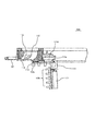
- FIG. 4 is an enlarged view showing the inner structure 400 of the decorative panel 107 in the direction along the arrow line CC of FIG.
- FIG. 5 is a schematic view of the inner structure 500 when the suction grill 109b is opened for maintenance or the like.
- FIG. 6 is an enlarged view of the internal structure 600 in which the end portion corresponding to the decorative panel 107 shown in FIGS. 4 and 5 is enlarged in the direction of the cutting line DD of FIG.
- FIG. 7 is a diagram showing an exemplary modification.
- FIG. 8 is a diagram showing an edge structure of an indoor unit 800 of a conventional ceiling-embedded
- FIG. 1 shows a schematic cross-sectional view of the indoor unit 100 of the exemplary embodiment.
- the indoor unit 100 shown in FIG. 1 is an indoor unit 100 of a ceiling-embedded air conditioner, and drives a heat exchanger 103, a fan 105, and a fan 105 in a housing 102 of the indoor unit 100. Accommodates the fan motor 106 for the purpose.
- the indoor air is sucked in the direction of the arrow A, directed to the heat exchanger 103 according to the airflow generated by the fan 105, and exchanges heat with the heat exchange medium circulating in the heat exchanger 103.
- the conditioned air after heat exchange is discharged from the outlet 108 in the direction of arrow B toward the room, which is an exemplary air conditioned space.
- a drain pan 104 is arranged below the heat exchanger 103 to collect drain water, dirt, and the like from the heat exchanger 103.
- a decorative panel 107 is installed on the indoor side of the housing 102.
- a grill 109 is detachably installed on the indoor side of the decorative panel 107.
- the grill 109 is composed of a dummy grill 109a arranged at at least one end thereof and a suction grill 109b.
- the dummy grill 109a of the grill 109 extends so as to be adjacent to the air outlet 108 in order to improve the design of the indoor side of the indoor unit 100.
- adjacent to the outlet 108 means that the dummy grill 109a is located in the region between the outlet 108 and the suction grill 109b, and is located between the outlet 108 and the suction grill 109b. It means extending from the end of the suction grill 109b with a width of at least 1/2 of the width. Further, the dummy grill 109a is detachably fixed to the decorative panel 107, and the mounting direction thereof can be fixed to a position rotated by, for example, 90 ° with respect to the decorative panel 107.
- one end of the suction grill 109b is connected to one dummy grill 109a via a hinge mechanism, and the opposite end is connected to the decorative panel 107 via a latch mechanism. ..
- the suction grill 109b is fixed to the decorative panel 107 by the dummy grill 109a and the latch mechanism.
- the suction grill 109b and the dummy grills 109a arranged at both ends thereof increase the area of the grill 109 and reduce the weight of the suction grill 109b. Therefore, in the present embodiment as an example, the design of the indoor unit 100 can be improved, the movable portion of the grill 109 can be reduced in weight, and the operability can be improved.
- An outlet 108 is formed on the outer edge of the grill 109 of the decorative panel 107.
- a heat insulating material 110 is arranged at the inner end and the outer end of the air outlet 108 to prevent dew condensation. The air after air conditioning is blown out from the outlet 108 in the direction of the arrow line B to achieve indoor air conditioning.
- the suction grill 109b of the grill 109 is rotated clockwise downward on the paper surface. By exposing the inside of the indoor unit 100, access to the inside of the air conditioner 100 is possible.
- FIG. 2 shows an exemplary embodiment 200 in which the suction grill 109b of the indoor unit 100 is opened in an exemplary embodiment.
- One end of the suction grill 109b is engaged with the dummy grill 109a via a hinge mechanism, and the other end is held with the decorative panel 107 by a latch mechanism.
- the latch mechanism arranged on the right side of the paper surface is released, one end of the suction grill 109b is opened, and the operator can move the movable end of the suction grill 109b.
- the suction grill 109b is rotated downward on the paper surface while holding the portion.
- a suspension wire 109c whose one end is fixed to the decorative panel 107 is connected to the central portion of the suction grill 109b, and the suction grill 109b is held by the suspension wire 109c after being rotated to an allowable range of the suspension wire 109c. Will be done.
- the left end of the suction grille 109b on the paper surface is rotatably connected to the dummy grille 109a via a hinge mechanism.
- the suction grill 109b rotates via the hinge mechanism of the dummy grill 109a in response to the lowering of the right end portion thereof, and enables the suction grill 109b to rotate and move.
- FIG. 3 shows a suction grill structure 300 when the indoor unit 100 of the exemplary embodiment is viewed from the indoor side.
- the grill 109 includes a suction grill 109b and dummy grills 109a arranged at both ends of the suction grill 109b.
- the grill 109 has a substantially square shape when viewed from the indoor side, and is expanded to a position adjacent to the air outlet 108 formed at the edges of the decorative panel 107 in the four directions.
- the suction grill 109b arranged at the center of the grill 109 is a rectangle having long sides in the left-right direction of the paper surface in the illustrated embodiment.
- latch mechanisms 115 are formed at both ends on the short side side of the suction grill 109b.
- the latch mechanism 115 fixes the suction grill 109b to the decorative panel 107. Therefore, the suction grill 109b has a smaller area than the apparent area of the grill 109, and the weight is reduced to improve the operability.
- the dummy grill 109a is detachable from the decorative panel 107, and can correspond to a change in the extending direction of the louver of the grill 109 with respect to the decorative panel 107.
- the suction grill 109b can change its opening / closing direction, which improves workability and maintainability.
- FIG. 4 is an enlarged view showing the inner structure 400 of the decorative panel 107 when the decorative panel 107 has a cross section in a direction parallel to the paper surface at the position of the arrow CC in FIG.
- the exemplary embodiment shown in FIG. 4 corresponds to the end where the hinge mechanism is formed.
- an air outlet 108 is formed inside the decorative panel 107, and the wind direction plate 112 is movably held inside the air outlet 108 by a drive mechanism (not shown) via a pivot mechanism 113. To control the direction of the conditioned air blown into the room.
- Insulation materials 110 are arranged on both sides of the air outlet 108 to prevent dew condensation in the vicinity of the air outlet 108.
- the dummy grill 109a is installed between the outlet 108 and the suction grill 109b in an area that has conventionally existed as a space that deteriorates the design, and the design of the indoor side of the indoor unit 100 is improved. In addition to improving it, it also improves operability during maintenance.
- a filter 111 is placed on the indoor side of the suction grill 109b on the indoor side of the indoor unit 100, and a louver extending parallel to the louver structure of the dummy grill 109a is formed on the indoor side of the grill 109 to form the dummy grill 109a and the suction grill.
- the sense of unity with 109b is improved.
- the dummy grill 109a of the present embodiment is arranged so as to extend inward from a position close to the outlet 108 and its inner end extending to the end of the suction grill 109b.
- a hinge 114 that engages with the inner end of the dummy grill 109a is formed at the outer end of the suction grill 109b, and the suction grill 109b cooperates with the hinge receiving portion 114d formed on the dummy grill 109a. It is rotatably held around the dummy grill 109a.
- the hinge 114 has a tip portion 114a that bends and extends toward the indoor side on the upper side of the dummy grill 109a, and an end surface of the suction grill 109b toward the indoor unit side.
- a U-shaped structure having a substantially U-shaped cross section including an extended base portion 114b and a connecting portion 114c that connects the tip portion 114a and the base portion 114b is provided.
- a second U-shaped structure having the same shape is also arranged on the front side of the paper surface of FIG. 4, and both paired U-shaped structures have a tip portion 114a. It is connected in the vertical direction of the paper. Further, both U-shaped structures to be paired are vertically oriented on the paper surface by the base 114b, and an aperture (not shown) for accommodating the hinge stopper 114e is formed between both U-shaped structures.
- the dummy grill 109a is formed with a hinge receiving portion 114d for receiving the tip portion 114a of the hinge 114, and a hinge stopper 114e is formed at the end portion on the suction grill 109b side.
- the hinge 114 accommodates the hinge stopper 114e between the apertures and can move in the left-right direction on the paper surface.
- a beam structure integrally formed with the decorative panel 107 extends in the vertical direction of the paper surface on the upper portion of the hinge 114, and regulates the amount of movement of the hinge 114 in the vertical direction of the paper surface.
- FIG. 5 shows a schematic view of the inner structure 500 when the suction grill 109b is opened for maintenance or the like.
- the suction grill 109b can be rotated by releasing the latch mechanism formed at the end portion on the opposite side.
- the hinge 114 is pulled out to the right hand side of the paper surface in a nearly horizontal arrangement, and the suction grill 109b is moved to a position where the tip 114a of the hinge 114 and the facing surfaces of the hinge receiving portion 114d are adjacent to each other. Is pulled out laterally.
- the suction grill 109b rotates clockwise with the tip 114a as a fulcrum, so that the suction grill 109b can rotate. Further, with the suction grill 109b rotated to a predetermined position, the suction grill 109b is lifted above the paper surface to release the engagement between the aperture formed on the hinge 114 and the hinge stopper 114e, and the suction grill 109b is released. Is removed from the decorative panel 107. With the above configuration, the suction grill 109b is detachably configured with respect to the decorative panel 107.
- the operator accesses the inside of the indoor unit 100, replaces and cleans the filter 111, and performs maintenance and inspection of the internal elements of the indoor unit 100. .. Although the entire area of the grill 109 is increased, the weight of the suction grill 109b is lighter than the area on the outer surface, so that the operability and workability can be improved while improving the design.
- FIG. 6 is an enlarged view showing an enlarged view of the internal structure 600 of the end portion including the latch mechanism 115 arranged on the side facing the end portion of the decorative panel 107 shown in FIGS. 4 and 5.
- the latch mechanism 115 shown in FIG. 6 cuts the decorative panel 107 along the cutting line DD along the vertical direction of the paper surface of FIG. 1, and corresponds to the internal structure 600 of the cross section seen from the arrow-viewing direction.
- the suction grills 109b on the side of the decorative panel 107 facing the ends shown in FIGS. 4 and 5 have suction grills 109b on the decorative panel 107 at both ends separated in the direction of the cutting line DD of FIG.
- a latch mechanism 115 having a function of removably holding the latch mechanism 115 is formed.
- an air outlet 108 is formed at the end of the decorative panel, and the wind direction plate 112 is rotatably held inside the air outlet 108 by the pivot mechanism 113. Similar to the embodiment shown in FIG. 5, the conditioned air is blown toward the room to enable the air conditioned of the room air.
- the heat insulating material is arranged on both sides of the air outlet 108 in the same manner as the end portion on the opposite side, and the suction grill 109b extends below the heat insulating material 110 arranged inside.
- the suction grill 109b extends to a position adjacent to the air outlet 108 in order to improve the design of the interior side of the decorative panel 107.
- the opposite end of the suction grill 109b extends to the outlet 108 on the opposite side as well, and in the exemplary embodiment described, the suction grill 109b is rectangular as shown in FIG. It is said that.
- a latch mechanism 115 for jointly locking the suction grill 109b is formed at the end of the suction grill 109b and the short side end of the decorative panel 107 facing the suction grill 109b.
- the latch mechanism 115 includes an operation hook 115a, an accommodation space 115c, and an engaging portion 115b integrated with the decorative panel 107.
- the accommodating space 115c accommodates an elastic body 115d for urging the operation hook 115a.
- the operation hook 115a extends outward along the upper surface of the suction grill 109b from a knob protruding from between the louvers of the suction grill 109b, bends upward at an appropriate position of the suction grill 109b, and bends outward again. It has an extended structure.
- the opposite end of the knob of the operating hook 115a constitutes an engaging claw 115e that engages the decorative panel 107.
- the accommodation space 115c is defined by a portion of the operation hook 115a extending along the upper surface of the suction grill 109b and a protruding portion rising from the inner surface of the suction grill 109b.
- an elastic body 115d called a spring for urging the engaging claw 115e of the operation hook 115a so as to project outward is arranged.
- the engaging claw 115e of the operation hook 115a fits into the engaging portion 115b formed on the decorative panel 107 to fix the suction grill 109b.
- the operator moves the suction grill 109b in order to access the inside of the indoor unit 100, the operator first moves the operation hook 115a in the direction of the arrow line E, pulls out the engaging claw 115e from the engaging portion 115b, and pulls out the suction grill 109b. To the bottom of the paper. After that, the operator can access the inside of the indoor unit 100 by rotating the suction grill 109b to the lower side of the paper surface and removing the suction grill 109b as needed.
- the hanging wire 109c shown in FIG. 2 is fixed at an appropriate position of the suction grill 109b, which enables the suction grill 109b to be held at an appropriate position and prevents the suction grill 109b from dropping unintentionally. It is possible to prevent it.
- the mounting direction of the dummy grill 109a with respect to the decorative panel 107 is rotated, for example.
- the grill 109 is formed in a substantially square shape, but the portion excluding the dummy grill 109a is formed in a substantially rectangular shape. Therefore, by rotating the mounting direction of the dummy grill 109a with respect to the decorative panel 107 by 90 °, the direction in which the louver of the grill 109 extends can be changed. Therefore, it is possible to improve the workability when the indoor unit 100 is installed indoors while considering the design.
- FIG. 7 shows an exemplary modification.
- the members having the same or the same function as those in the above-described embodiment will be described with the same reference numerals, and the description thereof will be omitted.
- the modification shown in FIG. 7 is an embodiment in which the grill 109 of the indoor unit 700 can be raised and lowered by the lifting motor 713 and the hanging wire.
- the indoor unit 700 shown in FIG. 7 houses the heat exchanger 103, the fan 105, and the fan motor 106 for driving the fan 105 in the housing 102 of the indoor unit 100.
- the indoor air flows in the direction of the arrow A, is directed to the heat exchanger 103 according to the airflow generated by the fan 105, and exchanges heat with the refrigerant circulating in the heat exchanger 103.
- the conditioned air after heat exchange is discharged from the outlet 108 toward the room in the direction of arrow B.
- a drain pan 104 is arranged below the heat exchanger 103 to collect the drain water of the heat exchanger 103.
- a decorative panel 107 is installed on the indoor side of the housing 102, and a grill 109 is detachably installed on the indoor side of the decorative panel 107.
- the grill 109 includes a suction grill 109b held up and down by an elevating motor 713, and dummy grills 109a arranged at both ends thereof.
- the inner portion of the dummy grill 109a is formed separately from the dummy grill 109a as a suction grill 109b formed in a rectangular shape, more specifically, a rectangular shape.
- An accommodating portion 715 for accommodating the suction grill 109b is formed.
- the suction grill 109b is formed with wire attachment portions 710a to 710d formed at appropriate positions at the four corners of the suction grill 109b.
- FIG. 7 shows only the wire attachment portions 710a and 710b arranged on the front side of the paper surface.
- a suspension wire 712 for holding the suction grill 109b so as to be able to move up and down is fixed via a wire holding mechanism.
- a filter 111 is placed on the surface of the suction grill 109b facing the indoor unit 100.
- an elevating motor 713 and a drum 714 are arranged by an appropriate mounting member.
- the elevating motor 713 rotates the drum 714 to elevate and elevate the suction grill 109b fixed to the other end of the suspension wire 712. Further, the elevating motor 713 pulls up the suction grill 109b to a position where the dummy grill 109a and the suction grill 109b are integrated during the normal operation of the indoor unit 100.
- the elevating motor 713 is arranged on the left and right sides of the housing 102, but the elevating motor 713 may be arranged on one side of the housing 102, for example, according to the configuration of Patent Document 1.
- the suspension wire 712 may be driven by one elevating motor 713 on one side and by another elevating motor 713 in which two on the other side are synchronously driven with one elevating motor 713.
- the suspension wires 712 may be wound and unwound by one elevating motor 713, or four wires may be wound and unwound by independent elevating motors 713. ..
- the elevating motor 713 is activated in response to a command from a remote controller (not shown) for controlling the indoor unit 100.
- the suction grill 109b is lowered to a predetermined height so that the operator can access the inside of the housing 102.
- the grill 109 is formed so as to extend close to the air outlet 108 formed in the four directions of the decorative panel 107 from the viewpoint of design. Therefore, the grill 109 of the present embodiment increases the apparent area of the grill 109 as a whole to improve the design.
- the grill 109 is separately configured as the dummy grill 109a and the suction grill 109b to reduce the weight and space, so that the design can be improved while improving the operability and workability of the suction grill 109b.
- the dummy grill 109a can be formed in the four directions of the decorative panel 107, and the suction grill 109b can be further reduced in weight.
- a stopper mechanism can be added that stops the rotation of the elevating motor 713 to prevent reverse rotation when the suction grill 109b is raised to a predetermined position by the elevating motor 713.
- a conventional manual or electric latch mechanism for fixing the suction grill 109b to the decorative panel 107 can also be formed on the grill 109.
- a ceiling-embedded air conditioner having a lightweight suction grill structure while making the grill look wider and easier to open and close is provided. be able to.
Abstract
[Problem] To provide a ceiling-mounted embedded-type air conditioner. [Solution] The present ceiling-mounted embedded-type air conditioner includes: an indoor unit 100 provided with a fan 105, a fan motor 106, and a heat exchanger 103; a decorative panel 107 attached to the indoor unit 100 so as to face the air-conditioned space; and a grille 109 attached to the decorative panel 107. The grille 109 extends to a position neighboring an outlet 108 formed in the decorative panel 107, and at least one end of the grille 109 is provided with a dummy grille 109a that is a separate body from the grille 109 and that neighbors the outlet 108.
Description
本発明は、空気調和機に関し、より詳細には、天井埋込型空気調和機の下部に装着される化粧パネルを備える天井埋込型空気調和機に関する。
The present invention relates to an air conditioner, and more particularly to a ceiling-embedded air conditioner having a decorative panel mounted on the lower part of the ceiling-embedded air conditioner.
これまでデザイン性を重視する空間での室内ユニットは、ダクトタイプユニットが採用されてきたが、近年安価にビルを建設したい需要の増加に伴い、ダクト工事不要の天井カセット型が要望されることが増加している。この要望に対応するため、デザイン面においてダクトタイプユニットと、従来の天井カセット型の中間を担う化粧パネルが提案されている。
Until now, duct type units have been adopted as indoor units in spaces where design is important, but with the increasing demand for inexpensive building construction in recent years, ceiling cassette types that do not require duct construction are required. It has increased. In order to meet this demand, a decorative panel that plays an intermediate role between the duct type unit and the conventional ceiling cassette type has been proposed in terms of design.
天井埋込型空気調和機の化粧パネルは、デザイン上の観点から吸込みグリルを化粧パネル外周部に設けられた吹出口付近まで拡大した構造が好まれる。一方で吹出口の周囲には、空気調和された空気の吹出しに伴う結露防止などのため一定厚み以上の断熱材を設ける必要がある。
From a design point of view, the decorative panel of the ceiling-embedded air conditioner is preferably a structure in which the suction grill is expanded to the vicinity of the air outlet provided on the outer periphery of the decorative panel. On the other hand, it is necessary to provide a heat insulating material having a certain thickness or more around the air outlet to prevent dew condensation due to air-conditioned air blowing.
図8は、従来の天井埋込型空気調和機の室内機800の概略的な構造を示す。従来の室内機800は、天井(図示せず)に隣接して設置される化粧パネル801が室内側に配置される。化粧パネル801の内部には、吹出口802が形成され、吹出口802の内部には、適切な枢軸機構807および駆動機構を介して風向板806が配置されている。また、室内機800の本体809内には、熱交換器810と、ドレンパン811とが配置されている。熱交換器810は、室外機(図示せず)から送付される熱交換媒体と室内空気との間で熱交換を行う。熱交換後の調和空気は、吹出口802から室内へと噴出され、室内の空気調和を行う。ドレンパン811は、熱交換器810からのドレン水を受けるため、熱交換器810の下側に配置されている。
FIG. 8 shows a schematic structure of an indoor unit 800 of a conventional ceiling-embedded air conditioner. In the conventional indoor unit 800, the decorative panel 801 installed adjacent to the ceiling (not shown) is arranged on the indoor side. An air outlet 802 is formed inside the decorative panel 801, and an air direction plate 806 is arranged inside the air outlet 802 via an appropriate pivot mechanism 807 and a drive mechanism. Further, a heat exchanger 810 and a drain pan 811 are arranged in the main body 809 of the indoor unit 800. The heat exchanger 810 exchanges heat between the heat exchange medium sent from the outdoor unit (not shown) and the indoor air. The conditioned air after heat exchange is ejected from the outlet 802 into the room to harmonize the air in the room. The drain pan 811 is arranged below the heat exchanger 810 in order to receive the drain water from the heat exchanger 810.
吹出口802の両側には、結露を防止するための断熱材805が配置されており、内側の断熱材805の近くにまで、吸込みグリル803が延びている。吸込みグリル803は、室内空気を室内機800内に導入するための開口を備え、吸込みグリル803の室内機800側には、フィルタ(図示せず)が載置されている。
Insulation material 805 for preventing dew condensation is arranged on both sides of the air outlet 802, and the suction grill 803 extends close to the inner heat insulating material 805. The suction grill 803 is provided with an opening for introducing indoor air into the indoor unit 800, and a filter (not shown) is placed on the indoor unit 800 side of the suction grill 803.
吸込みグリル803は、フィルタの清掃や交換、または室内機800のメンテナンスの理由から、開閉する必要があり、従来の化粧パネル801では、吸込みグリル803の端部に化粧パネル801に係合するヒンジ808が配置される。メンテナンスなどの要求に応じて、吸込みグリル803の紙面右手側端部付近に配置されたノブが操作されて、化粧パネル801との連結が解除される。その後、作業者の操作によりヒンジ808が化粧パネル801に対して回転されると、吸込みグリル803は、紙面下側へ向かって時計回りに回転する。
The suction grill 803 needs to be opened and closed for cleaning or replacement of the filter or maintenance of the indoor unit 800. In the conventional decorative panel 801, the hinge 808 that engages with the decorative panel 801 at the end of the suction grill 803. Is placed. In response to a request for maintenance or the like, a knob arranged near the right-hand side end of the paper surface of the suction grill 803 is operated to release the connection with the decorative panel 801. After that, when the hinge 808 is rotated with respect to the decorative panel 801 by the operation of the operator, the suction grill 803 rotates clockwise toward the lower side of the paper surface.
図8の構成の下で吸込みグリル803を吹出口802付近まで拡大しようとした場合、断熱材805の容積のため、開閉の軸となるヒンジ808を設けるスペースを確保することが困難となる。このため、単純な構造を用いて、吸込みグリル803の開閉動作ができないという問題が生じていた。この観点から見ると、吹出口802と吸込みグリル803との間に形成された領域804は、化粧パネル801の室内側デザインから見てデザイン性を悪化させる領域と言うことができ、ヒンジ構造の改善により有効利用することができる余地が残されている。
When the suction grill 803 is expanded to the vicinity of the air outlet 802 under the configuration of FIG. 8, it becomes difficult to secure a space for providing the hinge 808 which is the axis of opening and closing due to the volume of the heat insulating material 805. Therefore, there has been a problem that the suction grill 803 cannot be opened and closed by using a simple structure. From this point of view, the region 804 formed between the outlet 802 and the suction grill 803 can be said to be a region that deteriorates the design of the decorative panel 801 from the viewpoint of the interior design, and the hinge structure is improved. There is still room for effective use.
また、吸込みグリル803を吹出口802付近まで拡大すると、従来の吸込みグリルよりも吸込みグリル803が大型となり、この結果、吸込みグリル803の重量が増加し、昇降グリル付きの化粧パネルに同一の構成を採用した際に、吸込みグリル昇降用モータの出力が不足する懸念もあった。
Further, when the suction grill 803 is expanded to the vicinity of the outlet 802, the suction grill 803 becomes larger than the conventional suction grill, and as a result, the weight of the suction grill 803 increases, and the same configuration is applied to the decorative panel with the elevating grill. When adopted, there was a concern that the output of the suction grill elevating motor would be insufficient.
これまで室内機の内部の作業を行うため種々の構成が検討されており、例えば国際公開WO2018/179136号パンフレット(特許文献1)には、室内機の内部への作業性の改善を目的として、化粧パネルの意匠側に設けられた吸込みグリルと、吸込グリルの左右に設けられたサイドパネルとを備え、化粧パネルが本体に取り付いた状態で、回動して開いた吸込グリルにより化粧パネルに着脱自在に取り付けられたサイドパネルを取り外すことが可能な天井埋込型空気調和機を記載する。
Various configurations have been studied so far for working inside the indoor unit. For example, in the pamphlet of WO2018 / 179136 (Patent Document 1), the international publication WO2018 / 179136 has the purpose of improving the workability inside the indoor unit. It is equipped with a suction grill provided on the design side of the decorative panel and side panels provided on the left and right sides of the suction grill. Describes a ceiling-embedded air conditioner in which the freely attached side panel can be removed.
特許文献1に記載された室内機は、室内機内部へのアクセス性を向上することができるものの、デザイン性には関係ないサイドパネルを追加するものであり、却って室内機のデザイン性を低下させてしまう。また、吸込みグリルを吹出口の近くまで延ばすことで、デザイン性を改善することを目的とするものではない。
The indoor unit described in Patent Document 1 can improve the accessibility to the inside of the indoor unit, but adds a side panel which is not related to the design, and rather lowers the design of the indoor unit. It ends up. Further, the purpose is not to improve the design by extending the suction grill to the vicinity of the air outlet.
また、特開平2-171526号公報(特許文献2)は、前面グリルの一端にサイドグリルを設けた複合空気調和機を記載する。しかしながら、特許文献2は、天井埋込型空気調和機の室内機のデザイン性を改善することを課題とするものではない。
Further, Japanese Patent Application Laid-Open No. 2-171526 (Patent Document 2) describes a composite air conditioner in which a side grill is provided at one end of a front grill. However, Patent Document 2 does not aim to improve the design of the indoor unit of the ceiling-embedded air conditioner.
本発明は、上記問題点に鑑みてなされたものであり、本発明は、吸込みグリルを広く見せつつ、開閉を容易とし、吸込みグリルの大面積化にも関わらず、軽量化された吸込みグリルの構造を備える天井埋込型空気調和機を提供することを目的とする。
The present invention has been made in view of the above problems, and the present invention makes it easy to open and close the suction grill while making the suction grill look wider, and despite the increase in the area of the suction grill, the weight of the suction grill is reduced. It is an object of the present invention to provide a ceiling-embedded air conditioner having a structure.
すなわち、本発明によれば、
ファンと、ファンモータと、熱交換器とを含む室内機を備えた天井埋込型空気調和機であって、
前記室内機は、
空気調和空間に向けて取付けられ、吸込口及び吹出口を有する化粧パネルと、
前記化粧パネルに取付けられるグリルと
を含み、
前記グリルは、前記吸込口に設けられる吸込みグリルと、前記吸込みグリルの少なくとも一方の端部から延び、前記吸込口と前記吹出口の間に設けられるダミーグリルとを有する、
天井埋込型空気調和機が提供される。 That is, according to the present invention.
A ceiling-embedded air conditioner equipped with an indoor unit including a fan, a fan motor, and a heat exchanger.
The indoor unit is
A decorative panel that is installed toward an air-conditioned space and has a suction port and an outlet.
Including the grill attached to the decorative panel
The grill has a suction grill provided at the suction port and a dummy grill extending from at least one end of the suction grill and provided between the suction port and the air outlet.
A ceiling-embedded air conditioner is provided.
本発明によれば、デザイン性の改善された吸込みグリル構造を備える天井埋込型空気調和機を提供することができる。
According to the present invention, it is possible to provide a ceiling-embedded air conditioner having a suction grill structure with improved design.
以下、本発明を例示的実施形態により説明するが、本発明は後述する実施形態に限定されるものではない。また、図面は、本発明の理解を容易にするために使用され、本発明を限定するために添付されたものと解釈されるものではない。さらに、用語「近く」、「近接して」、または「隣接して」は、当業者において「近く」、「近接して」、または「隣接して」と理解される通常の意味で使用され、必ずしも実際に接していることを意味するものではない。
Hereinafter, the present invention will be described with reference to exemplary embodiments, but the present invention is not limited to the embodiments described later. In addition, the drawings are used to facilitate the understanding of the present invention and are not construed as being attached to limit the present invention. In addition, the terms "near", "close", or "adjacent" are used in the usual sense as understood by those skilled in the art as "near", "close", or "adjacent". , Does not necessarily mean that they are actually in contact.
図1は、例示的実施形態の室内機100の概略的断面図を示す。図1に示す室内機100は、天井埋込型空気調和機の室内機100とされており、室内機100の筐体102内に、熱交換器103と、ファン105と、ファン105を駆動するためのファンモータ106とを収容する。室内空気は、矢線Aの方向へと吸い込まれ、ファン105が生成する気流にしたがって熱交換器103へと向けられ、熱交換器103内を循環する熱交換媒体と熱交換する。
FIG. 1 shows a schematic cross-sectional view of the indoor unit 100 of the exemplary embodiment. The indoor unit 100 shown in FIG. 1 is an indoor unit 100 of a ceiling-embedded air conditioner, and drives a heat exchanger 103, a fan 105, and a fan 105 in a housing 102 of the indoor unit 100. Accommodates the fan motor 106 for the purpose. The indoor air is sucked in the direction of the arrow A, directed to the heat exchanger 103 according to the airflow generated by the fan 105, and exchanges heat with the heat exchange medium circulating in the heat exchanger 103.
熱交換後の調和空気は、吹出口108から矢線Bの方向へと、例示的な空気調和空間である室内に向けて排出される。熱交換器103の下方には、ドレンパン104が配置されており、熱交換器103のドレン水や汚れなどを回収する。
The conditioned air after heat exchange is discharged from the outlet 108 in the direction of arrow B toward the room, which is an exemplary air conditioned space. A drain pan 104 is arranged below the heat exchanger 103 to collect drain water, dirt, and the like from the heat exchanger 103.
筐体102の室内側には、化粧パネル107が設置されている。化粧パネル107の室内側には、グリル109が着脱自在に設置されている。グリル109は、少なくとも一方の端部に配置されたダミーグリル109aと、吸込みグリル109bとから構成されている。グリル109のダミーグリル109aは、室内機100の室内側のデザイン性を改善するため、吹出口108に隣接するように延びる。
A decorative panel 107 is installed on the indoor side of the housing 102. A grill 109 is detachably installed on the indoor side of the decorative panel 107. The grill 109 is composed of a dummy grill 109a arranged at at least one end thereof and a suction grill 109b. The dummy grill 109a of the grill 109 extends so as to be adjacent to the air outlet 108 in order to improve the design of the indoor side of the indoor unit 100.
なお、本開示の好ましい実施形態において、吹出口108に隣接するとは、ダミーグリル109aが、吹出口108と、吸込みグリル109bとの間の領域に、吹出口108と、吸込みグリル109bとの間の幅の少なくとも1/2以上の幅をもって吸込みグリル109bの端部から延びることを意味する。また、ダミーグリル109aは、化粧パネル107に対して着脱自在に固定され、その取付け方向は、化粧パネル107に対して例えば90°回転した位置にも固定可能とされている。
In a preferred embodiment of the present disclosure, adjacent to the outlet 108 means that the dummy grill 109a is located in the region between the outlet 108 and the suction grill 109b, and is located between the outlet 108 and the suction grill 109b. It means extending from the end of the suction grill 109b with a width of at least 1/2 of the width. Further, the dummy grill 109a is detachably fixed to the decorative panel 107, and the mounting direction thereof can be fixed to a position rotated by, for example, 90 ° with respect to the decorative panel 107.
また、吸込みグリル109bは、一方の端部が、一方のダミーグリル109aにヒンジ機構を介して連結されており、対向する側の端部は、ラッチ機構を介して化粧パネル107に連結されている。ダミーグリル109aとラッチ機構により、吸込みグリル109bは、化粧パネル107に固定される。吸込みグリル109bおよびその両端に配置されたダミーグリル109aは、グリル109の面積を増大させると共に、吸込みグリル109bの重量を削減する。このため例示的な本実施形態では、室内機100のデザイン性を改善すると共に、グリル109の可動部分を軽量化し、操作性を改善することができる。
Further, one end of the suction grill 109b is connected to one dummy grill 109a via a hinge mechanism, and the opposite end is connected to the decorative panel 107 via a latch mechanism. .. The suction grill 109b is fixed to the decorative panel 107 by the dummy grill 109a and the latch mechanism. The suction grill 109b and the dummy grills 109a arranged at both ends thereof increase the area of the grill 109 and reduce the weight of the suction grill 109b. Therefore, in the present embodiment as an example, the design of the indoor unit 100 can be improved, the movable portion of the grill 109 can be reduced in weight, and the operability can be improved.
化粧パネル107のグリル109の外側縁部には、吹出口108が形成されている。吹出口108の内側端および外側端には結露防止などのため、断熱材110が配置されている。空気調和後の空気は、吹出口108から矢線Bの方向へと吹き出され、室内の空気調和を達成する。
An outlet 108 is formed on the outer edge of the grill 109 of the decorative panel 107. A heat insulating material 110 is arranged at the inner end and the outer end of the air outlet 108 to prevent dew condensation. The air after air conditioning is blown out from the outlet 108 in the direction of the arrow line B to achieve indoor air conditioning.
図1に示した室内機100のフィルタ交換、清掃、点検、または部品交換などの際には、例示的な本実施形態ではグリル109のうち吸込みグリル109bを紙面下側に時計回りに回転移動させて、室内機100の内部を露出させることで、空調機100の内部へのアクセスを可能としている。
When replacing, cleaning, inspecting, or replacing parts of the indoor unit 100 shown in FIG. 1, in the present embodiment, the suction grill 109b of the grill 109 is rotated clockwise downward on the paper surface. By exposing the inside of the indoor unit 100, access to the inside of the air conditioner 100 is possible.
図2は、例示的な実施形態において室内機100の吸込みグリル109bを開いた例示的態様200を示す。吸込みグリル109bの一端は、ダミーグリル109aに対してヒンジ機構を介して係合されており、他端は、化粧パネル107に対してラッチ機構により保持されている。図2に示す例示的な実施形態において吸込みグリル109bを開く場合には、紙面右側に配置されたラッチ機構を解除して、吸込みグリル109bの一端を開放し、作業者が吸込みグリル109bの可動端部を保持しながら吸込みグリル109bを紙面下側に回転させる。
FIG. 2 shows an exemplary embodiment 200 in which the suction grill 109b of the indoor unit 100 is opened in an exemplary embodiment. One end of the suction grill 109b is engaged with the dummy grill 109a via a hinge mechanism, and the other end is held with the decorative panel 107 by a latch mechanism. When opening the suction grill 109b in the exemplary embodiment shown in FIG. 2, the latch mechanism arranged on the right side of the paper surface is released, one end of the suction grill 109b is opened, and the operator can move the movable end of the suction grill 109b. The suction grill 109b is rotated downward on the paper surface while holding the portion.
吸込みグリル109bの中央部には、化粧パネル107に一端が固定された吊りワイヤ109cが連結されていて、吸込みグリル109bは、吊りワイヤ109cの許容する範囲まで回動した後、吊りワイヤ109cにより保持される。
A suspension wire 109c whose one end is fixed to the decorative panel 107 is connected to the central portion of the suction grill 109b, and the suction grill 109b is held by the suspension wire 109c after being rotated to an allowable range of the suspension wire 109c. Will be done.
一方、図2に示した例示的な実施形態では、吸込みグリル109bの紙面左側の端部は、ダミーグリル109aに対してヒンジ機構を介して回動自在に連結されている。吸込みグリル109bは、その右側の端部の下降に対応してダミーグリル109aのヒンジ機構を介して回転し、吸込みグリル109bの回転移動を可能とする。
On the other hand, in the exemplary embodiment shown in FIG. 2, the left end of the suction grille 109b on the paper surface is rotatably connected to the dummy grille 109a via a hinge mechanism. The suction grill 109b rotates via the hinge mechanism of the dummy grill 109a in response to the lowering of the right end portion thereof, and enables the suction grill 109b to rotate and move.
図3は、例示的な実施形態の室内機100を室内側から見た場合の吸込みグリル構造300を示す。図3に示すように、グリル109は、吸込みグリル109bと、吸込みグリル109bの両端に配置されたダミーグリル109aとを含んでいる。グリル109は、室内側から見上げた場合には概ね正方形の形状を有していて、化粧パネル107の4方向の縁部に形成された吹出口108に隣接する位置まで拡大されている。
FIG. 3 shows a suction grill structure 300 when the indoor unit 100 of the exemplary embodiment is viewed from the indoor side. As shown in FIG. 3, the grill 109 includes a suction grill 109b and dummy grills 109a arranged at both ends of the suction grill 109b. The grill 109 has a substantially square shape when viewed from the indoor side, and is expanded to a position adjacent to the air outlet 108 formed at the edges of the decorative panel 107 in the four directions.
このため、グリル109の中央部に配置される吸込みグリル109bは、図示する例示的な実施形態では紙面左右方向に長辺を有する長方形とされている。また、図3に示す例示的な実施形態では、吸込みグリル109bの短辺側の両端部には、ラッチ機構115が形成されている。ラッチ機構115は、吸込みグリル109bを化粧パネル107に固定する。このため、吸込みグリル109bは、グリル109の外見上の面積よりも小面積とされ、軽量化されることで操作性が改善されている。また、ダミーグリル109aは、化粧パネル107に対して着脱自在とされていて、化粧パネル107に対するグリル109のルーバの延在方向の変更に対応することが可能である。また、これに対応して、吸込みグリル109bは、その開閉方向を変更することが可能とされており、作業性および保守性を改善する。
Therefore, the suction grill 109b arranged at the center of the grill 109 is a rectangle having long sides in the left-right direction of the paper surface in the illustrated embodiment. Further, in the exemplary embodiment shown in FIG. 3, latch mechanisms 115 are formed at both ends on the short side side of the suction grill 109b. The latch mechanism 115 fixes the suction grill 109b to the decorative panel 107. Therefore, the suction grill 109b has a smaller area than the apparent area of the grill 109, and the weight is reduced to improve the operability. Further, the dummy grill 109a is detachable from the decorative panel 107, and can correspond to a change in the extending direction of the louver of the grill 109 with respect to the decorative panel 107. Correspondingly, the suction grill 109b can change its opening / closing direction, which improves workability and maintainability.
図4は、図1の矢線C-Cの位置において、化粧パネル107を紙面平行な方向に断面とした場合の化粧パネル107の内側構造400を示した拡大図である。図4に示した例示的な実施形態は、ヒンジ機構が形成される端部に相当する。図4に示すように、化粧パネル107の内側には、吹出口108が形成されており、吹出口108の内部には風向板112が枢軸機構113を介して図示しない駆動機構により可動に保持されて、室内に吹き出す調和空気の方向を制御する。
FIG. 4 is an enlarged view showing the inner structure 400 of the decorative panel 107 when the decorative panel 107 has a cross section in a direction parallel to the paper surface at the position of the arrow CC in FIG. The exemplary embodiment shown in FIG. 4 corresponds to the end where the hinge mechanism is formed. As shown in FIG. 4, an air outlet 108 is formed inside the decorative panel 107, and the wind direction plate 112 is movably held inside the air outlet 108 by a drive mechanism (not shown) via a pivot mechanism 113. To control the direction of the conditioned air blown into the room.
吹出口108の両側には断熱材110が配置され、吹出口108付近における結露などを防止している。本実施形態では、吹出口108と、吸込みグリル109bとの間に、従来ではデザイン性を悪化させる空間として存在していた領域にダミーグリル109aを設置し、室内機100の室内側のデザイン性を改善すると共に、メンテナンス時の操作性を改善するものである。
Insulation materials 110 are arranged on both sides of the air outlet 108 to prevent dew condensation in the vicinity of the air outlet 108. In the present embodiment, the dummy grill 109a is installed between the outlet 108 and the suction grill 109b in an area that has conventionally existed as a space that deteriorates the design, and the design of the indoor side of the indoor unit 100 is improved. In addition to improving it, it also improves operability during maintenance.
また、吸込みグリル109bの室内機100の側にはフィルタ111が載置され、グリル109の室内側にはダミーグリル109aのルーバ構造と平行に延びたルーバが形成されてダミーグリル109aと、吸込みグリル109bとの間の一体感を改善している。
Further, a filter 111 is placed on the indoor side of the suction grill 109b on the indoor side of the indoor unit 100, and a louver extending parallel to the louver structure of the dummy grill 109a is formed on the indoor side of the grill 109 to form the dummy grill 109a and the suction grill. The sense of unity with 109b is improved.
本実施形態のダミーグリル109aは、吹出口108に近接した位置から内側へと延び、その内側端部が、吸込みグリル109bの端部にまで延びるように配置される。一方、吸込みグリル109bの外側端部には、ダミーグリル109aの内側端部に係合するヒンジ114が形成されていて、吸込みグリル109bが、ダミーグリル109aに形成されたヒンジ受け部114dと協働してダミーグリル109aの周りに回動可能に保持されている。
The dummy grill 109a of the present embodiment is arranged so as to extend inward from a position close to the outlet 108 and its inner end extending to the end of the suction grill 109b. On the other hand, a hinge 114 that engages with the inner end of the dummy grill 109a is formed at the outer end of the suction grill 109b, and the suction grill 109b cooperates with the hinge receiving portion 114d formed on the dummy grill 109a. It is rotatably held around the dummy grill 109a.
さらに、例示的な本実施形態のヒンジ114を説明すると、ヒンジ114は、ダミーグリル109aの上側で室内側へと屈曲して延びる先端部114aと、吸込みグリル109bの端面から室内機側に向かって延びた基部114bと、先端部114aと基部114bとを連結する連結部114cとを含んだ断面が概ねU形状のU字型構造体を備える。
Further, explaining the hinge 114 of the present embodiment as an example, the hinge 114 has a tip portion 114a that bends and extends toward the indoor side on the upper side of the dummy grill 109a, and an end surface of the suction grill 109b toward the indoor unit side. A U-shaped structure having a substantially U-shaped cross section including an extended base portion 114b and a connecting portion 114c that connects the tip portion 114a and the base portion 114b is provided.
さらに例示的な実施形態のヒンジ114は、同一の形状を有する第2のU字型構造体が図4の紙面手前側にも配置され、ペアとなる両方のU字型構造体が先端部114aで紙面垂直方向に連結されている。また、ペアとなる両方のU字型構造体は、基部114bにより紙面垂直方向にされ、両方のU字型構造体の間にヒンジストッパ114eを収容するアパーチャ(図示せず)を形成する。
In the hinge 114 of the further exemplary embodiment, a second U-shaped structure having the same shape is also arranged on the front side of the paper surface of FIG. 4, and both paired U-shaped structures have a tip portion 114a. It is connected in the vertical direction of the paper. Further, both U-shaped structures to be paired are vertically oriented on the paper surface by the base 114b, and an aperture (not shown) for accommodating the hinge stopper 114e is formed between both U-shaped structures.
一方、ダミーグリル109aには、ヒンジ114の先端部114aを受けるためのヒンジ受け部114dが形成されていて、吸込みグリル109b側の端部にヒンジストッパ114eが形成されている。ヒンジ114は、アパーチャの間にヒンジストッパ114eを収容して紙面左右方向に移動可能である。また、ヒンジ114の上部には、化粧パネル107と一体に形成された梁構造体が、紙面垂直方向に延びていて、ヒンジ114の紙面上下方向の移動量を規制している。
On the other hand, the dummy grill 109a is formed with a hinge receiving portion 114d for receiving the tip portion 114a of the hinge 114, and a hinge stopper 114e is formed at the end portion on the suction grill 109b side. The hinge 114 accommodates the hinge stopper 114e between the apertures and can move in the left-right direction on the paper surface. Further, a beam structure integrally formed with the decorative panel 107 extends in the vertical direction of the paper surface on the upper portion of the hinge 114, and regulates the amount of movement of the hinge 114 in the vertical direction of the paper surface.
図5は、吸込みグリル109bをメンテンナンスなどのために開いた状態とした場合の内側構造500の概略図を示す。この場合、吸込みグリル109bは、対向する側の端部に形成されたラッチ機構が解除されることで回転可能とされる。また、吸込みグリル109bを移動する場合、ヒンジ114が水平に近い配置において紙面右手側に引き出され、ヒンジ114の先端部114aと、ヒンジ受け部114dの互いに対向する面が隣接する位置まで吸込みグリル109bが横方向に引き出される。
FIG. 5 shows a schematic view of the inner structure 500 when the suction grill 109b is opened for maintenance or the like. In this case, the suction grill 109b can be rotated by releasing the latch mechanism formed at the end portion on the opposite side. When moving the suction grill 109b, the hinge 114 is pulled out to the right hand side of the paper surface in a nearly horizontal arrangement, and the suction grill 109b is moved to a position where the tip 114a of the hinge 114 and the facing surfaces of the hinge receiving portion 114d are adjacent to each other. Is pulled out laterally.
その後、吸込みグリル109bの図示しない他端が紙面下側に移動されると、先端部114aを支点として吸込みグリル109bが時計方向に回転することで、吸込みグリル109bの回転が可能となる。また、吸込みグリル109bを所定の位置まで回転した状態で、吸込みグリル109bを紙面上方に持ち上げることでヒンジ114に形成されたアパーチャと、ヒンジストッパ114eとの間の係合が開放され、吸込みグリル109bが化粧パネル107から取り外される。以上の構成により吸込みグリル109bが、化粧パネル107に対して着脱自在に構成されている。
After that, when the other end of the suction grill 109b (not shown) is moved to the lower side of the paper surface, the suction grill 109b rotates clockwise with the tip 114a as a fulcrum, so that the suction grill 109b can rotate. Further, with the suction grill 109b rotated to a predetermined position, the suction grill 109b is lifted above the paper surface to release the engagement between the aperture formed on the hinge 114 and the hinge stopper 114e, and the suction grill 109b is released. Is removed from the decorative panel 107. With the above configuration, the suction grill 109b is detachably configured with respect to the decorative panel 107.
図2に示した状態、または吸込みグリル109bを取外した状態で作業者は、室内機100の内部へとアクセスし、フィルタ111の交換、洗浄の他、室内機100の内部要素の保守点検を行う。グリル109の全面面積は増大するものの、吸込みグリル109bの重量が外面上の面積よりも軽量化されているので、デザイン性を向上しつつ、操作性および作業性を改善できる。
In the state shown in FIG. 2 or with the suction grill 109b removed, the operator accesses the inside of the indoor unit 100, replaces and cleans the filter 111, and performs maintenance and inspection of the internal elements of the indoor unit 100. .. Although the entire area of the grill 109 is increased, the weight of the suction grill 109b is lighter than the area on the outer surface, so that the operability and workability can be improved while improving the design.
図6は、図4、図5に示した化粧パネル107の端部に対向する側に配置されたラッチ機構115を含む端部の内部構造600を拡大して示した拡大図である。なお、図6に示したラッチ機構115は、図1の紙面垂直方向に沿った切断線D-Dにおいて化粧パネル107を切断し、矢視方向から見た断面の内部構造600に相当する。化粧パネル107の図4、図5に示した端部に対向する側の吸込みグリル109bには、図1の切断線D-Dの方向に離間する両端部に、吸込みグリル109bを化粧パネル107に対して取外し自在に保持する機能を有するラッチ機構115が形成されている。
FIG. 6 is an enlarged view showing an enlarged view of the internal structure 600 of the end portion including the latch mechanism 115 arranged on the side facing the end portion of the decorative panel 107 shown in FIGS. 4 and 5. The latch mechanism 115 shown in FIG. 6 cuts the decorative panel 107 along the cutting line DD along the vertical direction of the paper surface of FIG. 1, and corresponds to the internal structure 600 of the cross section seen from the arrow-viewing direction. The suction grills 109b on the side of the decorative panel 107 facing the ends shown in FIGS. 4 and 5 have suction grills 109b on the decorative panel 107 at both ends separated in the direction of the cutting line DD of FIG. On the other hand, a latch mechanism 115 having a function of removably holding the latch mechanism 115 is formed.
図6の構造を説明すると、化粧パネルの端部には、吹出口108が形成され、吹出口108の内部には、風向板112が枢軸機構113により回転可能に保持されていて、図4、図5に示した実施形態と同様に、室内に向けて調和空気を吹出し、室内空気の空気調和を可能としている。
Explaining the structure of FIG. 6, an air outlet 108 is formed at the end of the decorative panel, and the wind direction plate 112 is rotatably held inside the air outlet 108 by the pivot mechanism 113. Similar to the embodiment shown in FIG. 5, the conditioned air is blown toward the room to enable the air conditioned of the room air.
吹出口108の両側には断熱材が対抗する側の端部と同様に配置され、内側に配置された断熱材110の下部には、吸込みグリル109bが延びている。吸込みグリル109bは、化粧パネル107の室内側のデザイン性を改善するために、吹出口108に隣接する位置にまで延びる。また、吸込みグリル109bの対向する側の端部は、同様に対向する側の吹出口108にまで延びていて、説明する例示的な実施形態では、吸込みグリル109bは、図3に示すような長方形とされている。
The heat insulating material is arranged on both sides of the air outlet 108 in the same manner as the end portion on the opposite side, and the suction grill 109b extends below the heat insulating material 110 arranged inside. The suction grill 109b extends to a position adjacent to the air outlet 108 in order to improve the design of the interior side of the decorative panel 107. Further, the opposite end of the suction grill 109b extends to the outlet 108 on the opposite side as well, and in the exemplary embodiment described, the suction grill 109b is rectangular as shown in FIG. It is said that.
一方、吸込みグリル109bの端部および化粧パネル107の吸込みグリル109bに対面する短辺側端部には、協働して吸込みグリル109bを係止するためのラッチ機構115が形成されている。ラッチ機構115は、操作フック115aと、収容空間115cと、化粧パネル107に一体とされた係合部115bとを含んで構成される。収容空間115cには、操作フック115aを付勢するための弾性体115dを収容する。
On the other hand, a latch mechanism 115 for jointly locking the suction grill 109b is formed at the end of the suction grill 109b and the short side end of the decorative panel 107 facing the suction grill 109b. The latch mechanism 115 includes an operation hook 115a, an accommodation space 115c, and an engaging portion 115b integrated with the decorative panel 107. The accommodating space 115c accommodates an elastic body 115d for urging the operation hook 115a.
操作フック115aは、吸込みグリル109bのルーバの間から突出するツマミから、吸込みグリル109bの上面に沿って外側に延び、吸込みグリル109bの適切な位置で上側に屈曲し、再度外側へと屈曲して延びた構造を有する。操作フック115aのツマミの反対側の端部は、化粧パネル107に係合する係合爪115eを構成する。
The operation hook 115a extends outward along the upper surface of the suction grill 109b from a knob protruding from between the louvers of the suction grill 109b, bends upward at an appropriate position of the suction grill 109b, and bends outward again. It has an extended structure. The opposite end of the knob of the operating hook 115a constitutes an engaging claw 115e that engages the decorative panel 107.
また、収容空間115cは、操作フック115aの吸込みグリル109bの上面に沿って延びた部分と、吸込みグリル109bの内側面から立ち上がる突出部とにより画成される。この収容空間115cには、操作フック115aの係合爪115eを外側方向に突出させるように付勢するためのスプリングと言った弾性体115dが配設される。
Further, the accommodation space 115c is defined by a portion of the operation hook 115a extending along the upper surface of the suction grill 109b and a protruding portion rising from the inner surface of the suction grill 109b. In the accommodation space 115c, an elastic body 115d called a spring for urging the engaging claw 115e of the operation hook 115a so as to project outward is arranged.
吸込みグリル109bが固定された位置では、操作フック115aの係合爪115eが、化粧パネル107に形成された係合部115bに嵌合して吸込みグリル109bを固定する。作業者は、室内機100の内部にアクセスしようとして吸込みグリル109bを移動する場合、先ず操作フック115aを矢線Eの方向に移動させ、係合爪115eを係合部115bから抜出し、吸込みグリル109bを紙面下側に回転させる。その後、作業者は、吸込みグリル109bを紙面下側に回転させ、必要に応じて吸込みグリル109bを取外すことで室内機100の内部にアクセスすることが可能となる。
At the position where the suction grill 109b is fixed, the engaging claw 115e of the operation hook 115a fits into the engaging portion 115b formed on the decorative panel 107 to fix the suction grill 109b. When the operator moves the suction grill 109b in order to access the inside of the indoor unit 100, the operator first moves the operation hook 115a in the direction of the arrow line E, pulls out the engaging claw 115e from the engaging portion 115b, and pulls out the suction grill 109b. To the bottom of the paper. After that, the operator can access the inside of the indoor unit 100 by rotating the suction grill 109b to the lower side of the paper surface and removing the suction grill 109b as needed.
吸込みグリル109bの適切な位置には、図2に示した吊りワイヤ109cが固定されており、吸込みグリル109bを適切な位置に保持することを可能とすると共に、吸込みグリル109bの意図しない落下などを防止することが可能とされている。
The hanging wire 109c shown in FIG. 2 is fixed at an appropriate position of the suction grill 109b, which enables the suction grill 109b to be held at an appropriate position and prevents the suction grill 109b from dropping unintentionally. It is possible to prevent it.
<変形例1>
変形例1では、ダミーグリル109aの化粧パネル107に対する取付け方向を、例えば回転させて取付ける態様である。図3に示されるように、グリル109は、概ね正方形に形成されているが、ダミーグリル109aを除いた部分は、概ね長方形として形成される。このため、ダミーグリル109aの化粧パネル107に対する取付方向を90°回転させることにより、グリル109のルーバが延長する方向を変えることができる。このため、デザイン性を考慮しつつ室内機100を室内に設置する際の施工性を改善することができる。 <Modification example 1>
In the first modification, the mounting direction of thedummy grill 109a with respect to the decorative panel 107 is rotated, for example. As shown in FIG. 3, the grill 109 is formed in a substantially square shape, but the portion excluding the dummy grill 109a is formed in a substantially rectangular shape. Therefore, by rotating the mounting direction of the dummy grill 109a with respect to the decorative panel 107 by 90 °, the direction in which the louver of the grill 109 extends can be changed. Therefore, it is possible to improve the workability when the indoor unit 100 is installed indoors while considering the design.
変形例1では、ダミーグリル109aの化粧パネル107に対する取付け方向を、例えば回転させて取付ける態様である。図3に示されるように、グリル109は、概ね正方形に形成されているが、ダミーグリル109aを除いた部分は、概ね長方形として形成される。このため、ダミーグリル109aの化粧パネル107に対する取付方向を90°回転させることにより、グリル109のルーバが延長する方向を変えることができる。このため、デザイン性を考慮しつつ室内機100を室内に設置する際の施工性を改善することができる。 <Modification example 1>
In the first modification, the mounting direction of the
<変形例2>
図7には、例示的な変形例を示す。なお変形例を説明する際、上述した実施形態と共通するかまたは同一の機能を有する部材を同一の参照符号で説明し、説明を省略する。図7に示した変形例は、室内機700のグリル109を昇降モータ713および吊りワイヤにより昇降可能とした実施形態である。 <Modification 2>
FIG. 7 shows an exemplary modification. In the description of the modification, the members having the same or the same function as those in the above-described embodiment will be described with the same reference numerals, and the description thereof will be omitted. The modification shown in FIG. 7 is an embodiment in which thegrill 109 of the indoor unit 700 can be raised and lowered by the lifting motor 713 and the hanging wire.
図7には、例示的な変形例を示す。なお変形例を説明する際、上述した実施形態と共通するかまたは同一の機能を有する部材を同一の参照符号で説明し、説明を省略する。図7に示した変形例は、室内機700のグリル109を昇降モータ713および吊りワイヤにより昇降可能とした実施形態である。 <Modification 2>
FIG. 7 shows an exemplary modification. In the description of the modification, the members having the same or the same function as those in the above-described embodiment will be described with the same reference numerals, and the description thereof will be omitted. The modification shown in FIG. 7 is an embodiment in which the
図7に示す室内機700は、室内機100の筐体102内に、熱交換器103と、ファン105と、ファン105を駆動するためのファンモータ106とを収容する。室内空気は、矢線Aの方向へと流れ、ファン105が生成する気流にしたがって熱交換器103へと向けられ、熱交換器103内を循環する冷媒と熱交換する。
The indoor unit 700 shown in FIG. 7 houses the heat exchanger 103, the fan 105, and the fan motor 106 for driving the fan 105 in the housing 102 of the indoor unit 100. The indoor air flows in the direction of the arrow A, is directed to the heat exchanger 103 according to the airflow generated by the fan 105, and exchanges heat with the refrigerant circulating in the heat exchanger 103.
熱交換後の調和空気は、吹出口108から矢線Bの方向へと室内に向けて排出される。熱交換器103の下方には、ドレンパン104が配置されており、熱交換器103のドレン水を回収している。
The conditioned air after heat exchange is discharged from the outlet 108 toward the room in the direction of arrow B. A drain pan 104 is arranged below the heat exchanger 103 to collect the drain water of the heat exchanger 103.
筐体102の室内側には、化粧パネル107が設置され、化粧パネル107の室内側には、グリル109が着脱自在に設置されている。グリル109は、昇降モータ713により昇降自在に保持された吸込みグリル109bと、その両端に配置されたダミーグリル109aとを含んでいる
A decorative panel 107 is installed on the indoor side of the housing 102, and a grill 109 is detachably installed on the indoor side of the decorative panel 107. The grill 109 includes a suction grill 109b held up and down by an elevating motor 713, and dummy grills 109a arranged at both ends thereof.
ダミーグリル109aの内側部分は、矩形、より具体的には長方形に形成した吸込みグリル109bとしてダミーグリル109aとは別体に形成されており、これに対応してダミーグリル109aの内側部分には、吸込みグリル109bを収容するための収容部715が形成されている。吸込みグリル109bには、吸込みグリル109bの4隅の適切な位置に形成されたワイヤ取付部710a~710dが形成されている。
The inner portion of the dummy grill 109a is formed separately from the dummy grill 109a as a suction grill 109b formed in a rectangular shape, more specifically, a rectangular shape. An accommodating portion 715 for accommodating the suction grill 109b is formed. The suction grill 109b is formed with wire attachment portions 710a to 710d formed at appropriate positions at the four corners of the suction grill 109b.
なお、図7には、紙面手前側に配置されたワイヤ取付部710a、710bのみを示している。ワイヤ取付部710a、710bは、吸込みグリル109bを昇降自在に保持するための吊りワイヤ712がワイヤ保持機構を介して固定されている。吸込みグリル109bの室内機100に向いた面には、フィルタ111が載置されている。
Note that FIG. 7 shows only the wire attachment portions 710a and 710b arranged on the front side of the paper surface. In the wire mounting portions 710a and 710b, a suspension wire 712 for holding the suction grill 109b so as to be able to move up and down is fixed via a wire holding mechanism. A filter 111 is placed on the surface of the suction grill 109b facing the indoor unit 100.
筐体102の内部には、適切なマウント部材により昇降モータ713と、ドラム714とが配置されている。昇降モータ713は、ドラム714を回動して、吊りワイヤ712の他端に固定された吸込みグリル109bを昇降する。また、昇降モータ713は、室内機100の通常運転時には、ダミーグリル109aと、吸込みグリル109bとが一体化する位置まで、吸込みグリル109bを引き上げる。
Inside the housing 102, an elevating motor 713 and a drum 714 are arranged by an appropriate mounting member. The elevating motor 713 rotates the drum 714 to elevate and elevate the suction grill 109b fixed to the other end of the suspension wire 712. Further, the elevating motor 713 pulls up the suction grill 109b to a position where the dummy grill 109a and the suction grill 109b are integrated during the normal operation of the indoor unit 100.
図7に示した変形例では昇降モータ713は、筐体102の左右に配置されているが、昇降モータ713は例えば特許文献1の構成により、筐体102の一方に配置されてもよい。また、吊りワイヤ712は、一方の側の2本が一の昇降モータ713により、他方の側の2本が1の昇降モータ713と同期駆動される他の昇降モータ713により駆動されてもよい。さらに、吊りワイヤ712は、4本が1つの昇降モータ713により巻取り・巻出しが行われてもよいし、4本をそれぞれ独立した昇降モータ713で巻上げ・巻出しする構成とすることもできる。
In the modified example shown in FIG. 7, the elevating motor 713 is arranged on the left and right sides of the housing 102, but the elevating motor 713 may be arranged on one side of the housing 102, for example, according to the configuration of Patent Document 1. Further, the suspension wire 712 may be driven by one elevating motor 713 on one side and by another elevating motor 713 in which two on the other side are synchronously driven with one elevating motor 713. Further, the suspension wires 712 may be wound and unwound by one elevating motor 713, or four wires may be wound and unwound by independent elevating motors 713. ..
一方、室内機700のフィルタ交換、清掃、点検、または部品交換などの際には、室内機100を制御するためのリモコン(図示せず)からの指令に応答して昇降モータ713が起動され、吸込みグリル109bを、所定の高さまで下し、作業者が筐体102の内部にアクセスできる配置とする。
On the other hand, when replacing the filter, cleaning, inspecting, or replacing parts of the indoor unit 700, the elevating motor 713 is activated in response to a command from a remote controller (not shown) for controlling the indoor unit 100. The suction grill 109b is lowered to a predetermined height so that the operator can access the inside of the housing 102.
変形例においても、グリル109は、デザイン性の観点から化粧パネル107の4方向に形成された吹出口108の近くまで延長して形成されている。このため、本実施形態のグリル109は、全体としてグリル109の外見上の面積を増加してデザイン性を改善する。しかしながら、変形例では、グリル109を、ダミーグリル109aおよび吸込みグリル109bとして別体に構成し、軽量化・省スペース化されているので吸込みグリル109bの操作性および作業性を改善しつつ、デザイン性を改善する。なお、さらに他の変形例では、ダミーグリル109aを、化粧パネル107の4方向に形成し、さらに吸込みグリル109bを軽量化することもできる。
Also in the modified example, the grill 109 is formed so as to extend close to the air outlet 108 formed in the four directions of the decorative panel 107 from the viewpoint of design. Therefore, the grill 109 of the present embodiment increases the apparent area of the grill 109 as a whole to improve the design. However, in the modified example, the grill 109 is separately configured as the dummy grill 109a and the suction grill 109b to reduce the weight and space, so that the design can be improved while improving the operability and workability of the suction grill 109b. To improve. In still another modification, the dummy grill 109a can be formed in the four directions of the decorative panel 107, and the suction grill 109b can be further reduced in weight.
なお、変形例では、吸込みグリル109bを回転可能に保持するためのヒンジ機構およびラッチ機構を使用する必要はない。これらに代えて、例えば昇降モータ713により吸込みグリル109bが所定の位置まで上昇した場合に昇降モータ713の回転を停止させ逆回転を防止するストッパ機構を追加することができる。また、他の態様では、吸込みグリル109bを化粧パネル107に固定するための手動または電動の従来のラッチ機構をグリル109に形成することもできる。
In the modified example, it is not necessary to use the hinge mechanism and the latch mechanism for holding the suction grill 109b rotatably. Instead of these, for example, a stopper mechanism can be added that stops the rotation of the elevating motor 713 to prevent reverse rotation when the suction grill 109b is raised to a predetermined position by the elevating motor 713. In another aspect, a conventional manual or electric latch mechanism for fixing the suction grill 109b to the decorative panel 107 can also be formed on the grill 109.
以上説明した変形例においても、グリルを広く見せつつ、開閉を容易としつつ、グリルの大面積化にも関わらず、軽量化された吸込みグリルの構造を備える天井埋込型空気調和機を提供することができる。
Also in the modification described above, a ceiling-embedded air conditioner having a lightweight suction grill structure while making the grill look wider and easier to open and close is provided. be able to.
100 :室内機
102 :筐体
103 :熱交換器
104 :ドレンパン
105 :ファン
106 :ファンモータ
107 :化粧パネル
108 :吹出口
109 :グリル
109a :ダミーグリル
109b :吸込みグリル
109c :吊りワイヤ
110 :断熱材
114 :ヒンジ
114a :先端部
114b :基部
114c :連結部
114d :ヒンジ受け部
114e :ヒンジストッパ
115 :ラッチ機構
100: Indoor unit 102: Housing 103: Heat exchanger 104: Drain pan 105: Fan 106: Fan motor 107: Decorative panel 108: Air outlet 109:Grill 109a: Dummy grill 109b: Suction grill 109c: Suspended wire 110: Insulation material 114: Hinge 114a: Tip 114b: Base 114c: Connecting 114d: Hinge receiving 114e: Hinge stopper 115: Latch mechanism
102 :筐体
103 :熱交換器
104 :ドレンパン
105 :ファン
106 :ファンモータ
107 :化粧パネル
108 :吹出口
109 :グリル
109a :ダミーグリル
109b :吸込みグリル
109c :吊りワイヤ
110 :断熱材
114 :ヒンジ
114a :先端部
114b :基部
114c :連結部
114d :ヒンジ受け部
114e :ヒンジストッパ
115 :ラッチ機構
100: Indoor unit 102: Housing 103: Heat exchanger 104: Drain pan 105: Fan 106: Fan motor 107: Decorative panel 108: Air outlet 109:
Claims (5)
- ファンと、ファンモータと、熱交換器とを含む室内機を備えた天井埋込型空気調和機であって、
前記室内機は、
空気調和空間に向けて取付けられ、吸込口及び吹出口を有する化粧パネルと、
前記化粧パネルに取付けられるグリルと
を含み、
前記グリルは、前記吸込口に設けられる吸込みグリルと、前記吸込みグリルの少なくとも一方の端部から延び、前記吸込口と前記吹出口の間に設けられるダミーグリルとを有する、
天井埋込型空気調和機。 A ceiling-embedded air conditioner equipped with an indoor unit including a fan, a fan motor, and a heat exchanger.
The indoor unit is
A decorative panel that is installed toward an air-conditioned space and has a suction port and an outlet.
Including the grill attached to the decorative panel
The grill has a suction grill provided at the suction port and a dummy grill extending from at least one end of the suction grill and provided between the suction port and the air outlet.
Ceiling embedded air conditioner. - 前記吸込みグリルは、前記ダミーグリルの間に配置される、請求項1に記載の天井埋込型空気調和機。 The ceiling-embedded air conditioner according to claim 1, wherein the suction grill is arranged between the dummy grills.
- 前記ダミーグリルは、少なくとも前記吹出口と前記吸込みグリルとの間の幅の1/2以上の幅で前記吸込みグリルの端部から延びる、請求項1に記載の天井埋込型空気調和機。 The ceiling-embedded air conditioner according to claim 1, wherein the dummy grill extends from an end portion of the suction grill with a width of at least 1/2 or more of the width between the outlet and the suction grill.
- 前記吸込みグリルは、一方のダミーグリルの周りに回転可能に構成される、請求項1に記載の天井埋込型空気調和機。 The ceiling-embedded air conditioner according to claim 1, wherein the suction grill is configured to be rotatable around one of the dummy grills.
- 前記室内機は、前記一方のダミーグリルの上方に、前記吸込みグリルの開閉を可能とするヒンジを収容するヒンジ受け部を備える、請求項1に記載の天井埋込型空気調和機。
The ceiling-embedded air conditioner according to claim 1, wherein the indoor unit includes a hinge receiving portion for accommodating a hinge that enables opening and closing of the suction grill above the one dummy grill.
Priority Applications (4)
| Application Number | Priority Date | Filing Date | Title |
|---|---|---|---|
| JP2021518205A JP7086283B2 (en) | 2020-02-27 | 2020-02-27 | Ceiling embedded air conditioner |
| CN202080006588.5A CN113646591B (en) | 2020-02-27 | 2020-02-27 | Ceiling embedded air conditioner |
| EP20904233.2A EP4148336A4 (en) | 2020-02-27 | 2020-02-27 | Ceiling embedded-type air conditioner |
| PCT/JP2020/008105 WO2021171503A1 (en) | 2020-02-27 | 2020-02-27 | Ceiling embedded-type air conditioner |
Applications Claiming Priority (1)
| Application Number | Priority Date | Filing Date | Title |
|---|---|---|---|
| PCT/JP2020/008105 WO2021171503A1 (en) | 2020-02-27 | 2020-02-27 | Ceiling embedded-type air conditioner |
Publications (1)
| Publication Number | Publication Date |
|---|---|
| WO2021171503A1 true WO2021171503A1 (en) | 2021-09-02 |
Family
ID=77490409
Family Applications (1)
| Application Number | Title | Priority Date | Filing Date |
|---|---|---|---|
| PCT/JP2020/008105 WO2021171503A1 (en) | 2020-02-27 | 2020-02-27 | Ceiling embedded-type air conditioner |
Country Status (4)
| Country | Link |
|---|---|
| EP (1) | EP4148336A4 (en) |
| JP (1) | JP7086283B2 (en) |
| CN (1) | CN113646591B (en) |
| WO (1) | WO2021171503A1 (en) |
Citations (5)
| Publication number | Priority date | Publication date | Assignee | Title |
|---|---|---|---|---|
| JPH02171526A (en) | 1988-12-23 | 1990-07-03 | Matsushita Electric Ind Co Ltd | Composite aid conditioner |
| JP2011106801A (en) * | 2009-10-20 | 2011-06-02 | Hitachi Appliances Inc | Indoor unit for air conditioner |
| JP2016164463A (en) * | 2015-03-06 | 2016-09-08 | ジョンソンコントロールズ ヒタチ エア コンディショニング テクノロジー(ホンコン)リミテッド | Indoor unit of air conditioner |
| WO2018179136A1 (en) | 2017-03-29 | 2018-10-04 | 三菱電機株式会社 | Ceiling-embedded air conditioner |
| JP2019178837A (en) * | 2018-03-30 | 2019-10-17 | 株式会社富士通ゼネラル | Air conditioner |
Family Cites Families (5)
| Publication number | Priority date | Publication date | Assignee | Title |
|---|---|---|---|---|
| JP3324676B2 (en) * | 1996-03-29 | 2002-09-17 | 株式会社富士通ゼネラル | Air conditioner |
| JP3145078B2 (en) * | 1997-07-07 | 2001-03-12 | 株式会社日立製作所 | Ceiling-mounted air conditioner |
| JP2000240967A (en) * | 1999-02-19 | 2000-09-08 | Fujitsu General Ltd | Ceiling embedded air conditioner |
| JP4224276B2 (en) * | 2002-10-15 | 2009-02-12 | 東芝キヤリア株式会社 | Embedded ceiling air conditioner |
| JP2017110826A (en) * | 2015-12-14 | 2017-06-22 | 三菱電機ビルテクノサービス株式会社 | Washable intermediate*high performance panel filter |
-
2020
- 2020-02-27 JP JP2021518205A patent/JP7086283B2/en active Active
- 2020-02-27 WO PCT/JP2020/008105 patent/WO2021171503A1/en unknown
- 2020-02-27 CN CN202080006588.5A patent/CN113646591B/en active Active
- 2020-02-27 EP EP20904233.2A patent/EP4148336A4/en active Pending
Patent Citations (5)
| Publication number | Priority date | Publication date | Assignee | Title |
|---|---|---|---|---|
| JPH02171526A (en) | 1988-12-23 | 1990-07-03 | Matsushita Electric Ind Co Ltd | Composite aid conditioner |
| JP2011106801A (en) * | 2009-10-20 | 2011-06-02 | Hitachi Appliances Inc | Indoor unit for air conditioner |
| JP2016164463A (en) * | 2015-03-06 | 2016-09-08 | ジョンソンコントロールズ ヒタチ エア コンディショニング テクノロジー(ホンコン)リミテッド | Indoor unit of air conditioner |
| WO2018179136A1 (en) | 2017-03-29 | 2018-10-04 | 三菱電機株式会社 | Ceiling-embedded air conditioner |
| JP2019178837A (en) * | 2018-03-30 | 2019-10-17 | 株式会社富士通ゼネラル | Air conditioner |
Non-Patent Citations (1)
| Title |
|---|
| See also references of EP4148336A4 |
Also Published As
| Publication number | Publication date |
|---|---|
| CN113646591A (en) | 2021-11-12 |
| EP4148336A4 (en) | 2024-01-03 |
| EP4148336A1 (en) | 2023-03-15 |
| JPWO2021171503A1 (en) | 2021-09-02 |
| CN113646591B (en) | 2022-12-16 |
| JP7086283B2 (en) | 2022-06-17 |
Similar Documents
| Publication | Publication Date | Title |
|---|---|---|
| JP4923639B2 (en) | Indoor panel of air conditioner and air conditioner | |
| AU2018327937B2 (en) | Ceiling-type indoor unit of air conditioner | |
| JP4766169B2 (en) | Ceiling embedded air conditioning indoor unit | |
| EP1607689A1 (en) | Air conditioner | |
| GB2270154A (en) | Air conditioner | |
| JP4485715B2 (en) | Air conditioner | |
| KR20040082957A (en) | Wall Mounted Air Conditioner | |
| JP2006300433A (en) | Air conditioner | |
| WO2021171503A1 (en) | Ceiling embedded-type air conditioner | |
| JP5305800B2 (en) | Air conditioner | |
| WO2019163104A1 (en) | Air conditioner indoor unit and air conditioner indoor system | |
| WO2006038352A1 (en) | Air conditioner | |
| JP2011027317A (en) | Air conditioner | |
| JP2004301424A (en) | Air conditioner | |
| JP2019135432A (en) | Louver, air conditioner, and assembly method of air conditioner | |
| KR20060098281A (en) | Ventilation system | |
| JP2526662B2 (en) | Indoor unit of air conditioner | |
| WO2021171463A1 (en) | Ceiling-embedded air conditioner and installation method | |
| JPWO2006035747A1 (en) | Embedded ceiling air conditioner | |
| JP2004084998A (en) | Indoor unit for air conditioner | |
| JP4683056B2 (en) | Air conditioner indoor unit | |
| KR20070044301A (en) | Inlet-panel supprot structure of indoor unit for air conditioner | |
| JP3322589B2 (en) | Air conditioner | |
| JP2004101056A (en) | Indoor machine of air conditioner | |
| JP3306109B2 (en) | Air conditioner |
Legal Events
| Date | Code | Title | Description |
|---|---|---|---|
| ENP | Entry into the national phase |
Ref document number: 2021518205 Country of ref document: JP Kind code of ref document: A |
|
| 121 | Ep: the epo has been informed by wipo that ep was designated in this application |
Ref document number: 20904233 Country of ref document: EP Kind code of ref document: A1 |
|
| NENP | Non-entry into the national phase |
Ref country code: DE |
|
| ENP | Entry into the national phase |
Ref document number: 2020904233 Country of ref document: EP Effective date: 20220927 |