WO2021131313A1 - 非水電解質二次電池用電極及び非水電解質二次電池 - Google Patents
非水電解質二次電池用電極及び非水電解質二次電池 Download PDFInfo
- Publication number
- WO2021131313A1 WO2021131313A1 PCT/JP2020/040605 JP2020040605W WO2021131313A1 WO 2021131313 A1 WO2021131313 A1 WO 2021131313A1 JP 2020040605 W JP2020040605 W JP 2020040605W WO 2021131313 A1 WO2021131313 A1 WO 2021131313A1
- Authority
- WO
- WIPO (PCT)
- Prior art keywords
- electrolyte secondary
- electrode
- aqueous electrolyte
- secondary battery
- active material
- Prior art date
- Legal status (The legal status is an assumption and is not a legal conclusion. Google has not performed a legal analysis and makes no representation as to the accuracy of the status listed.)
- Ceased
Links
Images

Classifications
-
- H—ELECTRICITY
- H01—ELECTRIC ELEMENTS
- H01M—PROCESSES OR MEANS, e.g. BATTERIES, FOR THE DIRECT CONVERSION OF CHEMICAL ENERGY INTO ELECTRICAL ENERGY
- H01M4/00—Electrodes
- H01M4/02—Electrodes composed of, or comprising, active material
- H01M4/62—Selection of inactive substances as ingredients for active masses, e.g. binders, fillers
-
- H—ELECTRICITY
- H01—ELECTRIC ELEMENTS
- H01M—PROCESSES OR MEANS, e.g. BATTERIES, FOR THE DIRECT CONVERSION OF CHEMICAL ENERGY INTO ELECTRICAL ENERGY
- H01M4/00—Electrodes
- H01M4/02—Electrodes composed of, or comprising, active material
- H01M4/13—Electrodes for accumulators with non-aqueous electrolyte, e.g. for lithium-accumulators; Processes of manufacture thereof
- H01M4/131—Electrodes based on mixed oxides or hydroxides, or on mixtures of oxides or hydroxides, e.g. LiCoOx
-
- H—ELECTRICITY
- H01—ELECTRIC ELEMENTS
- H01M—PROCESSES OR MEANS, e.g. BATTERIES, FOR THE DIRECT CONVERSION OF CHEMICAL ENERGY INTO ELECTRICAL ENERGY
- H01M4/00—Electrodes
- H01M4/02—Electrodes composed of, or comprising, active material
- H01M2004/021—Physical characteristics, e.g. porosity, surface area
-
- H—ELECTRICITY
- H01—ELECTRIC ELEMENTS
- H01M—PROCESSES OR MEANS, e.g. BATTERIES, FOR THE DIRECT CONVERSION OF CHEMICAL ENERGY INTO ELECTRICAL ENERGY
- H01M4/00—Electrodes
- H01M4/02—Electrodes composed of, or comprising, active material
- H01M2004/026—Electrodes composed of, or comprising, active material characterised by the polarity
- H01M2004/028—Positive electrodes
-
- H—ELECTRICITY
- H01—ELECTRIC ELEMENTS
- H01M—PROCESSES OR MEANS, e.g. BATTERIES, FOR THE DIRECT CONVERSION OF CHEMICAL ENERGY INTO ELECTRICAL ENERGY
- H01M4/00—Electrodes
- H01M4/02—Electrodes composed of, or comprising, active material
- H01M4/62—Selection of inactive substances as ingredients for active masses, e.g. binders, fillers
- H01M4/621—Binders
- H01M4/622—Binders being polymers
- H01M4/623—Binders being polymers fluorinated polymers
-
- H—ELECTRICITY
- H01—ELECTRIC ELEMENTS
- H01M—PROCESSES OR MEANS, e.g. BATTERIES, FOR THE DIRECT CONVERSION OF CHEMICAL ENERGY INTO ELECTRICAL ENERGY
- H01M4/00—Electrodes
- H01M4/02—Electrodes composed of, or comprising, active material
- H01M4/62—Selection of inactive substances as ingredients for active masses, e.g. binders, fillers
- H01M4/624—Electric conductive fillers
- H01M4/625—Carbon or graphite
-
- Y—GENERAL TAGGING OF NEW TECHNOLOGICAL DEVELOPMENTS; GENERAL TAGGING OF CROSS-SECTIONAL TECHNOLOGIES SPANNING OVER SEVERAL SECTIONS OF THE IPC; TECHNICAL SUBJECTS COVERED BY FORMER USPC CROSS-REFERENCE ART COLLECTIONS [XRACs] AND DIGESTS
- Y02—TECHNOLOGIES OR APPLICATIONS FOR MITIGATION OR ADAPTATION AGAINST CLIMATE CHANGE
- Y02E—REDUCTION OF GREENHOUSE GAS [GHG] EMISSIONS, RELATED TO ENERGY GENERATION, TRANSMISSION OR DISTRIBUTION
- Y02E60/00—Enabling technologies; Technologies with a potential or indirect contribution to GHG emissions mitigation
- Y02E60/10—Energy storage using batteries
Definitions
- the present disclosure relates to electrodes for non-aqueous electrolyte secondary batteries and non-aqueous electrolyte secondary batteries.
- the nail piercing test is, for example, a test in which a nail is pierced into a battery to generate an internal short circuit in a simulated manner, and the degree of heat generation is examined to confirm the safety of the battery. It is important to suppress the heat generation of the battery at the time of such nail sticking in order to ensure the safety of the battery.
- Patent Document 1 a coating layer containing a functional substance selected from a phosphorus-containing compound, a nitrogen-containing compound, and an inorganic silicon compound is arranged on the surface of the electrode plate of a positive electrode or a negative electrode, thereby performing a nail piercing test.
- a technique for suppressing heat generation of a battery is disclosed.
- Patent Document 2 discloses a technique of suppressing a temperature rise at the time of abnormal heat generation of a battery by arranging an intermediate layer containing a polyphosphate between a positive electrode and a negative electrode.
- the electrode for a non-aqueous electrolyte secondary battery includes a current collector, an active material layer formed on the current collector, and a filler existing in an island shape on the surface of the active material layer.
- the filler particles include an aggregate of particles, and the filler particles are compound particles containing at least one of phosphorus, silicon, boron, nitrogen, potassium, sodium, and bromine, and are transformed from a solid phase to a liquid phase.
- the transformation point for thermal decomposition is in the range of 180 ° C. to 1000 ° C.
- the non-aqueous electrolyte secondary battery according to one aspect of the present disclosure has a positive electrode and a negative electrode, and at least one of the positive electrode and the negative electrode is the electrode for the non-aqueous electrolyte secondary battery.
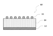
- FIG. 1 is a schematic cross-sectional view showing an example of the configuration of the electrodes according to the present embodiment.
- FIG. 2 is a schematic cross-sectional view of a non-aqueous electrolyte secondary battery which is an example of the embodiment.
- FIG. 1 is a schematic cross-sectional view showing an example of the configuration of the electrode according to the present embodiment.
- the electrode 60 shown in FIG. 1 is an electrode for a non-aqueous electrolyte secondary battery, and is applied to at least one of a positive electrode and a negative electrode of the non-aqueous electrolyte secondary battery.
- the electrode 60 shown in FIG. 1 includes a current collector 62, an active material layer 64 formed on the current collector 62, and an aggregate 66 of filler particles existing in an island shape on the surface of the active material layer 64.
- the surface structure of the electrode 60 is a sea-island structure having a sea region on the surface of the active material layer and an island region of the aggregate 66 of the filler particles.
- the aggregate 66 is a collection of single or a plurality of filler particles.
- the filler particles constituting the aggregate 66 are compound particles containing at least one of phosphorus, silicon, boron, nitrogen, potassium, sodium, and bromine, and are transformed from a solid phase to a liquid phase or thermally decomposed.
- the transformation point is in the range of 180 ° C to 1000 ° C.
- the rise in battery temperature in the nail piercing test is suppressed. This mechanism is not clear enough, but the following can be inferred. Due to the heat generated by the battery during the nail piercing test, that is, the heat generated by the battery when a nail is pierced into the battery to generate an internal short circuit in a simulated manner, the filler particles constituting the aggregate 66 are transformed from a solid phase to a liquid phase. The film flows on the surface of the active material layer 64 or extends on the surface of the active material layer 64 by thermal decomposition to form a film covering the surface of the active material layer 64.
- the film functions as a resistance component, the amount of short-circuit current flowing between the positive and negative electrodes via the nail is suppressed, and as a result, the rise in battery temperature in the nail piercing test is also suppressed.
- the formation of the film after the transformation of the filler particles into the liquid phase depends on the type of the filler particles, but for example, the temperature rise above the melting point of the filler material, the heat fusion reaction, the dehydration condensation reaction, the thermal polymerization reaction, etc. It is due to.
- the electrode for a non-aqueous electrolyte secondary battery according to the present embodiment, an increase in battery resistance is suppressed.
- the aggregate 66 of the filler particles is a material having low lithium ion conductivity, so if it exists in a layer, it inhibits the movement of lithium ions and reduces the battery resistance. Causes a rise.
- it since it is island-shaped in the present embodiment, there is a gap between the aggregates 66, and ions such as lithium ions can easily pass through the gap.
- the lithium ions move smoothly between the positive and negative electrodes as compared with the case where the entire surface of the active material layer 64 is covered with the coating layer of the filler particles without gaps, so that the battery resistance increases. Is thought to be suppressed.
- the filler particles are compound particles containing at least one of phosphorus, silicon, boron, nitrogen, potassium, sodium, and bromine, and have a transformation point of 180 ° C. for transformation from a solid phase to a liquid phase or thermal decomposition. It is not particularly limited as long as it is in the range of about 1000 ° C.
- the filler particles include phosphoric acid compounds, silicic acid compounds, boric acid compounds, melamine compounds, potassium salt compounds, sodium salt compounds and the like.
- Examples of the phosphoric acid compound include phosphoric acid-lithium salt, phosphoric acid-sodium salt, phosphoric acid-potassium salt, phosphoric acid-calcium salt, phosphoric acid-magnesium salt, metal phosphate such as aluminum phosphate, and ammonium polyphosphate. , Condensed phosphates such as sodium tripolyphosphate and melamine polyphosphate, and phosphate esters such as trimethylphosphate and triphenylphosphate.
- the borate compound includes, for example, boric acid-sodium salt, boric acid-potassium salt, boric acid-calcium salt, borate-magnesium salt, aluminum borate, metal borate salt such as melamine borate, trimethyl borate and the like.
- Examples thereof include boric acid ester, boron oxide and condensed borate.
- Examples of the silicic acid compound include silicic acid-sodium salt, silicic acid-potassium salt, silicic acid-calcium salt, silicic acid-magnesium salt, silicic acid-barium salt, silicic acid-metal salt such as manganese salt and the like.
- Examples of the melamine compound include melamine cyanurate, melamine pyrophosphate, ethylene dimelamine, trimethylene dimelamine, tetramethylene dimelamine, hexamethylene dimelamine, and 1,3-hexylene melamine.
- potassium salt compound examples include potassium pyrosulfate (K 2 S 2 O 7 ), potassium citrate monohydrate (C 6 H 5 K 3 O 7 ⁇ H 2 O), potassium carbonate and the like.
- sodium salt compound examples include sodium carbonate and the like.
- Boron oxide, ethylene-1,2-bis (pentabromophenyl), ethylenebistetrabromophthalimide, potassium carbonate, sodium carbonate are preferable.
- the transformation point of the filler particles may be in the range of 180 ° C. to 1000 ° C., but is preferably 250 ° C. so that the filler particles are appropriately transformed from the solid phase to the liquid phase or thermally decomposed by the heat generated by the battery in the nail piercing test. It is in the range of ⁇ 600 ° C.
- the coverage of the aggregate 66 on the surface of the active material layer 64 is preferably 90% or less, more preferably 65% or less, in terms of suppressing an increase in battery resistance. Further, the coverage of the aggregate 66 on the surface of the active material layer 64 is preferably 5% or more from the viewpoint of suppressing an increase in the battery temperature in the nail piercing test. As the coverage increases, the time required to form the cover layer covering the surface of the active material layer 64 during battery heat generation becomes shorter, but the battery resistance increases, so an optimum configuration is required according to the purpose. .. The coverage of the aggregate 66 is calculated as follows.
- the coverage can be determined by elemental mapping of the electrode surface using SEM-EDX (Energy Dispersive X-ray spectroscopy) or the like. For example, it can be obtained by dividing the island region of the aggregate 66 from the sea region on the surface of the active material layer by element mapping and calculating the ratio of the area of the island region to the total area of the island region and the sea region. As for the accuracy of element mapping, if there is an uncovered region of about 2 ⁇ m square, it is possible to distinguish between the sea region and the island region.
- the number of aggregates 66 having an area of 1000 ⁇ m 2 or less is preferably 80% or more, and preferably 90% or more, based on the total number of aggregates 66. As the number of aggregates 66 having an area of 1000 ⁇ m 2 or less increases, the gaps between the aggregates 66, which are paths through which ions such as lithium ions easily pass, increase in a wide range and in a more uniform manner. The increase in resistance can be suppressed.
- the number of aggregates 66 is preferably 100 or more per 1 mm 2 , and more preferably 200 or more. As the number of filler particles constituting the aggregate 66 increases, the filler particles are transformed from a solid phase to a liquid phase or thermally decomposed due to the heat generated by the battery during the nail piercing test to coat the surface of the active material layer 64. Is performed promptly, so that the rise in battery temperature in the nail piercing test can be effectively suppressed.
- the average particle size of the filler particles constituting the aggregate 66 is preferably 0.1 ⁇ m to 20 ⁇ m, and more preferably 0.5 ⁇ m to 3 ⁇ m.
- the average particle size of the filler particles is determined as follows. First, 20 filler particles are randomly selected from the SEM image of the electrode surface. Next, after observing the grain boundaries of the selected 20 filler particles and specifying the outer shape of the filler particles, the area of each of the 20 filler particles is obtained, and the average particle size of the filler particles is calculated from the average value thereof. calculate.
- the aggregate 66 may contain a binder in addition to the filler particles described above. By including the binder, it is possible to improve the binding property between the filler particles and the binding property between the filler particles and the current collector 62.
- the binder is not particularly limited, and examples thereof include polyvinylidene fluoride (PVdF), ethylene dimethacrylate, allyl methacrylate, t-dodecylmerkabutane, ⁇ -methylstyrene dimer, and methacrylic acid.
- Polyvinylidene fluoride (PVdF), ethylene dimethacrylate, allyl methacrylate, t-dodecyl mercaptan, ⁇ -methylstyrene dimer, and methacrylic acid are electrodes of the aggregate 66 when pressure and / or heat is applied. 60 can be adhered to the separator 13. Further, the aggregate 66 may contain compound particles other than the above-mentioned filler particles. Examples of compound particles other than the above-mentioned filler particles include inorganic particles such as alumina, boehmite, and titania.
- the current collector 62 serving as the positive electrode current collector for example, a foil of a metal stable in the potential range of the positive electrode such as aluminum, a film in which the metal is arranged on the surface layer, or the like can be used. .. Further, the active material layer 64 to be the positive electrode active material layer contains a positive electrode active material, and preferably contains a conductive material or a binder.
- Examples of the positive electrode active material include lithium transition metal composite oxides, and specifically, lithium cobaltate, lithium manganate, lithium nickelate, lithium nickel-manganese composite oxide, lithium nickel-cobalt composite oxide and the like are used. Al, Ti, Zr, Nb, B, W, Mg, Mo and the like may be added to these lithium transition metal composite oxides.
- carbon powders such as carbon black, acetylene black, ketjen black, and graphite may be used alone or in combination of two or more.
- binder examples include fluororesins such as polytetrafluoroethylene (PTFE) and polyvinylidene fluoride (PVdF), polyacrylonitrile (PAN), polyimide resins, acrylic resins, and polyolefin resins. These may be used alone or in combination of two or more.
- fluororesins such as polytetrafluoroethylene (PTFE) and polyvinylidene fluoride (PVdF), polyacrylonitrile (PAN), polyimide resins, acrylic resins, and polyolefin resins. These may be used alone or in combination of two or more.
- a positive electrode mixture slurry containing a positive electrode active material, a binder, a conductive material, a solvent, etc. is applied onto the positive electrode current collector, the coating film is dried, and then rolled to form a positive electrode on the positive electrode current collector. Form an active material layer.
- a filler slurry containing filler particles, a binder, a solvent and the like is prepared. Then, the prepared filler slurry is sprayed, dropped, transferred or applied to the positive electrode active material layer and then dried to form an aggregate of filler particles existing in an island shape on the surface of the positive electrode active material layer.
- the solvent contained in the slurry include water, N-methyl-2-pyrrolidone (NMP), ethanol and the like.
- the island-shaped aggregate can be obtained by, for example, adjusting the amount of filler particles and solvent contained in the filler slurry and controlling the spray amount, dropping amount or coating amount of the filler slurry. Further, for example, a masking sheet or the like provided with a plurality of through holes of a predetermined size is arranged on the positive electrode active material layer, and the filler slurry is sprayed, dropped, or applied on the arranged masking sheet. Also, an island-shaped aggregate is obtained.
- the current collector 62 serving as the negative electrode current collector for example, a metal foil stable in the potential range of the negative electrode such as copper, a film in which the metal is arranged on the surface layer, or the like can be used. ..
- the active material layer 64 to be the negative electrode active material layer contains a negative electrode active material, and preferably contains a binder or the like.
- a carbon material capable of storing and releasing lithium ions can be used, and in addition to graphite, non-graphite carbon, easily graphitable carbon, fibrous carbon, coke, carbon black and the like should be used. Can be done. Further, as the non-carbon material, silicon, tin, and alloys and oxides mainly containing these can be used.
- binder examples include fluororesin, PAN, polyimide resin, acrylic resin, polyolefin resin, styrene-butadiene rubber (SBR), nitrile-butadiene rubber (NBR), carboxymethyl cellulose (CMC) or a salt thereof.
- SBR styrene-butadiene rubber
- NBR nitrile-butadiene rubber
- CMC carboxymethyl cellulose
- PAA Polyacrylic acid
- PAA-Na, PAA-K, etc., or a partially neutralized salt polyvinyl alcohol (PVA), and the like. These may be used alone or in combination of two or more.
- a negative electrode mixture slurry containing a negative electrode active material, a binder, a solvent, etc. is applied onto the negative electrode current collector, the coating film is dried, and then rolled to obtain a negative electrode active material layer on the negative electrode current collector. To form.
- a filler slurry containing filler particles, a binder, a solvent, etc. is sprayed, dropped or applied to the negative electrode active material layer, dried, and an island-like filler present on the surface of the negative electrode active material layer. Form an aggregate of particles.
- the method for obtaining the island-shaped aggregate is as described above.
- FIG. 2 is a schematic cross-sectional view of a non-aqueous electrolyte secondary battery which is an example of the embodiment.
- the non-aqueous electrolyte secondary battery 10 shown in FIG. 2 has a wound electrode body 14 in which a positive electrode 11 and a negative electrode 12 are wound via a separator 13, a non-aqueous electrolyte, and above and below the electrode body 14, respectively.
- An arranged insulating plates 18 and 19 and a battery case 15 for accommodating the above members are provided.
- the battery case 15 is composed of a bottomed cylindrical case body 16 and a sealing body 17 that closes an opening of the case body 16.
- the winding type electrode body 14 instead of the winding type electrode body 14, another form of an electrode body such as a laminated type electrode body in which positive electrodes and negative electrodes are alternately laminated via a separator may be applied.
- the battery case 15 include a metal case such as a cylinder, a square, a coin, and a button, and a resin case (so-called laminated type) formed by laminating a resin sheet.
- the case body 16 is, for example, a bottomed cylindrical metal container.
- a gasket 28 is provided between the case body 16 and the sealing body 17 to ensure the airtightness inside the battery.
- the case body 16 has, for example, an overhanging portion 22 that supports the sealing body 17 with a part of the side surface overhanging inward.
- the overhanging portion 22 is preferably formed in an annular shape along the circumferential direction of the case body 16, and the sealing body 17 is supported on the upper surface thereof.
- the sealing body 17 has a structure in which a filter 23, a lower valve body 24, an insulating member 25, an upper valve body 26, and a cap 27 are laminated in this order from the electrode body 14 side.
- Each member constituting the sealing body 17 has, for example, a disk shape or a ring shape, and each member except the insulating member 25 is electrically connected to each other.
- the lower valve body 24 and the upper valve body 26 are connected to each other at the central portion thereof, and an insulating member 25 is interposed between the peripheral portions thereof.
- the lower valve body 24 deforms and breaks so as to push the upper valve body 26 toward the cap 27 side, and the lower valve body 24 and the upper valve body 26 The current path between them is cut off.
- the upper valve body 26 breaks and gas is discharged from the opening of the cap 27.
- the positive electrode lead 20 attached to the positive electrode 11 extends to the sealing body 17 side through the through hole of the insulating plate 18, and the negative electrode lead 21 attached to the negative electrode 12 insulates. It extends to the bottom side of the case body 16 through the outside of the plate 19.
- the positive electrode lead 20 is connected to the lower surface of the filter 23, which is the bottom plate of the sealing body 17, by welding or the like, and the cap 27, which is the top plate of the sealing body 17 electrically connected to the filter 23, serves as the positive electrode terminal.
- the negative electrode lead 21 is connected to the inner surface of the bottom of the case body 16 by welding or the like, and the case body 16 serves as a negative electrode terminal.
- the above-mentioned electrode 60 is applied to at least one of the positive electrode 11 and the negative electrode 12.
- a porous sheet or the like having ion permeability and insulating property is used.
- the porous sheet include a microporous thin film, a woven fabric, and a non-woven fabric.
- olefin resins such as polyethylene and polypropylene, cellulose and the like are suitable.
- the separator 13 may be a laminate having a cellulose fiber layer and a thermoplastic resin fiber layer such as an olefin resin.
- a multilayer separator containing a polyethylene layer and a polypropylene layer may be used, or a separator 13 coated with a material such as an aramid resin or ceramic may be used.
- the non-aqueous electrolyte contains a non-aqueous solvent and an electrolyte salt dissolved in the non-aqueous solvent.
- the non-aqueous solvent for example, esters, ethers, nitriles, amides, and a mixed solvent of two or more of these are used.
- the non-aqueous solvent may contain a halogen substituent in which at least a part of hydrogen in these solvents is substituted with a halogen atom such as fluorine.
- the electrolyte salt for example, a lithium salt such as LiPF 6 is used.
- Example> [Preparation of positive electrode] 100 parts by weight of the positive electrode active material represented by LiNi 0.82 Co 0.15 Al 0.03 O 2 , 1 part by weight of acetylene black (AB), and 1 part by weight of polyvinylidene fluoride (PVdF). After mixing, an appropriate amount of N-methyl-2-pyrrolidone (NMP) was added to prepare a positive electrode mixture slurry. Next, the positive electrode mixture slurry was applied to both sides of the positive electrode current collector made of aluminum foil and dried. This was cut into a predetermined electrode size and rolled using a roller to form positive electrode active material layers on both sides of the positive electrode current collector.
- NMP N-methyl-2-pyrrolidone
- melamine polyphosphate particles 5 parts by weight of melamine polyphosphate particles and 1 part by weight of polyvinylidene fluoride (PVdF) were mixed, and 100 mL of N-methyl-2-pyrrolidone (NMP) was further added to prepare a slurry for filler. 100 mL of the filler slurry was coated on the positive electrode active material layer with a Wet film thickness equivalent to 4 um, and dried. This was used as the positive electrode of Example 1.
- PVdF polyvinylidene fluoride
- NMP N-methyl-2-pyrrolidone
- a negative electrode mixture slurry was prepared by mixing 100 parts by weight of graphite powder, 1 part by weight of carboxymethyl cellulose (CMC), and 1 part by weight of styrene-butadiene rubber (SBR), and further adding an appropriate amount of water. Next, the negative electrode mixture slurry was applied to both sides of the negative electrode current collector made of copper foil and dried. This was cut into a predetermined electrode size and rolled using a roller to form negative electrode active material layers on both sides of the negative electrode current collector.
- CMC carboxymethyl cellulose
- SBR styrene-butadiene rubber
- LiPF 6 Lithium hexafluorophosphate
- EC ethylene carbonate
- EMC ethyl methyl carbonate
- DMC dimethyl carbonate
- Example 2 In the preparation of the filler slurry, except that the amount of polyphosphate melamine particles added was 30 parts by weight and 100 mL of the prepared filler slurry was coated on the positive electrode active material layer with a Wet thickness of 6 um. A non-aqueous electrolyte secondary battery was produced in the same manner as in Example 1. When the surface of the positive electrode of Example 2 was observed by SEM-EDX, it was confirmed that the aggregates of the melamine polyphosphate particles were island-shaped, and the coverage of the aggregates of the melamine polyphosphate particles was 65%. ..
- Example 3 In the preparation of the filler slurry, except that the amount of polyphosphate melamine particles added was 30 parts by weight and 100 mL of the prepared filler slurry was coated on the positive electrode active material layer with a Wet thickness of 10 um. A non-aqueous electrolyte secondary battery was produced in the same manner as in Example 1. When the surface of the positive electrode of Example 3 was observed by SEM-EDX, it was confirmed that the aggregates of the melamine polyphosphate particles were island-shaped, and the coverage of the aggregates of the melamine polyphosphate particles was 90%. ..
- Example 4 was the same as Example 1
- Example 5 was the same as Example 2
- Example 6 was carried out, except that the melamine polyphosphate particles were replaced with ammonium polyphosphate particles.
- a non-aqueous electrolyte secondary battery was produced in the same manner as in Example 3.
- the positive electrode surfaces of Examples 4 to 6 were observed by SEM-EDX, it was confirmed that the aggregates of ammonium polyphosphate particles were island-shaped, and the coverage of the aggregates of ammonium polyphosphate particles was 5%, respectively. , 65%, 90%.
- Example 7 is the same as Example 1 and Example 8 is the same as Example 2 except that the melamine polyphosphate particles are replaced with lithium metaphosphate ((LiPO 3 ) n ) particles in the preparation of the filler slurry.
- Example 9 a non-aqueous electrolyte secondary battery was produced in the same manner as in Example 3.
- the positive electrode surfaces of Examples 7 to 9 were observed by SEM-EDX, it was confirmed that the aggregates of lithium metaphosphate particles were island-shaped, and the coverage of the aggregates of lithium metaphosphate particles was 5%, respectively. , 65%, 90%.
- Example 10 was the same as Example 1 and Example 11 was the same as Example 2 except that the melamine polyphosphate particles were replaced with sodium silicate (Na 2 SiO 3 ) particles in the preparation of the filler slurry.
- Example 12 a non-aqueous electrolyte secondary battery was produced in the same manner as in Example 3.
- the positive electrode surfaces of Examples 10 to 12 were observed by SEM-EDX, it was confirmed that the aggregates of sodium silicate particles were island-shaped, and the coverage of the aggregates of sodium silicate particles was 5%, respectively. , 65%, 90%.
- Example 13 was the same as Example 1 and Example 14 was Example 2 except that the melamine polyphosphate particles were replaced with sodium borate (Na 2 B 4 O 7 ) particles in the preparation of the filler slurry.
- Example 15 a non-aqueous electrolyte secondary battery was produced in the same manner as in Example 3.
- the positive electrode surfaces of Examples 13 to 15 were observed by SEM-EDX, it was confirmed that the aggregates of sodium borate particles were island-shaped, and the coverage of the aggregates of sodium borate particles was 5%, respectively. , 65%, 90%.
- Example 1 A non-aqueous electrolyte secondary battery was produced in the same manner as in Example 1 except that the filler slurry was not used.
- the battery resistance of the non-aqueous electrolyte secondary batteries of Examples 1 to 15 and Comparative Examples 1 to 6 was measured as follows. In a temperature environment of 25 ° C., the non-aqueous electrolyte secondary battery is charged with a constant current of 0.3 C until the battery voltage reaches 4.2 V, and then charged with a constant voltage until the current value reaches 0.05 C. Then, it was discharged with a constant current of 0.3C to set the SOC to 50%. Next, the voltage values when the discharge currents of 0A, 0.1A, 0.5A, and 1.0A were applied for 10 seconds were acquired. DC-IR was calculated from the absolute value of the slope when the voltage value after 10 seconds for each discharge current value was linearly approximated by the least squares method, and this value is summarized in Table 1 as the battery resistance.
- Examples 1 to 15 in which an aggregate of filler particles is present on the surface of the positive electrode active material layer in an island shape, there is no filler particle on the surface of the positive electrode active material layer. Therefore, the battery temperature after the nail piercing test was low.
- the coverage of the aggregate of the filler particles is 100% as in Comparative Examples 2 to 6, the battery resistance is remarkably increased as compared with Comparative Example 1.
- the increase in battery resistance was suppressed as compared with Comparative Examples 2 to 6. That is, in Examples 1 to 15, the heat generation of the battery in the nail piercing test could be suppressed while suppressing the increase in the battery resistance.
- Examples 16 to 30 are non-aqueous as in Examples 1 to 15, except that coating the filler slurry on the positive electrode active material layer is replaced with coating on the negative electrode active material layer, respectively.
- An electrolyte secondary battery was manufactured.
- Comparative Examples 7 to 10 are non-aqueous in the same manner as in Comparative Examples 2 to 6, except that coating the filler slurry on the positive electrode active material layer is replaced with coating on the negative electrode active material layer. An electrolyte secondary battery was manufactured.
- Table 2 summarizes the coverage of the aggregates of the filler particles in Examples 16 to 30 and Comparative Examples 7 to 10. Further, in the non-aqueous electrolyte secondary batteries of Examples 16 to 30 and Comparative Examples 7 to 10, the above-mentioned nail piercing test and battery resistance measurement were performed, and the results are summarized in Table 2.
- Examples 31-40> In the preparation of the filler slurry, the polyphosphate melamine particles were replaced with tripolyphosphate sodium particles in Example 31, potassium phosphate (KH 2 PO 4 ) particles in Example 32, and melamine cyanurate in Example 33. , Example 34 replaced with potassium pyrosulfate (K 2 S 2 O 7 ) particles, Example 35 replaced with boron oxide (B 2 O 3 ) particles, and Example 36 replaced with ethylene-1,2-bis (pentabromo).
- Example 37 ethylene bistetrabromophthalimide particles were used, in Example 38, potassium citrate (C 6 H 5 K 3 O 7 ) particles were used, and in Example 39, potassium carbonate (K 2 CO) was used.
- Example 38 potassium citrate (C 6 H 5 K 3 O 7 ) particles were used, and in Example 39, potassium carbonate (K 2 CO) was used.
- K 2 CO potassium carbonate
- Table 3 summarizes the coverage of the aggregate of filler particles in Examples 31 to 40. Further, in the non-aqueous electrolyte secondary batteries of Examples 31 to 40, the above-mentioned nail piercing test and battery resistance measurement were performed, and the results are summarized in Table 3.
- Example 31 to 40 the battery temperature after the nail piercing test was lower than that in Comparative Example 1 in which there were no filler particles on the surface of the positive electrode active material layer. Further, although the battery resistance was higher than that of Comparative Example 1, it was about the same as that of Example 1. That is, it can be said that Examples 31 to 40 were also able to suppress the heat generation of the battery in the nail piercing test while suppressing the increase in battery resistance.
- Non-aqueous electrolyte secondary battery 11 Positive electrode 12 Negative electrode 13 Separator 14 Electrode body 15 Battery case 16 Case body 17 Sealing body 18, 19 Insulating plate 20 Positive lead 21 Negative electrode lead 22 Overhanging part 23 Filter 24 Lower valve body 25 Insulating member 26 Valve body 27 Cap 28 Gasket 60 Electrode 62 Current collector 64 Active material layer 66 Aggregate
Landscapes
- Chemical & Material Sciences (AREA)
- Chemical Kinetics & Catalysis (AREA)
- Electrochemistry (AREA)
- General Chemical & Material Sciences (AREA)
- Engineering & Computer Science (AREA)
- Materials Engineering (AREA)
- Battery Electrode And Active Subsutance (AREA)
- Secondary Cells (AREA)
Priority Applications (4)
| Application Number | Priority Date | Filing Date | Title |
|---|---|---|---|
| CN202080089406.5A CN114846644B (zh) | 2019-12-26 | 2020-10-29 | 非水电解质二次电池用电极及非水电解质二次电池 |
| EP20906062.3A EP4084117B1 (en) | 2019-12-26 | 2020-10-29 | Electrode for nonaqueous electrolyte secondary battery and nonaqueous electrolyte secondary battery |
| JP2021566869A JP7634181B2 (ja) | 2019-12-26 | 2020-10-29 | 非水電解質二次電池用電極及び非水電解質二次電池 |
| US17/788,141 US12494487B2 (en) | 2019-12-26 | 2020-10-29 | Electrode for nonaqueous electrolyte secondary battery and nonaqueous electrolyte secondary battery |
Applications Claiming Priority (2)
| Application Number | Priority Date | Filing Date | Title |
|---|---|---|---|
| JP2019236845 | 2019-12-26 | ||
| JP2019-236845 | 2019-12-26 |
Publications (1)
| Publication Number | Publication Date |
|---|---|
| WO2021131313A1 true WO2021131313A1 (ja) | 2021-07-01 |
Family
ID=76574057
Family Applications (1)
| Application Number | Title | Priority Date | Filing Date |
|---|---|---|---|
| PCT/JP2020/040605 Ceased WO2021131313A1 (ja) | 2019-12-26 | 2020-10-29 | 非水電解質二次電池用電極及び非水電解質二次電池 |
Country Status (5)
| Country | Link |
|---|---|
| US (1) | US12494487B2 (https=) |
| EP (1) | EP4084117B1 (https=) |
| JP (1) | JP7634181B2 (https=) |
| CN (1) | CN114846644B (https=) |
| WO (1) | WO2021131313A1 (https=) |
Cited By (2)
| Publication number | Priority date | Publication date | Assignee | Title |
|---|---|---|---|---|
| JP7444366B1 (ja) | 2023-03-27 | 2024-03-06 | 地方独立行政法人大阪産業技術研究所 | 非水電解質二次電池の電極及びその製造方法 |
| EP4353368A1 (en) * | 2022-09-30 | 2024-04-17 | FUJIFILM Corporation | Film forming method |
Citations (8)
| Publication number | Priority date | Publication date | Assignee | Title |
|---|---|---|---|---|
| JP2005276503A (ja) * | 2004-03-23 | 2005-10-06 | Mitsubishi Electric Corp | 電池用セパレータ及びそれを用いた電池 |
| JP2009164014A (ja) * | 2008-01-08 | 2009-07-23 | Mitsui Mining & Smelting Co Ltd | 非水電解液二次電池用負極 |
| JP2010192365A (ja) * | 2009-02-20 | 2010-09-02 | Toyota Motor Corp | リチウムイオン電池 |
| JP2010238464A (ja) * | 2009-03-31 | 2010-10-21 | Sanyo Electric Co Ltd | リチウム二次電池 |
| JP2013054909A (ja) * | 2011-09-05 | 2013-03-21 | Hitachi Ltd | リチウムイオン二次電池 |
| JP2015138598A (ja) * | 2014-01-20 | 2015-07-30 | ソニー株式会社 | 電池、電池パック、電子機器、電動車両、蓄電装置および電力システム |
| JP2017534138A (ja) | 2015-10-14 | 2017-11-16 | 中航▲里電▼(洛▲陽▼)有限公司China Aviation Lithium Battery Co., Ltd. | リチウムイオン電池用複合極板及びその製造方法並びにリチウムイオン電池 |
| JP6249399B2 (ja) | 2013-12-19 | 2017-12-20 | 株式会社村田製作所 | リチウムイオン二次電池用電極、リチウムイオン二次電池、電池パック、電動車両、電力貯蔵システム、電動工具および電子機器 |
Family Cites Families (9)
| Publication number | Priority date | Publication date | Assignee | Title |
|---|---|---|---|---|
| JP4766348B2 (ja) * | 2008-10-10 | 2011-09-07 | トヨタ自動車株式会社 | リチウム二次電池およびその製造方法 |
| JP2014150034A (ja) * | 2013-02-04 | 2014-08-21 | Asahi Glass Co Ltd | 蓄電デバイス用電極および蓄電デバイス |
| JP6474548B2 (ja) | 2014-01-16 | 2019-02-27 | 信越化学工業株式会社 | 非水電解質二次電池用負極材及び負極活物質粒子の製造方法 |
| KR102086887B1 (ko) | 2014-01-20 | 2020-03-09 | 가부시키가이샤 무라타 세이사쿠쇼 | 전지, 전지 팩, 전자 기기, 전동 차량, 축전 장치 및 전력 시스템 |
| JP6489009B2 (ja) * | 2014-02-24 | 2019-03-27 | 東レ株式会社 | ガス拡散電極基材 |
| DE112015004498T5 (de) * | 2014-09-30 | 2017-06-29 | Gs Yuasa International Ltd. | Negative elektrode für eine nichtwässrige elektrolyt-energiespeichervorrichtung, nichtwässrige elektrolyt-energiespeichervorrichtung, energiespeicherapparat |
| KR20170117649A (ko) * | 2016-04-14 | 2017-10-24 | 주식회사 엘지화학 | 리튬 전극용 보호막, 이를 포함하는 리튬 전극 및 리튬 이차전지 |
| JP6918638B2 (ja) * | 2017-08-23 | 2021-08-11 | 三洋電機株式会社 | 非水電解質二次電池 |
| WO2020080246A1 (ja) * | 2018-10-18 | 2020-04-23 | 株式会社村田製作所 | リチウムイオン二次電池用負極およびリチウムイオン二次電池 |
-
2020
- 2020-10-29 US US17/788,141 patent/US12494487B2/en active Active
- 2020-10-29 JP JP2021566869A patent/JP7634181B2/ja active Active
- 2020-10-29 EP EP20906062.3A patent/EP4084117B1/en active Active
- 2020-10-29 CN CN202080089406.5A patent/CN114846644B/zh active Active
- 2020-10-29 WO PCT/JP2020/040605 patent/WO2021131313A1/ja not_active Ceased
Patent Citations (8)
| Publication number | Priority date | Publication date | Assignee | Title |
|---|---|---|---|---|
| JP2005276503A (ja) * | 2004-03-23 | 2005-10-06 | Mitsubishi Electric Corp | 電池用セパレータ及びそれを用いた電池 |
| JP2009164014A (ja) * | 2008-01-08 | 2009-07-23 | Mitsui Mining & Smelting Co Ltd | 非水電解液二次電池用負極 |
| JP2010192365A (ja) * | 2009-02-20 | 2010-09-02 | Toyota Motor Corp | リチウムイオン電池 |
| JP2010238464A (ja) * | 2009-03-31 | 2010-10-21 | Sanyo Electric Co Ltd | リチウム二次電池 |
| JP2013054909A (ja) * | 2011-09-05 | 2013-03-21 | Hitachi Ltd | リチウムイオン二次電池 |
| JP6249399B2 (ja) | 2013-12-19 | 2017-12-20 | 株式会社村田製作所 | リチウムイオン二次電池用電極、リチウムイオン二次電池、電池パック、電動車両、電力貯蔵システム、電動工具および電子機器 |
| JP2015138598A (ja) * | 2014-01-20 | 2015-07-30 | ソニー株式会社 | 電池、電池パック、電子機器、電動車両、蓄電装置および電力システム |
| JP2017534138A (ja) | 2015-10-14 | 2017-11-16 | 中航▲里電▼(洛▲陽▼)有限公司China Aviation Lithium Battery Co., Ltd. | リチウムイオン電池用複合極板及びその製造方法並びにリチウムイオン電池 |
Non-Patent Citations (1)
| Title |
|---|
| See also references of EP4084117A4 |
Cited By (3)
| Publication number | Priority date | Publication date | Assignee | Title |
|---|---|---|---|---|
| EP4353368A1 (en) * | 2022-09-30 | 2024-04-17 | FUJIFILM Corporation | Film forming method |
| JP7444366B1 (ja) | 2023-03-27 | 2024-03-06 | 地方独立行政法人大阪産業技術研究所 | 非水電解質二次電池の電極及びその製造方法 |
| JP2024139287A (ja) * | 2023-03-27 | 2024-10-09 | 地方独立行政法人大阪産業技術研究所 | 非水電解質二次電池の電極及びその製造方法 |
Also Published As
| Publication number | Publication date |
|---|---|
| US20230029595A1 (en) | 2023-02-02 |
| US12494487B2 (en) | 2025-12-09 |
| EP4084117B1 (en) | 2025-01-08 |
| CN114846644B (zh) | 2025-06-27 |
| EP4084117A1 (en) | 2022-11-02 |
| JPWO2021131313A1 (https=) | 2021-07-01 |
| CN114846644A (zh) | 2022-08-02 |
| JP7634181B2 (ja) | 2025-02-21 |
| EP4084117A4 (en) | 2023-12-27 |
Similar Documents
| Publication | Publication Date | Title |
|---|---|---|
| JP6777388B2 (ja) | 非水電解質二次電池 | |
| JP7373727B2 (ja) | 非水電解質二次電池 | |
| US10347946B2 (en) | Non-aqueous electrolyte secondary battery, electrode body used therefor, and method of manufacturing the electrode body | |
| US20150207134A1 (en) | Secondary battery | |
| WO2019065062A1 (ja) | 非水電解質二次電池 | |
| WO2019107067A1 (ja) | 非水電解質二次電池 | |
| JP7634181B2 (ja) | 非水電解質二次電池用電極及び非水電解質二次電池 | |
| JP7584105B2 (ja) | 非水電解質二次電池用セパレータ及び非水電解質二次電池 | |
| WO2019131193A1 (ja) | 非水電解質二次電池 | |
| JP7336680B2 (ja) | 二次電池 | |
| JP6008188B2 (ja) | 非水電解液二次電池 | |
| WO2019146413A1 (ja) | 非水電解質二次電池用正極及び非水電解質二次電池 | |
| JP2016186886A (ja) | 蓄電素子 | |
| JP7466200B2 (ja) | 正極及び二次電池 | |
| CN114868277B (zh) | 非水电解质二次电池用电极及非水电解质二次电池 | |
| JP7182288B2 (ja) | 非水電解質二次電池用正極及び非水電解質二次電池 | |
| WO2025028498A1 (ja) | 非水電解質二次電池用正極及び非水電解質二次電池 | |
| JPWO2020003605A1 (ja) | 電極構造体及び非水電解質二次電池 |
Legal Events
| Date | Code | Title | Description |
|---|---|---|---|
| 121 | Ep: the epo has been informed by wipo that ep was designated in this application |
Ref document number: 20906062 Country of ref document: EP Kind code of ref document: A1 |
|
| WWE | Wipo information: entry into national phase |
Ref document number: 2021566869 Country of ref document: JP |
|
| NENP | Non-entry into the national phase |
Ref country code: DE |
|
| ENP | Entry into the national phase |
Ref document number: 2020906062 Country of ref document: EP Effective date: 20220726 |
|
| WWG | Wipo information: grant in national office |
Ref document number: 202080089406.5 Country of ref document: CN |
|
| WWG | Wipo information: grant in national office |
Ref document number: 17788141 Country of ref document: US |