WO2021131219A1 - 太陽電池パネル製造装置、太陽電池パネル製造方法及び太陽電池パネル - Google Patents
太陽電池パネル製造装置、太陽電池パネル製造方法及び太陽電池パネル Download PDFInfo
- Publication number
- WO2021131219A1 WO2021131219A1 PCT/JP2020/037685 JP2020037685W WO2021131219A1 WO 2021131219 A1 WO2021131219 A1 WO 2021131219A1 JP 2020037685 W JP2020037685 W JP 2020037685W WO 2021131219 A1 WO2021131219 A1 WO 2021131219A1
- Authority
- WO
- WIPO (PCT)
- Prior art keywords
- solar cell
- adhesive
- substrate
- cell panel
- panel manufacturing
- Prior art date
- Legal status (The legal status is an assumption and is not a legal conclusion. Google has not performed a legal analysis and makes no representation as to the accuracy of the status listed.)
- Ceased
Links
Images







Classifications
-
- H—ELECTRICITY
- H10—SEMICONDUCTOR DEVICES; ELECTRIC SOLID-STATE DEVICES NOT OTHERWISE PROVIDED FOR
- H10F—INORGANIC SEMICONDUCTOR DEVICES SENSITIVE TO INFRARED RADIATION, LIGHT, ELECTROMAGNETIC RADIATION OF SHORTER WAVELENGTH OR CORPUSCULAR RADIATION
- H10F19/00—Integrated devices, or assemblies of multiple devices, comprising at least one photovoltaic cell covered by group H10F10/00, e.g. photovoltaic modules
- H10F19/80—Encapsulations or containers for integrated devices, or assemblies of multiple devices, having photovoltaic cells
-
- H—ELECTRICITY
- H10—SEMICONDUCTOR DEVICES; ELECTRIC SOLID-STATE DEVICES NOT OTHERWISE PROVIDED FOR
- H10F—INORGANIC SEMICONDUCTOR DEVICES SENSITIVE TO INFRARED RADIATION, LIGHT, ELECTROMAGNETIC RADIATION OF SHORTER WAVELENGTH OR CORPUSCULAR RADIATION
- H10F71/00—Manufacture or treatment of devices covered by this subclass
- H10F71/137—Batch treatment of the devices
- H10F71/1375—Apparatus for automatic interconnection of photovoltaic cells in a module
-
- H—ELECTRICITY
- H10—SEMICONDUCTOR DEVICES; ELECTRIC SOLID-STATE DEVICES NOT OTHERWISE PROVIDED FOR
- H10F—INORGANIC SEMICONDUCTOR DEVICES SENSITIVE TO INFRARED RADIATION, LIGHT, ELECTROMAGNETIC RADIATION OF SHORTER WAVELENGTH OR CORPUSCULAR RADIATION
- H10F19/00—Integrated devices, or assemblies of multiple devices, comprising at least one photovoltaic cell covered by group H10F10/00, e.g. photovoltaic modules
- H10F19/80—Encapsulations or containers for integrated devices, or assemblies of multiple devices, having photovoltaic cells
- H10F19/85—Protective back sheets
-
- H—ELECTRICITY
- H10—SEMICONDUCTOR DEVICES; ELECTRIC SOLID-STATE DEVICES NOT OTHERWISE PROVIDED FOR
- H10F—INORGANIC SEMICONDUCTOR DEVICES SENSITIVE TO INFRARED RADIATION, LIGHT, ELECTROMAGNETIC RADIATION OF SHORTER WAVELENGTH OR CORPUSCULAR RADIATION
- H10F19/00—Integrated devices, or assemblies of multiple devices, comprising at least one photovoltaic cell covered by group H10F10/00, e.g. photovoltaic modules
- H10F19/90—Structures for connecting between photovoltaic cells, e.g. interconnections or insulating spacers
- H10F19/902—Structures for connecting between photovoltaic cells, e.g. interconnections or insulating spacers for series or parallel connection of photovoltaic cells
-
- H—ELECTRICITY
- H10—SEMICONDUCTOR DEVICES; ELECTRIC SOLID-STATE DEVICES NOT OTHERWISE PROVIDED FOR
- H10F—INORGANIC SEMICONDUCTOR DEVICES SENSITIVE TO INFRARED RADIATION, LIGHT, ELECTROMAGNETIC RADIATION OF SHORTER WAVELENGTH OR CORPUSCULAR RADIATION
- H10F71/00—Manufacture or treatment of devices covered by this subclass
-
- Y—GENERAL TAGGING OF NEW TECHNOLOGICAL DEVELOPMENTS; GENERAL TAGGING OF CROSS-SECTIONAL TECHNOLOGIES SPANNING OVER SEVERAL SECTIONS OF THE IPC; TECHNICAL SUBJECTS COVERED BY FORMER USPC CROSS-REFERENCE ART COLLECTIONS [XRACs] AND DIGESTS
- Y02—TECHNOLOGIES OR APPLICATIONS FOR MITIGATION OR ADAPTATION AGAINST CLIMATE CHANGE
- Y02E—REDUCTION OF GREENHOUSE GAS [GHG] EMISSIONS, RELATED TO ENERGY GENERATION, TRANSMISSION OR DISTRIBUTION
- Y02E10/00—Energy generation through renewable energy sources
- Y02E10/50—Photovoltaic [PV] energy
-
- Y—GENERAL TAGGING OF NEW TECHNOLOGICAL DEVELOPMENTS; GENERAL TAGGING OF CROSS-SECTIONAL TECHNOLOGIES SPANNING OVER SEVERAL SECTIONS OF THE IPC; TECHNICAL SUBJECTS COVERED BY FORMER USPC CROSS-REFERENCE ART COLLECTIONS [XRACs] AND DIGESTS
- Y02—TECHNOLOGIES OR APPLICATIONS FOR MITIGATION OR ADAPTATION AGAINST CLIMATE CHANGE
- Y02P—CLIMATE CHANGE MITIGATION TECHNOLOGIES IN THE PRODUCTION OR PROCESSING OF GOODS
- Y02P70/00—Climate change mitigation technologies in the production process for final industrial or consumer products
- Y02P70/50—Manufacturing or production processes characterised by the final manufactured product
Definitions
- This disclosure relates to a solar cell panel manufacturing apparatus, a solar cell panel manufacturing method, and a solar cell panel.
- Patent Document 1 describes a bonding method for adhering a plurality of solar cells to a honeycomb panel by pressurizing the solar cell through a cushion and spreading an adhesive arranged between the solar cell and the honeycomb panel.
- a solar cell panel manufactured by using the bonding method is known.
- Patent Document 2 discloses a method of adhering a solar cell and a cover glass.
- the bonding method of Patent Document 2 pressurizes the cover glass positioned by the positioning pin and partially heats the surface of the cover glass to partially cure the adhesive between the solar cell and the cover glass. Let me. Then, the solar cell and the cover glass bonded by the partially cured adhesive are placed in an oven to cure the remaining adhesive.
- a positioning pin must be provided on the honeycomb panel. Therefore, it takes time to partially bond the plurality of solar cells and the honeycomb panel, and the manufacturing efficiency of the solar cell panel is lowered.
- the present disclosure has been made in view of the above circumstances, and an object of the present disclosure is to provide a solar cell panel manufacturing apparatus, a solar cell panel manufacturing method, and a solar cell panel having high manufacturing efficiency.
- the solar cell panel manufacturing apparatus includes a stage, a pressure plate, and a cured portion.
- a substrate is placed on the stage.
- the pressure plate applies pressure to the adhesive to spread the adhesive through a solar cell located in a preset position on the adhesive applied to the substrate, and the position of the solar cell with respect to the substrate.
- the cured portion is a part of the adhesive spread between the substrate and the solar cell in a state where the adhesive is pressed by the pressure plate and the solar cell is held in position with respect to the substrate by the pressure plate. Only cure.
- the pressure plate spreads the adhesive, and the cured portion cures only a part of the expanded adhesive, so that the manufacturing efficiency can be increased.
- FIG. 1 A perspective view showing a solar cell panel according to the first embodiment.
- FIG. 1 A cross-sectional view of the solar cell panel shown in FIG. 1 taken along the line II-II.
- Block diagram of the control unit of the solar cell panel manufacturing apparatus according to the first embodiment Flow chart of the solar cell panel manufacturing method according to the first embodiment
- the figure for demonstrating the 4th process of the solar cell panel manufacturing method which concerns on Embodiment 1. The figure for demonstrating the 5th process of the solar cell panel manufacturing method which concerns on Embodiment 1.
- Perspective view of the head of the solar cell panel manufacturing apparatus according to the second embodiment Perspective view of the head of the solar cell panel manufacturing apparatus according to the second embodiment.
- the figure for demonstrating the 4th process of the solar cell panel manufacturing method which concerns on Embodiment 3. The figure for demonstrating the cured part of the adhesive layer in the 4th step of the solar cell panel manufacturing method which concerns on Embodiment 3.
- the figure for demonstrating the adhesive of the solar cell panel which concerns on Embodiment 7.
- the solar cell panel 100 manufactured by the solar cell panel manufacturing apparatus 200 and the solar cell panel manufacturing method according to the present embodiment will be described with reference to FIGS. 1 and 2.
- the solar cell panel 100 includes a substrate 20, a plurality of solar cells 10 arranged on the substrate 20 and adhered to the substrate 20, and wiring 11 for connecting the solar cells 10 to each other.
- the solar cell panel 100 is mounted on an artificial satellite, for example.
- the solar cell panel 100 may be mounted on an artificial satellite in combination with a frame or panel using a carbon fiber composite material, an extending reinforcing member, an aluminum housing, or the like.
- the solar cell 10 is, for example, a single crystal silicon-based solar cell.
- the solar cell 10 is adhered to one main surface 22 of the substrate 20 with an adhesive 30 as shown in FIG. 2 in a cross-sectional view taken along line II-II.
- the light receiving surface of the solar cell 10 may be covered with a cover glass.
- the wiring 11 appropriately connects the plurality of solar cells 10 and the electrodes.
- the substrate 20 is formed of a flexible and windable sheet, a honeycomb panel, or the like.
- the honeycomb panel includes, for example, an aluminum honeycomb core and a plate made of a carbon fiber composite material provided on both sides of the honeycomb core.
- the flexible and windable sheet is, for example, a polyimide sheet.
- the adhesive 30 is, for example, a thermosetting adhesive that cures when heated to a curing temperature or higher.
- the adhesive 30 spreads in a thin film between the solar cell 10 and the substrate 20 and adheres the two.
- the solar cell panel manufacturing apparatus 200 includes a stage 210 on which the substrate 20 is placed, a transfer mechanism 220 for moving the head 300 described later, a load meter 230, a transfer mechanism 220, and a head 300.
- a connecting portion 240 for connecting is provided.
- the solar cell panel manufacturing apparatus 200 has a head 300 for arranging the solar cell 10 on the adhesive 30 applied to the substrate 20 and applying pressure to the adhesive 30 to spread the adhesive 30, and the spread adhesive. It includes a heating unit 350 that cures only a part of the agent 30, and a control unit 400 that controls each unit.
- the upward direction in FIG. 3 is the + Z direction
- the downward direction that is, the vertical direction is the -Z direction
- the left and right directions are the -X direction and the + X direction
- the paper surface depth direction and the paper surface The front direction will be described as the ⁇ Y direction and the + Y direction.
- the stage 210 is a flat metal plate.
- the substrate 20 of the solar cell panel 100 is placed on the surface 210a of the stage 210.
- the substrate 20 is fixed to the surface 210a of the stage 210 by a jig (not shown).
- the adhesive 30 is applied to the planned arrangement position of the solar cell 10 on the main surface 22 of the substrate 20.
- the surface 210a on which the substrate 20 of the stage 210 is placed may be formed of resin.
- the surface 210a is preferably formed of a resin having a lower thermal conductivity than that of metal.
- the transport mechanism 220 moves the head 300 in the ⁇ X direction, the ⁇ Y direction, and the ⁇ Z direction, respectively.
- the transport mechanism 220 includes an X-direction drive unit 222, a Y-direction drive unit 224, and a Z-direction drive unit 226 that are orthogonal to each other.
- the Z-direction drive unit 226 and the head 300 are connected by a connecting unit 240.
- the X-direction drive unit 222 is provided in the Y-direction drive unit 224, and moves the head 300 in each of the ⁇ X directions.
- the Y-direction drive unit 224 is provided on the surface 210a of the stage 210, and by moving the X-direction drive unit 222 in each of the ⁇ Y directions, the head 300 is moved in each of the ⁇ Y directions.
- the Z-direction drive unit 226 is provided in the X-direction drive unit 222, and moves the head 300 in each of the ⁇ Z directions.
- the X-direction drive unit 222, the Y-direction drive unit 224, and the Z-direction drive unit 226 each include a motor, a ball screw, a slider, and the like (not shown).
- the load meter 230 is provided between the Z-direction drive unit 226 and the connecting unit 240.
- the load meter 230 measures the pressure applied to the adhesive 30.
- the load cell 230 includes, for example, a compression type load cell.
- the connecting portion 240 includes, for example, a metal plate, and connects the end portion of the Z-direction drive portion 226 and the head 300 via a load meter 230.
- the head 300 has a function of adsorbing the solar cell 10 and a function of pressurizing the solar cell 10. As shown in FIG. 4, the head 300 includes a suction portion 310 that sucks the solar cell 10, a pressure plate 320 that applies pressure to the adhesive 30 via the suction solar cell 10, and a support portion 330. And.
- the suction unit 310 sucks the solar cell 10 via the pressure plate 320.
- the suction unit 310 includes, for example, a suction plate 311 and a vacuum pipe 312.
- the suction plate 311 is formed in a plate shape. One end of the suction plate 311 is open to the lower surface. A plurality of intake passages are formed at the other end of the suction plate 311. The intake passage is connected to the vacuum pipe 312. The vacuum pipe 312 is connected to the vacuum pump via a valve (not shown). The suction unit 310 sucks the solar cell 10 by sucking air from the lower surface of the suction plate 311 via the vacuum pipe 312 and the intake path.
- the pressure plate 320 presses the solar cell 10 from the upper surface of the solar cell 10. Further, the pressure plate 320 holds the position of the solar cell 10 with respect to the substrate 20.
- the pressure plate 320 includes a flat plate arranged on the lower surface of the suction plate 311.
- the pressure plate 320 is formed with an intake passage that communicates with the intake passage of the suction plate 311.
- the intake passage is open on the lower surface of the pressure plate 320.
- the pressure plate 320 is preferably formed of an elastic material in order to imitate the shape.
- the elastic material is, for example, ethylene propylene diene rubber (EPDM).
- the suction plate 311 and the pressure plate 320 may be integrally formed by providing the pressure plate 320 with a suction hole for vacuum suction.
- the support portion 330 fixes the suction plate 311 to the connecting portion 240.
- the heating unit 350 partially heats and cures the layer of the adhesive 30.
- the heating unit 350 includes a heat transfer unit 351 formed of a material having high thermal conductivity, a heater 352 that generates heat, a temperature sensor 353 that measures the temperature of the heat transfer unit 351, a support unit 354, and a heat insulating material 355. , Equipped with.
- the heat transfer portion 351 is formed of a material having high thermal conductivity. Aluminum is an example of a material having high thermal conductivity.
- the lower end of the heat transfer portion 351 is exposed in the openings formed in the suction plate 311 and the pressure plate 320.
- the lower surface of the heat transfer portion 351 is formed flat so as to be able to come into contact with the adsorbed solar cell 10.
- the heater 352 is, for example, a ceramic heater.
- the heater 352 is fixed to the heat transfer unit 351.
- the heater 352 generates heat when energized.
- the temperature sensor 353 includes a thermistor, wiring, and the like.
- the temperature sensor 353 is fixed to the heat transfer unit 351.
- the temperature sensor 353 measures the temperature of the heat transfer unit 351 and feeds back the measured temperature to the control unit 400.
- the support unit 354 supports the heat transfer unit 351. Further, the support portion 354 fixes the heat transfer portion 351 to the support portion 330 of the head 300. It is desirable that the support portion 354 movably support the heat transfer portion 351 along the Z direction in which the pressure plate 320 applies pressure to the adhesive 30. As a result, the heat transfer unit 351 can move relatively in the Z direction according to the height of the surface of the solar cell 10, and the heat transfer unit 351 can maintain the state of being in contact with the solar cell 10. Further, it is desirable that the support portion 354 supports the heat transfer portion 351 so as to be tiltable according to the tilt of the surface of the solar cell 10.
- the heat transfer unit 351 can be tilted following the inclination of the surface of the solar cell 10, and the heat transfer unit 351 can be maintained in contact with the solar cell 10.
- the force with which the heat transfer unit 351 abuts on the solar cell 10, that is, the force with which the heating unit 350 abuts on the solar cell 10, is the weight of the heating unit 350, the weight provided on the heating unit 350, and the support of the head 300. It can be controlled by a spring or the like provided on the portion 330.
- the heat insulating material 355 is arranged between the heat transfer portion 351 and the support portion 354.
- the heat insulating material 355 fixes the heat transfer portion 351 to the support portion 330 while suppressing the heat of the heater 352 from being transferred to other parts of the head 300.
- the heat insulating material 355 is, for example, a heat insulating plate.
- the heat insulating plate contains, for example, glass fiber as a substrate.
- the control unit 400 shown in FIG. 3 controls the entire operation of fixing the solar cell 10 to the substrate 20.
- the control unit 400 functions as a CPU (Central Processing Unit) 401 for executing the program, a ROM (Read Only Memory) 402 for storing the program, and a work rear of the CPU 401. It is provided with a RAM (Randam Access Memory) 403 to be used, and an input / output interface 404 that communicates with an external device.
- a CPU Central Processing Unit
- ROM Read Only Memory
- the CPU 401 executes the operation program stored in the ROM 402 with the RAM 403 as a work area, and executes the method for manufacturing the solar cell panel 100, which will be described later with reference to FIG. Specifically, the CPU 401 controls the suction drive unit 313 including the valve, the vacuum pump, and the like described above to suck the solar cell 10 on the head 300. Further, the CPU 401 controls the above-mentioned transport mechanism 220, and the head 300 transports the solar cell 10 in the ⁇ X, ⁇ Y, and ⁇ Z directions. Further, the CPU 401 controls the Z-direction drive unit 226 and presses the solar cell 10 in the ⁇ Z direction by the pressure plate 320 of the head 300.
- the CPU 401 monitors the load applied to the solar cell 10 based on the measured value of the load meter 230. When the load applied to the solar cell 10 exceeds the reference level, the CPU 401 controls the Z-direction drive unit 226 to move the head 300 in the + Z direction. As a result, it is possible to prevent an excessive load from being applied to the solar cell 10. Further, the CPU 401 controls the heater 352 to heat the heat transfer unit 351 to the target temperature, thereby partially heating and curing the layer of the adhesive 30 between the substrate 20 and the solar cell 10. The CPU 401 sets the target temperature of the heat transfer unit 351 to be about 5 ° C. to 10 ° C. higher than the curing temperature of the adhesive 30 in order to raise the temperature of the adhesive 30 to cure it.
- the temperature of the pressure plate 320 is set to about 60 ° C. so that the viscosity of the adhesive 30 does not increase even during continuous operation.
- the CPU 401 feedback-controls the calorific value of the heater 352 based on the measured temperature of the temperature sensor 353. Further, the CPU 401 has a built-in timer.
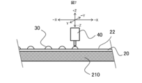
- the adhesive 30 is applied onto the main surface 22 of the substrate 20 by a coating portion 40 such as a despenser or a brush (first step: step S1).
- the coating pattern of the adhesive 30 is preferably point coating, radial line coating, or the like in order to prevent air bubbles from being entrained when pressure is applied in the third step described later.
- a controlled amount of the adhesive 30 is applied to the controlled position.
- the substrate 20 coated with the adhesive 30 is placed on the surface 210a of the stage 210 and fixed.
- the substrate 20 coated with the adhesive 30 is not turned upside down. This makes it possible to prevent the adhesive 30 from dripping and breaking the coating pattern of the adhesive 30.
- the CPU 401 controls the suction drive unit 313 to suck the solar cell 10 with the head 300 as shown in FIG.
- the CPU 401 controls the transport mechanism 220 to transport the adsorbed solar cell 10 to the transport mechanism 220 and arranges the solar cell 10 on the substrate 20 immediately above the planned arrangement position (second).
- the position of the solar cell 10 with respect to the substrate 20 may be determined by controlling the position of the head 300 with respect to the stage 210 by a pattern recognition technique.
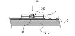
- the CPU 401 controls the Z-direction drive unit 226 and lowers the head 300 as shown in FIG. 9 to spread the adhesive 30 between the solar cell 10 and the substrate 20 and bond them.
- the agent 30 is layered (third step: pressurizing step: step S3).
- step S3 pressurizing step: step S3
- the target value of the pressing force is set after verifying in advance the force with which the adhesive 30 spreads sufficiently. Further, the set time until the adhesive 30 is sufficiently spread is verified and determined in advance.
- the CPU 401 controls the Z-direction drive unit 226 to raise the head 300 and prevent an excessive load from being applied to the solar cell 10. ..
- Step S4 Curing step: Step S4
- the CPU 401 heats the heater 352 by energization.
- the heat generated by the heater 352 is transferred to the adhesive 30 via the heat transfer unit 351 and the solar cell 10.
- the heat generated by the heater 352 raises the temperature of a part of the layered adhesive 30.
- the CPU 401 monitors the temperature of the heat transfer unit 351 with the temperature sensor 353.
- the CPU 401 raises the temperature of the heat transfer unit 351 to the curing temperature of the adhesive 30, and then maintains the temperature until the curing proceeds.
- the target temperature of the heat transfer unit 351 varies depending on the adhesive 30 used, but for example, 120 ° C. is maintained for about 3 minutes.
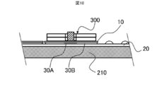
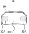
- the adhesive 30 has a partially cured cured portion 30A and an uncured portion 30B.
- the adhesive 30 in which only the cured portion 30A is cured has the strength to hold the position of the solar cell 10 with respect to the substrate 20 even when the substrate 20 is conveyed.
- the CPU 401 controls the suction drive unit 313 to release the suction of the head 300. Then, the CPU 401 controls the transport mechanism 220 to retract the head 300 from the stage 210 (fifth step: step S5). Even after the head 300 is retracted, the position of the solar cell 10 with respect to the substrate 20 and the distance between the solar cell 10 and the substrate 20 are maintained by the cured portion 30A of the adhesive 30.
- the CPU 401 determines whether or not the arrangement of the specified number of solar cells 10 on the substrate 20 is completed (step S6). If the arrangement of the designated number of solar cells 10 is not completed (step S6: No), the process returns to the second step of transporting the next solar cells 10.
- the designated number of sheets is a value determined in advance by the number of solar cells 10 arranged on one substrate 20.
- step S6 When it is determined that the arrangement of the specified number of solar cells 10 has been completed (step S6: Yes), an overall curing step of curing the uncured portion 30B of the adhesive 30 (sixth step: a step of curing the rest of the adhesive 30). : Step S7) is performed.
- the uncured portion 30B on the substrate 20 on which the specified number of solar cells 10 are arranged is cured at room temperature. Further, as shown in FIG. 12, the uncured portion 30B may be cured by heating the entire substrate 20 using a heating device such as an infrared heater 250 or a constant temperature bath for circulating warm air.
- the solar cell panel 100 shown in FIG. 1 is completed by wiring adjacent solar cell 10s with a conducting wire or a bus bar.
- the solar cell 10 can be pressed with an appropriate pressure to spread the adhesive 30. Further, since the substrate 20 coated with the adhesive 30 is not turned upside down, it is possible to suppress the collapse of the coating pattern of the adhesive 30 and prevent bubbles from being generated in the adhesive 30.
- the heating unit 350 is a part of the adhesive 30 in a state where the adhesive 30 is pressurized by the pressure plate 320 and the solar cell 10 is held in position with respect to the substrate 20 by the pressure plate 320. Therefore, a plurality of solar cell 10s can be efficiently positioned on the substrate 20 in a short time. Further, since the heating unit 350 is smaller than the pressure plate 320, the heat capacity of the heating unit 350 can be reduced, and the temperature raising time and the temperature lowering time of the heating unit 350 can be shortened.
- the heat transfer unit 351 of the heating unit 350 is movable by the support unit 354 along the Z direction and is supported so as to be inclined according to the inclination of the surface of the solar cell 10, the heat transfer unit 351 is supported by the sun.
- the thermal resistance between the heat transfer portion 351 and the solar cell 10 can be reduced, and a part of the adhesive 30 can be cured in a short time. Therefore, the solar cell panel manufacturing apparatus 200 can efficiently bond the plurality of solar cell cells 10 to the substrate 20 in a short time.
- a plurality of solar cell cells 10 can be efficiently bonded to the substrate 20 in a short time.
- the solar cell 10 since the solar cell 10 is arranged by the head 300, the solar cell 10 can be positioned without using a member that contacts and positions the solar cell 10. Therefore, damage to the solar cell 10 can be suppressed.
- the thickness of the layered adhesive 30 can be controlled by adjusting the period from when the adhesive 30 is spread until the temperature of the heating unit 350 is raised. Further, the thickness of the layered adhesive 30 can be controlled by adjusting the force with which the pressure plate 320 pressurizes the adhesive 30 and the force with which the heating unit 350 abuts on the solar cell 10.
- the lower surface of the heat transfer portion 351 and the lower surface of the pressure plate 320 are in a flush relationship.
- the heating unit 350 heats the adhesive 30 to heat the adhesive 30. Increases the viscosity of.
- the viscosity of the adhesive 30 increases after the adhesive 30 has spread.
- the solar cell panel manufacturing apparatus 200 may further include an actuator 361 that drives the heat transfer unit 351 up and down with respect to the pressure plate 320.
- the actuator 361 is, for example, an air cylinder, a solenoid, or the like.
- the solar cell panel manufacturing apparatus 200 raises the heat transfer unit 351 by the actuator 361 as shown in FIG. Further, as shown in FIG. 14, the solar cell panel manufacturing apparatus 200 lowers the heat transfer unit 351.
- the solar cell panel manufacturing apparatus 200 can bring the heat transfer unit 351 into contact with the solar cell 10 while maintaining the state in which the solar cell 10 is attracted or pressurized. Further, the solar cell panel manufacturing apparatus 200 can separate the heat transfer unit 351 from the solar cell 10 while maintaining the state in which the solar cell 10 is attracted or pressurized.
- the CPU 401 raises the heat transfer unit 351 by controlling the operation of the actuator 361 while pressurizing the solar cell 10 to spread the adhesive 30, and separates the heat transfer unit 351 from the solar cell 10. Let me. As a result, the CPU 401 blocks the heat conduction from the heat transfer unit 351 to the adhesive 30. On the other hand, when the adhesive 30 is partially cured, the heat transfer portion 351 is lowered by controlling the operation of the actuator 361, and the heat transfer portion 351 is brought into contact with the solar cell 10. As a result, the CPU 401 transfers heat from the heat transfer unit 351 to the adhesive 30.
- the heat transfer unit 351 When the heat transfer unit 351 is lowered, the heat transfer unit 351 is separated from the actuator 361, so that the heat transfer unit 350 abuts heat after the heat transfer unit 351 comes into contact with the solar cell 10 due to its own weight.
- the structure is such that the portion 351 passively follows the surface of the solar cell 10 and escapes.
- the solar cell panel manufacturing apparatus 200 conveys the solar cell 10 in a state of being separated from the solar cell 10 while maintaining the heat transfer unit 351 in a high temperature state, and applies the adhesive 30. Can be pressurized. As a result, the solar cell panel manufacturing apparatus 200 can convey the solar cell 10 and spread the adhesive 30 without transferring the heat of the heat transfer unit 351 to the solar cell 10. Further, the solar cell panel manufacturing apparatus 200 can partially heat the adhesive 30 via the solar cell 10 by lowering the heat transfer unit 351 after spreading the adhesive 30.
- the temperature of the heat transfer portion 351 is about 80 ° C., which is the temperature at which the viscosity of the adhesive 30 does not increase, to about 120, which is the temperature at which the adhesive 30 cures. It takes several tens of seconds to change to ° C. Further, when the temperature of the heat transfer portion 351 is lowered from the temperature at which the adhesive 30 is cured to the temperature at which the viscosity of the adhesive 30 does not increase, it takes about 1 to 2 minutes.
- the solar cell panel manufacturing apparatus 200 of the first embodiment may not be able to carry the solar cell 10 during these periods.
- the solar cell panel manufacturing apparatus 200 of the present embodiment can change the amount of heat given to the adhesive 30 without waiting for the completion of the temperature change of the heat transfer unit 351. Therefore, the solar cell panel manufacturing apparatus 200 of the present embodiment can further increase the number of manufactured sheets per unit time.
- one heat transfer unit 351 is arranged in the head 300, but a plurality of heat transfer units 351 may be arranged in the head 300.
- the head 300A shown on the side surface in FIG. 15 includes two heat transfer portions 351.
- two cured portions 30A are formed in the layer of the adhesive 30.
- three or more heat transfer portions 351 may be arranged on the head 300, and as shown in FIG. 17, three or more cured portions 30A may be formed in the layer of the adhesive 30.
- the heat transfer unit 351 may be provided near the long side of the solar cell 10 in order to prevent the position of the solar cell 10 from being displaced due to the transportation of the solar cell panel 100.
- the solar cell row 12 to which the electrodes of the plurality of solar cells 10 are connected in advance may be arranged on the substrate 20.
- four heads 300B of the present embodiment are connected to the heads 300, which is the same number as the number of solar cells 10 forming the solar cell row 12.
- the position of the solar cell 10 with respect to the substrate 20 may be determined by controlling the position of the head 300B with respect to the stage 210 by the pattern recognition technique.
- the pressure plate 320 is formed of one plate, but the pressure plate 320 may be formed of a plurality of plates.
- the head 300C of the present embodiment includes a pressure plate 320A having a first plate 321 and a second plate 322 instead of the pressure plate 320 of the first embodiment.
- the pressure plate 320A presses the solar cell 10 from the upper surface of the solar cell 10 in the same manner as the pressure plate 320 of the first embodiment. Further, the pressure plate 320A holds the position of the solar cell 10 with respect to the substrate 20. It is desirable that the pressure plate 320A is formed smaller than the outer shape of the solar cell 10.
- the first plate 321 is located on the solar cell 10 side and is in contact with the solar cell 10.
- the first plate 321 is provided with an intake passage opened on the lower surface and an opening on which the heating portion 350 is located. It is desirable that the rigidity of the first plate 321 is higher than the rigidity of the second plate 322.
- the Young's modulus of the first plate 321 is preferably 100 times or more the Young's modulus of the second plate 322.
- the first plate 321 is formed of metal, monomer cast nylon, or the like.
- the second plate 322 is located on the opposite side of the solar cell 10 and is arranged between the suction plate 311 and the first plate 321.
- the second plate 322 is provided with an intake passage communicating with the intake passage of the suction plate 311 and the intake passage of the first plate 321 and an opening in which the heating portion 350 is located.
- the second plate 322 is formed of, for example, ethylene propylene diene rubber.
- the solar cell 10 may be deformed in the out-of-plane direction due to pressurization, and the thickness of the layered adhesive 30 may become non-uniform.
- the rigidity of the first plate 321 located on the solar cell 10 side is high, the solar cell 10 is suppressed from being deformed in the out-of-plane direction, and the thickness of the layered adhesive 30 is made uniform. it can.
- the rigidity of the second plate 322 located on the opposite side of the solar cell 10 is small, the second plate 322 deforms the waviness, unevenness, etc. of the surface 210a of the stage 210 and the substrate 20 as shown in FIG. And absorb. Therefore, the thickness of the layered adhesive 30 can be made more uniform.
- the heating unit 350 is arranged on the head 300, but the heating unit 350 may be provided on the stage 210. As shown in FIG. 21, the head 300D does not include a heating unit 350.
- a recessed portion 216 is formed at a position where the solar cell 10 of the stage 210 is to be arranged.
- the heating portion 211 is arranged in the recess portion 216.
- the heat transfer portion 213 is arranged in the recess portion 216 via the heat insulating material 212.
- a heater 214 and a temperature sensor 215 are arranged in the heat transfer unit 213.
- the heat transfer unit 213 is independent for each solar cell 10 or solar cell row 12 via the heat insulating material 212. As a result, when the adjacent solar cell 10 or the solar cell row 12 is attached, it is possible to suppress an increase in the temperature of the adhesive 30 before the attachment.
- the heat transfer unit 213 is not equipped with a mechanism for passively following the surface shape of the solar cell 10 and a mechanism for escaping.
- the heat transfer unit 213 is fixed to the stage 210.
- the surface 210a of the stage 210 and the upper surface of the heat transfer portion 213 are formed as smooth surfaces with few irregularities.
- the heat transfer unit 213 faces the central portion of the solar cell 10 in order to reduce the heat capacity of the temperature rising portion and increase the temperature rise rate of the heat transfer unit 213, instead of curing the entire layer of the adhesive 30. It is placed only in position.
- This embodiment is particularly excellent when the substrate 20 is in the form of a sheet. By fixing the outer circumference of the sheet-shaped substrate 20 with a frame, the sheet-shaped substrate 20 is moved together with the frame to the next entire adhesive curing step in a state where wrinkles, sagging, etc. are suppressed.
- the structure of the head 300D is simple and the wiring to the heater 214 and the temperature sensor 215 is arranged in the stage 210 where there is little movement, maintenance of the solar cell panel manufacturing apparatus 200 and maintenance and Adjustment work becomes easy.
- the adhesive 30 can be efficiently heated by heating the adhesive 30 from the substrate 20 side. Therefore, the temperature at which the adhesive 30 is heated can be lowered.
- the pressure plate 320 of the head 300 from an elastic body, it is possible to prevent a local load from being applied to the solar cell 10. In addition, damage to the solar cell 10 due to pinching can be suppressed.
- the adhesive 30 of the solar cell panel 100 will be described in detail.
- the adhesive 30 adheres the solar cell 10 to the substrate 20.
- the adhesive 30 of the solar cell panel 100 is a layered cured adhesive.
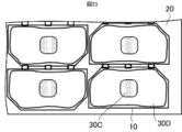
- the adhesive 30 of the solar cell panel 100 has a first region 30C cured first and a second region 30D cured in a state where the first region 30C is cured. ..
- the first region 30C corresponds to the cured portion 30A partially cured by the curing step of the method for manufacturing the solar cell panel 100 in the first embodiment.
- the second region 30D corresponds to a portion obtained by curing the uncured portion 30B by the step of curing the rest of the adhesive 30 in the method for manufacturing the solar cell panel 100 in the first embodiment.
- the first region 30C is preferably located at one to three locations with respect to one solar cell 10.
- the area of the first region 30C is preferably 20% or less of the area of the region 30E to which the solar cell 10 is adhered by the adhesive 30.
- the time for the temperature of the adhesive 30 to reach the curing temperature can be shortened, and the solar cell panel 100 can be efficiently manufactured.
- the size of the first region 30C, that is, the cured portion 30A the dimensional change of the substrate 20 due to thermal expansion can be minimized, and the solar cell 10 can be arranged at a more accurate position.
- the entire process shown in FIG. 6 may be carried out using the solar cell panel manufacturing apparatus 200. ..
- the transport mechanism 220 has been illustrated to transport the head 300 and the solar cell 10, but the transport mechanism 220 is an example.
- the solar cell panel manufacturing apparatus 200 may include, for example, a multi-axis robot arm capable of transporting the heads 300, 300A to 300D in the X, Y, and Z directions.
- thermosetting adhesive is used as the adhesive 30.
- the solar cell panel manufacturing apparatus 200 includes heating units 211 and 350 for curing the adhesive 30.
- an adhesive other than the thermosetting type may be used.
- a photocurable adhesive may be used as the adhesive 30.
- the solar cell panel manufacturing apparatus 200 includes, instead of the heating portions 211 and 350, a cured portion that cures a part of the layer of the adhesive 30 according to the characteristics of the adhesive.
- the heating portions 211 and 350 are examples of cured portions.
- the heads 300, 300A to 300D may hold the solar cell 10 by any holding means.
- the heads 300, 300A to 300D may grip the solar cell 10.
- the pressure plates 320 and 320A have a shape corresponding to the shape of the solar cell 10. Further, it is preferable that the pressure plates 320 and 320A can be replaced according to the shape of the solar cell 10.
- control unit 400 shown in FIG. 5 and the solar cell panel manufacturing method shown in FIG. 6 are also examples, and the control unit 400, the solar cell panel manufacturing method, and the like are not limited thereto.
- the substrate 20 of the solar cell panel 100 may have translucency.
- the substrate 20 may be, for example, a translucent or transparent sheet made of resin. Since the substrate 20 has translucency, as shown in FIG. 23, the cured state of the adhesive 30, the spread of the first region 30C of the adhesive 30, and the like can be visually inspected from the substrate 20 side, and the solar cell panel. The quality in each of the 100 manufacturing processes can be easily inspected. Inspections such as the cured state of the adhesive 30 and the spread of the first region 30C of the adhesive 30 may be performed using a camera, an optical sensor, or the like.
Landscapes
- Photovoltaic Devices (AREA)
- Life Sciences & Earth Sciences (AREA)
- Engineering & Computer Science (AREA)
- Sustainable Development (AREA)
- Sustainable Energy (AREA)
Priority Applications (3)
| Application Number | Priority Date | Filing Date | Title |
|---|---|---|---|
| US17/771,840 US12132139B2 (en) | 2019-12-27 | 2020-10-05 | Solar cell panel manufacturing apparatus, solar cell panel manufacturing method, and solar cell panel |
| JP2021566831A JP7337194B2 (ja) | 2019-12-27 | 2020-10-05 | 太陽電池パネル製造装置及び太陽電池パネル製造方法 |
| EP20905660.5A EP4084092A4 (en) | 2019-12-27 | 2020-10-05 | SOLAR CELL PANEL MANUFACTURING DEVICE, SOLAR CELL PANEL MANUFACTURING METHOD AND SOLAR CELL PANEL MANUFACTURING |
Applications Claiming Priority (2)
| Application Number | Priority Date | Filing Date | Title |
|---|---|---|---|
| JP2019237775 | 2019-12-27 | ||
| JP2019-237775 | 2019-12-27 |
Publications (1)
| Publication Number | Publication Date |
|---|---|
| WO2021131219A1 true WO2021131219A1 (ja) | 2021-07-01 |
Family
ID=76575877
Family Applications (1)
| Application Number | Title | Priority Date | Filing Date |
|---|---|---|---|
| PCT/JP2020/037685 Ceased WO2021131219A1 (ja) | 2019-12-27 | 2020-10-05 | 太陽電池パネル製造装置、太陽電池パネル製造方法及び太陽電池パネル |
Country Status (4)
| Country | Link |
|---|---|
| US (1) | US12132139B2 (https=) |
| EP (1) | EP4084092A4 (https=) |
| JP (1) | JP7337194B2 (https=) |
| WO (1) | WO2021131219A1 (https=) |
Citations (6)
| Publication number | Priority date | Publication date | Assignee | Title |
|---|---|---|---|---|
| US4267003A (en) * | 1979-08-14 | 1981-05-12 | Trw Inc. | Automatic solar cell glassing machine and method |
| JPH09181342A (ja) | 1995-12-26 | 1997-07-11 | Sharp Corp | 太陽電池セルとカバーガラスの接着方法および接着装置 |
| JP2001177138A (ja) * | 1999-12-14 | 2001-06-29 | Toshiba Corp | 太陽電池パネルの製造装置及び製造方法 |
| JP2002211498A (ja) | 2001-01-15 | 2002-07-31 | Mitsubishi Electric Corp | 太陽電池パネルの接着方法および太陽電池パネル |
| JP2003037279A (ja) * | 2001-07-24 | 2003-02-07 | Fuji Electric Co Ltd | 太陽電池モジュールとその製造方法 |
| WO2013179564A1 (ja) * | 2012-05-28 | 2013-12-05 | パナソニック株式会社 | 太陽電池及びその製造方法 |
Family Cites Families (5)
| Publication number | Priority date | Publication date | Assignee | Title |
|---|---|---|---|---|
| JPH02255460A (ja) | 1989-03-29 | 1990-10-16 | Toshiba Corp | 板材の自動貼付け装置 |
| JP4248389B2 (ja) * | 2003-12-25 | 2009-04-02 | シャープ株式会社 | 太陽電池モジュールの製造方法と太陽電池モジュールの製造装置 |
| JP2011114205A (ja) | 2009-11-27 | 2011-06-09 | Sharp Corp | 太陽電池モジュールの製造方法および太陽電池モジュール |
| EP2546889B1 (en) | 2011-07-12 | 2020-06-17 | Airbus Defence and Space GmbH | Solar cell assembly and method of fabrication of solar cell assembly |
| US9608156B2 (en) * | 2015-07-09 | 2017-03-28 | SolAcro Technologies Corp. | Assembly and mounting of solar cells on space panels |
-
2020
- 2020-10-05 WO PCT/JP2020/037685 patent/WO2021131219A1/ja not_active Ceased
- 2020-10-05 EP EP20905660.5A patent/EP4084092A4/en active Pending
- 2020-10-05 US US17/771,840 patent/US12132139B2/en active Active
- 2020-10-05 JP JP2021566831A patent/JP7337194B2/ja active Active
Patent Citations (6)
| Publication number | Priority date | Publication date | Assignee | Title |
|---|---|---|---|---|
| US4267003A (en) * | 1979-08-14 | 1981-05-12 | Trw Inc. | Automatic solar cell glassing machine and method |
| JPH09181342A (ja) | 1995-12-26 | 1997-07-11 | Sharp Corp | 太陽電池セルとカバーガラスの接着方法および接着装置 |
| JP2001177138A (ja) * | 1999-12-14 | 2001-06-29 | Toshiba Corp | 太陽電池パネルの製造装置及び製造方法 |
| JP2002211498A (ja) | 2001-01-15 | 2002-07-31 | Mitsubishi Electric Corp | 太陽電池パネルの接着方法および太陽電池パネル |
| JP2003037279A (ja) * | 2001-07-24 | 2003-02-07 | Fuji Electric Co Ltd | 太陽電池モジュールとその製造方法 |
| WO2013179564A1 (ja) * | 2012-05-28 | 2013-12-05 | パナソニック株式会社 | 太陽電池及びその製造方法 |
Also Published As
| Publication number | Publication date |
|---|---|
| EP4084092A1 (en) | 2022-11-02 |
| EP4084092A4 (en) | 2023-06-14 |
| JP7337194B2 (ja) | 2023-09-01 |
| US20220376129A1 (en) | 2022-11-24 |
| JPWO2021131219A1 (https=) | 2021-07-01 |
| US12132139B2 (en) | 2024-10-29 |
Similar Documents
| Publication | Publication Date | Title |
|---|---|---|
| KR100730562B1 (ko) | 액정패널 제조장치 | |
| JP6518461B2 (ja) | 実装装置および実装方法 | |
| KR101380978B1 (ko) | 합착장치 | |
| TWI494220B (zh) | A bonding apparatus and method of a substrate, and a substrate bonded head | |
| WO2017187721A1 (ja) | 加圧装置および加圧方法 | |
| CN112060741A (zh) | 曲面贴合装置 | |
| CN115534381A (zh) | 一种基于基板保压的液压式保压工装及保压系统 | |
| JP4666546B2 (ja) | 加圧装置とこれを用いたバンプボンディング装置、貼り付け装置、及び圧着装置 | |
| JP7337194B2 (ja) | 太陽電池パネル製造装置及び太陽電池パネル製造方法 | |
| CN111421834B (zh) | 热压装置 | |
| KR101366519B1 (ko) | 기판 조립 장치 | |
| CN115990554A (zh) | 薄型显示面板移送及涂层装置 | |
| KR102807406B1 (ko) | 본딩 장치 및 본딩 헤드 조정 방법 | |
| JP5961366B2 (ja) | ワーク設置装置およびワーク設置方法 | |
| JP6336510B2 (ja) | 加圧方法および加圧装置 | |
| CN118658797B (zh) | 一种激光键合装置 | |
| TW202236451A (zh) | 基板黏貼裝置及基板黏貼方法 | |
| JP4371939B2 (ja) | 基板搬入装置、部品実装装置、及び基板搬入方法 | |
| CN218144415U (zh) | 一种自动贴片系统 | |
| JP6442363B2 (ja) | 搬送装置 | |
| JP7487038B2 (ja) | 治具の製造方法、治具、3次元造形物製造装置、及び3次元造形物の製造方法 | |
| JP2022125261A (ja) | 複合材料構造物の製造方法 | |
| JP7152881B2 (ja) | 複合材料構造物の製造用治具 | |
| KR20210136442A (ko) | 유연디스플레이 소자 본딩 테이블 구조 | |
| CN219379269U (zh) | 一种焊带压持治具及焊接装置 |
Legal Events
| Date | Code | Title | Description |
|---|---|---|---|
| 121 | Ep: the epo has been informed by wipo that ep was designated in this application |
Ref document number: 20905660 Country of ref document: EP Kind code of ref document: A1 |
|
| ENP | Entry into the national phase |
Ref document number: 2021566831 Country of ref document: JP Kind code of ref document: A |
|
| NENP | Non-entry into the national phase |
Ref country code: DE |
|
| ENP | Entry into the national phase |
Ref document number: 2020905660 Country of ref document: EP Effective date: 20220727 |