WO2017187721A1 - 加圧装置および加圧方法 - Google Patents
加圧装置および加圧方法 Download PDFInfo
- Publication number
- WO2017187721A1 WO2017187721A1 PCT/JP2017/005359 JP2017005359W WO2017187721A1 WO 2017187721 A1 WO2017187721 A1 WO 2017187721A1 JP 2017005359 W JP2017005359 W JP 2017005359W WO 2017187721 A1 WO2017187721 A1 WO 2017187721A1
- Authority
- WO
- WIPO (PCT)
- Prior art keywords
- workpiece
- mold
- heating
- mounting table
- lower mold
- Prior art date
Links
Images


Classifications
-
- H—ELECTRICITY
- H01—ELECTRIC ELEMENTS
- H01L—SEMICONDUCTOR DEVICES NOT COVERED BY CLASS H10
- H01L21/00—Processes or apparatus adapted for the manufacture or treatment of semiconductor or solid state devices or of parts thereof
- H01L21/67—Apparatus specially adapted for handling semiconductor or electric solid state devices during manufacture or treatment thereof; Apparatus specially adapted for handling wafers during manufacture or treatment of semiconductor or electric solid state devices or components ; Apparatus not specifically provided for elsewhere
- H01L21/67005—Apparatus not specifically provided for elsewhere
- H01L21/67011—Apparatus for manufacture or treatment
- H01L21/67092—Apparatus for mechanical treatment
-
- B—PERFORMING OPERATIONS; TRANSPORTING
- B29—WORKING OF PLASTICS; WORKING OF SUBSTANCES IN A PLASTIC STATE IN GENERAL
- B29C—SHAPING OR JOINING OF PLASTICS; SHAPING OF MATERIAL IN A PLASTIC STATE, NOT OTHERWISE PROVIDED FOR; AFTER-TREATMENT OF THE SHAPED PRODUCTS, e.g. REPAIRING
- B29C65/00—Joining or sealing of preformed parts, e.g. welding of plastics materials; Apparatus therefor
- B29C65/48—Joining or sealing of preformed parts, e.g. welding of plastics materials; Apparatus therefor using adhesives, i.e. using supplementary joining material; solvent bonding
-
- B—PERFORMING OPERATIONS; TRANSPORTING
- B29—WORKING OF PLASTICS; WORKING OF SUBSTANCES IN A PLASTIC STATE IN GENERAL
- B29C—SHAPING OR JOINING OF PLASTICS; SHAPING OF MATERIAL IN A PLASTIC STATE, NOT OTHERWISE PROVIDED FOR; AFTER-TREATMENT OF THE SHAPED PRODUCTS, e.g. REPAIRING
- B29C33/00—Moulds or cores; Details thereof or accessories therefor
- B29C33/02—Moulds or cores; Details thereof or accessories therefor with incorporated heating or cooling means
-
- B—PERFORMING OPERATIONS; TRANSPORTING
- B29—WORKING OF PLASTICS; WORKING OF SUBSTANCES IN A PLASTIC STATE IN GENERAL
- B29C—SHAPING OR JOINING OF PLASTICS; SHAPING OF MATERIAL IN A PLASTIC STATE, NOT OTHERWISE PROVIDED FOR; AFTER-TREATMENT OF THE SHAPED PRODUCTS, e.g. REPAIRING
- B29C43/00—Compression moulding, i.e. applying external pressure to flow the moulding material; Apparatus therefor
- B29C43/02—Compression moulding, i.e. applying external pressure to flow the moulding material; Apparatus therefor of articles of definite length, i.e. discrete articles
- B29C43/18—Compression moulding, i.e. applying external pressure to flow the moulding material; Apparatus therefor of articles of definite length, i.e. discrete articles incorporating preformed parts or layers, e.g. compression moulding around inserts or for coating articles
-
- B—PERFORMING OPERATIONS; TRANSPORTING
- B29—WORKING OF PLASTICS; WORKING OF SUBSTANCES IN A PLASTIC STATE IN GENERAL
- B29C—SHAPING OR JOINING OF PLASTICS; SHAPING OF MATERIAL IN A PLASTIC STATE, NOT OTHERWISE PROVIDED FOR; AFTER-TREATMENT OF THE SHAPED PRODUCTS, e.g. REPAIRING
- B29C66/00—General aspects of processes or apparatus for joining preformed parts
- B29C66/01—General aspects dealing with the joint area or with the area to be joined
- B29C66/03—After-treatments in the joint area
- B29C66/032—Mechanical after-treatments
- B29C66/0322—Post-pressing without reshaping, i.e. keeping the joint under pressure after joining
-
- B—PERFORMING OPERATIONS; TRANSPORTING
- B29—WORKING OF PLASTICS; WORKING OF SUBSTANCES IN A PLASTIC STATE IN GENERAL
- B29C—SHAPING OR JOINING OF PLASTICS; SHAPING OF MATERIAL IN A PLASTIC STATE, NOT OTHERWISE PROVIDED FOR; AFTER-TREATMENT OF THE SHAPED PRODUCTS, e.g. REPAIRING
- B29C66/00—General aspects of processes or apparatus for joining preformed parts
- B29C66/01—General aspects dealing with the joint area or with the area to be joined
- B29C66/03—After-treatments in the joint area
- B29C66/034—Thermal after-treatments
-
- B—PERFORMING OPERATIONS; TRANSPORTING
- B29—WORKING OF PLASTICS; WORKING OF SUBSTANCES IN A PLASTIC STATE IN GENERAL
- B29C—SHAPING OR JOINING OF PLASTICS; SHAPING OF MATERIAL IN A PLASTIC STATE, NOT OTHERWISE PROVIDED FOR; AFTER-TREATMENT OF THE SHAPED PRODUCTS, e.g. REPAIRING
- B29C66/00—General aspects of processes or apparatus for joining preformed parts
- B29C66/70—General aspects of processes or apparatus for joining preformed parts characterised by the composition, physical properties or the structure of the material of the parts to be joined; Joining with non-plastics material
- B29C66/71—General aspects of processes or apparatus for joining preformed parts characterised by the composition, physical properties or the structure of the material of the parts to be joined; Joining with non-plastics material characterised by the composition of the plastics material of the parts to be joined
-
- H—ELECTRICITY
- H01—ELECTRIC ELEMENTS
- H01L—SEMICONDUCTOR DEVICES NOT COVERED BY CLASS H10
- H01L21/00—Processes or apparatus adapted for the manufacture or treatment of semiconductor or solid state devices or of parts thereof
- H01L21/67—Apparatus specially adapted for handling semiconductor or electric solid state devices during manufacture or treatment thereof; Apparatus specially adapted for handling wafers during manufacture or treatment of semiconductor or electric solid state devices or components ; Apparatus not specifically provided for elsewhere
- H01L21/67005—Apparatus not specifically provided for elsewhere
- H01L21/67011—Apparatus for manufacture or treatment
- H01L21/67098—Apparatus for thermal treatment
- H01L21/67109—Apparatus for thermal treatment mainly by convection
-
- H—ELECTRICITY
- H01—ELECTRIC ELEMENTS
- H01L—SEMICONDUCTOR DEVICES NOT COVERED BY CLASS H10
- H01L21/00—Processes or apparatus adapted for the manufacture or treatment of semiconductor or solid state devices or of parts thereof
- H01L21/67—Apparatus specially adapted for handling semiconductor or electric solid state devices during manufacture or treatment thereof; Apparatus specially adapted for handling wafers during manufacture or treatment of semiconductor or electric solid state devices or components ; Apparatus not specifically provided for elsewhere
- H01L21/67005—Apparatus not specifically provided for elsewhere
- H01L21/67011—Apparatus for manufacture or treatment
- H01L21/67126—Apparatus for sealing, encapsulating, glassing, decapsulating or the like
-
- B—PERFORMING OPERATIONS; TRANSPORTING
- B29—WORKING OF PLASTICS; WORKING OF SUBSTANCES IN A PLASTIC STATE IN GENERAL
- B29C—SHAPING OR JOINING OF PLASTICS; SHAPING OF MATERIAL IN A PLASTIC STATE, NOT OTHERWISE PROVIDED FOR; AFTER-TREATMENT OF THE SHAPED PRODUCTS, e.g. REPAIRING
- B29C33/00—Moulds or cores; Details thereof or accessories therefor
- B29C33/02—Moulds or cores; Details thereof or accessories therefor with incorporated heating or cooling means
- B29C2033/023—Thermal insulation of moulds or mould parts
-
- H—ELECTRICITY
- H01—ELECTRIC ELEMENTS
- H01L—SEMICONDUCTOR DEVICES NOT COVERED BY CLASS H10
- H01L2224/00—Indexing scheme for arrangements for connecting or disconnecting semiconductor or solid-state bodies and methods related thereto as covered by H01L24/00
- H01L2224/73—Means for bonding being of different types provided for in two or more of groups H01L2224/10, H01L2224/18, H01L2224/26, H01L2224/34, H01L2224/42, H01L2224/50, H01L2224/63, H01L2224/71
- H01L2224/732—Location after the connecting process
- H01L2224/73201—Location after the connecting process on the same surface
- H01L2224/73203—Bump and layer connectors
- H01L2224/73204—Bump and layer connectors the bump connector being embedded into the layer connector
-
- H—ELECTRICITY
- H01—ELECTRIC ELEMENTS
- H01L—SEMICONDUCTOR DEVICES NOT COVERED BY CLASS H10
- H01L2224/00—Indexing scheme for arrangements for connecting or disconnecting semiconductor or solid-state bodies and methods related thereto as covered by H01L24/00
- H01L2224/74—Apparatus for manufacturing arrangements for connecting or disconnecting semiconductor or solid-state bodies and for methods related thereto
- H01L2224/75—Apparatus for connecting with bump connectors or layer connectors
-
- H—ELECTRICITY
- H01—ELECTRIC ELEMENTS
- H01L—SEMICONDUCTOR DEVICES NOT COVERED BY CLASS H10
- H01L2224/00—Indexing scheme for arrangements for connecting or disconnecting semiconductor or solid-state bodies and methods related thereto as covered by H01L24/00
- H01L2224/80—Methods for connecting semiconductor or other solid state bodies using means for bonding being attached to, or being formed on, the surface to be connected
- H01L2224/83—Methods for connecting semiconductor or other solid state bodies using means for bonding being attached to, or being formed on, the surface to be connected using a layer connector
- H01L2224/831—Methods for connecting semiconductor or other solid state bodies using means for bonding being attached to, or being formed on, the surface to be connected using a layer connector the layer connector being supplied to the parts to be connected in the bonding apparatus
- H01L2224/83101—Methods for connecting semiconductor or other solid state bodies using means for bonding being attached to, or being formed on, the surface to be connected using a layer connector the layer connector being supplied to the parts to be connected in the bonding apparatus as prepeg comprising a layer connector, e.g. provided in an insulating plate member
Definitions
- the present invention relates to a pressurizing apparatus and a pressurizing method for pressurizing and heating a workpiece with a plurality of pressurizing dies.
- Patent Documents 1 and 2 disclose an apparatus that sandwiches and pressurizes a workpiece between a lower mold and an upper mold and heats the workpiece with a heater built in the mold.
- a pressure device After pressurization and heating of the workpiece are completed, the workpiece is cooled while maintaining the pressurized state.
- the mold is separated from the workpiece and the workpiece is taken out.
- JP 2004-296746 A Japanese Patent Laid-Open No. 2007-896
- a heater and a refrigerant flow path are provided inside the mold, and the mold is heated or cooled according to the progress of processing. It was. However, in such a configuration, it takes time to raise the mold once cooled to a predetermined temperature, or to lower the mold once heated to a predetermined temperature, leading to an increase in the processing time of the workpiece. It was. In addition, when trying to quickly heat the mold using a heater, the mold temperature is likely to overshoot that temporarily exceeds the set temperature, and there is a risk that unexpected high heat will be added to the workpiece. .
- an object of the present invention is to provide a pressurizing apparatus and a pressurizing method that can more appropriately control the temperature of the workpiece in a shorter time.
- the pressurizing apparatus of the present invention includes a mounting table on which a workpiece is mounted, an upper mold that pressurizes the workpiece mounted on the mounting table from above, and a lower mold that is heated in advance by a heating unit. And a lower mold for heating that pressurizes the workpiece while sandwiching the mounting table together with the upper mold, and a lower mold that is cooled in advance by a cooling means, the upper mold And a cooling lower mold that cools the work piece while pressurizing it by sandwiching the mounting table, and a control device that controls the driving of the mold, and the progress of the pressure treatment of the work piece And a control device that switches a lower mold that contributes to pressurization of the workpiece to a lower mold for heating or a lower mold for cooling.
- the intermediate pad further includes an interposition pad interposed between the upper mold and the workpiece, and the interposition pad is flexibly deformed according to the shape of the workpiece, and the flexible A heat insulating layer interposed between the layer and the workpiece to insulate between the workpiece and the flexible layer.
- the lower mold for heating heats the workpiece to a temperature higher than the heat resistant temperature of the flexible layer.
- control device causes the intermediate pad to contact the workpiece, holds the workpiece with the intermediate pad, and then heats and pressurizes the workpiece with the lower heating mold. It is desirable to let
- the side mold is further disposed around the upper mold and is in close contact with the mounting table, thereby forming a sealed space around the workpiece together with the upper mold and the mounting table, A suction device that sucks air in a sealed space and places a vacuum around the workpiece, and the control device sets the side mold to the mounting table prior to pressurization of the workpiece. It is preferable that the sealed space is formed by contacting the closed space and the suction device is driven to bring the sealed space into a vacuum state.
- a pressurizing method for pressurizing and heating a workpiece mounted on a mounting table wherein an upper mold and a heating lower mold heated in advance by a heating means are provided.
- the present invention in order to switch the lower mold that contributes to pressurization of the workpiece to the pre-heated lower mold or the pre-cooled cooling lower mold according to the progress of the pressurizing process, the time required for heating and cooling can be greatly reduced, and the temperature of the workpiece can be controlled appropriately.
- the workpiece 100 in this embodiment includes a plurality of electronic components 112 that are bonded using a thermosetting adhesive.
- the workpiece 100 includes a substrate 110, an electronic component 112 such as a circuit element disposed on the substrate 110, and a sheet-like sheet interposed between the substrate 110 and the electronic component 112.
- Wiring 111 is formed in a predetermined pattern on the surface of the substrate 110.
- the adhesive 114 is made of a thermosetting adhesive and is disposed between the electronic component 112 and the substrate 110.
- the adhesive 114 is in the form of a sheet having a predetermined shape in the initial stage before the start of pressing and heating.
- the adhesive 114 softens and has fluidity when it exceeds a predetermined glass transition temperature Tg, and then irreversibly cures when the temperature further rises and exceeds a predetermined curing temperature Tc.
- the workpiece 100 When joining the electronic component 112 to the substrate 110, the workpiece 100 is sandwiched between the upper mold and the lower mold and pressurized and heated. By heating, the adhesive 114 exceeds the glass transition temperature Tg and softens. Further, when the heating is continued, the adhesive 114 reaches the curing temperature Tc and is cured. By continuing to pressurize the workpiece 100 during the period from when the adhesive 114 is softened until it hardens, the portion of the adhesive 114 sandwiched between the wiring 111 and the bump 113 is compressed, and the bump 113 and the wiring 111 are compressed. Is in a conductive state.
- the interposer pad 24 is provided in the upper mold 20 in this embodiment.
- the intervening pad 24 has the flexibility to be deformed according to the shape of the workpiece 100.
- the intervening pad 24 wraps around the electronic component 112 and the adhesive 114 as shown in FIG. Then, the pressing force from the upper mold 20 is transmitted not only above the electronic component 112 and the adhesive 114 but also to the side via the interposing pad 24.
- the workpiece 100 is cooled while maintaining the pressurized state of the workpiece 100 in order to prevent the workpiece 100 from warping due to the difference in thermal expansion between the front and back surfaces. And if the temperature of the to-be-processed object 100 falls to the temperature which can be taken out, pressurization will be cancelled
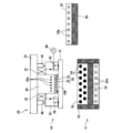
- FIG. 2 is a diagram illustrating a configuration of the pressurizing apparatus 10 according to the present embodiment.
- the pressurizing device 10 includes a mounting table 12 on which the workpiece 100 is mounted, an upper unit 14 disposed on the upper side of the mounting table 12, and a lower unit 16 disposed on the lower side of the mounting table 12. And a control unit 18 that controls these drivings.
- the mounting table 12 is a table on which the workpiece 100 is mounted.
- the configuration of the mounting table 12 is not particularly limited as long as it can withstand the pressure applied from the upper unit 14 and the lower unit 16 and the heat applied from the heating lower mold 50 described later.
- the mounting table 12 be made of a highly heat-conductive material through which heat from the heating lower mold 50 can be quickly transmitted.
- the highly heat conductive material include copper (400 W / mK) and an alloy containing copper, such as STC (registered trademark, 630 W / mK) manufactured by Moriya Knife Laboratory Co., Ltd., and Thermographics Co., Ltd. Comporoid (trade name, 1700 W / mK) or the like can be used.
- the workpiece 100 is in a vacuum state.
- the mounting table 12 desirably has a strength sufficient to withstand the thrust by the vacuum, and desirably has a thickness of 5 mm or more, more desirably 8 mm or more, and more desirably 10 mm or more.
- the thickness is excessively large, the volume of the mounting table 12 and thus the heat capacity increases, so the amount of heat required for heating and the amount of cooling heat required for cooling increase, and the time required for heating and cooling increases. Therefore, it is desirable that the mounting table 12 has a thickness that can provide a strength sufficient to withstand thrust by vacuum while suppressing the heat capacity, for example, about 10 mm to 20 mm.
- the upper unit 14 is arranged on the upper side of the mounting table 12, and includes a base member 22, an upper mold 20 that pressurizes the workpiece 100, and an interposition pad 24 that is interposed between the upper mold 20 and the workpiece 100.
- a frame body 26 that supports the intervening pad 24 and a side mold 28 that forms a sealed space by being in close contact with the mounting table 12 are provided.
- the base member 22 can be moved up and down by a lifting mechanism (not shown), and the upper mold 20, the side mold 28, and the frame body 26 are moved up and down as the base member 22 moves up and down.
- the elevation of the base member 22 is controlled by the control unit 18.
- the upper mold 20 is a mold for pressurizing the workpiece 100 from above, and is disposed immediately above the workpiece 100.
- the upper mold 20 is fixed to the base member 22 and moves up and down in conjunction with the base member 22.
- a cooling device (not shown) circulates the refrigerant so as to pass through the refrigerant flow path 30a.
- the cooling device supplies the refrigerant to the refrigerant flow path 30a.
- the refrigerant absorbs heat from the upper mold 20 and rises in temperature.
- the cooling device collects and cools the refrigerant released from the refrigerant flow path 30a, and then sends the cooled refrigerant to the refrigerant flow path 30a again.
- the upper die 20 is not provided with a heating means, and the upper die 20 is only heated and not cooled.
- a frame body 26 that supports the intervening pad 24 is provided around the upper mold 20.
- the frame body 26 is attached to the base member 22 via a spring member 32 so that it can move up and down slightly with respect to the upper mold 20.
- the interposition pad 24 is an elastic body interposed between the workpiece 100 and the upper mold 20, and a flexible layer 34 that flexibly deforms according to the shape of the workpiece 100, and the flexible layer 34 and the workpiece 100. And a heat insulating layer 36 interposed therebetween.
- the flexible layer 34 is for uniformly transmitting the pressure of the upper mold 20 and is made of a flexible material such as rubber.
- the flexible layer 34 may have a single layer structure or a plurality of structures.
- the flexible layer 34 includes a fluid flexible layer made of a material having high fluidity and a low rebound resilience, and a porous flexible layer made of a porous material such as silicon sponge or fluorine sponge.
- a layer structure may be used.
- the material of the fluid flexible layer include, for example, Geltech Co., Ltd., high damping heat conductive gel sheet “ ⁇ GEL (trademark)”, Riken Technos Co., Ltd., thermoplastic elastomer, Kinugawa Rubber Industrial Co., Ltd. “French (trade name)” or the like can be used.
- the heat insulating layer 36 is a layer interposed between the workpiece 100 and the flexible layer 34 and inhibits heat from the workpiece 100 from being transferred to the flexible layer 34.
- the heat insulating layer 36 is made of a fiber material made of a material having low thermal conductivity such as glass wool, ceramic wool, heat resistant felt, or the like.
- the heat insulation layer 36 is desirably thick in order to ensure heat insulation.
- the thickness of the heat insulating layer 36 is a thickness that can achieve both appropriate heat insulating properties and flexibility, for example, about 2 mm to 10 mm, preferably about 3 mm to 6 mm.
- the intermediate sheet 38 is a thin sheet-like member having flexibility, and is made of, for example, a fluorine resin such as polytetrafluoroethylene (PTFE), polyimide, or the like. In principle, the intermediate sheet 38 is discarded and replaced every time it is used once to several times.
- PTFE polytetrafluoroethylene
- the side mold 28 is arranged around the upper mold 20 and is attached to the base member 22 via the air cylinder 40.
- the side mold 28 is in close contact with the upper surface of the mounting table 12, thereby forming a sealed space surrounded by the side mold 28, the mounting table 12, the upper mold 20, and the frame body 26.
- a seal member 28 a is provided on the bottom surface of the side mold 28.
- the side mold 28 can be moved up and down with respect to the upper mold 20 by driving the air cylinder 40.
- a refrigerant flow path 30b through which a refrigerant flows is also formed inside the side mold 28, and the side mold 28 is cooled by circulating the refrigerant so that the cooling device passes through the refrigerant flow path 30b.
- the side mold 28 is further formed with a suction hole 42 penetrating in the horizontal direction.
- the suction hole 42 communicates with the suction pump 44.
- the suction pump 44 When the suction pump 44 is driven in a state where the side mold 28 is in close contact with the mounting table 12 to form a sealed space, the air in the sealed space is sucked and the sealed space is in a vacuum state.
- the driving of the suction pump 44 and the air cylinder 40 is controlled by the control unit 18.
- the side mold 28 is attached to the base member 22 via the air cylinder 40, but other configurations may be used as long as the elevation of the side mold 28 relative to the upper mold 20 can be prohibited or permitted.
- a hydraulic cylinder or an electric cylinder may be used instead of the air cylinder 40.
- the lower unit 16 includes a lower mold 50 for heating, a lower mold 52 for cooling, and a switching mechanism (not shown).
- the switching mechanism is a mechanism for selectively using the lower heating mold 50 and the lower cooling mold 52 by inserting the lower cooling mold 52 above the lower heating mold 50.
- the lower heating mold 50 is a mold for heating and pressurizing the workpiece 100, and a heater 54 functioning as a heating means is provided therein.
- the heater 54 is not particularly limited as long as it can heat the lower mold 50 for heating to a predetermined processing temperature Tp and can withstand a prescribed press load Pp.
- the heater 54 a cartridge heater is used in which a heating wire (nichrome wire) wound around a rod-shaped ceramic is inserted into a heat-resistant pipe to form a cartridge.
- the control unit 18 controls driving of the heater 54 to maintain the lower heating mold 50 at a predetermined processing temperature Tp.
- the processing temperature Tp is a temperature at which the workpiece 100, in particular, the thermosetting adhesive 114 constituting a part of the workpiece 100 can be heated to a temperature higher than the curing temperature Tc of the adhesive 114. It is.
- the curing temperature Tc is 150 to 200 degrees
- the processing temperature Tp is set to a temperature sufficiently higher than the curing temperature Tc, for example, 300 degrees.
- a first heat insulating member 56 is provided around the lower die 50 for heating, and the heat of the heater 54 is prevented from leaking to the side. Moreover, the 2nd heat insulation member 58 is provided in the lower part of the heater 54, and it is prevented that the heat of the heater 54 leaks below.
- the lower die 50 for heating is partitioned up and down by the second heat insulating member 58, and a refrigerant flow path 30 d through which a refrigerant flows is formed below the second heat insulating member 58. The refrigerant is circulated by the cooling device so as to pass through the refrigerant flow path 30d.
- the cooling lower mold 52 is a mold for pressurizing while cooling the workpiece 100, and a refrigerant flow path 30e through which a refrigerant flows is formed therein.
- the refrigerant is circulated by the cooling device so as to pass through the refrigerant flow path 30e.
- a heat insulating member 60 is provided on the bottom surface of the cooling lower mold 52. By providing the heat insulating member 60, heat transfer from the lower heating mold 50 is prevented when the lower cooling mold 52 is disposed directly above the lower heating mold 50.
- the switching mechanism moves the cooling lower mold 52 according to the progress of processing.
- the switching mechanism has a horizontal movement mechanism that horizontally moves the cooling lower mold 52.
- the horizontal movement mechanism moves the cooling lower mold 52 between a position directly above the lower heating mold 50 and a position shifted in the horizontal direction from the lower heating mold 50.
- the pressurizing device 10 is provided with an elevating mechanism for elevating and lowering the upper unit 14.
- the upper unit 14 is lowered toward the lower unit 16, and the mounting table 12 is heated by the lower die 50 for heating or for heating.
- the workpiece 100 is pressed against the lower mold 52 for cooling located on the lower mold 50.
- the lower unit 52 is lowered while the cooling lower die 52 is positioned on the heating lower die 50, so that the workpiece 100 can be pressurized while being cooled, and the lower heating die
- the upper unit 14 is moved up and down by the lifting mechanism to control the execution / release of pressurization, and the cooling lower mold 52 is moved horizontally by the horizontal mechanism.
- the lower mold contributing to the pressure can be switched to the lower mold 50 for heating or the lower mold 52 for cooling.
- the driving of the elevating mechanism and the horizontal mechanism is controlled by the control unit 18.
- the heating lower mold 50 is heated in advance by the heater 54 and heated to a predetermined processing temperature Tp. Further, the upper mold 20, the side mold 28, and the cooling lower mold 52 are cooled using a refrigerant, and are sufficiently lower than the glass transition temperature Tg of the adhesive 114 provided on the workpiece 100. For example, it is kept at room temperature.
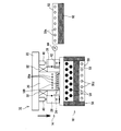
- the control unit 18 first lowers the upper unit 14 or places the mounting table 12 as shown in FIG. 3. And the bottom surface of the side mold 28 is brought into close contact with the mounting table 12. At this time, the control unit 18 applies air pressure to the air cylinder 40 and extends it so that the upper mold 20 and the interposition pad 24 do not contact the workpiece 100, and the side mold 28 is positioned below the upper mold 20 and the like. Leave it protruding. At this time, the lower heating mold 50 and the lower cooling mold 52 are both separated from the mounting table 12. Accordingly, in this state, no pressure is applied to the workpiece 100.
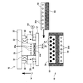
- the control unit 18 releases the pressure of the air cylinder 40 and allows the air cylinder 40 to contract.
- the air cylinder 40 can be contracted, the upper mold 20 and the side mold 28 are relatively moved toward the mounting table 12 by the vacuum pressure (due to a pressure difference between the sealed space and the external space).
- the interposing pad 24 comes into contact with the workpiece 100, and the workpiece 100 is pre-pressurized with a load Pb corresponding to the vacuum pressure.
- the pre-pressurization load Pb is sufficiently lower than the press load Pp applied by the main pressurization described later.
- this pre-pressurization is performed in a state where the mounting table 12 and the heating lower mold 50 are separated from each other.
- the pre-pressurization is performed in a state before the workpiece 100 is not heated and the adhesive 114 is softened.
- the intervening pad 24 is deformed according to the surface shape of the workpiece 100, wraps around the workpiece 100, particularly around the adhesive 114 before softening, and Hold the workpiece 100.
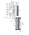
- the control unit 18 lowers the upper unit 14 on which the mounting table 12 is vacuum-adsorbed as shown in FIG.
- the main pressurization for pressing the mounting table 12 from the lower side with the lower die 50 for heating is performed.
- the workpiece 100 is sandwiched between the upper mold 20 and the heating lower mold 50 and is pressed with a prescribed press load Pp.
- the lower heating mold 50 is heated in advance to a predetermined processing temperature Tp. The heat of the lower mold 50 for heating is transmitted to the workpiece 100 through the mounting table 12 having excellent heat conductivity.
- the workpiece 100 is heated to a predetermined processing temperature Tp while being pressed with a predetermined press load Pp.
- the thermosetting adhesive 114 provided on the workpiece 100 reaches the glass transition temperature Tg and softens, and then reaches the curing temperature Tc and is cured. .
- the electronic component 112 and the substrate 110 are bonded.
- the heat of the lower heating mold 50 is also transmitted to the interposing pad 24 via the mounting table 12 and the workpiece 100.
- the heat insulating layer 36 is provided in the lower part of the intervening pad 24, heat is not easily transmitted to the flexible layer 34, and the flexible layer 34 and the upper mold 20 positioned on the flexible layer 34 may become excessively hot. It is prevented.
- the control unit 18 raises the upper unit 14 and separates the heating lower mold 50 from the mounting table 12 as shown in FIG. If a sufficient space can be formed between the lower heating mold 50 and the mounting table 12, the control unit 18 places the lower cooling mold 52 between the mounting table 12 and the lower heating mold 50 as shown in FIG. 7. Deploy. In this state, the upper unit 14 is lowered together with the mounting table 12, and the workpiece 100 is pressurized with a prescribed cooling load Pc. At this time, since the cooling lower mold 52 is cooled in advance by the refrigerant, the workpiece 100 can be rapidly cooled.
- the control unit 18 raises the upper unit 14 together with the mounting table 12 to release the pressure. Further, the control unit 18 applies pressure to the air cylinder 40 to extend the air cylinder 40, thereby raising the upper mold 20 and separating the interposition pad 24 and the workpiece 100. Further, the suction hole 42 is released to the atmosphere, and the sealed space is set to atmospheric pressure. Finally, when the upper unit 14 is further raised and the upper mold 20 unit is separated from the mounting table 12, the mounting table 12 is transported to a predetermined unloading position (not shown).
- FIG. 8 is a graph showing an example of changes in the pressure of the surrounding environment of the workpiece 100, the temperature of the workpiece 100, and the load applied to the workpiece 100 during execution of the pressurizing process.
- the pressure in the surrounding environment of the workpiece 100 is the atmospheric pressure Pa at the start of the pressurizing process (time t0).
- the temperature of the workpiece 100 is normal temperature Tn and the pressing force is zero.
- the workpiece 100 is pressurized with a predetermined press load Pp at time t4.
- This press load Pp is large enough to obtain conduction between the bump 113 of the electronic component 112 and the wiring of the substrate 110, and is, for example, 20 tons.
- the main pressurization is terminated. That is, at time t ⁇ b> 5, the control unit 18 raises the upper unit 14 to release the pressurization of the workpiece 100.
- the control unit 18 presses and cools the workpiece 100 with the cooling lower mold 52 instead of the heating lower mold 50.
- the cooling lower mold 52 comes into contact with the mounting table 12 at time t6
- the temperature of the workpiece 100 is rapidly decreased.
- the pressing force of the workpiece 100 is also increased, and deformation such as warpage of the workpiece 100 is effectively prevented.
- the cooling load Pc applied at this time is, for example, about 10 tons.
- control unit 18 raises the upper unit 14 to release the pressurization of the workpiece 100. After that, the atmospheric pressure is released around the workpiece 100. At time t8, when the periphery of the workpiece 100 returns to the atmospheric pressure, the upper unit 14 is separated from the workpiece 100, and the workpiece 100 is transported to the discharge position together with the mounting table 12.
- the lower mold that contributes to the pressurization of the workpiece 100 is composed of a heating lower mold 50 preheated and a cooling lower mold 52 cooled in advance. Switching. The reason for this configuration will be described in comparison with the prior art.
- the workpiece 100 is sandwiched between the upper die 20 and the lower die, and the workpiece 100 is heated or cooled as necessary.
- both the heating means and the cooling means are provided inside the lower mold, and the lower mold is heated and cooled as necessary.
- a time for heating the cooled lower mold to the predetermined processing temperature Tp and a time for cooling the heated lower mold to the predetermined cooling temperature are required.
- the processing time is prolonged.
- the lower mold in order to withstand a high pressure, the lower mold has to have a large thickness and a large heat capacity. It took time to heat and cool the large lower mold.
- the time required for heating can be shortened by using a heater having a high heating capacity.
- a heater is expensive and causes an increase in cost.
- an overshoot easily exceeding the desired processing temperature Tp is likely to occur in the course of the rise. As a result, the workpiece 100 may be excessively heated although it is temporary.
- the heating lower mold 50 heated in advance and the cooling lower mold 52 cooled in advance are switched according to the progress of the process.
- time for heating or cooling the lower mold is unnecessary, and the workpiece 100 can be heated and cooled quickly. That is, as described with reference to FIG. 8, in this embodiment, if the lower heating mold 50 comes into contact with the mounting table 12 (see around time t ⁇ b> 3 in FIG. 8), the workpiece 100 is quickly heated. If the lower die 52 for cooling is brought into contact with the mounting table 12 (see around time t6 in FIG. 8), the temperature of the workpiece 100 is quickly lowered. In other words, according to the present embodiment, time for heating or cooling the lower mold to a desired temperature is not required. As a result, the time required for the pressure treatment can be greatly reduced.
- the workpiece 100 is heated only from the lower side and is not heated from the upper side.
- the upper mold 20 is not provided with a heating means. Thereby, the workpiece 100 can be heated to a higher temperature than before without increasing the temperature of the interposing pad 24.
- the intervening pad 24 interposed between the upper mold 20 and the workpiece 100 is also heated.
- the intervening pad 24 of the present embodiment has a heat insulating layer 36, but the conventional intervening pad 24 does not have the heat insulating layer 36, and is a flexible layer mainly composed of silicone-based organic matter. It was mainly composed.
- the heat resistant temperature of the flexible layer 34 is often less than 200 degrees.
- the curing temperature Tc of the adhesive 114 provided on the workpiece 100 has increased and is often 150 to 300 degrees. That is, in order to cure the adhesive 114 and bond the electronic component 112 to the substrate 110, the workpiece 100 needs to be heated to 150 to 300 degrees.
- the interposition pad 24 (flexible layer 34) provided between the upper mold 20 and the workpiece 100 is also used. Will be heated. In this case, the interposing pad 24 may exceed the heat resistance temperature and may be damaged. That is, in the conventional pressurizing apparatus 10 in which the heating means is provided in the upper mold 20, the intervening pad 24 may be damaged. Therefore, in the conventional pressure device 10 in which the upper die 20 is provided with heating means, the workpiece 100 cannot be heated to a temperature higher than the heat resistance temperature of the intervening pad 24 (flexible layer 34).
- the heating means is provided only in the lower mold 50 for heating, and the upper mold 20 is not provided with the heating means. Therefore, the flexible layer 34 having low heat resistance is not heated from the upper mold 20.
- the heat insulation layer 36 is provided between the flexible layer 34 with low heat resistance, and the workpiece 100 heated to high temperature.
- the upper mold 20 is maintained at a constant temperature by flowing a refrigerant through the refrigerant flow path 30a. As a result, heat transfer to the flexible layer 34 is effectively prevented, and the temperature rise of the flexible layer 34 and consequently thermal damage can be effectively prevented.
- the workpiece 100 can be heated to a temperature higher than the heat-resistant temperature of the flexible layer 34, and the range of the workpiece 100 that can be handled is expanded.
- the surrounding environment of the workpiece is vacuumed prior to heating the workpiece 100.
- vacuum suction is preferably performed before the adhesive melts, that is, before the adhesive 114 reaches the glass transition temperature Tg.
- the adhesive 114 is melted and the air cannot be properly vented because the high temperature upper die 20 is close to the workpiece 100 during vacuum suction.
- heating of the upper mold 20 is stopped at the time of vacuum suction. In this case, however, the upper mold 20 needs to be heated after the vacuum suction, and the time required for processing is reduced. There was a problem of prolonged.
- pre-pressurization is performed by pressing the workpiece with the upper mold 20 and the intervening pad 24 with a pre-load Pb lower than the press load Pp. ing.
- pre-pressurizing before heating, the workpiece 100 is held by the interposing pad 24.
- the conventional pressurizing apparatus 10 pressurizes and heats the workpiece 100 without performing preliminary pressurization. Therefore, the adhesive 114 may reach the glass transition temperature Tg and soften before the workpiece 100 is sufficiently held by the intervening pad 24.
- the adhesive 114 is softened in a state where it is not held by the intervening pad 24, the electronic component 112 can move relatively freely.
- the workpiece 100 is pre-pressurized with the unheated upper mold 20 and the intervening pad 24, the workpiece 100 is held by the intervening pad 24, and then the workpiece 100 is heated. Is going. For this reason, even if the adhesive is softened by heating, the movement of the electronic component 112 is restricted, and displacement of the electronic component 112 can be effectively prevented.
- FIGS. 9 to 12 are diagrams showing the flow of the pressurizing process in the second embodiment.
- the second embodiment is different from the first embodiment in that both the lower heating mold 50 and the lower cooling mold 52 can move horizontally.
- FIG. 9 shows the start of the pressurizing process in the second embodiment.
- the cooling lower mold 52 is located at a position shifted in the horizontal direction with respect to the upper mold 20, and the heating lower mold 50 is located below the upper mold 20.
- the mounting table 12 on which the workpiece 100 is mounted is conveyed onto the cooling lower mold 52.
- cooling lower mold 52 since the cooling lower mold 52 is in a position shifted in the horizontal direction from the upper mold 20, a large space can be secured above the cooling lower mold 52, and a space for transporting the mounting table 12 (for example, mounting) A sufficient installation space for the mechanism for transporting the mounting table 12 can be secured.
- the control unit 18 then moves the heating lower mold 50 to a position shifted in the horizontal direction from the upper mold 20, as shown in FIG. Let At the same time, the control unit 18 horizontally moves the cooling lower mold 52 to a position directly below the upper mold 20. Thereafter, the upper unit 14 is lowered to bring the bottom surface of the side mold 28 into close contact with the upper surface of the mounting table 12. After that, similarly to the first embodiment, after vacuuming the sealed space around the workpiece 100, the workpiece is preliminarily reserved with the preload Pb using the pressure difference between the sealed space and the external space. Pressurize.
- the control unit 18 again moves the lower cooling mold 52 to a position shifted in the horizontal direction from the upper mold 20 and moves the lower heating mold 50 to a position directly below the upper mold 20.
- the main pressurization is performed in which the mounting table 12 is pressed by the lower heating mold 50 to heat the workpiece 100 while pressing the workpiece 100 with a predetermined press load Pp.
- the lower mold 50 for heating and the lower mold 52 for cooling are exchanged, and the workpiece 100 is cooled while being pressurized with the lower mold 52 for cooling.
- the upper unit 14 When the cooling of the workpiece 100 is completed, the upper unit 14 is raised, the upper unit 14 and the mounting table 12 are separated from each other, and then the cooling lower mold 52 on which the mounting table 12 is mounted is horizontally disposed. Move in the direction. Thereafter, the mounting table 12 is transported to a predetermined discharge position.
- the lower mold 50 for heating and the lower mold 52 for cooling do not line up and down. , 52 is prevented from transferring heat. As a result, it becomes easy to keep the lower dies 50 and 52 at a specified temperature.
- the time required for heating and cooling, and hence the time for the pressure treatment can be greatly shortened. Further, since vacuum suction and pre-pressurization are performed before the adhesive 114 is softened, it is possible to more reliably prevent air biting and component displacement.
- the configuration described so far is an example, and other configurations can be appropriately changed as long as the lower die contributing to pressurization can be switched between the lower die 50 for heating and the lower die 52 for cooling. May be.
- vacuum suction or preliminary pressurization is performed before the main pressurization, but these may be omitted depending on circumstances.
- the flexible layer 34 and the heat insulating layer 36 are provided on the intervening pad 24.
- the heat insulating layer 36 may be omitted as long as the flexible layer 34 can be kept at a heat resistant temperature or lower. Good.
- the upper unit 14 is moved up and down to switch the execution / release of pressurization.
- the lower unit 16 is moved up and down to pressurize. Execution / cancellation may be switched. Moreover, you may replace the structure of various drive mechanisms, a cooling means, and a heating means with another well-known structure.
Landscapes
- Engineering & Computer Science (AREA)
- Physics & Mathematics (AREA)
- Microelectronics & Electronic Packaging (AREA)
- General Physics & Mathematics (AREA)
- Manufacturing & Machinery (AREA)
- Computer Hardware Design (AREA)
- Condensed Matter Physics & Semiconductors (AREA)
- Power Engineering (AREA)
- Mechanical Engineering (AREA)
- Thermal Sciences (AREA)
- Casting Or Compression Moulding Of Plastics Or The Like (AREA)
- Press Drives And Press Lines (AREA)
- Wire Bonding (AREA)
Abstract
Description
Claims (6)
- 被加工物が載置される載置台と、
前記載置台に載置された被加工物を上側から加圧する上型と、
予め加熱手段により加熱されている下型であって、前記上型とともに前記載置台を挟持することで、前記被加工物を加圧しつつ加熱する加熱用下型と、
予め冷却手段により冷却されている下型であって、前記上型とともに前記載置台を挟持することで、前記被加工物を加圧しつつ冷却する冷却用下型と、
前記型の駆動を制御する制御装置であって、前記被加工物の加圧処理の進行状況に応じて、前記被加工物の加圧に寄与する下型を、加熱用下型または冷却用下型に切り替える制御装置と、
を備える、ことを特徴とする加圧装置。 - 請求項1に記載の加圧装置であって、さらに、
前記上型と前記被加工物との間に介在する介在パッドを備え、
前記介在パッドは、
前記被加工物の形状に応じて柔軟に変形する柔軟層と、
前記柔軟層と前記被加工物の間に介在して、前記被加工物と前記柔軟層との間を断熱する断熱層と、
を含む、ことを特徴とする加圧装置。 - 請求項2に記載の加圧装置であって、
前記加熱用下型は、前記被加工物を、前記柔軟層の耐熱温度よりも高い温度に加熱する、ことを特徴とする加圧装置。 - 請求項2または3に記載の加圧装置であって、
前記制御装置は、前記介在パッドを前記被加工物に接触させて前記介在パッドで前記被加工物をホールドした後に、前記加熱用下型による前記被加工物の加熱および加圧を行わせる、ことを特徴とする加圧装置。 - 請求項1から4のいずれか1項に記載の加圧装置であって、さらに、
前記上型の周囲に配され、前記載置台に密着することで、前記上型、載置台とともに前記加工物の周囲に密閉空間を形成するサイド型と、
前記密閉空間内の空気を吸引して、前記被加工物の周囲を真空状態にする吸引装置と、
を備え、
前記制御装置は、前記被加工物の加圧に先だって、前記サイド型を前記載置台に接触させて前記密閉空間を形成するとともに、前記吸引装置を駆動して前記密閉空間を真空状態にする、
ことを特徴とする加圧装置。 - 載置台に載置された被加工物を加圧および加熱する加圧方法であって、
上型と、予め加熱手段により加熱された加熱用下型と、で前記被加工物が載置された載置台を挟持して前記被加工物を加圧するとともに、前記加熱用下型からの熱で前記被加工物を加熱する加熱ステップと、
前記上型と、予め冷却手段により冷却された冷却用下型と、で前記載置台を挟持して前記被加工物を加圧するとともに、前記被加工物を冷却する冷却ステップと、
を含むことを特徴とする加圧方法。
Priority Applications (7)
| Application Number | Priority Date | Filing Date | Title |
|---|---|---|---|
| CN202210370580.8A CN114559672B (zh) | 2016-04-27 | 2017-02-14 | 加压装置及加压方法 |
| CN201780024998.0A CN109075087B (zh) | 2016-04-27 | 2017-02-14 | 加压装置及加压方法 |
| EP21208859.5A EP3975230B1 (en) | 2016-04-27 | 2017-02-14 | Pressurizing device and pressurizing method |
| EP17789010.0A EP3451368B1 (en) | 2016-04-27 | 2017-02-14 | Pressurizing device and pressurizing method |
| KR1020187032599A KR20180135465A (ko) | 2016-04-27 | 2017-02-14 | 가압 장치 및 가압 방법 |
| US16/095,987 US11037790B2 (en) | 2016-04-27 | 2017-02-14 | Pressurizing device and pressurizing method |
| US17/024,230 US11901199B2 (en) | 2016-04-27 | 2020-09-17 | Pressurizing device and pressurizing method |
Applications Claiming Priority (2)
| Application Number | Priority Date | Filing Date | Title |
|---|---|---|---|
| JP2016-089812 | 2016-04-27 | ||
| JP2016089812A JP6181807B1 (ja) | 2016-04-27 | 2016-04-27 | 加圧装置および加圧方法 |
Related Child Applications (2)
| Application Number | Title | Priority Date | Filing Date |
|---|---|---|---|
| US16/095,987 A-371-Of-International US11037790B2 (en) | 2016-04-27 | 2017-02-14 | Pressurizing device and pressurizing method |
| US17/024,230 Continuation US11901199B2 (en) | 2016-04-27 | 2020-09-17 | Pressurizing device and pressurizing method |
Publications (1)
| Publication Number | Publication Date |
|---|---|
| WO2017187721A1 true WO2017187721A1 (ja) | 2017-11-02 |
Family
ID=59605011
Family Applications (1)
| Application Number | Title | Priority Date | Filing Date |
|---|---|---|---|
| PCT/JP2017/005359 WO2017187721A1 (ja) | 2016-04-27 | 2017-02-14 | 加圧装置および加圧方法 |
Country Status (7)
| Country | Link |
|---|---|
| US (2) | US11037790B2 (ja) |
| EP (2) | EP3975230B1 (ja) |
| JP (1) | JP6181807B1 (ja) |
| KR (1) | KR20180135465A (ja) |
| CN (2) | CN114559672B (ja) |
| TW (2) | TWI747669B (ja) |
| WO (1) | WO2017187721A1 (ja) |
Families Citing this family (2)
| Publication number | Priority date | Publication date | Assignee | Title |
|---|---|---|---|---|
| JP6181807B1 (ja) * | 2016-04-27 | 2017-08-16 | 日機装株式会社 | 加圧装置および加圧方法 |
| TWI849872B (zh) * | 2023-04-27 | 2024-07-21 | 友達光電股份有限公司 | 加壓機構 |
Citations (3)
| Publication number | Priority date | Publication date | Assignee | Title |
|---|---|---|---|---|
| JP2004058349A (ja) * | 2002-07-26 | 2004-02-26 | Meiki Co Ltd | 積層装置および積層方法 |
| JP2010062468A (ja) * | 2008-09-05 | 2010-03-18 | Denso Corp | 多層基板の製造方法 |
| JP2010287691A (ja) * | 2009-06-10 | 2010-12-24 | Nikon Corp | 重ね合わせ装置、位置合わせ装置および基板貼り合わせ装置 |
Family Cites Families (27)
| Publication number | Priority date | Publication date | Assignee | Title |
|---|---|---|---|---|
| US4490321A (en) * | 1982-12-16 | 1984-12-25 | Klinkau & Co. Gmbh | Method and apparatus for manufacturing filter plates or the like |
| DE3509119A1 (de) * | 1985-03-14 | 1986-09-18 | WIRSBO PEX Platzer Schwedenbau GmbH, 6056 Heusenstamm | Verfahren zur verarbeitung von halbzeug aus vernetzten kunststoffen |
| US7153467B2 (en) * | 1995-06-07 | 2006-12-26 | Acushnet Company | Method of making a golf ball with a multi-layer core |
| US5712032A (en) * | 1995-11-21 | 1998-01-27 | Armstrong World Industries, Inc. | Patterned heat welding rod for seaming resilient flooring |
| JP2001338446A (ja) * | 2000-05-24 | 2001-12-07 | Sony Corp | 光学式記録媒体の製造装置及び光学式記録媒体の製造方法 |
| US9332992B2 (en) * | 2004-08-05 | 2016-05-10 | Cardiokinetix, Inc. | Method for making a laminar ventricular partitioning device |
| KR100889283B1 (ko) | 2001-09-12 | 2009-03-17 | 니기소 가부시키가이샤 | 회로소자의 실장방법 및 가압장치 |
| JP4718734B2 (ja) * | 2001-09-12 | 2011-07-06 | 日機装株式会社 | 回路素子の実装方法 |
| JP3931330B2 (ja) * | 2001-09-14 | 2007-06-13 | ソニー株式会社 | 熱プレス用プレートおよびカード製造装置 |
| JP3472963B1 (ja) * | 2002-05-30 | 2003-12-02 | ミカドテクノス株式会社 | 高温用真空プレス装置 |
| JP4059008B2 (ja) | 2002-06-04 | 2008-03-12 | 富士電機デバイステクノロジー株式会社 | プレス成形方法およびプレス成形装置 |
| JP4607429B2 (ja) | 2003-03-25 | 2011-01-05 | 東レ・ダウコーニング株式会社 | 半導体装置の製造方法および半導体装置 |
| JP3949072B2 (ja) | 2003-03-26 | 2007-07-25 | 日機装株式会社 | 加圧装置 |
| JP3975969B2 (ja) | 2003-05-16 | 2007-09-12 | カシオ計算機株式会社 | ドライフィルムレジストのラミネート方法 |
| JP2005072369A (ja) | 2003-08-26 | 2005-03-17 | Fuji Electric Holdings Co Ltd | 半導体装置の製造方法 |
| JP4763356B2 (ja) | 2005-06-23 | 2011-08-31 | 日機装株式会社 | 加圧装置およびヒータユニット |
| US20090289097A1 (en) * | 2008-05-21 | 2009-11-26 | Weng-Jin Wu | Wafer Leveling-Bonding System Using Disposable Foils |
| JP5302804B2 (ja) | 2009-07-16 | 2013-10-02 | 株式会社神戸製鋼所 | 金型加熱装置 |
| BR112012017859A2 (pt) * | 2010-01-18 | 2017-06-20 | Polyworks Inc | "sistema de moldagem, método e artigos formados por ele" |
| JP5447110B2 (ja) | 2010-04-06 | 2014-03-19 | 株式会社ニコン | 基板貼り合わせ装置、積層半導体の製造方法、積層半導体及び基板貼り合わせ方法 |
| TWI404638B (zh) * | 2011-03-16 | 2013-08-11 | Wistron Corp | 利用超臨界流體轉印薄膜至工件之方法與轉印系統 |
| JP5934801B2 (ja) * | 2012-09-28 | 2016-06-15 | 東芝機械株式会社 | 成形装置 |
| JP5376038B1 (ja) * | 2012-11-05 | 2013-12-25 | オムロン株式会社 | 転写成形装置 |
| JP6050103B2 (ja) * | 2012-11-29 | 2016-12-21 | ミカド機器販売株式会社 | 真空加熱加圧封止成形装置及び真空加熱加圧封止成形方法 |
| JP2015076553A (ja) * | 2013-10-10 | 2015-04-20 | 日東電工株式会社 | 電子デバイスパッケージの製造方法及び電子デバイスの封止方法 |
| TW201516007A (zh) * | 2013-10-22 | 2015-05-01 | Weis Ltd | 玻璃模造成型方法及應用該玻璃模造成型方法的設備 |
| JP6181807B1 (ja) * | 2016-04-27 | 2017-08-16 | 日機装株式会社 | 加圧装置および加圧方法 |
-
2016
- 2016-04-27 JP JP2016089812A patent/JP6181807B1/ja active Active
-
2017
- 2017-02-14 US US16/095,987 patent/US11037790B2/en active Active
- 2017-02-14 KR KR1020187032599A patent/KR20180135465A/ko not_active Application Discontinuation
- 2017-02-14 CN CN202210370580.8A patent/CN114559672B/zh active Active
- 2017-02-14 EP EP21208859.5A patent/EP3975230B1/en active Active
- 2017-02-14 EP EP17789010.0A patent/EP3451368B1/en active Active
- 2017-02-14 WO PCT/JP2017/005359 patent/WO2017187721A1/ja active Application Filing
- 2017-02-14 CN CN201780024998.0A patent/CN109075087B/zh active Active
- 2017-03-23 TW TW109144734A patent/TWI747669B/zh active
- 2017-03-23 TW TW106109647A patent/TWI716568B/zh active
-
2020
- 2020-09-17 US US17/024,230 patent/US11901199B2/en active Active
Patent Citations (3)
| Publication number | Priority date | Publication date | Assignee | Title |
|---|---|---|---|---|
| JP2004058349A (ja) * | 2002-07-26 | 2004-02-26 | Meiki Co Ltd | 積層装置および積層方法 |
| JP2010062468A (ja) * | 2008-09-05 | 2010-03-18 | Denso Corp | 多層基板の製造方法 |
| JP2010287691A (ja) * | 2009-06-10 | 2010-12-24 | Nikon Corp | 重ね合わせ装置、位置合わせ装置および基板貼り合わせ装置 |
Non-Patent Citations (1)
| Title |
|---|
| See also references of EP3451368A4 * |
Also Published As
| Publication number | Publication date |
|---|---|
| EP3451368A4 (en) | 2019-11-27 |
| CN114559672A (zh) | 2022-05-31 |
| EP3451368A1 (en) | 2019-03-06 |
| TW202124129A (zh) | 2021-07-01 |
| EP3975230B1 (en) | 2023-06-14 |
| CN109075087A (zh) | 2018-12-21 |
| CN109075087B (zh) | 2022-04-29 |
| TWI747669B (zh) | 2021-11-21 |
| EP3451368B1 (en) | 2021-12-29 |
| TW201738075A (zh) | 2017-11-01 |
| KR20180135465A (ko) | 2018-12-20 |
| JP6181807B1 (ja) | 2017-08-16 |
| US11037790B2 (en) | 2021-06-15 |
| US11901199B2 (en) | 2024-02-13 |
| EP3975230A1 (en) | 2022-03-30 |
| US20210028018A1 (en) | 2021-01-28 |
| CN114559672B (zh) | 2024-04-02 |
| US20190139769A1 (en) | 2019-05-09 |
| TWI716568B (zh) | 2021-01-21 |
| JP2017199812A (ja) | 2017-11-02 |
Similar Documents
| Publication | Publication Date | Title |
|---|---|---|
| US9161485B2 (en) | System and method for microelectronics lamination press | |
| KR20120109963A (ko) | 접합장치 및 접합방법 | |
| WO2003094222A1 (fr) | Procede de collage et dispositif de collage | |
| JP6234277B2 (ja) | 圧着ヘッド、それを用いた実装装置および実装方法 | |
| TW201735194A (zh) | 半導體安裝設備、半導體安裝設備頭、及用於製造層疊式晶片之方法 | |
| US11901199B2 (en) | Pressurizing device and pressurizing method | |
| KR20160149000A (ko) | 진공 라미네이터 및 진공 라미네이팅 방법 | |
| JP6336510B2 (ja) | 加圧方法および加圧装置 | |
| KR20130096133A (ko) | 라미네이팅 장치 | |
| JP7268929B2 (ja) | 実装装置及び実装方法 | |
| TWM607461U (zh) | 壓合上治具之加熱裝置 | |
| KR102372519B1 (ko) | 실장 장치 | |
| JP2001345355A (ja) | サポートフレーム貼付装置 | |
| CN108666230B (zh) | 用于电子产品的整平设备 | |
| JP2002355835A (ja) | 熱伝導性基板の製造方法 | |
| JP5892686B2 (ja) | 圧着装置および温度制御方法 | |
| JP6461822B2 (ja) | 半導体装置の実装方法および実装装置 | |
| JPH10175229A (ja) | 真空積層装置 |
Legal Events
| Date | Code | Title | Description |
|---|---|---|---|
| NENP | Non-entry into the national phase |
Ref country code: DE |
|
| ENP | Entry into the national phase |
Ref document number: 20187032599 Country of ref document: KR Kind code of ref document: A |
|
| WWE | Wipo information: entry into national phase |
Ref document number: 2017789010 Country of ref document: EP |
|
| ENP | Entry into the national phase |
Ref document number: 2017789010 Country of ref document: EP Effective date: 20181127 |
|
| 121 | Ep: the epo has been informed by wipo that ep was designated in this application |
Ref document number: 17789010 Country of ref document: EP Kind code of ref document: A1 |