WO2021124799A1 - ガラス板の製造方法及びガラス板梱包体 - Google Patents
ガラス板の製造方法及びガラス板梱包体 Download PDFInfo
- Publication number
- WO2021124799A1 WO2021124799A1 PCT/JP2020/043432 JP2020043432W WO2021124799A1 WO 2021124799 A1 WO2021124799 A1 WO 2021124799A1 JP 2020043432 W JP2020043432 W JP 2020043432W WO 2021124799 A1 WO2021124799 A1 WO 2021124799A1
- Authority
- WO
- WIPO (PCT)
- Prior art keywords
- protective sheet
- glass
- plate
- glass plate
- original plate
- Prior art date
- Legal status (The legal status is an assumption and is not a legal conclusion. Google has not performed a legal analysis and makes no representation as to the accuracy of the status listed.)
- Ceased
Links
Images






Classifications
-
- B—PERFORMING OPERATIONS; TRANSPORTING
- B26—HAND CUTTING TOOLS; CUTTING; SEVERING
- B26F—PERFORATING; PUNCHING; CUTTING-OUT; STAMPING-OUT; SEVERING BY MEANS OTHER THAN CUTTING
- B26F3/00—Severing by means other than cutting; Apparatus therefor
-
- B—PERFORMING OPERATIONS; TRANSPORTING
- B28—WORKING CEMENT, CLAY, OR STONE
- B28D—WORKING STONE OR STONE-LIKE MATERIALS
- B28D5/00—Fine working of gems, jewels, crystals, e.g. of semiconductor material; apparatus or devices therefor
-
- B—PERFORMING OPERATIONS; TRANSPORTING
- B28—WORKING CEMENT, CLAY, OR STONE
- B28D—WORKING STONE OR STONE-LIKE MATERIALS
- B28D7/00—Accessories specially adapted for use with machines or devices of the preceding groups
- B28D7/04—Accessories specially adapted for use with machines or devices of the preceding groups for supporting or holding work or conveying or discharging work
-
- B—PERFORMING OPERATIONS; TRANSPORTING
- B65—CONVEYING; PACKING; STORING; HANDLING THIN OR FILAMENTARY MATERIAL
- B65D—CONTAINERS FOR STORAGE OR TRANSPORT OF ARTICLES OR MATERIALS, e.g. BAGS, BARRELS, BOTTLES, BOXES, CANS, CARTONS, CRATES, DRUMS, JARS, TANKS, HOPPERS, FORWARDING CONTAINERS; ACCESSORIES, CLOSURES, OR FITTINGS THEREFOR; PACKAGING ELEMENTS; PACKAGES
- B65D7/00—Containers having bodies formed by interconnecting or uniting two or more rigid, or substantially rigid, components made wholly or mainly of metal
- B65D7/02—Containers having bodies formed by interconnecting or uniting two or more rigid, or substantially rigid, components made wholly or mainly of metal characterised by shape
- B65D7/04—Containers having bodies formed by interconnecting or uniting two or more rigid, or substantially rigid, components made wholly or mainly of metal characterised by shape of curved cross-section, e.g. cans of circular or elliptical cross-section
-
- B—PERFORMING OPERATIONS; TRANSPORTING
- B65—CONVEYING; PACKING; STORING; HANDLING THIN OR FILAMENTARY MATERIAL
- B65D—CONTAINERS FOR STORAGE OR TRANSPORT OF ARTICLES OR MATERIALS, e.g. BAGS, BARRELS, BOTTLES, BOXES, CANS, CARTONS, CRATES, DRUMS, JARS, TANKS, HOPPERS, FORWARDING CONTAINERS; ACCESSORIES, CLOSURES, OR FITTINGS THEREFOR; PACKAGING ELEMENTS; PACKAGES
- B65D85/00—Containers, packaging elements or packages, specially adapted for particular articles or materials
- B65D85/30—Containers, packaging elements or packages, specially adapted for particular articles or materials for articles particularly sensitive to damage by shock or pressure
- B65D85/48—Containers, packaging elements or packages, specially adapted for particular articles or materials for articles particularly sensitive to damage by shock or pressure for glass sheets
-
- C—CHEMISTRY; METALLURGY
- C03—GLASS; MINERAL OR SLAG WOOL
- C03B—MANUFACTURE, SHAPING, OR SUPPLEMENTARY PROCESSES
- C03B33/00—Severing cooled glass
- C03B33/02—Cutting or splitting sheet glass or ribbons; Apparatus or machines therefor
- C03B33/023—Cutting or splitting sheet glass or ribbons; Apparatus or machines therefor the sheet or ribbon being in a horizontal position
Definitions
- the present invention improves the form of the protective sheet when the glass original plate is laminated on the protective sheet, and the protective sheet in the glass plate package having a laminated body in which the protective sheet and the glass original plate are alternately arranged. Regarding the improvement of the form of.
- Patent Document 1 discloses that a glass plate (glass original plate) and a protective sheet are alternately arranged in a vertical posture (tilted posture).
- both ends in the width direction of the glass original plate may be cut as unnecessary parts, and the unnecessary parts may be removed from the protective sheet after cutting.
- Patent Document 1 in the laminate composed of the glass original plate in the vertical posture and the protective sheet, the upper end and both ends in the width direction of the protective sheet protrude from both upper corners of the glass original plate. Then, the cutting operation disclosed in Patent Document 2 is performed by taking out both of them as they are from such a laminated body and converting the postures of both into a flat posture.
- one corner of the original glass plate (glass original plate in a vertical posture)
- the upper corner of the surface) may pierce the protective sheet. Therefore, when the original glass plate is broken along the scribe line, smooth work is hindered by the catching of the corner portion on one side of the original glass plate and the protective sheet. Furthermore, when the unnecessary part is lifted from the protective sheet and removed by a holding tool such as a suction pad or a gripping member after folding, the corner part of the unnecessary part is caught by the protective sheet, so that the unnecessary part falls off from the holding tool.
- the unnecessary portion may be unreasonably deformed and damaged due to the above-mentioned catching.
- the glass powder falls and adheres to the glass plate as a product, which not only deteriorates the quality of the glass plate but also causes the generation of defective products.
- the present invention provides a catch between the original glass plate and the protective sheet when performing various operations on the original glass plate after taking them out from the laminated body in which the original glass plate and the protective sheet are alternately arranged in a vertical posture.
- the task is to make it difficult to occur and to facilitate various operations.
- the first aspect of the present invention which was devised to solve the above problems, is a preparatory step of preparing a laminated body in which a glass original plate and a protective sheet are alternately arranged in a vertical position, and after the preparatory step, the above-mentioned After the taking-out step of taking out the glass original plate and the protective sheet from the laminated body and the taking-out step, the glass original plate is cut into a glass plate in a state where the glass original plate is laid flat on the protective sheet.
- a method for manufacturing a glass plate comprising a cutting step of dividing into unnecessary portions and a removing step of removing the unnecessary portions from the protective sheet after the cutting step.
- the protective sheet is provided.
- the form on one side is such that the corner portion on one side of the glass original plate is projected from the protective sheet, and the glass original plate and the protective sheet are in the vertical posture on the one side. It is characterized by being above both of them when they were there.
- both of the set taken out from the laminated body in which the glass original plate and the protective sheet are alternately arranged in the vertical posture are put in a flat posture and the cutting process is executed.
- this cutting step is executed, since the corner portion on one side of the original glass plate protrudes from the protective sheet, the situation where the corner portion on one side of the original glass plate sticks into the protective sheet is avoided.
- the "one side” here means the upper side of both the original glass plate and the protective sheet when they are laminated in a vertical position. In this case, even if the cutting work performed in the cutting step is a work that causes bending deformation of the glass original plate such as folding, the glass original plate is prevented from being caught on the protective sheet on one side thereof. The cutting work is facilitated.
- the removing step after the cutting step for example, the work of lifting and removing the unnecessary portion by a holding tool such as a suction pad or a gripping member is performed. Also in this case, the corner portion on one side of the unnecessary portion (the portion that was the corner portion on one side of the glass original plate) is prevented from being caught by the protective sheet. As a result, it is possible to prevent the unnecessary portion from falling off from the holder, the unnecessary portion from being damaged due to unreasonable deformation, and the glass powder from adhering to the glass plate as a product. As a result, inefficient interruption of work in the cutting process and the removing process is prevented, and deterioration of the quality of the glass plate as a product and the occurrence of defective products are suppressed.
- a holding tool such as a suction pad or a gripping member
- the upper corner portion of the protective sheet may be cut off to manufacture the protective sheet to be used in the cutting step.
- the form of the one side of the protective sheet used in the cutting step may be a form in which one corner of the product area of the glass original plate is projected from the protective sheet. Good.
- the form of the other side of the protective sheet is such that the corner portion of the other side of the glass original plate is projected from the protective sheet, and the other side is formed.
- the glass original plate and the protective sheet may be on the lower side of both of them when they are in the vertical posture.
- the lower corner portion of the protective sheet may be cut off to manufacture the protective sheet to be used in the cutting step.
- the form of the protective sheet used in the cutting step on the other side may be a form in which the corner portion on the other side of the product region of the glass original plate is squeezed out from the protective sheet. Good.
- the glass plate is placed in a flat position on the protective sheet used in the cutting step in the above-mentioned method for manufacturing a glass plate in place of the original glass plate.
- the protective sheet is separated from the front end of the glass plate in the transport direction by transporting both of them with one side as the front side in the transport direction and changing the traveling directions of the two in the middle of the transport.
- a separation step for separating the two may be provided.
- the work of separating the protective sheet from the glass plate can be smoothly performed. That is, when transporting the glass plates in a state of being stacked on the protective sheet, if a situation occurs in which the front corner of the glass plate in the transport direction pierces the protective sheet, the traveling directions of the two are changed during the transport. Even so, a situation may occur in which the glass plate and the protective sheet move in the same direction. As a result, the protective sheet cannot be separated from the glass plate, which may cause problems such as damage to the glass plate.
- the form of the protective sheet on the front side in the transport direction in the method here is a form in which the corner portion on the front side in the transport direction of the glass original plate is protruded.
- the glass original plate cannot be pierced into the protective sheet.
- the above corners of the glass original plate and the above corners of the glass plate are only different in position by the amount of removal of unnecessary portions. Therefore, the above-mentioned piercing is unlikely or less likely to occur in the glass plate, which can contribute to facilitating the work of separating the protective sheet from the glass plate.
- the second aspect of the present invention which was devised to solve the above problems, is a glass plate packing body in which a laminated body in which glass original plates and protective sheets are alternately arranged in a vertical position is loaded on a packing pallet.
- the upper form of the protective sheet is characterized in that the upper corner portion of the glass original plate is projected from the protective sheet.
- the protective sheet and the original glass plate are taken out as they are, and after converting both of them from the vertical posture to the flat posture, the glass original plate is cut and unnecessary parts are removed from the protective sheet. It can be performed. As a result, one corner of the original glass plate does not stick to the protective sheet, and the same advantages as described above can be obtained. Further, if the upper side of the protective sheet and the glass original plate is the front side in the transport direction, the work of separating the protective sheet from the glass plate can be smoothly performed.
- the present invention when performing various operations on the glass original plate after taking out the original glass plate and the protective sheet from the laminated body in which the original glass plate and the protective sheet are alternately arranged in a vertical posture, it is difficult for the two to be caught. Therefore, various operations can be facilitated.
- the method for manufacturing a glass plate includes a preparatory step 1 for preparing a laminate in which a glass original plate and a protective sheet are alternately arranged on a packing pallet in a vertical posture, and a lamination step 1. It includes a take-out step 2 of taking out the glass original plate and the protective sheet from the body. Further, this manufacturing method includes a cutting step 3 of cutting the glass original plate in a state where the original glass plate is placed flat on the taken-out protective sheet and dividing the glass original plate into unnecessary parts, and unnecessary from the protective sheet. The removal step 4 for removing the portion and the separation step 5 for separating the protective sheet from the glass plate are provided.
- FIG. 2 is a schematic side view illustrating the glass plate packing body 6 prepared in the preparation step 1
- FIG. 3a is a schematic front view cut along the line AA of FIG.
- the glass original plate 7 is obtained by cutting a glass ribbon formed by a down draw method (for example, an overflow down draw method) or a float method along the width direction.
- a down draw method for example, an overflow down draw method
- a float method along the width direction.
- both end portions 7a of the glass original plate 7 in the width direction are unnecessary portions. Both end portions 7a are separated from the product region 7b by cutting the glass original plate 7 along the planned cutting line 7c in the cutting step 3.
- the glass original plate 7 preferably has a plate thickness of 100 to 2000 ⁇ m, and the length of each side is preferably 1500 to 4000 mm.
- the protective sheet 8 preferably has a thickness of 100 to 500 ⁇ m, and the material is preferably a foamed resin sheet such as polyethylene or a non-foamed resin sheet.
- the protective sheet 8 and the glass original plate 7 will be described.
- the protective sheet 8 and the glass original plate 7 shown in FIGS. 3a to 6b are designated by the same reference numerals with respect to common components. Detailed description of the components with the same reference numerals will be omitted.
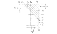
- the protective sheet 8 shown in FIG. 3a has a shape in which the upper side squeezes out both corners 7d on the upper side of the glass original plate 7. More specifically, the protective sheet 8 has a rectangle as a basic shape, and both corners on the upper side of the rectangle are omitted.
- the upper corner portion 7d of the rectangular glass original plate 7 protrudes from the missing edge 8a on the upper side of the protective sheet 8.
- the protrusion dimension L1 is preferably 5 to 20 mm. In this case, the upper corner portion 7d of the glass original plate 7 fits in the missing portion (the portion shaded by the parallel diagonal line of the alternate long and short dash line) 8b of the protective sheet 8 shown in FIG. Not reached.
- the upper end portion 8d and the widthwise both end portions 8e of the protective sheet 8 protrude from the upper side 7e of the glass original plate 7 and the side portions 7f on both sides in the width direction, respectively.
- the protrusion dimension L2 from the upper side 7e is preferably 50 to 150 mm
- the protrusion dimension L3 from the sides 7f on both sides in the width direction is preferably 50 to 200 mm.
- the corner portion (upper corner portion of the product area 7b) formed by the upper side 7e of the glass original plate 7 and the planned cutting line 7c protrudes from the missing edge 8a on the upper side of the protective sheet 8. Absent.
- the separation dimension L4 from the top of the corner portion 7g to the edge edge 8a is preferably 10 mm or less.
- the lower side 8f of the protective sheet 8 and the lower side 7h of the glass original plate 7 are in contact with or substantially in contact with the mounting surface 10a of the packing pallet 10. They are in the same position or almost in the same position.
- the lower side 8f of the protective sheet 8 is in contact with the mounting surface 10a, and the lower side 7h of the glass original plate 7 is separated upward from the mounting surface 10a.
- the lower end portion including the lower side 8f of the protective sheet 8 protrudes from the lower side 7h of the glass original plate 7.
- the lower side 8f of the protective sheet 8 may be separated upward from the mounting surface 10a, and the lower side 7h of the glass original plate 7 may be in contact with the mounting surface 10a. ..
- the lower end portion including the lower side 7h of the glass original plate 7 may protrude from the lower side 8f of the protective sheet 8.
- the corners of the rectangular protective sheet are cut off to make the corners missing. Therefore, when the glass plate packing body 6 is transported or transported, the entire upper end portion and the entire width direction end portions of the rectangular protective sheet are eaten from the upper side 7e and the width direction side sides 7f of the glass original plate 7, respectively. It will squeeze out. As a result, the entire area of the original glass plate 7 is covered with the protective sheet, and the original glass plate 7 is properly protected.
- the corners of the rectangular protective sheet may be cut off when the take-out step 2 is being executed, or after the take-out step 2 and before the cutting step 3. This excision work may be performed manually by an operator, or may be performed by using a robot hand or the like. Further, when manufacturing the laminated body 9, the protective sheet 8 having missing corners may be used instead of the rectangular protective sheet.
- the missing edge 8a on the upper side of the protective sheet 8 has a shape along a straight line in the example, but may have a wavy shape, a sawtooth shape, an arc shape, or the like.
- the form of the protective sheet 8 is not limited to the above form, and may be the form shown below. That is, in the protective sheet 8 shown in FIG. 4a, not only the upper corners but also the lower corners are omitted.
- the lower end portion of the missing portion (the portion with parallel diagonal lines of the alternate long and short dash line) 8 g is in the vicinity of the lower corner portion 7i of the glass original plate 7. Is located in. Specifically, the lower end 8i of the missing edge 8h on the lower side of the protective sheet 8 coincides with or substantially coincides with the top of the lower corner portion 7i of the glass original plate 7.
- the lower side 8f of the protective sheet 8 is in contact with the mounting surface 10a, and the lower side 7h of the glass original plate 7 is separated upward from the mounting surface 10a, and further, the protective sheet 8 is further separated.
- the lower missing edge 8h is in contact with the top of the lower corner 7i of the glass plate 7.
- the lower side 8f of the protective sheet 8 may be separated upward from the mounting surface 10a, and the lower side 7h of the glass original plate 7 may be in contact with the mounting surface 10a.
- the lower end 8i of the edge 8h of the protective sheet 8 may be in contact with the side 7f on one side in the width direction of the lower end of the glass original plate 7.
- the upper form of the protective sheet 8 is the same as the form shown in FIGS. 3a and 3b. Further, the method for removing the lower corner portion of the protective sheet 8, the timing for removing the corner portion, and the shape of the edge 8h are the same as those already described for the upper corner portion of the protective sheet 8 shown in FIGS. 3a and 3b. It is the same.
- the protective sheet 8 shown in FIG. 5a has a shape in which the upper side squeezes out both corners 7g of the upper side of the product area 7b of the glass original plate 7. Therefore, as shown in FIG. 5b, both the upper corner portion 7d of the glass original plate 7 and the upper corner portion 7g of the product area 7b are provided with the missing portion 8b (parallel diagonal line of the alternate long and short dash line) on the upper side of the protective sheet 8. It fits in the part) and does not reach the outer edge 8c of the missing part 8b.
- the protrusion dimension L5 of the upper corner portion 7g of the product region 7b is preferably 1 to 10 mm. In this case, as shown in FIG.
- the lower side 8f of the protective sheet 8 is in contact with the mounting surface 10a, and the lower side 7h of the glass original plate 7 is separated upward from the mounting surface 10a.
- the lower side 8f of the protective sheet 8 may be separated upward from the mounting surface 10a, and the lower side 7h of the glass original plate 7 may be in contact with the mounting surface 10a.
- the protective sheet 8 does not lack the lower corner portion 8j, but the lower corner portion 8j may be omitted as in the protective sheet 8 shown in FIGS. 4a and 4b. ..
- the method of removing the upper corner of the protective sheet 8, the timing of the removal, and the shape of the edge 8a are the same as those already described for the upper corner of the protective sheet 8 shown in FIGS. 3a and 3b. Is.
- the protective sheet 8 shown in FIG. 6a has a lower form in which both corners 7j on the lower side of the product area 7b of the glass original plate 7 are squeezed out. Therefore, as shown in FIG. 6b, both the lower corner portion 7i of the glass original plate 7 and the lower corner portion 7j of the product area 7b are both the missing portion 8g (parallel to the alternate long and short dash line) on the lower side of the protective sheet 8. It fits in the shaded area) and does not reach the outer edge 8k of the missing part 8g.
- the protrusion dimension L6 of the lower corner portion 7j of the product region 7b from the edge 8h is preferably 1 to 10 mm.
- the lower form of the protective sheet 8 may be a form in which only the lower corner portion 7i of the glass original plate 7 is squeezed out.
- the protrusion dimension of the lower corner portion 7i is preferably 5 to 20 mm
- the separation dimension from the lower corner portion 7i to the edge 8h is preferably 10 mm or less.
- the upper form of the protective sheet 8 is the same as the protective sheet 8 shown in FIGS. 5a and 5b.
- the shape of the upper side of the protective sheet 8 may be the same as that of the protective sheet 8 shown in FIGS. 3a and 3b.
- the lower side 8f of the protective sheet 8 and the lower side 7h of the glass original plate 7 are at the same position or substantially the same position.
- the lower side 8f of the protective sheet 8 is in contact with the mounting surface 10a, and the lower side 7h of the glass original plate 7 is separated upward from the mounting surface 10a.
- the lower side 8f of the protective sheet 8 may be separated upward from the mounting surface 10a, and the lower side 7h of the glass original plate 7 may be in contact with the mounting surface 10a. ..
- the following may be performed. That is, the protective sheet 8 is displaced downward relative to the glass original plate 7 at the time of executing the take-out step 2, or after the take-out step 2 and before the cutting step 3.
- the protective sheet 8 not only the upper side 7e of the glass original plate 7 but also the lower side 7h of the glass original plate 7 is surely covered by the protective sheet 8.
- the "upper side” and “lower side” of the protective sheet 8 and the glass original plate 7 described here mean the upper side and the lower side when the protective sheet 8 and the glass original plate 7 are in the vertical posture.
- the method of removing the lower corner portion of the protective sheet 8 and the shape of the edge 8h are the same as those already described for the upper corner portion of the protective sheet 8 shown in FIGS. 3a and 3b.
- a device capable of holding the glass original plate 7 and the protective sheet 8 as a set for example, a device having a suction pad for sucking and holding both 7 and 8 at the tip, and a device having both 7 and 8 at the tip. It is performed using a device having a gripping member that grips the. Then, these devices take out the glass original plate 7 and the protective sheet 8 from the laminated body 9, change their postures, and put the glass original plate 7 on the protective sheet 8 in a flat posture.
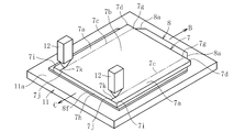
- FIG. 7a and 7b are perspective views illustrating the mode in which the cutting step 3 is executed, respectively.
- the glass original plate 7 is placed on the work surface 11a of the mounting portion 11 in a flat position on the protective sheet 8.
- the mounting portion 11 is composed of, for example, a conveyor, a work pallet on the conveyor, a work surface plate, or the like.
- one side of the glass original plate 7 and the protective sheet 8 indicated by reference numeral B is the upper side of both 7 and 8 when the protective sheet 8 and the glass original plate 7 are in the vertical posture.
- the other side of the glass original plate 7 and the protective sheet 8 indicated by the reference numeral C is the lower side of both the protective sheet 8 and the protective sheet 7 in the vertical posture.
- the glass original plate 7 and the protective sheet 8 here are taken out from the laminated body 9 described with reference to FIGS. 3a and 3b, and the relative positional relationship between the two 7 and 8 is arranged in the laminated body 9. It is in the same state as it was. Therefore, in the example shown in FIG. 7a, the other side 8f of the protective sheet 8 and the other side 7h of the glass original plate 7 are at the same position or substantially the same position. It may be the same. That is, the end portion including the other side side 8f of the protective sheet 8 may protrude from the other side side 7h of the glass plate 7, or the end portion including the other side side 7h of the glass original plate 7 may protrude. It may protrude from the other side 8f of the protective sheet 8.
- FIG. 7a illustrates an embodiment in which a scribe line along the planned cutting line 7c is formed on the surface (upper surface) of the glass original plate 7.
- the scribe wheel 12 is moved along the planned cutting line 7c of the glass original plate 7 to form the scribe line 7k along the planned cutting line 7c.
- the scribe line 7k is formed over the entire length from the other side to the one side of the glass original plate 7.
- the scribe line 7k may be formed at a portion of the original glass plate 7 excluding the other end and the one end.
- the removal step 4 is executed.
- the removing step 4 after holding the unnecessary portion 14 with a holding tool such as a suction pad or a gripping member, the holding tool lifts and moves the unnecessary portion 14 to remove the unnecessary portion 14 from the protective sheet 8.
- the operator may manually remove the unnecessary portion 14 from the protective sheet 8 by using a tool or the like.
- the corner portion 7g on one side of the product region 7b of the glass original plate 7 does not protrude from the missing edge 8a on one side of the protective sheet 8. Therefore, one end of the planned cutting line 7c is supported by the protective sheet 8 from below. Moreover, in the illustrated example, the other end of the planned cutting line 7c is also supported by the protective sheet 8 from below. As a result, when the scribe wheel 12 is moved along the planned cutting line 7c of the glass original plate 7, it is not adversely affected by the step, and the scribe line 7k can be accurately formed.
- the part) and the protective sheet 8 do not get caught.
- the unnecessary portion 14 can be prevented from falling off from the holder, the unnecessary portion 14 being damaged due to an unreasonable deformation, and the glass powder adhering to the glass plate 13.
- inefficient interruption of the work in the cutting step 3 and the removing step 4 is avoided, and the deterioration of the quality of the glass plate 13 and the occurrence of defective products are suppressed.
- since the other side 7h of the glass original plate 7 and the other side 8f of the protective sheet 8 are at the same position, between the other side corner 7i of the glass original plate 7 and the protective sheet 8. Does not get caught.
- FIG. 8 illustrates an embodiment in which the separation step 5 is executed after the removal step 4.
- the conveyor 15 conveys the protective sheet 8 and the glass plate 13 in the direction of arrow D.
- the glass plate 13 still advances in the direction of arrow D and reaches the transfer portion 16 on the front side in the transport direction of the conveyor 15. Will be reprinted.
- the traveling direction of the protective sheet 8 is changed downward by the suction force of the negative pressure.
- the transfer unit 16 is composed of a plurality of rollers 17 arranged along a straight line in the direction of arrow D.
- the protective sheet 8 is formed by a transfer roller 18 arranged at an end portion 15a on the front side in the transfer direction of the transfer conveyor 15 and a portion below the transfer roller 18.
- a negative pressure suction force is applied only to the conveyor.
- the "front side in the transport direction" is one side of the glass original plate 7 in the removal step 4.
- the traveling directions of the glass plate 13 and the protective sheet 8 are different during the transportation in the arrow D direction, so that the protective sheet 8 is separated from the end portion 13a on the front side of the glass plate 13 in the transport direction. To. At this time, if the corner portion 13b (see FIG.
- the glass original plate 7 and the protective sheet 8 are taken out as they are from the laminated body 9 described based on FIGS. 3a and 3b when the cutting step 3 is executed.
- the case of mounting on the working surface 11a of the mounting portion 11 has been given as an example, but other modes as shown below can be exemplified. That is, in the first other example, when the cutting step 3 is executed, both 7 and 8 are taken out as they are from the laminated body 9 described with reference to FIGS. 4a and 4b, and the working surface of the mounting portion 11 is taken out. Place on 11a. In this way, when the glass original plate 7 is broken, the corner portion 7i on the other side and the protective sheet 8 are less likely to be caught. Further, when the unnecessary portion 14 is removed, the corner portion 14b (see FIG. 7b) on the other side and the protective sheet are less likely to be caught.
- both 7 and 8 are taken out from the laminated body 9 described with reference to FIGS. 5a and 5b as they are, and are placed on the working surface 11a of the mounting portion 11. Put it on.
- the corner portion 13b on the front side in the transport direction of the glass plate 13 protrudes from the missing edge 8a on the front side in the transport direction of the protective sheet 8.
- the end portion 13a on the front side in the transport direction of the glass plate 13 is surely prevented from sticking to the protective sheet 8, so that the work of separating the protective sheet 8 from the glass plate 13 can be performed without any trouble.
- the glass original plate 7 and the protective sheet 8 are placed on the working surface 11a of the mounting portion 11 in the manner described based on FIGS. 6a and 6b.
- the same advantages as in the second other example can be obtained when the glass original plate 7 is broken, when the unnecessary portion 14 is removed, and when the protective sheet 8 is separated from the glass plate 13.
- the following advantages are also obtained. That is, when the cutting step 3 and the removing step 4 are executed, not only the corner portion 7d on one side of the glass original plate 7 but also the corner portion 7i on the other side of the glass original plate 7 is surely pierced into the protective sheet 8. Be blocked. In this case, in the embodiment shown in FIGS.
- the protective sheet 8 In the protective sheet 8 according to the above embodiment, a predetermined portion of the protective sheet having a rectangular basic shape is missing, or a predetermined portion of the rectangular protective sheet is cut off, but the shape of the protective sheet 8 Is not limited to this.
- the protective sheet 8 may be formed into a circular shape, an elliptical shape, or another polygonal shape by the chipping or the cutting, and even in such a shape, the corner portion of the glass original plate 7 or the product area 7b may be formed. It is necessary to squeeze out the corners and the corners of the glass plate 13 in the same manner as described above.
- the lower side 8f of the protective sheet 8 is in contact with or substantially in contact with the mounting surface 10a of the packing pallet 10, it may be separated from the mounting surface 10a.
- the lower form of the protective sheet 8 is such that the lower both corners 7i of the glass original plate 7 are squeezed out, and the lower both corners 7j of the product area 7b of the glass original plate 7 are squeezed out. It will be in the form of being put out.
- the missing portion 8g on the lower side of the protective sheet 8 may be provided.
- the upper missing portion 8b and the lower missing portion 8g are provided independently, but the upper missing portion 8b and the lower The missing portion 8g on the side may be connected. That is, when the glass original plate 7 is in the vertical posture, by providing the protective sheet 8 with a missing portion along the vertical direction, the upper both corner portions 7d and the lower both corner portions 7i of the glass original plate 7 can be squeezed out. May be good. Alternatively, when the glass original plate 7 is in the vertical posture, by providing the protective sheet 8 with a missing portion along the vertical direction, the upper both corner portions 7g and the lower both corner portions 7j of the product area 7b of the glass original plate 7 can be formed. You may be able to squeeze out.
- the separation step is executed after the cutting step (first cutting step) and the removing step (first removing step) according to the above embodiments, but the second cutting step is performed between the first removing step and the separating step.
- a second removal step may be provided.
- the second cutting step the upper end portion and the lower end portion when the glass original plate 7 is in the vertical posture are separated as unnecessary portions.
- the second removing step the unnecessary portion generated in the second cutting step is removed from the protective sheet.
- one glass plate is cut out from the original glass plate, but a plurality of glass plates may be cut out from the original glass plate.
- a dividing step may be provided between the removing step and the separating step, and in the dividing step, the glass plate may be divided into a plurality of glass plates.
Landscapes
- Engineering & Computer Science (AREA)
- Mechanical Engineering (AREA)
- Chemical & Material Sciences (AREA)
- Materials Engineering (AREA)
- Organic Chemistry (AREA)
- Life Sciences & Earth Sciences (AREA)
- Forests & Forestry (AREA)
- Packaging Frangible Articles (AREA)
- Wrapping Of Specific Fragile Articles (AREA)
- Re-Forming, After-Treatment, Cutting And Transporting Of Glass Products (AREA)
Priority Applications (3)
| Application Number | Priority Date | Filing Date | Title |
|---|---|---|---|
| JP2021565397A JP7615525B2 (ja) | 2019-12-20 | 2020-11-20 | ガラス板の製造方法及びガラス板梱包体 |
| CN202080079987.4A CN114728433B (zh) | 2019-12-20 | 2020-11-20 | 玻璃板的制造方法 |
| KR1020227015620A KR102874730B1 (ko) | 2019-12-20 | 2020-11-20 | 유리판의 제조 방법 및 유리판 곤포체 |
Applications Claiming Priority (2)
| Application Number | Priority Date | Filing Date | Title |
|---|---|---|---|
| JP2019-230438 | 2019-12-20 | ||
| JP2019230438 | 2019-12-20 |
Publications (1)
| Publication Number | Publication Date |
|---|---|
| WO2021124799A1 true WO2021124799A1 (ja) | 2021-06-24 |
Family
ID=76477235
Family Applications (1)
| Application Number | Title | Priority Date | Filing Date |
|---|---|---|---|
| PCT/JP2020/043432 Ceased WO2021124799A1 (ja) | 2019-12-20 | 2020-11-20 | ガラス板の製造方法及びガラス板梱包体 |
Country Status (5)
| Country | Link |
|---|---|
| JP (1) | JP7615525B2 (https=) |
| KR (1) | KR102874730B1 (https=) |
| CN (1) | CN114728433B (https=) |
| TW (1) | TWI811591B (https=) |
| WO (1) | WO2021124799A1 (https=) |
Cited By (1)
| Publication number | Priority date | Publication date | Assignee | Title |
|---|---|---|---|---|
| WO2025109837A1 (ja) * | 2023-11-24 | 2025-05-30 | 日本電気硝子株式会社 | スクライブ線付きガラス板の製造方法、ガラス物品の製造方法、定盤装置、及びガラス物品 |
Citations (3)
| Publication number | Priority date | Publication date | Assignee | Title |
|---|---|---|---|---|
| JP2008143542A (ja) * | 2006-12-07 | 2008-06-26 | Nippon Electric Glass Co Ltd | ガラス板梱包方法及びガラス板梱包体 |
| JP2013100116A (ja) * | 2010-03-03 | 2013-05-23 | Asahi Glass Co Ltd | 板状体積層体 |
| JP2019099379A (ja) * | 2017-12-01 | 2019-06-24 | 日本電気硝子株式会社 | ガラス板の製造方法及びガラス板の取り出し装置 |
Family Cites Families (19)
| Publication number | Priority date | Publication date | Assignee | Title |
|---|---|---|---|---|
| JP4027700B2 (ja) * | 2002-03-26 | 2007-12-26 | 中村留精密工業株式会社 | スクライブ・ブレーク兼用装置 |
| JP4775755B2 (ja) * | 2003-12-05 | 2011-09-21 | 旭硝子株式会社 | ガラス板梱包箱とガラス板梱包方法及びガラス板開梱方法並びにガラス板開梱装置 |
| CN102328765B (zh) * | 2007-03-07 | 2014-02-19 | 日本电气硝子株式会社 | 保护片供给装置 |
| JP5354280B2 (ja) * | 2008-07-29 | 2013-11-27 | 日本電気硝子株式会社 | ガラス板梱包体 |
| JP5196158B2 (ja) * | 2008-10-07 | 2013-05-15 | 日本電気硝子株式会社 | ガラス基板梱包装置およびその梱包方法 |
| WO2011064915A1 (ja) * | 2009-11-25 | 2011-06-03 | シャープ株式会社 | 表示パネル保護用シート |
| KR200465374Y1 (ko) * | 2011-05-17 | 2013-02-15 | 주식회사 미래엔지니어링 | 커버 고정 장치를 포함하는 엘시디 원판 유리 운반 장치 |
| JP2014031301A (ja) * | 2012-08-06 | 2014-02-20 | Asahi Glass Co Ltd | ガラス積層体用支持基板の管理方法及び管理装置 |
| TWI659001B (zh) * | 2014-05-19 | 2019-05-11 | 日商Agc股份有限公司 | 玻璃板用間隔紙之清潔裝置及清潔方法、玻璃板積層體、玻璃板捆包體、及玻璃板用間隔紙之製造方法 |
| JP6260869B2 (ja) * | 2014-06-13 | 2018-01-17 | 日本電気硝子株式会社 | ガラスフィルムの製造方法、及びこのガラスフィルムを含む電子デバイスの製造方法 |
| JP2016033098A (ja) * | 2014-07-31 | 2016-03-10 | AvanStrate株式会社 | ガラス板積層体 |
| TWI689416B (zh) * | 2015-01-06 | 2020-04-01 | 美商康寧公司 | 玻璃載體組件及用於處理撓性玻璃片的方法 |
| JP2017100933A (ja) * | 2015-11-20 | 2017-06-08 | 旭硝子株式会社 | ガラス基板およびガラス板梱包体 |
| JP6897000B2 (ja) * | 2016-03-25 | 2021-06-30 | 日本電気硝子株式会社 | 保護フィルム付きガラス板、その製造方法、及び梱包体 |
| JP6668904B2 (ja) | 2016-04-12 | 2020-03-18 | 日本電気硝子株式会社 | 板ガラスの製造方法および製造装置 |
| JP7235506B2 (ja) * | 2016-10-14 | 2023-03-08 | 日本電気硝子株式会社 | ガラス板の製造方法 |
| CN111094203B (zh) * | 2017-09-27 | 2022-06-17 | 日本电气硝子株式会社 | 玻璃板及其制造方法 |
| JP2019104566A (ja) | 2017-12-11 | 2019-06-27 | 日本電気硝子株式会社 | ガラス板の製造方法及びその製造装置 |
| CN113474136B (zh) * | 2019-04-18 | 2024-04-26 | 日本电气硝子株式会社 | 保护片切断装置及玻璃基板捆包体的制造方法 |
-
2020
- 2020-11-20 KR KR1020227015620A patent/KR102874730B1/ko active Active
- 2020-11-20 WO PCT/JP2020/043432 patent/WO2021124799A1/ja not_active Ceased
- 2020-11-20 CN CN202080079987.4A patent/CN114728433B/zh active Active
- 2020-11-20 JP JP2021565397A patent/JP7615525B2/ja active Active
- 2020-12-01 TW TW109142135A patent/TWI811591B/zh active
Patent Citations (3)
| Publication number | Priority date | Publication date | Assignee | Title |
|---|---|---|---|---|
| JP2008143542A (ja) * | 2006-12-07 | 2008-06-26 | Nippon Electric Glass Co Ltd | ガラス板梱包方法及びガラス板梱包体 |
| JP2013100116A (ja) * | 2010-03-03 | 2013-05-23 | Asahi Glass Co Ltd | 板状体積層体 |
| JP2019099379A (ja) * | 2017-12-01 | 2019-06-24 | 日本電気硝子株式会社 | ガラス板の製造方法及びガラス板の取り出し装置 |
Cited By (1)
| Publication number | Priority date | Publication date | Assignee | Title |
|---|---|---|---|---|
| WO2025109837A1 (ja) * | 2023-11-24 | 2025-05-30 | 日本電気硝子株式会社 | スクライブ線付きガラス板の製造方法、ガラス物品の製造方法、定盤装置、及びガラス物品 |
Also Published As
| Publication number | Publication date |
|---|---|
| KR20220113677A (ko) | 2022-08-16 |
| CN114728433A (zh) | 2022-07-08 |
| JP7615525B2 (ja) | 2025-01-17 |
| JPWO2021124799A1 (https=) | 2021-06-24 |
| KR102874730B1 (ko) | 2025-10-22 |
| TW202126592A (zh) | 2021-07-16 |
| CN114728433B (zh) | 2024-05-03 |
| TWI811591B (zh) | 2023-08-11 |
Similar Documents
| Publication | Publication Date | Title |
|---|---|---|
| AU609574B2 (en) | Packaging | |
| JP5708892B2 (ja) | シート材の接着剤塗布方法 | |
| TWI529109B (zh) | A glass plate laminate and a glass plate | |
| JP4388493B2 (ja) | ガラス基板用フイルムの貼付方法 | |
| JP2694585B2 (ja) | 断裁装置、空気抜き装置及びシート重なり防止装置 | |
| WO2021124799A1 (ja) | ガラス板の製造方法及びガラス板梱包体 | |
| JP5630599B2 (ja) | 板状体積層体 | |
| JP5821043B2 (ja) | 密封トレー食品の製造方法 | |
| WO2021106451A1 (ja) | ガラス板梱包体 | |
| JPWO2021124799A5 (https=) | ||
| CN114555474B (zh) | 枕形包装体的制造方法及制造装置 | |
| KR102951653B1 (ko) | 유리판 제조 방법 및 유리판 제조 장치 | |
| US5181652A (en) | Packaging | |
| TWI481576B (zh) | 切割玻璃之方法及切割設備 | |
| CN114206740B (zh) | 玻璃板捆包体以及玻璃板捆包体的制作方法 | |
| JP7790114B2 (ja) | ガラス板の製造方法及びガラス原板梱包体 | |
| JP7470304B2 (ja) | ガラス板製造方法及びガラス板製造装置 | |
| JP6409608B2 (ja) | 電極の製造方法 | |
| JP2004244028A (ja) | 包装物の開封及び被包装物の取出し方法とそのための装置 | |
| JPH02225031A (ja) | 高周波シール製袋における自動▲り▼方法および装置 | |
| JP2026033915A (ja) | ガラス板の製造装置及び製造方法 | |
| JP2003062795A (ja) | バルク用台紙の周縁部切除加工装置 |
Legal Events
| Date | Code | Title | Description |
|---|---|---|---|
| 121 | Ep: the epo has been informed by wipo that ep was designated in this application |
Ref document number: 20902135 Country of ref document: EP Kind code of ref document: A1 |
|
| ENP | Entry into the national phase |
Ref document number: 2021565397 Country of ref document: JP Kind code of ref document: A |
|
| NENP | Non-entry into the national phase |
Ref country code: DE |
|
| 122 | Ep: pct application non-entry in european phase |
Ref document number: 20902135 Country of ref document: EP Kind code of ref document: A1 |