WO2021112153A1 - トルク伝達継手およびウォーム減速機付電動モータ - Google Patents
トルク伝達継手およびウォーム減速機付電動モータ Download PDFInfo
- Publication number
- WO2021112153A1 WO2021112153A1 PCT/JP2020/044945 JP2020044945W WO2021112153A1 WO 2021112153 A1 WO2021112153 A1 WO 2021112153A1 JP 2020044945 W JP2020044945 W JP 2020044945W WO 2021112153 A1 WO2021112153 A1 WO 2021112153A1
- Authority
- WO
- WIPO (PCT)
- Prior art keywords
- circumferential direction
- axial direction
- worm
- circumferential
- coupling
- Prior art date
- Legal status (The legal status is an assumption and is not a legal conclusion. Google has not performed a legal analysis and makes no representation as to the accuracy of the status listed.)
- Ceased
Links
Images







Classifications
-
- B—PERFORMING OPERATIONS; TRANSPORTING
- B62—LAND VEHICLES FOR TRAVELLING OTHERWISE THAN ON RAILS
- B62D—MOTOR VEHICLES; TRAILERS
- B62D5/00—Power-assisted or power-driven steering
- B62D5/04—Power-assisted or power-driven steering electrical, e.g. using an electric servo-motor connected to, or forming part of, the steering gear
- B62D5/0442—Conversion of rotational into longitudinal movement
- B62D5/0454—Worm gears
-
- F—MECHANICAL ENGINEERING; LIGHTING; HEATING; WEAPONS; BLASTING
- F16—ENGINEERING ELEMENTS AND UNITS; GENERAL MEASURES FOR PRODUCING AND MAINTAINING EFFECTIVE FUNCTIONING OF MACHINES OR INSTALLATIONS; THERMAL INSULATION IN GENERAL
- F16D—COUPLINGS FOR TRANSMITTING ROTATION; CLUTCHES; BRAKES
- F16D3/00—Yielding couplings, i.e. with means permitting movement between the connected parts during the drive
- F16D3/50—Yielding couplings, i.e. with means permitting movement between the connected parts during the drive with the coupling parts connected by one or more intermediate members
- F16D3/64—Yielding couplings, i.e. with means permitting movement between the connected parts during the drive with the coupling parts connected by one or more intermediate members comprising elastic elements arranged between substantially-radial walls of both coupling parts
- F16D3/68—Yielding couplings, i.e. with means permitting movement between the connected parts during the drive with the coupling parts connected by one or more intermediate members comprising elastic elements arranged between substantially-radial walls of both coupling parts the elements being made of rubber or similar material
-
- B—PERFORMING OPERATIONS; TRANSPORTING
- B62—LAND VEHICLES FOR TRAVELLING OTHERWISE THAN ON RAILS
- B62D—MOTOR VEHICLES; TRAILERS
- B62D5/00—Power-assisted or power-driven steering
- B62D5/04—Power-assisted or power-driven steering electrical, e.g. using an electric servo-motor connected to, or forming part of, the steering gear
- B62D5/0409—Electric motor acting on the steering column
-
- B—PERFORMING OPERATIONS; TRANSPORTING
- B62—LAND VEHICLES FOR TRAVELLING OTHERWISE THAN ON RAILS
- B62D—MOTOR VEHICLES; TRAILERS
- B62D7/00—Steering linkage; Stub axles or their mountings
- B62D7/16—Arrangement of linkage connections
-
- F—MECHANICAL ENGINEERING; LIGHTING; HEATING; WEAPONS; BLASTING
- F16—ENGINEERING ELEMENTS AND UNITS; GENERAL MEASURES FOR PRODUCING AND MAINTAINING EFFECTIVE FUNCTIONING OF MACHINES OR INSTALLATIONS; THERMAL INSULATION IN GENERAL
- F16D—COUPLINGS FOR TRANSMITTING ROTATION; CLUTCHES; BRAKES
- F16D3/00—Yielding couplings, i.e. with means permitting movement between the connected parts during the drive
- F16D3/02—Yielding couplings, i.e. with means permitting movement between the connected parts during the drive adapted to specific functions
- F16D3/12—Yielding couplings, i.e. with means permitting movement between the connected parts during the drive adapted to specific functions specially adapted for accumulation of energy to absorb shocks or vibration
Definitions
- the present invention relates to a torque transmission joint incorporated in various mechanical devices and used to transmit torque between a pair of rotating members, and an electric motor with a worm reducer provided with the torque transmission joint.
- the power steering device is widely used because it can reduce the force required for the driver to operate the steering wheel.
- the electric power steering device has advantages such as being smaller and lighter than the hydraulic power steering device, being able to easily control the size of the auxiliary power, and having less power loss of the engine, and is used frequently. Is increasing.
- auxiliary power of the electric motor is applied to the steering rotating shaft that rotates based on the operation of the steering wheel via the reduction gear.
- a speed reducer a worm speed reducer is widely used because a large reduction ratio can be obtained.
- Patent Document 1 Japanese Patent Application Laid-Open No. 2004-306898 (Patent Document 1), among a pair of bearings for rotatably supporting a worm with respect to a housing, between the bearing arranged on the tip side of the worm and the housing.
- Patent Document 1 Discloses a structure in which an urging member including a spring is arranged and the tip of the worm is urged toward the worm wheel. According to such a structure, the backlash of the meshing portion can be suppressed, and the generation of rattling noise at the meshing portion between the worm wheel and the worm can be suppressed.
- the present invention can smoothly transmit torque between the pair of rotating members even if the central axes of the pair of rotating members do not match each other. It is an object of the present invention to realize a structure of a torque transmission joint capable of preventing the generation of abnormal noise between the pair of rotating members.
- the torque transmission joint of the present invention A first rotating member having first convex portions protruding toward one side in the axial direction at a plurality of locations in the circumferential direction on one side surface in the axial direction.
- a second rotating member having second convex portions protruding toward the other side in the axial direction at a plurality of locations in the circumferential direction on the other side surface in the axial direction.
- the first concave portion is opened at a plurality of locations in the circumferential direction at least on the other side surface in the axial direction, and each of the first convex portions is engaged with a relative displacement in the circumferential direction.
- Each of the second convex portions has a second concave portion that is open at least on one side surface in the axial direction and is engaged with each other so as to enable relative displacement in the circumferential direction at a plurality of locations in the circumferential direction deviating from the circumferential direction.
- the coupling is Cylindrical or cylindrical boss and A plurality of arms protruding outward in the radial direction from a plurality of circumferential directions on the outer peripheral surface of the boss portion. A pair of axially one-sided ends of the pair of arms projecting outward in the radial direction from a plurality of circumferential directions on the outer peripheral surface of one end of the boss portion in the axial direction.
- each of the first recesses is connected to the outer peripheral surface of the boss portion, the other side surfaces of the first side plate portion in the axial direction, and the end portion on one side in the axial direction to each of the first side plate portions.
- the pair of arm portions facing each other in the circumferential direction, and each of the second recesses is an outer peripheral surface of the boss portion and one axial side surface of the second side plate portion. And the peripheral side surfaces of the pair of the arm portions facing each other, in which the ends on the other side in the axial direction are connected to each of the second side plate portions.
- the coupling has a first support portion for supporting the first elastic body on each axial other side surface of the second side plate portion, and each axial piece of the first side plate portion.
- a second support portion for supporting the second elastic body can be provided on the side surface.
- the first elastic body may further include a first inner diameter side connecting piece, a first outer diameter side connecting piece, and a first locking piece, which are alternately arranged in a plurality in the circumferential direction.
- the first inner diameter side connecting piece connects the radially inner ends of the pair of the first elastic pieces adjacent to each other in the circumferential direction
- the first outer diameter side connecting piece is in the circumferential direction.
- a pair of adjacent first elastic pieces are connected to each other on the radial outer ends
- the first locking piece is a pair in which the radial inner ends are connected by the first inner diameter side connecting piece.
- the connecting portions on the outer side in the radial direction of the first elastic piece are connected to each other.
- the first elastic body has a first supported portion composed of a pair of the first elastic pieces adjacent to each other in the circumferential direction, the first inner diameter side connecting piece, and the first locking piece. By externally fitting to the support portion, it is supported by the coupling.
- the second elastic body may further include a second inner diameter side connecting piece, a second outer diameter side connecting piece, and a second locking piece, which are alternately arranged in a plurality in the circumferential direction.
- the second inner diameter side connecting piece connects the radially inner ends of the pair of second elastic pieces adjacent to each other in the circumferential direction, and the second outer diameter side connecting piece is in the circumferential direction.
- the second elastic body has a second supported portion composed of a pair of the second elastic pieces adjacent to each other in the circumferential direction, the second inner diameter side connecting piece, and the second locking piece. By externally fitting to the support portion, it is supported by the coupling.
- the coupling has a first locking groove extending in the circumferential direction for locking the first locking piece on the radial outer surface of the first support portion, and the second locking groove.
- a second locking groove for locking the second locking piece, which extends in the circumferential direction, can be provided on the radial outer surface of the support portion.
- the circumferential width dimension between the axially other side portions of the inner side surfaces facing each other in the circumferential direction is made larger than the circumferential width dimension between the axial one side portions, and the first recess is described.
- the second concave portion can have a circumferential width dimension between the axial one-sided portions of the inner side surfaces facing each other in the circumferential direction larger than the circumferential width dimension between the axial other side portions.
- the first elastic piece is elastically crushed in the circumferential direction, the inner surface of the first concave portion in the circumferential direction and the outer surface of the first convex portion in the circumferential direction are in contact with each other, and the second elastic piece is elastic.
- the circumference of the first recess is in a state where the piece is elastically crushed in the circumferential direction and the inner surface of the second concave portion in the circumferential direction and the outer surface of the second convex portion in the circumferential direction are in contact with each other.
- the other side portion in the axial direction of the portion that comes into contact with the outer surface in the circumferential direction of the first convex portion, and the circumference of the second convex portion among the inner side surfaces in the circumferential direction of the second concave portion It is preferable that one side portion in the axial direction of the portion that abuts on the outer surface in the direction overlaps in the circumferential direction.
- the first elastic body has a plurality of first protrusions protruding toward the other side in the axial direction on the other side surface in the axial direction
- the second elastic body has an axial direction on one side surface in the axial direction. It can have a plurality of second protrusions that project toward one side.
- the plurality of first protrusions do not contact one side surface in the axial direction of the first rotating member, and the plurality of second protrusions are said to be the second. Does not come into contact with other side surfaces of the rotating member in the axial direction.
- the plurality of first protrusions are in contact with one side surface in the axial direction of the first rotating member, and the plurality of second protrusions are the second rotating member. In contact with the other side surface in the axial direction of.
- first elastic body and the second elastic body have the same shape and dimensions and are made of the same material.
- the electric motor with a worm reducer of the present invention A worm wheel with wheel teeth on the outer peripheral surface, A worm having worm teeth that mesh with the wheel teeth on the outer peripheral surface, An electric motor with an output shaft and A torque transmission joint is provided which connects the output shaft and the worm so as to be able to transmit torque.
- the torque transmission joint is composed of the torque transmission joint of the present invention.
- the first rotating member is composed of the worm or is supported and fixed to the worm.
- the second rotating member is composed of the output shaft or is supported and fixed to the output shaft.
- the torque transmission joint of the present invention even if the central axes of the pair of rotating members do not match each other, torque can be smoothly transmitted between the pair of rotating members, and the pair of rotating members can be smoothly transmitted. It is possible to prevent the generation of abnormal noise between the rotating members of the above.
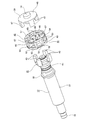
- FIG. 1 is a partially cut side view showing an example of an electric power steering device including an electric motor with a worm reducer according to an embodiment of the present invention.
- FIG. 2 is a cross-sectional view taken along the line AA of FIG.
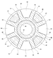
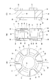
- FIG. 3 (A) is an end view showing an example torque transmission joint according to the embodiment of the present invention
- FIG. 3 (B) is a side view seen from the left side of FIG. 3 (A).
- (C) is a cross-sectional view taken along the line BB of FIG. 3 (A).
- FIG. 4 is a cross-sectional view taken along the line CC of FIG. 3 (B).
- FIG. 5 is a cross-sectional view taken along the line DD of FIG. 3 (C).
- FIG. 6 is a cross-sectional view taken along the line EE of FIG. 3 (C).
- FIG. 7 is a cross-sectional view taken along the line FF of FIG. 3 (C).
- FIG. 8 is a perspective view showing a torque transmission joint of one example of the embodiment of the present invention, in which a part thereof is disassembled and a second rotating member is supported and fixed to a worm.
- FIG. 9 is a perspective view showing an exploded view of an example torque transmission joint according to the embodiment of the present invention.
- 10 (A) is an end view showing the first rotating member
- FIG. 10 (B) is a side view seen from the left side of FIG. 10 (A)
- FIG. 10 (C) is FIG. 10 (C). It is a cross-sectional view of GG of A).
- FIG. 11 (A) is an end view showing the second rotating member
- FIG. 11 (B) is a side view seen from the right side of FIG. 11 (A)
- FIG. 11 (C) is FIG. 11 (C).
- 12 (A) is an end view showing the coupling
- FIG. 12 (B) is a side view seen from the right side of FIG. 12 (A)
- FIG. 12 (C) is FIG. 12 (A).
- FIG. 13 is an enlarged view of part J in FIG. 12 (B).
- 14 (A) is a side view of the elastic body
- FIG. 14 (B) is an end view seen from the right side of FIG. 14 (A)
- FIG. 14 (C) is a view of FIG. 14 (A). It is an end view seen from the left side.
- FIG. 15 is a diagram corresponding to FIG. 13 showing a modified example of one example of the embodiment.
- FIG. 16 is a partially cut side view showing a pinion assist type electric power steering device in which the electric motor with a worm reducer of the present invention can be incorporated.
- FIG. 17 is a partially cut side view showing a double pinion type electric power steering device in which the electric motor with a worm reducer of the present invention can be incorporated.
- Example of Embodiment] 1 to 14 (C) show an example of the embodiment of the present invention.
- This example is an example in which the electric motor with a worm reducer of the present invention is applied to a column assist type electric power steering device.
- the electric power steering device 1 the rotation of the steering wheel 2 is transmitted to the input shaft 4 of the steering gear unit 3. That is, the steering wheel 2 is supported and fixed to the rear end of the steering shaft 5, and the front end of the steering shaft 5 is connected to the rear end of the intermediate shaft 7 via the universal joint 6a. Has been done.
- the front end of the intermediate shaft 7 is connected to the input shaft 4 via another universal joint 6b.
- the rotation of the input shaft 4 is converted into a linear motion in the axial direction of the rack shaft (not shown) arranged in the width direction of the vehicle body in the steering gear unit 3.
- a steering angle is given to the steering wheels.
- the steering shaft 5 is rotatably supported inside the steering column 9 supported by the vehicle body.
- the electric power steering device 1 includes an electric motor 10 with a worm reducer.
- the electric power steering device 1 of this example is configured so that the force required for the driver to operate the steering wheel 2 can be reduced by applying the power of the electric motor 10 with a worm reducer to the steering shaft 5.
- the electric motor 10 with a worm reducer includes an electric motor 11, a worm reducer 12, and a torque transmission joint 13.
- the electric motor 11 has an output shaft 14.
- the electric motor 11 rotationally drives the output shaft 14 in both directions based on energization.
- the worm reducer 12 includes a housing 15, a worm wheel 16, and a worm 17.
- the housing 15 has a wheel accommodating portion 18 and a worm accommodating portion 19 having a central axis twisted with respect to the central axis of the wheel accommodating portion 18 and having an axial middle portion opened in the wheel accommodating portion 18. , Equipped with.
- the wheel accommodating portion 18 is supported and fixed to the front end of the steering column 9 so that its own central axis and the central axis of the steering column 9 are coaxial.
- the worm accommodating portion 19 is formed in a tubular shape and has openings at both ends in the axial direction.
- the opening on one side (right side in FIG. 2) of the worm accommodating portion 19 in the axial direction is closed by an electric motor 11 coupled and fixed to the housing 15.
- the opening on the other side (left side in FIG. 2) of the worm accommodating portion 19 in the axial direction is closed by the lid 20.
- FIG. 2 FIG. 3 (B), FIG. 3 (C), FIG. 8, FIG. 9, FIG. 10 (B), FIG. 10 (C), FIG. 11 (B), which is the base end side of the worm 17.
- FIGS. 11 (C), 12 (B) and 12 (C) Refers to the right side of FIGS. 11 (C), 12 (B) and 12 (C), and the other side in the axial direction is the tip side of the worm 17, which is the tip side of the worm 17, FIG. C), FIG. 8, FIG. 9, FIG. 10 (B), FIG. 10 (C), FIG. 11 (B), FIG. 11 (C), FIG. 12 (B) and the left side of FIG. 12 (C).
- the worm accommodating portion 19 has a cylindrical surface portion 21 having a cylindrical surface shape on the inner peripheral surface of one side portion in the axial direction, and a stepped portion facing one side in the axial direction at the other end portion in the axial direction of the cylindrical surface portion 21. Has 22. Further, the worm accommodating portion 19 has a cylindrical guide holding portion 23 on the inner peripheral surface of the other side portion in the axial direction.
- the worm wheel 16 has wheel teeth 24, which are helical gears, on the outer peripheral surface, and is rotatably supported inside the wheel accommodating portion 18.
- the worm wheel 16 is supported and fixed so as to rotate integrally with the steering shaft 5 around the front end portion of the steering shaft 5 rotatably supported inside the wheel accommodating portion 18.
- the worm wheel 16 of this example is formed by coupling and fixing an outer wheel element 26 made of synthetic resin having wheel teeth 24 on the outer peripheral surface around an inner wheel element 25 made of metal and having a circular plate shape.
- the worm 17 has screw-shaped worm teeth 27 that mesh with the wheel teeth 24 of the worm wheel 16 on the outer peripheral surface of the intermediate portion in the axial direction, and is rotatably supported inside the worm accommodating portion 19.
- the worm 17 is provided with a fitting cylinder portion 28 on one side in the axial direction with respect to the worm teeth 27.
- the fitting cylinder portion 28 is rotatably supported by the ball bearing 29 with respect to the cylindrical surface portion 21 of the worm accommodating portion 19.
- the outer ring of the ball bearing 29 is internally fitted to the cylindrical surface portion 21 in a state where displacement in the axial direction is prevented.
- the inner ring of the ball bearing 29 is fitted onto the fitting cylinder portion 28 without rattling.
- the inner ring of the ball bearing 29 has a flange portion 30 provided on a portion of the worm 17 adjacent to one side of the worm tooth 27 in the axial direction, and a torque transmission joint 13 externally fitted and fixed to the base end portion of the worm 17.
- the ball bearing 29 has a radial gap between the outer ring and the inner ring and the ball.
- the fitting cylinder portion 28 of the worm 17 is supported so as to be rotationally and oscillatingly displaced with respect to the cylindrical surface portion 21 of the worm accommodating portion 19.
- the structure of the worm 17 that supports the portion of the worm 17 located on one side in the axial direction with respect to the worm housing portion 19 so as to be able to rotate and swing is not limited to the above example. Various structures can be adopted.
- the worm 17 is provided with a small diameter tubular portion 33 at the tip portion.
- the small-diameter tubular portion 33 is supported by the support bearing 34 and the guide member 35 with respect to the guide holding portion 23 of the worm accommodating portion 19 so as to be able to rotate freely and to move in perspective with respect to the worm wheel 16.
- the inner ring of the support bearing 34 is externally fitted and fixed to the small diameter tubular portion 33.
- the outer ring of the support bearing 34 is held inside the guide member 35 so as to be able to move in perspective with respect to the worm wheel 16.
- the guide member 35 is held inside the guide holding portion 23 in a state where rotation is blocked.
- the guide member 35 locks the elastic ring 37 in the locking groove 36 provided on the outer peripheral surface over the entire circumference.
- the elastic ring 37 presses the portion of the outer peripheral surface of the guide member 35 far from the worm wheel 16 against the guide holding portion 23 to suppress rattling with respect to the guide holding portion 23.
- the support bearing 34 is elastically attached toward the worm wheel 16 side by a leaf spring 38 arranged at the end on the side far from the worm wheel 16 in the portion between the outer ring of the support bearing 34 and the guide member 35. It is being driven. As a result, backlash between the wheel teeth 24 and the worm teeth 27 is suppressed.
- the mechanism for elastically urging the tip of the worm 17 toward the worm wheel 16 side is not limited to the above example, and various structures can be adopted.
- the base end of the worm 17 is connected to the output shaft 14 of the electric motor 11 via a torque transmission joint 13 so as to be able to transmit torque.
- the torque transmission joint 13 includes a first rotating member 31, a second rotating member 39, a coupling 40, a first elastic body 41, and a second, which are coaxially arranged. It includes an elastic body 42.
- the first rotating member 31 has first convex portions 43 projecting toward one side in the axial direction at a plurality of locations in the circumferential direction on one side surface in the axial direction. Specifically, as shown in FIGS. 10A to 10C, the first rotating member 31 is directed from the cylindrical base portion 44 and the end portion of the base portion 44 on one side in the axial direction to the outside in the radial direction. From the radially outer end of the annular flange portion 45 protruding over the entire circumference and a plurality of locations (4 locations in the illustrated example) at equal intervals in the circumferential direction on one side surface in the axial direction of the flange portion 45 to one side in the axial direction. A first convex portion 43 projecting toward the surface is provided.
- the first convex portion 43 has a fan-shaped end face shape when viewed from the axial direction.
- the first rotating member 31 has a cylindrical projecting portion 46 projecting from the radially inner end of one side surface of the base 44 in the axial direction toward one side in the axial direction over the entire circumference.
- the protruding portion 46 is a portion for ensuring the fitting length of the first rotating member 31 with respect to the base end portion of the worm 17.
- the first rotating member 31 is externally fitted and fixed to the base end portion of the worm 17 so that torque can be transmitted.
- the first rotating member 31 is made of a synthetic resin, a sintered metal, or the like, which has higher rigidity (hard to be elastically deformed) than an elastic material such as an elastomer such as rubber constituting the first elastic body 41.
- the second rotating member 39 has second convex portions 47 protruding toward the other side in the axial direction at a plurality of locations in the circumferential direction on the other side surface in the axial direction.
- the second rotating member 39 has an annular plate-shaped base portion 48 and an axially other side surface of the base portion 48 at equal intervals in the circumferential direction. It is provided with a second convex portion 47 projecting from an end portion on the outer side in the radial direction at a plurality of locations (four locations in the illustrated example) toward the other side in the axial direction.
- the second convex portion 47 has a fan-shaped end face shape when viewed from the axial direction.
- the second rotating member 39 has a cylindrical projecting portion 49 projecting from the radially inner end of the axially other side surface of the base portion 48 toward the other side in the axial direction over the entire circumference.
- the protruding portion 49 is a portion for ensuring the fitting length of the second rotating member 39 with respect to the tip end portion of the output shaft 14 of the electric motor 11.
- the second rotating member 39 is externally fitted and fixed to the tip of the output shaft 14 of the electric motor 11 so that torque can be transmitted.
- the second rotating member 39 is made of a synthetic resin, a sintered metal, or the like, which has higher rigidity (hard to be elastically deformed) than an elastic material such as an elastomer such as rubber constituting the second elastic body 42.
- the second rotating member 39 may be made of the same material as the material constituting the first rotating member 31, or may be made of a different material.
- the coupling 40 has a first recess 50 and a second recess 51.
- the first concave portion 50 opens at a plurality of locations in the circumferential direction of the coupling 40 on the other side surface in the axial direction and the outer peripheral surface, and each of the first convex portions 43 of the first rotating member 31 causes a relative displacement in the circumferential direction. Engaged as possible.
- the second concave portion 51 is opened on one side surface in the axial direction and the outer peripheral surface at a plurality of locations in the circumferential direction deviating from the first concave portion 50 of the coupling 40 in the circumferential direction, and the second convex portion of the second rotating member 39.
- Each of the 47 has a second recess 51 that is engaged to allow relative displacement in the circumferential direction.
- the coupling 40 includes a cylindrical boss portion 52, a plurality of arm portions 53, and a plurality of first side plate portions 54. , A plurality of second side plate portions 55, and a plurality of second side plate portions 55.
- the shape of the boss portion 52 is not limited to a cylindrical shape, and may be a cylindrical shape.
- Each of the arm portions 53 is formed in the shape of a rectangular plate, and protrudes radially outward from a plurality of locations in the circumferential direction of the outer peripheral surface of the boss portion 52.
- the side surfaces of the arm 53 on both sides in the circumferential direction are formed of flat surfaces parallel to each other.
- Each of the first side plate portions 54 is a pair of arm portions 53 that protrude outward in the circumferential direction from a plurality of circumferential directions on the outer peripheral surface of one end of the boss portion 52 in the axial direction and are adjacent to each other in the circumferential direction. The ends on one side in the axial direction are connected to each other.
- Each of the first side plate portions 54 has a fan-shaped end face shape when viewed from the axial direction.
- Each of the second side plate portions 55 projects outward in the radial direction from a plurality of circumferential directions deviated from the first side plate portion 54 in the outer peripheral surface of the end portion on the other side in the axial direction of the boss portion 52.
- the ends of the pair of arm portions 53 adjacent to each other in the circumferential direction on the other side in the axial direction are connected to each other. That is, the first side plate portion 54 and the second side plate portion 55 are alternately arranged on the outer peripheral surface of the boss portion 52 in the circumferential direction.
- Each of the second side plate portions 55 has a fan-shaped end face shape when viewed from the axial direction.
- Each of the first recesses 50 is a pair in which the outer peripheral surface of the boss portion 52, the other side surfaces in the axial direction of the first side plate portion 54, and the end portion on one side in the axial direction are connected to each of the first side plate portions 54. It is defined by the circumferential side surfaces of the arm 53 facing each other.
- Each of the first convex portions 43 of the first rotating member 31 is engaged with each of the first concave portions 50 so as to be relatively displaced in the circumferential direction. That is, with the first convex portion 43 arranged inside the first concave portion 50, between the inner side surfaces of the first concave portion 50 on both sides in the circumferential direction and the outer surfaces of the first convex portion 43 on both sides in the circumferential direction. There is a gap in the circumferential direction between at least one of the portions. Further, there is a radial gap between the radial inner surface of the first convex portion 43 and the outer peripheral surface of the boss portion 52.
- Each of the second recesses 51 is a pair in which the outer peripheral surface of the boss portion 52, one side surface of the second side plate portion 55 in the axial direction, and the end portions of the second side plate portion 55 on the other side in the axial direction are connected to each other. It is defined by the circumferential side surfaces of the arm portions 53 facing each other.
- Each of the second convex portions 47 of the second rotating member 39 is engaged with each of the second concave portions 51 so as to be relatively displaced in the circumferential direction. That is, with the second convex portion 47 arranged inside the second concave portion 51, between the inner side surfaces of the second concave portion 51 on both sides in the circumferential direction and the outer surfaces of the second convex portion 47 on both sides in the circumferential direction. There is a gap in the circumferential direction between at least one of the portions. Further, there is a radial gap between the radial inner surface of the second convex portion 47 and the outer peripheral surface of the boss portion 52.
- each of the first convex portion 43 of the first rotating member 31 and each of the second convex portion 47 of the second rotating member 39 are alternately arranged in the circumferential direction, and the first The arm portion 53 of the coupling 40 is arranged so as to be displaced in the circumferential direction between the outer surface of the convex portion 43 in the circumferential direction and the outer surface of the second convex portion 47 in the circumferential direction.
- the first convex portion 43 and the second convex portion 47 are arranged. At least partly overlaps in the axial direction. That is, as shown in FIG. 4, in the CC cross section of FIG. 3B, the first convex portion 43 and the second convex portion 47 face each other in the circumferential direction. Therefore, even if the coupling 40 is damaged, the torque transmission function can be maintained by the first convex portion 43 and the second convex portion 47.
- the coupling 40 has a first support portion 56 for supporting the first elastic body 41 on each axially other side surface of the second side plate portion 55, and each of the first side plate portions 54.
- a second support portion 57 for supporting the second elastic body 42 is provided on one side surface in the axial direction.
- Each of the first support portions 56 has a fan-shaped end face shape when viewed from the axial direction, and protrudes from the other side surface in the axial direction of the second side plate portion 55 toward the other side in the axial direction.
- each of the first support portions 56 has a first locking groove 58 extending in the circumferential direction on the outer surface in the radial direction.
- Each of the second support portions 57 has a fan-shaped end face shape when viewed from the axial direction, and protrudes from one side surface in the axial direction of the first side plate portion 54 toward one side in the axial direction.
- each of the second support portions 57 has a second locking groove 59 extending in the circumferential direction on the outer surface in the radial direction.
- the coupling 40 has higher rigidity (difficult to elastically deform) than the materials constituting the first elastic body 41 and the second elastic body 42, and the first convex portion 43 and the second rotating member of the first rotating member 31. It is made of a material that can suppress the impact at the time of contact with the second convex portion 47 of 39.
- the coupling 40 is made of polyphenylene sulfide (PPS), polyetheretherketone (PEEK) or nylon, or a resin obtained by mixing reinforcing fibers with these, an elastomer such as rubber, or a woven cloth. It can be made of reinforced belt material or the like.
- the first elastic body 41 has a plurality of first elastic pieces 60 sandwiched in the circumferential direction between each of the first convex portions 43 of the first rotating member 31 and the coupling 40.
- the first elastic body 41 includes a plurality of (eight in the illustrated example) first elastic pieces 60 and the circumferential direction.
- the first inner diameter side connection piece 61 and the first outer diameter side connection piece 62 which are alternately arranged one by one (four in the illustrated example), and the first combination of a plurality (four in the illustrated example).
- a stop piece 63 and a stop piece 63 are provided.
- Each of the first elastic pieces 60 is formed in a rectangular columnar shape and is arranged in the radial direction.
- Each of the first inner diameter side connecting pieces 61 connects the radially inner ends of a pair of first elastic pieces 60 adjacent to each other in the circumferential direction.
- Each of the first inner diameter side connecting pieces 61 has an arc-shaped end face shape when viewed from the axial direction.
- Each of the first outer diameter side connection pieces 62 is arranged at a position deviated from the first inner diameter side connection piece 61 in the circumferential direction, and is radially outside of a pair of first elastic pieces 60 adjacent to each other in the circumferential direction. The ends of the are connected to each other.
- Each of the first outer diameter side connecting pieces 62 has an arc-shaped end face shape when viewed from the axial direction.
- Each of the first locking pieces 63 is arranged at a position where the first inner diameter side connection piece 61 and the phase of the first inner diameter side connection piece 61 coincide with each other in the circumferential direction, in other words, at a position deviated from the first outer diameter side connection piece 62 in the circumferential direction.
- the radial outer ends of the pair of first elastic pieces 60 adjacent to each other in the circumferential direction are connected to each other.
- Each of the first locking pieces 63 has an arcuate end face shape when viewed from the axial direction. That is, the first outer diameter side connecting piece 62 and the first locking piece 63 are alternately arranged in the circumferential direction so as to form an annular shape as a whole.
- the axial thickness of the first locking piece 63 is made smaller than the axial thickness of the first elastic piece 60, the first inner diameter side connection piece 61, and the first outer diameter side connection piece 62.
- the axial thickness of the first locking piece 63 is set to about half the axial thickness of the first elastic piece 60, the first inner diameter side connection piece 61, and the first outer diameter side connection piece 62.
- the axial thicknesses of the first elastic piece 60, the first inner diameter side connection piece 61, and the first outer diameter side connection piece 62 are all the same. That is, the other side surface in the axial direction of the first locking piece 63 of the first elastic body 41 is located on one side in the axial direction with respect to the other side surface in the axial direction of the remaining portion.
- the circumferential dimension of the portion between the pair of first elastic pieces 60 in which the radial outer end is connected to the first outer diameter side connecting piece 62 is the circumference of the first recess 50 of the coupling 40. Smaller than the directional dimension.
- the first elastic body 41 is a substantially trapezoidal annular first supported body composed of a pair of first elastic pieces 60 adjacent to each other in the circumferential direction, a first inner diameter side connecting piece 61, and a first locking piece 63. It has a part 73. Then, by engaging (outer fitting) each of the first supported portions 73 with each of the first supporting portions 56, the first elastic body 41 is supported by the end portion of the coupling 40 on the other side in the axial direction. ing. Specifically, the first locking piece 63 is locked in the first locking groove 58, and the first support portion 56 is elastically sandwiched from both sides in the circumferential direction by the pair of first elastic pieces 60. By elastically contacting the radial outer surface of the first inner diameter side connection piece 61 with the radial inner surface of the first support portion 56, the first elastic body 41 is brought into contact with the axially other end of the coupling 40. I support the club.
- the first convex portion of the first rotating member 31 is located between the pair of first elastic pieces 60, which are connected to the first outer diameter side connecting piece 62 at the outer end in the radial direction. 43 is inserted. That is, each of the first elastic pieces 60 has a circumferential side surface of the first convex portion 43 of the first rotating member 31 and a circumferential side surface of the first support portion 56 of the coupling 40. It is sandwiched between.
- the radial outer surface of the first convex portion 43 may be in contact with the radial inner surface of the first outer diameter side connection piece 62, or may be non-contact.
- the first elastic body 41 has a plurality of (four in the illustrated example) first protrusions 64 protruding toward the other side in the axial direction on the other side surface in the axial direction.
- the first elastic body 41 has a first protrusion 64 at the center position in the circumferential direction of each axially other side surface of the first inner diameter side connecting piece 61.
- each of the first protrusions 64 Elastically contacts one side surface of the flange portion 45 of the first rotating member 31 in the axial direction.
- the second elastic body 42 has a plurality of second elastic pieces 65 sandwiched in the circumferential direction between each of the second convex portions 47 of the second rotating member 39 and the coupling 40.
- the second elastic body 42 the one having the same specifications as the first elastic body 41 (the one having the same shape, dimensions, and material) is used. That is, as shown in FIGS. 14 (A) to 14 (C), the second elastic bodies 42 are alternately plural with a plurality of (8 in the illustrated example) second elastic pieces 65 in the circumferential direction.
- the second elastic body 42 is a substantially trapezoidal annular second supported body composed of a pair of second elastic pieces 65 adjacent to each other in the circumferential direction, a second inner diameter side connecting piece 66, and a second locking piece 68. It has a part 74. Then, by engaging (outer fitting) each of the second supported portions 74 with each of the second supporting portions 57, the second elastic body 42 is supported by one end of the coupling 40 in the axial direction. There is. Specifically, the second locking piece 68 is locked in the second locking groove 59, and the second support portion 57 is elastically sandwiched from both sides in the circumferential direction by the pair of second elastic pieces 65. By elastically contacting the radial outer surface of the second inner diameter side connection piece 66 with the radial inner surface of the second support portion 57, the second elastic body 42 is brought into contact with the axial one-side end of the coupling 40. Supports.
- the second convex portion of the second rotating member 39 is located between the pair of second elastic pieces 65, which are connected to the second outer diameter side connecting piece 67 at the outer end in the radial direction. 47 is inserted. That is, each of the second elastic pieces 65 is between the respective circumferential side surfaces of the second convex portion 47 of the second rotating member 39 and the respective circumferential side surfaces of the second support portion 57 of the coupling 40. It is sandwiched between.
- the radial outer surface of the second convex portion 47 may be in contact with the radial inner surface of the second outer diameter side connection piece 67, or may be non-contact.
- the second elastic body 42 has a plurality of (four in the illustrated example) second protrusions 69 protruding toward one side in the axial direction on one side surface in the axial direction.
- the second elastic body 42 has a second protrusion 69 at the center position in the circumferential direction of each side surface of the second inner diameter side connecting piece 66 in the axial direction.
- each of the second protrusions 69 Elastically contacts the other side surface of the base 48 of the second rotating member 39 in the axial direction.
- the second rotation is accompanied by the rotation of the output shaft 14.
- the outer surface of the second convex portion 47 of the member 39 in the circumferential direction passes through the second elastic piece 65 of the second elastic body 42, and the outer surface of the second support portion 57 of the coupling 40 is in the circumferential direction. Press on.
- the outer surface of the first support portion 56 of the coupling 40 in the circumferential direction passes through the first elastic piece 60 of the first elastic body 41, and the first rotating member 31 first.
- the outer surface of the convex portion 43 in the circumferential direction is pressed. In this way, the rotational torque of the output shaft 14 is transmitted to the worm 17.
- the second elastic piece 65 of the second elastic body 42 goes out of the circumferential direction of the second support portion 57 of the coupling 40.
- the first elastic piece 60 of the first elastic body 41 is elastically crushed in the circumferential direction between the side surface and the outer surface of the second convex portion 47 of the second rotating member 39 in the circumferential direction. It is elastically crushed in the circumferential direction between the outer surface of the first support portion 56 of the coupling 40 in the circumferential direction and the outer surface of the first convex portion 43 of the first rotating member 31 in the circumferential direction.
- the outer surface of the second convex portion 47 of the second rotating member 39 in the circumferential direction and the inner surface of the second concave portion 51 of the coupling 40 in the circumferential direction are in direct contact with each other, and the first The outer surface of the first convex portion 43 of the rotating member 31 in the circumferential direction and the inner surface of the first concave portion 50 of the coupling 40 in the circumferential direction directly abut each other. Since the momentum of these abuttals is weakened by the first elastic body 41 and the second elastic body 42, the outer surface of the second convex portion 47 in the circumferential direction and the circle of the second concave portion 51 accompany the abutting.
- Abnormal noise such as jarring rattling noise is heard at the contact portion with the inner surface in the circumferential direction and the contact portion between the outer surface in the circumferential direction of the first convex portion 43 and the inner surface in the circumferential direction of the first concave portion 50. It can be prevented from occurring. Further, in this state, most of the rotational torque of the output shaft 14 is transmitted to the coupling 40 from the contact portion between the outer surface of the second convex portion 47 in the circumferential direction and the inner surface of the second concave portion 51 in the circumferential direction. Most of the torque transmitted to the coupling 40 is transmitted to the worm 17 from the contact portion between the outer surface of the first convex portion 43 in the circumferential direction and the inner surface of the first concave portion 50 in the circumferential direction. Will be done.
- the cups do not match.
- the output shaft 14 and the worm 17 are tilted by the ring 40 with respect to the central axis of the worm 17 and / or the central axis of the output shaft 14 while elastically deforming the first elastic body 41 and / or the second elastic body 42.
- the torque can be smoothly transmitted to and from the vehicle.
- the first elastic body 41 has a first protrusion 64 at the center position in the circumferential direction of each axial and other side surface of the first inner diameter side connecting piece 61.
- first protrusion 64 When the central axis of the coupling 40 coincides with the central axis of the worm 17 and / or the central axis of the output shaft 14 (when the coupling 40 is not tilted with respect to the axial direction), each of the first protrusions 64 Does not come into contact with one side surface of the flange portion 45 of the first rotating member 31 in the axial direction.
- each of the first protrusions 64 Elastically contacts one side surface of the flange portion 45 of the first rotating member 31 in the axial direction. Therefore, when the coupling 40 is tilted with respect to the central axis of the worm 17 and / or the central axis of the output shaft 14, one side surface of the flange portion 45 of the first rotating member 31 collides with the first protrusion 64.
- the speed can be reduced (slowened) as compared with the case where the first protrusion 64 is arranged in the radial outer portion. Therefore, it is possible to suppress the abnormal noise caused by the one side surface of the flange portion 45 of the first rotating member 31 colliding with the first protrusion 64 in the axial direction.
- the second elastic body 42 has a second protrusion 69 at the center position in the circumferential direction of each axially other side surface of the second inner diameter side connecting piece 66.
- each of the second protrusions 69 is a second rotating member. Elastically contacts the other side surface of the base 48 of 39 in the axial direction. Therefore, when the coupling 40 is tilted with respect to the central axis of the worm 17 and / or the central axis of the output shaft 14, the speed at which the other side surface of the base 48 of the second rotating member 39 collides with the second protrusion 69. Can be made smaller (slower). Therefore, it is possible to suppress the abnormal noise caused by the axial other side surface of the base portion 48 of the second rotating member 39 colliding with the second protrusion 69.
- the rigidity of the first elastic body and the second elastic body may be different from each other, or the circumferential gap between the first convex portion and the first concave portion and the second convex portion may be used. It is also possible to make the circumferential gap between the second recess and the second recess different from each other.
- the magnitude of the transmission torque that collides with the inner surface in the circumferential direction can be made different.
- the torque transmission characteristics between the output shaft of the electric motor and the worm can be divided into multiple stages, and the operation feeling of the steering wheel can be improved.
- each of the first recesses 50a has a circumferential width dimension between the axial other side portions of the inner side surfaces facing each other in the circumferential direction from the circumferential width dimension between the axial one side portions.
- Each of the second recesses 51a has a circumferential width dimension between the axial one side portions of the inner side surfaces facing each other in the circumferential direction, and a circumferential width dimension between the axial other side portions. Is larger than.
- the inner surfaces on both sides of the first concave portion 50a in the circumferential direction are opposed to each other.
- a step portion 72a is formed which is inclined in a direction away from each other toward the other side in the axial direction.
- the inner side surfaces of the second concave portion 51a on both sides in the circumferential direction (the circumferential side surfaces of the pair of arm portions 53a facing each other, in which the end portions on the other side in the axial direction are connected to each of the second side plate portions 55).
- a step portion 72b is formed in a portion of the intermediate portion in the axial direction located on one side in the axial direction with respect to the step portion 72a, which is inclined in a direction away from each other toward one side in the axial direction.
- the circumferential width dimension of each of the inner side surfaces of the second recess 51 in the axial direction is made larger than the circumferential width dimension of the other side portions in the axial direction.
- one side portion in the axial direction (the portion surrounded by the chain line ⁇ in FIG. 15) of the inner side surface in the circumferential direction of the first recess 50a is the first.
- One convex portion 43 is in contact with the outer surface in the circumferential direction
- the other side portion in the axial direction (the portion surrounded by the chain line ⁇ in FIG. 15) of the inner side surface in the circumferential direction of the second concave portion 51a is the second convex portion. It comes into contact with the outer surface of the portion 47 in the circumferential direction.
- the circle of the first convex portion 43 is formed.
- the contact position of the inner side surface of the first concave portion 50a with respect to the outer surface in the circumferential direction can be set to be near the central position in the axial direction of the coupling 40a, and the contact position with respect to the outer surface of the second convex portion 47 in the circumferential direction.
- the contact position of the inner surface of the second recess 51a in the circumferential direction can be set to be near the central position in the axial direction of the coupling 40a.
- the coupling 40a when the coupling 40a is tilted with respect to the central axis of the worm 17 and / or the central axis of the output shaft 14, the coupling 40a can be tilted about the vicinity of the central position in the axial direction. From this aspect as well, torque can be stably transmitted between the output shaft 14 and the worm 17 via the torque transmission joint 13.
- the circumferential width dimension of the other side portions in the axial direction of the inner side surfaces of the first concave portions facing each other in the circumferential direction is made constant over the axial direction, and the shaft. While making it larger than the circumferential width dimension of each of the directional one-sided portions, the circumferential width dimension of each of the axially one-sided portions of the inner side surfaces of the second recesses facing each other in the circumferential direction is constant over the axial direction. It is also possible to make it larger than the circumferential width dimension between the other side portions in the axial direction.
- the electric motor with a worm reducer of the present invention can be incorporated not only in a column assist type electric power steering device but also in an electric power steering device having various structures.
- the electric motor with a worm reducer of the present invention when incorporated into the pinion-assisted electric power steering device 1a as shown in FIG. 16, the worm is attached to the input shaft 4a of the steering gear unit 3a.
- the worm wheel 16 of the speed reducer 12 is supported and fixed.
- the electric motor with a worm reducer of the present invention When the electric motor with a worm reducer of the present invention is incorporated into the double pinion type electric power steering device 1b as shown in FIG. 17, it is located at a portion deviated from the input shaft 4 of the steering gear unit 3 in the width direction of the vehicle. , The rotating shaft 70 to which the worm wheel 16 is fitted and fixed is arranged, and the pinion teeth provided at the tip of the rotating shaft 70 are engaged with the teeth of the rack 71 constituting the steering gear unit 3.
- the electric motor with a worm reducer of the present invention can be incorporated not only in an electric power steering device but also in various mechanical devices.
- the torque transmission joint of the present invention is not limited to the electric motor with a worm reducer, and can be used by being incorporated between a pair of rotating shafts arranged coaxially with each other in the torque transmission path of various mechanical devices. it can.
Landscapes
- Engineering & Computer Science (AREA)
- Mechanical Engineering (AREA)
- Chemical & Material Sciences (AREA)
- Combustion & Propulsion (AREA)
- Transportation (AREA)
- General Engineering & Computer Science (AREA)
- Power Steering Mechanism (AREA)
- Gear Transmission (AREA)
- Connection Of Motors, Electrical Generators, Mechanical Devices, And The Like (AREA)
Priority Applications (4)
| Application Number | Priority Date | Filing Date | Title |
|---|---|---|---|
| US17/782,377 US12391305B2 (en) | 2019-12-04 | 2020-12-02 | Torque transfer joint and electric motor with worm reduction gear |
| EP20895822.3A EP4071980B1 (en) | 2019-12-04 | 2020-12-02 | Torque transfer joint and electric motor with worm reduction gear |
| JP2021562700A JP7287496B2 (ja) | 2019-12-04 | 2020-12-02 | トルク伝達継手およびウォーム減速機付電動モータ |
| CN202080084143.9A CN114787526B (zh) | 2019-12-04 | 2020-12-02 | 扭矩传递接头以及带蜗杆减速器的电动马达 |
Applications Claiming Priority (2)
| Application Number | Priority Date | Filing Date | Title |
|---|---|---|---|
| JP2019-219337 | 2019-12-04 | ||
| JP2019219337 | 2019-12-04 |
Publications (1)
| Publication Number | Publication Date |
|---|---|
| WO2021112153A1 true WO2021112153A1 (ja) | 2021-06-10 |
Family
ID=76221115
Family Applications (1)
| Application Number | Title | Priority Date | Filing Date |
|---|---|---|---|
| PCT/JP2020/044945 Ceased WO2021112153A1 (ja) | 2019-12-04 | 2020-12-02 | トルク伝達継手およびウォーム減速機付電動モータ |
Country Status (5)
| Country | Link |
|---|---|
| US (1) | US12391305B2 (https=) |
| EP (1) | EP4071980B1 (https=) |
| JP (1) | JP7287496B2 (https=) |
| CN (1) | CN114787526B (https=) |
| WO (1) | WO2021112153A1 (https=) |
Cited By (1)
| Publication number | Priority date | Publication date | Assignee | Title |
|---|---|---|---|---|
| WO2024122164A1 (ja) * | 2022-12-07 | 2024-06-13 | Nskステアリング&コントロール株式会社 | トルク伝達継手およびその組立方法、ならびにウォーム減速機付電動モータ |
Families Citing this family (1)
| Publication number | Priority date | Publication date | Assignee | Title |
|---|---|---|---|---|
| CN115892204B (zh) * | 2022-12-31 | 2026-04-28 | 芜湖世特瑞转向系统有限公司 | 一种联接盘 |
Citations (8)
| Publication number | Priority date | Publication date | Assignee | Title |
|---|---|---|---|---|
| JP2004306898A (ja) | 2003-04-10 | 2004-11-04 | Nsk Ltd | 電動式パワーステアリング装置用アシスト装置及び電動式パワーステアリング装置 |
| JP2013228061A (ja) * | 2012-04-26 | 2013-11-07 | Nsk Ltd | トルク伝達用継手及び電動式パワーステアリング装置 |
| JP2015081669A (ja) * | 2013-10-24 | 2015-04-27 | 日本精工株式会社 | トルク伝達用継手及び電動式パワーステアリング装置 |
| JP2015169225A (ja) * | 2014-03-05 | 2015-09-28 | アスモ株式会社 | ジョイント装置及びモータ |
| JP2015217704A (ja) * | 2014-05-14 | 2015-12-07 | 株式会社ジェイテクト | 電動パワーステアリング装置 |
| WO2018216233A1 (ja) * | 2017-05-26 | 2018-11-29 | 株式会社ショーワ | 電動パワーステアリング装置、軸継手 |
| WO2019049389A1 (ja) * | 2017-09-11 | 2019-03-14 | 株式会社ショーワ | 電動パワーステアリング装置、軸継手 |
| JP2019219337A (ja) | 2018-06-22 | 2019-12-26 | アイシン精機株式会社 | 超音波センサ装置 |
Family Cites Families (11)
| Publication number | Priority date | Publication date | Assignee | Title |
|---|---|---|---|---|
| DE2706034A1 (de) * | 1977-02-12 | 1978-08-17 | Herwarth Reich Nachf Dipl Ing | Elastische klauenkupplung |
| US6183368B1 (en) * | 1997-10-09 | 2001-02-06 | Ntn Corporation | One-way over-running flex coupling |
| JP5048804B2 (ja) * | 2010-03-31 | 2012-10-17 | 日立オートモティブシステムズ株式会社 | パワーステアリング装置 |
| JP2013249846A (ja) * | 2010-08-23 | 2013-12-12 | Honda Motor Co Ltd | ウォームギヤ機構及びウォームギヤ機構を搭載した電動パワーステアリング装置 |
| JP5708981B2 (ja) * | 2010-09-09 | 2015-04-30 | 株式会社ジェイテクト | 電動パワーステアリング装置 |
| KR101413458B1 (ko) * | 2010-12-28 | 2014-07-01 | 가부시키가이샤규슈하세쿠 | 기어 커플링 및 그 제조 방법 |
| JP5798946B2 (ja) * | 2012-02-24 | 2015-10-21 | カヤバ工業株式会社 | 電動パワーステアリング装置、及びそれに用いられる軸連結器 |
| JP5923656B2 (ja) * | 2013-02-22 | 2016-05-24 | 鍋屋バイテック株式会社 | カップリング |
| KR101686206B1 (ko) * | 2013-04-02 | 2016-12-13 | 주식회사 만도 | 자동차의 전동식 동력 보조 조향장치 및 이의 조립 방법 |
| JP6332467B2 (ja) * | 2014-09-26 | 2018-05-30 | 日本精工株式会社 | トルク伝達用継手及び電動式パワーステアリング装置 |
| CN109790873B (zh) * | 2016-10-13 | 2021-08-31 | 日本精工株式会社 | 力矩传递用接头和电动式助力转向装置 |
-
2020
- 2020-12-02 CN CN202080084143.9A patent/CN114787526B/zh active Active
- 2020-12-02 EP EP20895822.3A patent/EP4071980B1/en active Active
- 2020-12-02 WO PCT/JP2020/044945 patent/WO2021112153A1/ja not_active Ceased
- 2020-12-02 JP JP2021562700A patent/JP7287496B2/ja active Active
- 2020-12-02 US US17/782,377 patent/US12391305B2/en active Active
Patent Citations (8)
| Publication number | Priority date | Publication date | Assignee | Title |
|---|---|---|---|---|
| JP2004306898A (ja) | 2003-04-10 | 2004-11-04 | Nsk Ltd | 電動式パワーステアリング装置用アシスト装置及び電動式パワーステアリング装置 |
| JP2013228061A (ja) * | 2012-04-26 | 2013-11-07 | Nsk Ltd | トルク伝達用継手及び電動式パワーステアリング装置 |
| JP2015081669A (ja) * | 2013-10-24 | 2015-04-27 | 日本精工株式会社 | トルク伝達用継手及び電動式パワーステアリング装置 |
| JP2015169225A (ja) * | 2014-03-05 | 2015-09-28 | アスモ株式会社 | ジョイント装置及びモータ |
| JP2015217704A (ja) * | 2014-05-14 | 2015-12-07 | 株式会社ジェイテクト | 電動パワーステアリング装置 |
| WO2018216233A1 (ja) * | 2017-05-26 | 2018-11-29 | 株式会社ショーワ | 電動パワーステアリング装置、軸継手 |
| WO2019049389A1 (ja) * | 2017-09-11 | 2019-03-14 | 株式会社ショーワ | 電動パワーステアリング装置、軸継手 |
| JP2019219337A (ja) | 2018-06-22 | 2019-12-26 | アイシン精機株式会社 | 超音波センサ装置 |
Cited By (1)
| Publication number | Priority date | Publication date | Assignee | Title |
|---|---|---|---|---|
| WO2024122164A1 (ja) * | 2022-12-07 | 2024-06-13 | Nskステアリング&コントロール株式会社 | トルク伝達継手およびその組立方法、ならびにウォーム減速機付電動モータ |
Also Published As
| Publication number | Publication date |
|---|---|
| US12391305B2 (en) | 2025-08-19 |
| JPWO2021112153A1 (https=) | 2021-06-10 |
| EP4071980A4 (en) | 2023-01-18 |
| CN114787526A (zh) | 2022-07-22 |
| US20230024110A1 (en) | 2023-01-26 |
| CN114787526B (zh) | 2024-09-24 |
| EP4071980B1 (en) | 2024-06-12 |
| EP4071980A1 (en) | 2022-10-12 |
| JP7287496B2 (ja) | 2023-06-06 |
Similar Documents
| Publication | Publication Date | Title |
|---|---|---|
| US7575090B2 (en) | Electric power steering device | |
| JP6439897B2 (ja) | トルク伝達用継手及び電動式パワーステアリング装置 | |
| JP6332467B2 (ja) | トルク伝達用継手及び電動式パワーステアリング装置 | |
| US6761244B2 (en) | Electric power steering apparatus | |
| CN109563885B (zh) | 扭矩传递用联轴器和电动式助力转向装置 | |
| JP6277895B2 (ja) | トルク伝達部材及び駆動軸と被駆動軸との結合部 | |
| JP7404688B2 (ja) | ウォーム減速機および電動アシスト装置 | |
| JP5217676B2 (ja) | ウォーム減速機付回転駆動装置 | |
| WO2021112153A1 (ja) | トルク伝達継手およびウォーム減速機付電動モータ | |
| EP1777140A1 (en) | Tensioner for belt-type transmission and electric power steering apparatus having the same | |
| JP7225877B2 (ja) | ウォーム減速機および電動アシスト装置 | |
| EP3926190A1 (en) | Worm reducer and electric assist device | |
| JP5157666B2 (ja) | 弾性軸継手及び電動式パワーステアリング装置 | |
| JP5181747B2 (ja) | 電動式パワーステアリング装置 | |
| WO2021241135A1 (ja) | ウォーム減速機および電動アシスト装置 | |
| CN107002821B (zh) | 蜗杆减速器和电动助力装置 | |
| WO2019022015A1 (ja) | トルク伝達用継手および電動式パワーステアリング装置 | |
| EP4632245A1 (en) | Torque transmission joint, method for assembling same, and electric motor with worm reduction gear | |
| JPWO2024122164A5 (https=) | ||
| JP7255333B2 (ja) | ウォーム減速機及び電動アシスト装置 | |
| JP4313683B2 (ja) | ギヤドモータ | |
| CN119630903A (zh) | 蜗杆减速器 | |
| JPH05180236A (ja) | 軸継手 | |
| JP2000027878A (ja) | 軸継手 | |
| JP2007247707A (ja) | 軸継手 |
Legal Events
| Date | Code | Title | Description |
|---|---|---|---|
| 121 | Ep: the epo has been informed by wipo that ep was designated in this application |
Ref document number: 20895822 Country of ref document: EP Kind code of ref document: A1 |
|
| ENP | Entry into the national phase |
Ref document number: 2021562700 Country of ref document: JP Kind code of ref document: A |
|
| NENP | Non-entry into the national phase |
Ref country code: DE |
|
| ENP | Entry into the national phase |
Ref document number: 2020895822 Country of ref document: EP Effective date: 20220704 |
|
| WWG | Wipo information: grant in national office |
Ref document number: 17782377 Country of ref document: US |