WO2021112153A1 - Torque transfer joint and electric motor with worm reduction gear - Google Patents
Torque transfer joint and electric motor with worm reduction gear Download PDFInfo
- Publication number
- WO2021112153A1 WO2021112153A1 PCT/JP2020/044945 JP2020044945W WO2021112153A1 WO 2021112153 A1 WO2021112153 A1 WO 2021112153A1 JP 2020044945 W JP2020044945 W JP 2020044945W WO 2021112153 A1 WO2021112153 A1 WO 2021112153A1
- Authority
- WO
- WIPO (PCT)
- Prior art keywords
- circumferential direction
- axial direction
- worm
- circumferential
- coupling
- Prior art date
Links
Images


Classifications
-
- B—PERFORMING OPERATIONS; TRANSPORTING
- B62—LAND VEHICLES FOR TRAVELLING OTHERWISE THAN ON RAILS
- B62D—MOTOR VEHICLES; TRAILERS
- B62D5/00—Power-assisted or power-driven steering
- B62D5/04—Power-assisted or power-driven steering electrical, e.g. using an electric servo-motor connected to, or forming part of, the steering gear
- B62D5/0442—Conversion of rotational into longitudinal movement
- B62D5/0454—Worm gears
-
- F—MECHANICAL ENGINEERING; LIGHTING; HEATING; WEAPONS; BLASTING
- F16—ENGINEERING ELEMENTS AND UNITS; GENERAL MEASURES FOR PRODUCING AND MAINTAINING EFFECTIVE FUNCTIONING OF MACHINES OR INSTALLATIONS; THERMAL INSULATION IN GENERAL
- F16D—COUPLINGS FOR TRANSMITTING ROTATION; CLUTCHES; BRAKES
- F16D3/00—Yielding couplings, i.e. with means permitting movement between the connected parts during the drive
- F16D3/50—Yielding couplings, i.e. with means permitting movement between the connected parts during the drive with the coupling parts connected by one or more intermediate members
- F16D3/64—Yielding couplings, i.e. with means permitting movement between the connected parts during the drive with the coupling parts connected by one or more intermediate members comprising elastic elements arranged between substantially-radial walls of both coupling parts
- F16D3/68—Yielding couplings, i.e. with means permitting movement between the connected parts during the drive with the coupling parts connected by one or more intermediate members comprising elastic elements arranged between substantially-radial walls of both coupling parts the elements being made of rubber or similar material
-
- B—PERFORMING OPERATIONS; TRANSPORTING
- B62—LAND VEHICLES FOR TRAVELLING OTHERWISE THAN ON RAILS
- B62D—MOTOR VEHICLES; TRAILERS
- B62D5/00—Power-assisted or power-driven steering
- B62D5/04—Power-assisted or power-driven steering electrical, e.g. using an electric servo-motor connected to, or forming part of, the steering gear
- B62D5/0409—Electric motor acting on the steering column
-
- B—PERFORMING OPERATIONS; TRANSPORTING
- B62—LAND VEHICLES FOR TRAVELLING OTHERWISE THAN ON RAILS
- B62D—MOTOR VEHICLES; TRAILERS
- B62D7/00—Steering linkage; Stub axles or their mountings
- B62D7/16—Arrangement of linkage connections
-
- F—MECHANICAL ENGINEERING; LIGHTING; HEATING; WEAPONS; BLASTING
- F16—ENGINEERING ELEMENTS AND UNITS; GENERAL MEASURES FOR PRODUCING AND MAINTAINING EFFECTIVE FUNCTIONING OF MACHINES OR INSTALLATIONS; THERMAL INSULATION IN GENERAL
- F16D—COUPLINGS FOR TRANSMITTING ROTATION; CLUTCHES; BRAKES
- F16D3/00—Yielding couplings, i.e. with means permitting movement between the connected parts during the drive
- F16D3/02—Yielding couplings, i.e. with means permitting movement between the connected parts during the drive adapted to specific functions
- F16D3/12—Yielding couplings, i.e. with means permitting movement between the connected parts during the drive adapted to specific functions specially adapted for accumulation of energy to absorb shocks or vibration
Definitions
- the present invention relates to a torque transmission joint incorporated in various mechanical devices and used to transmit torque between a pair of rotating members, and an electric motor with a worm reducer provided with the torque transmission joint.
- the power steering device is widely used because it can reduce the force required for the driver to operate the steering wheel.
- the electric power steering device has advantages such as being smaller and lighter than the hydraulic power steering device, being able to easily control the size of the auxiliary power, and having less power loss of the engine, and is used frequently. Is increasing.
- auxiliary power of the electric motor is applied to the steering rotating shaft that rotates based on the operation of the steering wheel via the reduction gear.
- a speed reducer a worm speed reducer is widely used because a large reduction ratio can be obtained.
- Patent Document 1 Japanese Patent Application Laid-Open No. 2004-306898 (Patent Document 1), among a pair of bearings for rotatably supporting a worm with respect to a housing, between the bearing arranged on the tip side of the worm and the housing.
- Patent Document 1 Discloses a structure in which an urging member including a spring is arranged and the tip of the worm is urged toward the worm wheel. According to such a structure, the backlash of the meshing portion can be suppressed, and the generation of rattling noise at the meshing portion between the worm wheel and the worm can be suppressed.
- the present invention can smoothly transmit torque between the pair of rotating members even if the central axes of the pair of rotating members do not match each other. It is an object of the present invention to realize a structure of a torque transmission joint capable of preventing the generation of abnormal noise between the pair of rotating members.
- the torque transmission joint of the present invention A first rotating member having first convex portions protruding toward one side in the axial direction at a plurality of locations in the circumferential direction on one side surface in the axial direction.
- a second rotating member having second convex portions protruding toward the other side in the axial direction at a plurality of locations in the circumferential direction on the other side surface in the axial direction.
- the first concave portion is opened at a plurality of locations in the circumferential direction at least on the other side surface in the axial direction, and each of the first convex portions is engaged with a relative displacement in the circumferential direction.
- Each of the second convex portions has a second concave portion that is open at least on one side surface in the axial direction and is engaged with each other so as to enable relative displacement in the circumferential direction at a plurality of locations in the circumferential direction deviating from the circumferential direction.
- the coupling is Cylindrical or cylindrical boss and A plurality of arms protruding outward in the radial direction from a plurality of circumferential directions on the outer peripheral surface of the boss portion. A pair of axially one-sided ends of the pair of arms projecting outward in the radial direction from a plurality of circumferential directions on the outer peripheral surface of one end of the boss portion in the axial direction.
- each of the first recesses is connected to the outer peripheral surface of the boss portion, the other side surfaces of the first side plate portion in the axial direction, and the end portion on one side in the axial direction to each of the first side plate portions.
- the pair of arm portions facing each other in the circumferential direction, and each of the second recesses is an outer peripheral surface of the boss portion and one axial side surface of the second side plate portion. And the peripheral side surfaces of the pair of the arm portions facing each other, in which the ends on the other side in the axial direction are connected to each of the second side plate portions.
- the coupling has a first support portion for supporting the first elastic body on each axial other side surface of the second side plate portion, and each axial piece of the first side plate portion.
- a second support portion for supporting the second elastic body can be provided on the side surface.
- the first elastic body may further include a first inner diameter side connecting piece, a first outer diameter side connecting piece, and a first locking piece, which are alternately arranged in a plurality in the circumferential direction.
- the first inner diameter side connecting piece connects the radially inner ends of the pair of the first elastic pieces adjacent to each other in the circumferential direction
- the first outer diameter side connecting piece is in the circumferential direction.
- a pair of adjacent first elastic pieces are connected to each other on the radial outer ends
- the first locking piece is a pair in which the radial inner ends are connected by the first inner diameter side connecting piece.
- the connecting portions on the outer side in the radial direction of the first elastic piece are connected to each other.
- the first elastic body has a first supported portion composed of a pair of the first elastic pieces adjacent to each other in the circumferential direction, the first inner diameter side connecting piece, and the first locking piece. By externally fitting to the support portion, it is supported by the coupling.
- the second elastic body may further include a second inner diameter side connecting piece, a second outer diameter side connecting piece, and a second locking piece, which are alternately arranged in a plurality in the circumferential direction.
- the second inner diameter side connecting piece connects the radially inner ends of the pair of second elastic pieces adjacent to each other in the circumferential direction, and the second outer diameter side connecting piece is in the circumferential direction.
- the second elastic body has a second supported portion composed of a pair of the second elastic pieces adjacent to each other in the circumferential direction, the second inner diameter side connecting piece, and the second locking piece. By externally fitting to the support portion, it is supported by the coupling.
- the coupling has a first locking groove extending in the circumferential direction for locking the first locking piece on the radial outer surface of the first support portion, and the second locking groove.
- a second locking groove for locking the second locking piece, which extends in the circumferential direction, can be provided on the radial outer surface of the support portion.
- the circumferential width dimension between the axially other side portions of the inner side surfaces facing each other in the circumferential direction is made larger than the circumferential width dimension between the axial one side portions, and the first recess is described.
- the second concave portion can have a circumferential width dimension between the axial one-sided portions of the inner side surfaces facing each other in the circumferential direction larger than the circumferential width dimension between the axial other side portions.
- the first elastic piece is elastically crushed in the circumferential direction, the inner surface of the first concave portion in the circumferential direction and the outer surface of the first convex portion in the circumferential direction are in contact with each other, and the second elastic piece is elastic.
- the circumference of the first recess is in a state where the piece is elastically crushed in the circumferential direction and the inner surface of the second concave portion in the circumferential direction and the outer surface of the second convex portion in the circumferential direction are in contact with each other.
- the other side portion in the axial direction of the portion that comes into contact with the outer surface in the circumferential direction of the first convex portion, and the circumference of the second convex portion among the inner side surfaces in the circumferential direction of the second concave portion It is preferable that one side portion in the axial direction of the portion that abuts on the outer surface in the direction overlaps in the circumferential direction.
- the first elastic body has a plurality of first protrusions protruding toward the other side in the axial direction on the other side surface in the axial direction
- the second elastic body has an axial direction on one side surface in the axial direction. It can have a plurality of second protrusions that project toward one side.
- the plurality of first protrusions do not contact one side surface in the axial direction of the first rotating member, and the plurality of second protrusions are said to be the second. Does not come into contact with other side surfaces of the rotating member in the axial direction.
- the plurality of first protrusions are in contact with one side surface in the axial direction of the first rotating member, and the plurality of second protrusions are the second rotating member. In contact with the other side surface in the axial direction of.
- first elastic body and the second elastic body have the same shape and dimensions and are made of the same material.
- the electric motor with a worm reducer of the present invention A worm wheel with wheel teeth on the outer peripheral surface, A worm having worm teeth that mesh with the wheel teeth on the outer peripheral surface, An electric motor with an output shaft and A torque transmission joint is provided which connects the output shaft and the worm so as to be able to transmit torque.
- the torque transmission joint is composed of the torque transmission joint of the present invention.
- the first rotating member is composed of the worm or is supported and fixed to the worm.
- the second rotating member is composed of the output shaft or is supported and fixed to the output shaft.
- the torque transmission joint of the present invention even if the central axes of the pair of rotating members do not match each other, torque can be smoothly transmitted between the pair of rotating members, and the pair of rotating members can be smoothly transmitted. It is possible to prevent the generation of abnormal noise between the rotating members of the above.
- FIG. 1 is a partially cut side view showing an example of an electric power steering device including an electric motor with a worm reducer according to an embodiment of the present invention.
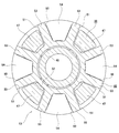
- FIG. 2 is a cross-sectional view taken along the line AA of FIG.
- FIG. 3 (A) is an end view showing an example torque transmission joint according to the embodiment of the present invention
- FIG. 3 (B) is a side view seen from the left side of FIG. 3 (A).
- (C) is a cross-sectional view taken along the line BB of FIG. 3 (A).
- FIG. 4 is a cross-sectional view taken along the line CC of FIG. 3 (B).
- FIG. 5 is a cross-sectional view taken along the line DD of FIG. 3 (C).
- FIG. 6 is a cross-sectional view taken along the line EE of FIG. 3 (C).
- FIG. 7 is a cross-sectional view taken along the line FF of FIG. 3 (C).
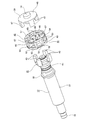
- FIG. 8 is a perspective view showing a torque transmission joint of one example of the embodiment of the present invention, in which a part thereof is disassembled and a second rotating member is supported and fixed to a worm.
- FIG. 9 is a perspective view showing an exploded view of an example torque transmission joint according to the embodiment of the present invention.
- 10 (A) is an end view showing the first rotating member
- FIG. 10 (B) is a side view seen from the left side of FIG. 10 (A)
- FIG. 10 (C) is FIG. 10 (C). It is a cross-sectional view of GG of A).
- FIG. 11 (A) is an end view showing the second rotating member
- FIG. 11 (B) is a side view seen from the right side of FIG. 11 (A)
- FIG. 11 (C) is FIG. 11 (C).
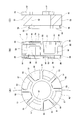
- 12 (A) is an end view showing the coupling
- FIG. 12 (B) is a side view seen from the right side of FIG. 12 (A)
- FIG. 12 (C) is FIG. 12 (A).
- FIG. 13 is an enlarged view of part J in FIG. 12 (B).
- 14 (A) is a side view of the elastic body
- FIG. 14 (B) is an end view seen from the right side of FIG. 14 (A)
- FIG. 14 (C) is a view of FIG. 14 (A). It is an end view seen from the left side.
- FIG. 15 is a diagram corresponding to FIG. 13 showing a modified example of one example of the embodiment.
- FIG. 16 is a partially cut side view showing a pinion assist type electric power steering device in which the electric motor with a worm reducer of the present invention can be incorporated.
- FIG. 17 is a partially cut side view showing a double pinion type electric power steering device in which the electric motor with a worm reducer of the present invention can be incorporated.
- Example of Embodiment] 1 to 14 (C) show an example of the embodiment of the present invention.
- This example is an example in which the electric motor with a worm reducer of the present invention is applied to a column assist type electric power steering device.
- the electric power steering device 1 the rotation of the steering wheel 2 is transmitted to the input shaft 4 of the steering gear unit 3. That is, the steering wheel 2 is supported and fixed to the rear end of the steering shaft 5, and the front end of the steering shaft 5 is connected to the rear end of the intermediate shaft 7 via the universal joint 6a. Has been done.
- the front end of the intermediate shaft 7 is connected to the input shaft 4 via another universal joint 6b.
- the rotation of the input shaft 4 is converted into a linear motion in the axial direction of the rack shaft (not shown) arranged in the width direction of the vehicle body in the steering gear unit 3.
- a steering angle is given to the steering wheels.
- the steering shaft 5 is rotatably supported inside the steering column 9 supported by the vehicle body.
- the electric power steering device 1 includes an electric motor 10 with a worm reducer.
- the electric power steering device 1 of this example is configured so that the force required for the driver to operate the steering wheel 2 can be reduced by applying the power of the electric motor 10 with a worm reducer to the steering shaft 5.
- the electric motor 10 with a worm reducer includes an electric motor 11, a worm reducer 12, and a torque transmission joint 13.
- the electric motor 11 has an output shaft 14.
- the electric motor 11 rotationally drives the output shaft 14 in both directions based on energization.
- the worm reducer 12 includes a housing 15, a worm wheel 16, and a worm 17.
- the housing 15 has a wheel accommodating portion 18 and a worm accommodating portion 19 having a central axis twisted with respect to the central axis of the wheel accommodating portion 18 and having an axial middle portion opened in the wheel accommodating portion 18. , Equipped with.
- the wheel accommodating portion 18 is supported and fixed to the front end of the steering column 9 so that its own central axis and the central axis of the steering column 9 are coaxial.
- the worm accommodating portion 19 is formed in a tubular shape and has openings at both ends in the axial direction.
- the opening on one side (right side in FIG. 2) of the worm accommodating portion 19 in the axial direction is closed by an electric motor 11 coupled and fixed to the housing 15.
- the opening on the other side (left side in FIG. 2) of the worm accommodating portion 19 in the axial direction is closed by the lid 20.
- FIG. 2 FIG. 3 (B), FIG. 3 (C), FIG. 8, FIG. 9, FIG. 10 (B), FIG. 10 (C), FIG. 11 (B), which is the base end side of the worm 17.
- FIGS. 11 (C), 12 (B) and 12 (C) Refers to the right side of FIGS. 11 (C), 12 (B) and 12 (C), and the other side in the axial direction is the tip side of the worm 17, which is the tip side of the worm 17, FIG. C), FIG. 8, FIG. 9, FIG. 10 (B), FIG. 10 (C), FIG. 11 (B), FIG. 11 (C), FIG. 12 (B) and the left side of FIG. 12 (C).
- the worm accommodating portion 19 has a cylindrical surface portion 21 having a cylindrical surface shape on the inner peripheral surface of one side portion in the axial direction, and a stepped portion facing one side in the axial direction at the other end portion in the axial direction of the cylindrical surface portion 21. Has 22. Further, the worm accommodating portion 19 has a cylindrical guide holding portion 23 on the inner peripheral surface of the other side portion in the axial direction.
- the worm wheel 16 has wheel teeth 24, which are helical gears, on the outer peripheral surface, and is rotatably supported inside the wheel accommodating portion 18.
- the worm wheel 16 is supported and fixed so as to rotate integrally with the steering shaft 5 around the front end portion of the steering shaft 5 rotatably supported inside the wheel accommodating portion 18.
- the worm wheel 16 of this example is formed by coupling and fixing an outer wheel element 26 made of synthetic resin having wheel teeth 24 on the outer peripheral surface around an inner wheel element 25 made of metal and having a circular plate shape.
- the worm 17 has screw-shaped worm teeth 27 that mesh with the wheel teeth 24 of the worm wheel 16 on the outer peripheral surface of the intermediate portion in the axial direction, and is rotatably supported inside the worm accommodating portion 19.
- the worm 17 is provided with a fitting cylinder portion 28 on one side in the axial direction with respect to the worm teeth 27.
- the fitting cylinder portion 28 is rotatably supported by the ball bearing 29 with respect to the cylindrical surface portion 21 of the worm accommodating portion 19.
- the outer ring of the ball bearing 29 is internally fitted to the cylindrical surface portion 21 in a state where displacement in the axial direction is prevented.
- the inner ring of the ball bearing 29 is fitted onto the fitting cylinder portion 28 without rattling.
- the inner ring of the ball bearing 29 has a flange portion 30 provided on a portion of the worm 17 adjacent to one side of the worm tooth 27 in the axial direction, and a torque transmission joint 13 externally fitted and fixed to the base end portion of the worm 17.
- the ball bearing 29 has a radial gap between the outer ring and the inner ring and the ball.
- the fitting cylinder portion 28 of the worm 17 is supported so as to be rotationally and oscillatingly displaced with respect to the cylindrical surface portion 21 of the worm accommodating portion 19.
- the structure of the worm 17 that supports the portion of the worm 17 located on one side in the axial direction with respect to the worm housing portion 19 so as to be able to rotate and swing is not limited to the above example. Various structures can be adopted.
- the worm 17 is provided with a small diameter tubular portion 33 at the tip portion.
- the small-diameter tubular portion 33 is supported by the support bearing 34 and the guide member 35 with respect to the guide holding portion 23 of the worm accommodating portion 19 so as to be able to rotate freely and to move in perspective with respect to the worm wheel 16.
- the inner ring of the support bearing 34 is externally fitted and fixed to the small diameter tubular portion 33.
- the outer ring of the support bearing 34 is held inside the guide member 35 so as to be able to move in perspective with respect to the worm wheel 16.
- the guide member 35 is held inside the guide holding portion 23 in a state where rotation is blocked.
- the guide member 35 locks the elastic ring 37 in the locking groove 36 provided on the outer peripheral surface over the entire circumference.
- the elastic ring 37 presses the portion of the outer peripheral surface of the guide member 35 far from the worm wheel 16 against the guide holding portion 23 to suppress rattling with respect to the guide holding portion 23.
- the support bearing 34 is elastically attached toward the worm wheel 16 side by a leaf spring 38 arranged at the end on the side far from the worm wheel 16 in the portion between the outer ring of the support bearing 34 and the guide member 35. It is being driven. As a result, backlash between the wheel teeth 24 and the worm teeth 27 is suppressed.
- the mechanism for elastically urging the tip of the worm 17 toward the worm wheel 16 side is not limited to the above example, and various structures can be adopted.
- the base end of the worm 17 is connected to the output shaft 14 of the electric motor 11 via a torque transmission joint 13 so as to be able to transmit torque.
- the torque transmission joint 13 includes a first rotating member 31, a second rotating member 39, a coupling 40, a first elastic body 41, and a second, which are coaxially arranged. It includes an elastic body 42.
- the first rotating member 31 has first convex portions 43 projecting toward one side in the axial direction at a plurality of locations in the circumferential direction on one side surface in the axial direction. Specifically, as shown in FIGS. 10A to 10C, the first rotating member 31 is directed from the cylindrical base portion 44 and the end portion of the base portion 44 on one side in the axial direction to the outside in the radial direction. From the radially outer end of the annular flange portion 45 protruding over the entire circumference and a plurality of locations (4 locations in the illustrated example) at equal intervals in the circumferential direction on one side surface in the axial direction of the flange portion 45 to one side in the axial direction. A first convex portion 43 projecting toward the surface is provided.
- the first convex portion 43 has a fan-shaped end face shape when viewed from the axial direction.
- the first rotating member 31 has a cylindrical projecting portion 46 projecting from the radially inner end of one side surface of the base 44 in the axial direction toward one side in the axial direction over the entire circumference.
- the protruding portion 46 is a portion for ensuring the fitting length of the first rotating member 31 with respect to the base end portion of the worm 17.
- the first rotating member 31 is externally fitted and fixed to the base end portion of the worm 17 so that torque can be transmitted.
- the first rotating member 31 is made of a synthetic resin, a sintered metal, or the like, which has higher rigidity (hard to be elastically deformed) than an elastic material such as an elastomer such as rubber constituting the first elastic body 41.
- the second rotating member 39 has second convex portions 47 protruding toward the other side in the axial direction at a plurality of locations in the circumferential direction on the other side surface in the axial direction.
- the second rotating member 39 has an annular plate-shaped base portion 48 and an axially other side surface of the base portion 48 at equal intervals in the circumferential direction. It is provided with a second convex portion 47 projecting from an end portion on the outer side in the radial direction at a plurality of locations (four locations in the illustrated example) toward the other side in the axial direction.
- the second convex portion 47 has a fan-shaped end face shape when viewed from the axial direction.
- the second rotating member 39 has a cylindrical projecting portion 49 projecting from the radially inner end of the axially other side surface of the base portion 48 toward the other side in the axial direction over the entire circumference.
- the protruding portion 49 is a portion for ensuring the fitting length of the second rotating member 39 with respect to the tip end portion of the output shaft 14 of the electric motor 11.
- the second rotating member 39 is externally fitted and fixed to the tip of the output shaft 14 of the electric motor 11 so that torque can be transmitted.
- the second rotating member 39 is made of a synthetic resin, a sintered metal, or the like, which has higher rigidity (hard to be elastically deformed) than an elastic material such as an elastomer such as rubber constituting the second elastic body 42.
- the second rotating member 39 may be made of the same material as the material constituting the first rotating member 31, or may be made of a different material.
- the coupling 40 has a first recess 50 and a second recess 51.
- the first concave portion 50 opens at a plurality of locations in the circumferential direction of the coupling 40 on the other side surface in the axial direction and the outer peripheral surface, and each of the first convex portions 43 of the first rotating member 31 causes a relative displacement in the circumferential direction. Engaged as possible.
- the second concave portion 51 is opened on one side surface in the axial direction and the outer peripheral surface at a plurality of locations in the circumferential direction deviating from the first concave portion 50 of the coupling 40 in the circumferential direction, and the second convex portion of the second rotating member 39.
- Each of the 47 has a second recess 51 that is engaged to allow relative displacement in the circumferential direction.
- the coupling 40 includes a cylindrical boss portion 52, a plurality of arm portions 53, and a plurality of first side plate portions 54. , A plurality of second side plate portions 55, and a plurality of second side plate portions 55.
- the shape of the boss portion 52 is not limited to a cylindrical shape, and may be a cylindrical shape.
- Each of the arm portions 53 is formed in the shape of a rectangular plate, and protrudes radially outward from a plurality of locations in the circumferential direction of the outer peripheral surface of the boss portion 52.
- the side surfaces of the arm 53 on both sides in the circumferential direction are formed of flat surfaces parallel to each other.
- Each of the first side plate portions 54 is a pair of arm portions 53 that protrude outward in the circumferential direction from a plurality of circumferential directions on the outer peripheral surface of one end of the boss portion 52 in the axial direction and are adjacent to each other in the circumferential direction. The ends on one side in the axial direction are connected to each other.
- Each of the first side plate portions 54 has a fan-shaped end face shape when viewed from the axial direction.
- Each of the second side plate portions 55 projects outward in the radial direction from a plurality of circumferential directions deviated from the first side plate portion 54 in the outer peripheral surface of the end portion on the other side in the axial direction of the boss portion 52.
- the ends of the pair of arm portions 53 adjacent to each other in the circumferential direction on the other side in the axial direction are connected to each other. That is, the first side plate portion 54 and the second side plate portion 55 are alternately arranged on the outer peripheral surface of the boss portion 52 in the circumferential direction.
- Each of the second side plate portions 55 has a fan-shaped end face shape when viewed from the axial direction.
- Each of the first recesses 50 is a pair in which the outer peripheral surface of the boss portion 52, the other side surfaces in the axial direction of the first side plate portion 54, and the end portion on one side in the axial direction are connected to each of the first side plate portions 54. It is defined by the circumferential side surfaces of the arm 53 facing each other.
- Each of the first convex portions 43 of the first rotating member 31 is engaged with each of the first concave portions 50 so as to be relatively displaced in the circumferential direction. That is, with the first convex portion 43 arranged inside the first concave portion 50, between the inner side surfaces of the first concave portion 50 on both sides in the circumferential direction and the outer surfaces of the first convex portion 43 on both sides in the circumferential direction. There is a gap in the circumferential direction between at least one of the portions. Further, there is a radial gap between the radial inner surface of the first convex portion 43 and the outer peripheral surface of the boss portion 52.
- Each of the second recesses 51 is a pair in which the outer peripheral surface of the boss portion 52, one side surface of the second side plate portion 55 in the axial direction, and the end portions of the second side plate portion 55 on the other side in the axial direction are connected to each other. It is defined by the circumferential side surfaces of the arm portions 53 facing each other.
- Each of the second convex portions 47 of the second rotating member 39 is engaged with each of the second concave portions 51 so as to be relatively displaced in the circumferential direction. That is, with the second convex portion 47 arranged inside the second concave portion 51, between the inner side surfaces of the second concave portion 51 on both sides in the circumferential direction and the outer surfaces of the second convex portion 47 on both sides in the circumferential direction. There is a gap in the circumferential direction between at least one of the portions. Further, there is a radial gap between the radial inner surface of the second convex portion 47 and the outer peripheral surface of the boss portion 52.
- each of the first convex portion 43 of the first rotating member 31 and each of the second convex portion 47 of the second rotating member 39 are alternately arranged in the circumferential direction, and the first The arm portion 53 of the coupling 40 is arranged so as to be displaced in the circumferential direction between the outer surface of the convex portion 43 in the circumferential direction and the outer surface of the second convex portion 47 in the circumferential direction.
- the first convex portion 43 and the second convex portion 47 are arranged. At least partly overlaps in the axial direction. That is, as shown in FIG. 4, in the CC cross section of FIG. 3B, the first convex portion 43 and the second convex portion 47 face each other in the circumferential direction. Therefore, even if the coupling 40 is damaged, the torque transmission function can be maintained by the first convex portion 43 and the second convex portion 47.
- the coupling 40 has a first support portion 56 for supporting the first elastic body 41 on each axially other side surface of the second side plate portion 55, and each of the first side plate portions 54.
- a second support portion 57 for supporting the second elastic body 42 is provided on one side surface in the axial direction.
- Each of the first support portions 56 has a fan-shaped end face shape when viewed from the axial direction, and protrudes from the other side surface in the axial direction of the second side plate portion 55 toward the other side in the axial direction.
- each of the first support portions 56 has a first locking groove 58 extending in the circumferential direction on the outer surface in the radial direction.
- Each of the second support portions 57 has a fan-shaped end face shape when viewed from the axial direction, and protrudes from one side surface in the axial direction of the first side plate portion 54 toward one side in the axial direction.
- each of the second support portions 57 has a second locking groove 59 extending in the circumferential direction on the outer surface in the radial direction.
- the coupling 40 has higher rigidity (difficult to elastically deform) than the materials constituting the first elastic body 41 and the second elastic body 42, and the first convex portion 43 and the second rotating member of the first rotating member 31. It is made of a material that can suppress the impact at the time of contact with the second convex portion 47 of 39.
- the coupling 40 is made of polyphenylene sulfide (PPS), polyetheretherketone (PEEK) or nylon, or a resin obtained by mixing reinforcing fibers with these, an elastomer such as rubber, or a woven cloth. It can be made of reinforced belt material or the like.
- the first elastic body 41 has a plurality of first elastic pieces 60 sandwiched in the circumferential direction between each of the first convex portions 43 of the first rotating member 31 and the coupling 40.
- the first elastic body 41 includes a plurality of (eight in the illustrated example) first elastic pieces 60 and the circumferential direction.
- the first inner diameter side connection piece 61 and the first outer diameter side connection piece 62 which are alternately arranged one by one (four in the illustrated example), and the first combination of a plurality (four in the illustrated example).
- a stop piece 63 and a stop piece 63 are provided.
- Each of the first elastic pieces 60 is formed in a rectangular columnar shape and is arranged in the radial direction.
- Each of the first inner diameter side connecting pieces 61 connects the radially inner ends of a pair of first elastic pieces 60 adjacent to each other in the circumferential direction.
- Each of the first inner diameter side connecting pieces 61 has an arc-shaped end face shape when viewed from the axial direction.
- Each of the first outer diameter side connection pieces 62 is arranged at a position deviated from the first inner diameter side connection piece 61 in the circumferential direction, and is radially outside of a pair of first elastic pieces 60 adjacent to each other in the circumferential direction. The ends of the are connected to each other.
- Each of the first outer diameter side connecting pieces 62 has an arc-shaped end face shape when viewed from the axial direction.
- Each of the first locking pieces 63 is arranged at a position where the first inner diameter side connection piece 61 and the phase of the first inner diameter side connection piece 61 coincide with each other in the circumferential direction, in other words, at a position deviated from the first outer diameter side connection piece 62 in the circumferential direction.
- the radial outer ends of the pair of first elastic pieces 60 adjacent to each other in the circumferential direction are connected to each other.
- Each of the first locking pieces 63 has an arcuate end face shape when viewed from the axial direction. That is, the first outer diameter side connecting piece 62 and the first locking piece 63 are alternately arranged in the circumferential direction so as to form an annular shape as a whole.
- the axial thickness of the first locking piece 63 is made smaller than the axial thickness of the first elastic piece 60, the first inner diameter side connection piece 61, and the first outer diameter side connection piece 62.
- the axial thickness of the first locking piece 63 is set to about half the axial thickness of the first elastic piece 60, the first inner diameter side connection piece 61, and the first outer diameter side connection piece 62.
- the axial thicknesses of the first elastic piece 60, the first inner diameter side connection piece 61, and the first outer diameter side connection piece 62 are all the same. That is, the other side surface in the axial direction of the first locking piece 63 of the first elastic body 41 is located on one side in the axial direction with respect to the other side surface in the axial direction of the remaining portion.
- the circumferential dimension of the portion between the pair of first elastic pieces 60 in which the radial outer end is connected to the first outer diameter side connecting piece 62 is the circumference of the first recess 50 of the coupling 40. Smaller than the directional dimension.
- the first elastic body 41 is a substantially trapezoidal annular first supported body composed of a pair of first elastic pieces 60 adjacent to each other in the circumferential direction, a first inner diameter side connecting piece 61, and a first locking piece 63. It has a part 73. Then, by engaging (outer fitting) each of the first supported portions 73 with each of the first supporting portions 56, the first elastic body 41 is supported by the end portion of the coupling 40 on the other side in the axial direction. ing. Specifically, the first locking piece 63 is locked in the first locking groove 58, and the first support portion 56 is elastically sandwiched from both sides in the circumferential direction by the pair of first elastic pieces 60. By elastically contacting the radial outer surface of the first inner diameter side connection piece 61 with the radial inner surface of the first support portion 56, the first elastic body 41 is brought into contact with the axially other end of the coupling 40. I support the club.
- the first convex portion of the first rotating member 31 is located between the pair of first elastic pieces 60, which are connected to the first outer diameter side connecting piece 62 at the outer end in the radial direction. 43 is inserted. That is, each of the first elastic pieces 60 has a circumferential side surface of the first convex portion 43 of the first rotating member 31 and a circumferential side surface of the first support portion 56 of the coupling 40. It is sandwiched between.
- the radial outer surface of the first convex portion 43 may be in contact with the radial inner surface of the first outer diameter side connection piece 62, or may be non-contact.
- the first elastic body 41 has a plurality of (four in the illustrated example) first protrusions 64 protruding toward the other side in the axial direction on the other side surface in the axial direction.
- the first elastic body 41 has a first protrusion 64 at the center position in the circumferential direction of each axially other side surface of the first inner diameter side connecting piece 61.
- each of the first protrusions 64 Elastically contacts one side surface of the flange portion 45 of the first rotating member 31 in the axial direction.
- the second elastic body 42 has a plurality of second elastic pieces 65 sandwiched in the circumferential direction between each of the second convex portions 47 of the second rotating member 39 and the coupling 40.
- the second elastic body 42 the one having the same specifications as the first elastic body 41 (the one having the same shape, dimensions, and material) is used. That is, as shown in FIGS. 14 (A) to 14 (C), the second elastic bodies 42 are alternately plural with a plurality of (8 in the illustrated example) second elastic pieces 65 in the circumferential direction.
- the second elastic body 42 is a substantially trapezoidal annular second supported body composed of a pair of second elastic pieces 65 adjacent to each other in the circumferential direction, a second inner diameter side connecting piece 66, and a second locking piece 68. It has a part 74. Then, by engaging (outer fitting) each of the second supported portions 74 with each of the second supporting portions 57, the second elastic body 42 is supported by one end of the coupling 40 in the axial direction. There is. Specifically, the second locking piece 68 is locked in the second locking groove 59, and the second support portion 57 is elastically sandwiched from both sides in the circumferential direction by the pair of second elastic pieces 65. By elastically contacting the radial outer surface of the second inner diameter side connection piece 66 with the radial inner surface of the second support portion 57, the second elastic body 42 is brought into contact with the axial one-side end of the coupling 40. Supports.
- the second convex portion of the second rotating member 39 is located between the pair of second elastic pieces 65, which are connected to the second outer diameter side connecting piece 67 at the outer end in the radial direction. 47 is inserted. That is, each of the second elastic pieces 65 is between the respective circumferential side surfaces of the second convex portion 47 of the second rotating member 39 and the respective circumferential side surfaces of the second support portion 57 of the coupling 40. It is sandwiched between.
- the radial outer surface of the second convex portion 47 may be in contact with the radial inner surface of the second outer diameter side connection piece 67, or may be non-contact.
- the second elastic body 42 has a plurality of (four in the illustrated example) second protrusions 69 protruding toward one side in the axial direction on one side surface in the axial direction.
- the second elastic body 42 has a second protrusion 69 at the center position in the circumferential direction of each side surface of the second inner diameter side connecting piece 66 in the axial direction.
- each of the second protrusions 69 Elastically contacts the other side surface of the base 48 of the second rotating member 39 in the axial direction.
- the second rotation is accompanied by the rotation of the output shaft 14.
- the outer surface of the second convex portion 47 of the member 39 in the circumferential direction passes through the second elastic piece 65 of the second elastic body 42, and the outer surface of the second support portion 57 of the coupling 40 is in the circumferential direction. Press on.
- the outer surface of the first support portion 56 of the coupling 40 in the circumferential direction passes through the first elastic piece 60 of the first elastic body 41, and the first rotating member 31 first.
- the outer surface of the convex portion 43 in the circumferential direction is pressed. In this way, the rotational torque of the output shaft 14 is transmitted to the worm 17.
- the second elastic piece 65 of the second elastic body 42 goes out of the circumferential direction of the second support portion 57 of the coupling 40.
- the first elastic piece 60 of the first elastic body 41 is elastically crushed in the circumferential direction between the side surface and the outer surface of the second convex portion 47 of the second rotating member 39 in the circumferential direction. It is elastically crushed in the circumferential direction between the outer surface of the first support portion 56 of the coupling 40 in the circumferential direction and the outer surface of the first convex portion 43 of the first rotating member 31 in the circumferential direction.
- the outer surface of the second convex portion 47 of the second rotating member 39 in the circumferential direction and the inner surface of the second concave portion 51 of the coupling 40 in the circumferential direction are in direct contact with each other, and the first The outer surface of the first convex portion 43 of the rotating member 31 in the circumferential direction and the inner surface of the first concave portion 50 of the coupling 40 in the circumferential direction directly abut each other. Since the momentum of these abuttals is weakened by the first elastic body 41 and the second elastic body 42, the outer surface of the second convex portion 47 in the circumferential direction and the circle of the second concave portion 51 accompany the abutting.
- Abnormal noise such as jarring rattling noise is heard at the contact portion with the inner surface in the circumferential direction and the contact portion between the outer surface in the circumferential direction of the first convex portion 43 and the inner surface in the circumferential direction of the first concave portion 50. It can be prevented from occurring. Further, in this state, most of the rotational torque of the output shaft 14 is transmitted to the coupling 40 from the contact portion between the outer surface of the second convex portion 47 in the circumferential direction and the inner surface of the second concave portion 51 in the circumferential direction. Most of the torque transmitted to the coupling 40 is transmitted to the worm 17 from the contact portion between the outer surface of the first convex portion 43 in the circumferential direction and the inner surface of the first concave portion 50 in the circumferential direction. Will be done.
- the cups do not match.
- the output shaft 14 and the worm 17 are tilted by the ring 40 with respect to the central axis of the worm 17 and / or the central axis of the output shaft 14 while elastically deforming the first elastic body 41 and / or the second elastic body 42.
- the torque can be smoothly transmitted to and from the vehicle.
- the first elastic body 41 has a first protrusion 64 at the center position in the circumferential direction of each axial and other side surface of the first inner diameter side connecting piece 61.
- first protrusion 64 When the central axis of the coupling 40 coincides with the central axis of the worm 17 and / or the central axis of the output shaft 14 (when the coupling 40 is not tilted with respect to the axial direction), each of the first protrusions 64 Does not come into contact with one side surface of the flange portion 45 of the first rotating member 31 in the axial direction.
- each of the first protrusions 64 Elastically contacts one side surface of the flange portion 45 of the first rotating member 31 in the axial direction. Therefore, when the coupling 40 is tilted with respect to the central axis of the worm 17 and / or the central axis of the output shaft 14, one side surface of the flange portion 45 of the first rotating member 31 collides with the first protrusion 64.
- the speed can be reduced (slowened) as compared with the case where the first protrusion 64 is arranged in the radial outer portion. Therefore, it is possible to suppress the abnormal noise caused by the one side surface of the flange portion 45 of the first rotating member 31 colliding with the first protrusion 64 in the axial direction.
- the second elastic body 42 has a second protrusion 69 at the center position in the circumferential direction of each axially other side surface of the second inner diameter side connecting piece 66.
- each of the second protrusions 69 is a second rotating member. Elastically contacts the other side surface of the base 48 of 39 in the axial direction. Therefore, when the coupling 40 is tilted with respect to the central axis of the worm 17 and / or the central axis of the output shaft 14, the speed at which the other side surface of the base 48 of the second rotating member 39 collides with the second protrusion 69. Can be made smaller (slower). Therefore, it is possible to suppress the abnormal noise caused by the axial other side surface of the base portion 48 of the second rotating member 39 colliding with the second protrusion 69.
- the rigidity of the first elastic body and the second elastic body may be different from each other, or the circumferential gap between the first convex portion and the first concave portion and the second convex portion may be used. It is also possible to make the circumferential gap between the second recess and the second recess different from each other.
- the magnitude of the transmission torque that collides with the inner surface in the circumferential direction can be made different.
- the torque transmission characteristics between the output shaft of the electric motor and the worm can be divided into multiple stages, and the operation feeling of the steering wheel can be improved.
- each of the first recesses 50a has a circumferential width dimension between the axial other side portions of the inner side surfaces facing each other in the circumferential direction from the circumferential width dimension between the axial one side portions.
- Each of the second recesses 51a has a circumferential width dimension between the axial one side portions of the inner side surfaces facing each other in the circumferential direction, and a circumferential width dimension between the axial other side portions. Is larger than.
- the inner surfaces on both sides of the first concave portion 50a in the circumferential direction are opposed to each other.
- a step portion 72a is formed which is inclined in a direction away from each other toward the other side in the axial direction.
- the inner side surfaces of the second concave portion 51a on both sides in the circumferential direction (the circumferential side surfaces of the pair of arm portions 53a facing each other, in which the end portions on the other side in the axial direction are connected to each of the second side plate portions 55).
- a step portion 72b is formed in a portion of the intermediate portion in the axial direction located on one side in the axial direction with respect to the step portion 72a, which is inclined in a direction away from each other toward one side in the axial direction.
- the circumferential width dimension of each of the inner side surfaces of the second recess 51 in the axial direction is made larger than the circumferential width dimension of the other side portions in the axial direction.
- one side portion in the axial direction (the portion surrounded by the chain line ⁇ in FIG. 15) of the inner side surface in the circumferential direction of the first recess 50a is the first.
- One convex portion 43 is in contact with the outer surface in the circumferential direction
- the other side portion in the axial direction (the portion surrounded by the chain line ⁇ in FIG. 15) of the inner side surface in the circumferential direction of the second concave portion 51a is the second convex portion. It comes into contact with the outer surface of the portion 47 in the circumferential direction.
- the circle of the first convex portion 43 is formed.
- the contact position of the inner side surface of the first concave portion 50a with respect to the outer surface in the circumferential direction can be set to be near the central position in the axial direction of the coupling 40a, and the contact position with respect to the outer surface of the second convex portion 47 in the circumferential direction.
- the contact position of the inner surface of the second recess 51a in the circumferential direction can be set to be near the central position in the axial direction of the coupling 40a.
- the coupling 40a when the coupling 40a is tilted with respect to the central axis of the worm 17 and / or the central axis of the output shaft 14, the coupling 40a can be tilted about the vicinity of the central position in the axial direction. From this aspect as well, torque can be stably transmitted between the output shaft 14 and the worm 17 via the torque transmission joint 13.
- the circumferential width dimension of the other side portions in the axial direction of the inner side surfaces of the first concave portions facing each other in the circumferential direction is made constant over the axial direction, and the shaft. While making it larger than the circumferential width dimension of each of the directional one-sided portions, the circumferential width dimension of each of the axially one-sided portions of the inner side surfaces of the second recesses facing each other in the circumferential direction is constant over the axial direction. It is also possible to make it larger than the circumferential width dimension between the other side portions in the axial direction.
- the electric motor with a worm reducer of the present invention can be incorporated not only in a column assist type electric power steering device but also in an electric power steering device having various structures.
- the electric motor with a worm reducer of the present invention when incorporated into the pinion-assisted electric power steering device 1a as shown in FIG. 16, the worm is attached to the input shaft 4a of the steering gear unit 3a.
- the worm wheel 16 of the speed reducer 12 is supported and fixed.
- the electric motor with a worm reducer of the present invention When the electric motor with a worm reducer of the present invention is incorporated into the double pinion type electric power steering device 1b as shown in FIG. 17, it is located at a portion deviated from the input shaft 4 of the steering gear unit 3 in the width direction of the vehicle. , The rotating shaft 70 to which the worm wheel 16 is fitted and fixed is arranged, and the pinion teeth provided at the tip of the rotating shaft 70 are engaged with the teeth of the rack 71 constituting the steering gear unit 3.
- the electric motor with a worm reducer of the present invention can be incorporated not only in an electric power steering device but also in various mechanical devices.
- the torque transmission joint of the present invention is not limited to the electric motor with a worm reducer, and can be used by being incorporated between a pair of rotating shafts arranged coaxially with each other in the torque transmission path of various mechanical devices. it can.
Abstract
A torque transfer joint comprises: a first elastic body having a plurality of first elastic pieces that are pinched, respectively, in the circumferential direction between a first projecting part and a coupling; and a second elastic body having a plurality of second elastic pieces that are pinched, respectively, in the circumferential direction between a second projecting part and the coupling.
Description
本発明は、各種機械装置に組み込まれて、一対の回転部材同士の間でトルクを伝達するために利用するトルク伝達継手、および、トルク伝達継手を備えるウォーム減速機付電動モータに関する。
The present invention relates to a torque transmission joint incorporated in various mechanical devices and used to transmit torque between a pair of rotating members, and an electric motor with a worm reducer provided with the torque transmission joint.
パワーステアリング装置は、運転者がステアリングホイールを操作するのに要する力の軽減を図れるため、広く使用されている。パワーステアリング装置には、補助動力源として電動モータを利用する電動パワーステアリング装置と、補助動力源として油圧を利用する油圧パワーステアリング装置と、の2種類がある。このうちの電動パワーステアリング装置は、油圧パワーステアリング装置に比べて、小型かつ軽量に構成でき、補助動力の大きさの制御が容易で、しかもエンジンの動力損失が少ないなどの利点があり、利用頻度が増えている。
The power steering device is widely used because it can reduce the force required for the driver to operate the steering wheel. There are two types of power steering devices: an electric power steering device that uses an electric motor as an auxiliary power source and a hydraulic power steering device that uses a flood control as an auxiliary power source. Of these, the electric power steering device has advantages such as being smaller and lighter than the hydraulic power steering device, being able to easily control the size of the auxiliary power, and having less power loss of the engine, and is used frequently. Is increasing.
電動パワーステアリング装置では、ステアリングホイールの操作に基づき回転する操舵用回転軸に対して、電動モータの補助動力を減速機を介して付与する。減速機としては、大きな減速比が得られるなどの理由から、ウォーム減速機が広く使用されている。
In the electric power steering device, auxiliary power of the electric motor is applied to the steering rotating shaft that rotates based on the operation of the steering wheel via the reduction gear. As a speed reducer, a worm speed reducer is widely used because a large reduction ratio can be obtained.
ただし、ウォーム減速機を構成するウォームホイールとウォームとの噛合部には、不可避のバックラッシュが存在しているため、ウォームホイールの回転方向が変化する際に、歯打ち音を発生させやすいという問題がある。
However, since there is an unavoidable backlash in the meshing part between the worm wheel and the worm that make up the worm reducer, there is a problem that a rattling noise is likely to be generated when the rotation direction of the worm wheel changes. There is.
日本国特開2004-306898号公報(特許文献1)には、ウォームをハウジングに対して回転自在に支持するための一対の軸受のうち、ウォームの先端側に配置された軸受とハウジングとの間に、ばねを含んで構成される付勢部材を配置し、ウォームの先端部をウォームホイールに向けて付勢する構造が開示されている。このような構造によれば、噛合部のバックラッシュを抑えることができ、ウォームホイールとウォームとの噛合部での歯打ち音の発生を抑制できる。
According to Japanese Patent Application Laid-Open No. 2004-306898 (Patent Document 1), among a pair of bearings for rotatably supporting a worm with respect to a housing, between the bearing arranged on the tip side of the worm and the housing. Discloses a structure in which an urging member including a spring is arranged and the tip of the worm is urged toward the worm wheel. According to such a structure, the backlash of the meshing portion can be suppressed, and the generation of rattling noise at the meshing portion between the worm wheel and the worm can be suppressed.
日本国特開2004-306898号公報に記載の構造では、電動モータの出力軸の先端部に備えられたスプライン軸部と、ウォームの基端部に備えられたスプライン孔と、をスプライン係合させることで、出力軸とウォームとがトルクの伝達を可能に接続されている。スプライン軸部とスプライン孔とが、円周方向に関する隙間なく(バックラッシュなしで)スプライン係合していれば、出力軸とウォームとの接続部(スプライン係合部)で、異音が発生することはない。しかしながら、日本国特開2004-306898号公報に記載の構造では、付勢部材により、ウォームの先端部をウォームホイールに向けて付勢すべく、ウォームを揺動変位させる必要があるため、スプライン係合部のバックラッシュを完全になくすことはできない。したがって、異音の発生を抑えるためには改良の余地がある。
In the structure described in Japanese Patent Application Laid-Open No. 2004-306898, the spline shaft portion provided at the tip end portion of the output shaft of the electric motor and the spline hole provided at the base end portion of the worm are spline-engaged. As a result, the output shaft and the worm are connected so that torque can be transmitted. If the spline shaft and the spline hole are spline-engaged without a gap in the circumferential direction (without backlash), an abnormal noise is generated at the connection between the output shaft and the worm (spline engagement). There is no such thing. However, in the structure described in Japanese Patent Application Laid-Open No. 2004-306898, it is necessary to swing and displace the worm so that the tip of the worm is urged toward the worm wheel by the urging member. The backlash of the joint cannot be completely eliminated. Therefore, there is room for improvement in order to suppress the generation of abnormal noise.
本発明は、上述のような事情に鑑み、一対の回転部材の中心軸同士が互いに不一致になっても、前記一対の回転部材同士の間でのトルク伝達を円滑に行うことができ、かつ、前記一対の回転部材同士の間での異音の発生を防止することができる、トルク伝達継手の構造を実現することを目的としている。
In view of the above circumstances, the present invention can smoothly transmit torque between the pair of rotating members even if the central axes of the pair of rotating members do not match each other. It is an object of the present invention to realize a structure of a torque transmission joint capable of preventing the generation of abnormal noise between the pair of rotating members.
本発明のトルク伝達継手は、
軸方向片側面の円周方向複数箇所に、軸方向片側に向けて突出する第1凸部を有する、第1回転部材と、
軸方向他側面の円周方向複数箇所に、軸方向他側に向けて突出する第2凸部を有する、第2回転部材と、
円周方向複数箇所に、少なくとも軸方向他側面に開口し、前記第1凸部のそれぞれが円周方向の相対変位を可能に係合される第1凹部を有し、かつ、前記第1凹部から円周方向に外れた円周方向複数箇所に、少なくとも軸方向片側面に開口し、前記第2凸部のそれぞれが円周方向の相対変位を可能に係合される第2凹部を有する、カップリングと、
前記第1凸部のそれぞれと、前記カップリングとの間で周方向に挟持される、複数個の第1弾性片を有する、第1弾性体と、
前記第2凸部のそれぞれと、前記カップリングとの間で周方向に挟持される、複数個の第2弾性片を有する、第2弾性体と、
を備える。 The torque transmission joint of the present invention
A first rotating member having first convex portions protruding toward one side in the axial direction at a plurality of locations in the circumferential direction on one side surface in the axial direction.
A second rotating member having second convex portions protruding toward the other side in the axial direction at a plurality of locations in the circumferential direction on the other side surface in the axial direction.
The first concave portion is opened at a plurality of locations in the circumferential direction at least on the other side surface in the axial direction, and each of the first convex portions is engaged with a relative displacement in the circumferential direction. Each of the second convex portions has a second concave portion that is open at least on one side surface in the axial direction and is engaged with each other so as to enable relative displacement in the circumferential direction at a plurality of locations in the circumferential direction deviating from the circumferential direction. Coupling and
A first elastic body having a plurality of first elastic pieces sandwiched in the circumferential direction between each of the first convex portions and the coupling.
A second elastic body having a plurality of second elastic pieces sandwiched in the circumferential direction between each of the second convex portions and the coupling.
To be equipped.
前記カップリングは、
円筒状または円柱状のボス部と、
前記ボス部の外周面の円周方向複数箇所から径方向外側に向けて突出する、複数個の腕部と、
前記ボス部の軸方向片側の端部外周面の円周方向複数箇所から、径方向外側に向けて突出し、かつ、円周方向に隣り合う一対の前記腕部の軸方向片側の端部同士を円周方向に接続する、複数個の第1側板部と、
前記ボス部の軸方向他側の端部外周面のうち、前記第1側板部から円周方向に外れた円周方向複数箇所から径方向外側に向けて突出し、かつ、円周方向に隣り合う一対の前記腕部の軸方向他側の端部同士を円周方向に接続する、複数個の第2側板部と、
を備えることができる。
この場合、前記第1凹部のそれぞれは、前記ボス部の外周面と、前記第1側板部のそれぞれの軸方向他側面と、前記第1側板部のそれぞれに軸方向片側の端部を接続した、一対の前記腕部の互いに対向する円周方向側面とにより画成され、および、前記第2凹部のそれぞれは、前記ボス部の外周面と、前記第2側板部のそれぞれの軸方向片側面と、前記第2側板部のそれぞれに軸方向他側の端部を接続した、一対の前記腕部の互いに対向する円周方向側面とにより画成される。 The coupling is
Cylindrical or cylindrical boss and
A plurality of arms protruding outward in the radial direction from a plurality of circumferential directions on the outer peripheral surface of the boss portion.
A pair of axially one-sided ends of the pair of arms projecting outward in the radial direction from a plurality of circumferential directions on the outer peripheral surface of one end of the boss portion in the axial direction. With a plurality of first side plates connected in the circumferential direction,
Of the outer peripheral surfaces of the ends of the boss portion on the other side in the axial direction, the peripheral surfaces protrude outward in the circumferential direction from a plurality of locations in the circumferential direction deviating from the first side plate portion in the circumferential direction, and are adjacent to each other in the circumferential direction. A plurality of second side plate portions that connect the ends of the pair of arms on the other side in the axial direction in the circumferential direction.
Can be provided.
In this case, each of the first recesses is connected to the outer peripheral surface of the boss portion, the other side surfaces of the first side plate portion in the axial direction, and the end portion on one side in the axial direction to each of the first side plate portions. , The pair of arm portions facing each other in the circumferential direction, and each of the second recesses is an outer peripheral surface of the boss portion and one axial side surface of the second side plate portion. And the peripheral side surfaces of the pair of the arm portions facing each other, in which the ends on the other side in the axial direction are connected to each of the second side plate portions.
前記カップリングは、前記第2側板部のそれぞれの軸方向他側面に、前記第1弾性体を支持するための第1支持部を有し、かつ、前記第1側板部のそれぞれの軸方向片側面に、前記第2弾性体を支持するための第2支持部を有することができる。
The coupling has a first support portion for supporting the first elastic body on each axial other side surface of the second side plate portion, and each axial piece of the first side plate portion. A second support portion for supporting the second elastic body can be provided on the side surface.
前記第1弾性体は、円周方向に関して交互に複数ずつ配置された、第1内径側接続片および第1外径側接続片と、第1係止片とをさらに備えることができる。
この場合、前記第1内径側接続片は、円周方向に隣り合う一対の前記第1弾性片の径方向内側の端部同士を接続し、前記第1外径側接続片は、円周方向に隣り合う一対の前記第1弾性片の径方向外側の端部同士を接続し、前記第1係止片は、前記第1内径側接続片により径方向内側の端部同士を接続された一対の前記第1弾性片の径方向外側の接続部同士を接続する。
前記第1弾性体は、円周方向に隣り合う一対の前記第1弾性片と、前記第1内径側接続片と、前記第1係止片とからなる第1被支持部を、前記第1支持部に外嵌することで、前記カップリングに支持される。
前記第2弾性体は、円周方向に関して交互に複数ずつ配置された、第2内径側接続片および第2外径側接続片と、第2係止片とをさらに備えることができる。
この場合、前記第2内径側接続片は、円周方向に隣り合う一対の前記第2弾性片の径方向内側の端部同士を接続し、前記第2外径側接続片は、円周方向に隣り合う一対の前記第2弾性片の径方向外側の端部同士を接続し、前記第2係止片は、前記第2内径側接続片により径方向内側の端部同士を接続された一対の前記第2弾性片の径方向外側の端部同士を接続する。 前記第2弾性体は、円周方向に隣り合う一対の前記第2弾性片と、前記第2内径側接続片と、前記第2係止片とからなる第2被支持部を、前記第2支持部に外嵌することで、前記カップリングに支持される。 The first elastic body may further include a first inner diameter side connecting piece, a first outer diameter side connecting piece, and a first locking piece, which are alternately arranged in a plurality in the circumferential direction.
In this case, the first inner diameter side connecting piece connects the radially inner ends of the pair of the first elastic pieces adjacent to each other in the circumferential direction, and the first outer diameter side connecting piece is in the circumferential direction. A pair of adjacent first elastic pieces are connected to each other on the radial outer ends, and the first locking piece is a pair in which the radial inner ends are connected by the first inner diameter side connecting piece. The connecting portions on the outer side in the radial direction of the first elastic piece are connected to each other.
The first elastic body has a first supported portion composed of a pair of the first elastic pieces adjacent to each other in the circumferential direction, the first inner diameter side connecting piece, and the first locking piece. By externally fitting to the support portion, it is supported by the coupling.
The second elastic body may further include a second inner diameter side connecting piece, a second outer diameter side connecting piece, and a second locking piece, which are alternately arranged in a plurality in the circumferential direction.
In this case, the second inner diameter side connecting piece connects the radially inner ends of the pair of second elastic pieces adjacent to each other in the circumferential direction, and the second outer diameter side connecting piece is in the circumferential direction. A pair of adjacent ends of the second elastic piece connected to each other on the outer side in the radial direction, and the second locking piece connected to each other on the inner side in the radial direction by the second inner diameter side connecting piece. The radial outer ends of the second elastic piece are connected to each other. The second elastic body has a second supported portion composed of a pair of the second elastic pieces adjacent to each other in the circumferential direction, the second inner diameter side connecting piece, and the second locking piece. By externally fitting to the support portion, it is supported by the coupling.
前記カップリングは、前記第1支持部の径方向外側面に、円周方向に伸長する、前記第1係止片を係止するための第1係止溝を有し、かつ、前記第2支持部の径方向外側面に、円周方向に伸長する、前記第2係止片を係止するための第2係止溝を有することができる。
The coupling has a first locking groove extending in the circumferential direction for locking the first locking piece on the radial outer surface of the first support portion, and the second locking groove. A second locking groove for locking the second locking piece, which extends in the circumferential direction, can be provided on the radial outer surface of the support portion.
前記第1凹部は、互いに円周方向に対向する内側面のうちの軸方向他側部分同士の円周方向幅寸法を軸方向片側部分同士の円周方向幅寸法よりも大きくし、および、前記第2凹部は、互いに円周方向に対向する内側面のうちの軸方向片側部分同士の円周方向幅寸法を軸方向他側部分同士の円周方向幅寸法よりも大きくすることができる。
In the first recess, the circumferential width dimension between the axially other side portions of the inner side surfaces facing each other in the circumferential direction is made larger than the circumferential width dimension between the axial one side portions, and the first recess is described. The second concave portion can have a circumferential width dimension between the axial one-sided portions of the inner side surfaces facing each other in the circumferential direction larger than the circumferential width dimension between the axial other side portions.
前記第1弾性片が円周方向に弾性的に押し潰され、前記第1凹部の円周方向内側面と前記第1凸部の円周方向外側面とが当接し、かつ、前記第2弾性片が円周方向に弾性的に押し潰され、前記第2凹部の円周方向内側面と前記第2凸部の円周方向外側面とが当接した状態において、前記第1凹部の円周方向内側面のうちで前記第1凸部の円周方向外側面と当接する部分の軸方向他側部分と、前記第2凹部の円周方向内側面のうちで前記第2凸部の円周方向外側面と当接する部分の軸方向片側部分とが円周方向に重畳していることが好ましい。
The first elastic piece is elastically crushed in the circumferential direction, the inner surface of the first concave portion in the circumferential direction and the outer surface of the first convex portion in the circumferential direction are in contact with each other, and the second elastic piece is elastic. The circumference of the first recess is in a state where the piece is elastically crushed in the circumferential direction and the inner surface of the second concave portion in the circumferential direction and the outer surface of the second convex portion in the circumferential direction are in contact with each other. Of the inner side surfaces in the direction, the other side portion in the axial direction of the portion that comes into contact with the outer surface in the circumferential direction of the first convex portion, and the circumference of the second convex portion among the inner side surfaces in the circumferential direction of the second concave portion. It is preferable that one side portion in the axial direction of the portion that abuts on the outer surface in the direction overlaps in the circumferential direction.
前記第1弾性体は、軸方向他側面に、軸方向他側に向けて突出する、複数個の第1突起を有し、および、前記第2弾性体は、軸方向片側面に、軸方向片側に向けて突出する、複数個の第2突起を有することができる。
The first elastic body has a plurality of first protrusions protruding toward the other side in the axial direction on the other side surface in the axial direction, and the second elastic body has an axial direction on one side surface in the axial direction. It can have a plurality of second protrusions that project toward one side.
前記カップリングが軸方向に対して傾いていない場合、前記複数個の第1突起は前記第1回転部材の軸方向片側面に接触せず、かつ、前記複数個の第2突起は前記第2回転部材の軸方向他側面に接触しない。
前記カップリングが軸方向に対して傾いた場合、前記複数個の第1突起は前記第1回転部材の軸方向片側面に接触し、かつ、前記複数個の第2突起は前記第2回転部材の軸方向他側面に接触する。 When the coupling is not tilted with respect to the axial direction, the plurality of first protrusions do not contact one side surface in the axial direction of the first rotating member, and the plurality of second protrusions are said to be the second. Does not come into contact with other side surfaces of the rotating member in the axial direction.
When the coupling is tilted with respect to the axial direction, the plurality of first protrusions are in contact with one side surface in the axial direction of the first rotating member, and the plurality of second protrusions are the second rotating member. In contact with the other side surface in the axial direction of.
前記第1弾性体と前記第2弾性体とは、互いに同じ形状および寸法を有し、かつ、同じ材料により構成されていることが好ましい。
It is preferable that the first elastic body and the second elastic body have the same shape and dimensions and are made of the same material.
本発明のウォーム減速機付電動モータは、
外周面に、ホイール歯を有するウォームホイールと、
外周面に、前記ホイール歯と噛合するウォーム歯を有する、ウォームと、
出力軸を有する電動モータと、
前記出力軸と前記ウォームとをトルクの伝達を可能に接続する、トルク伝達継手とを備える。
特に本発明のウォーム減速機付電動モータにおいては、前記トルク伝達継手は、本発明のトルク伝達継手により構成され、
前記第1回転部材が、前記ウォームにより構成されるか、または、前記ウォームに支持固定され、
前記第2回転部材が、前記出力軸により構成されるか、または、前記出力軸に支持固定される。 The electric motor with a worm reducer of the present invention
A worm wheel with wheel teeth on the outer peripheral surface,
A worm having worm teeth that mesh with the wheel teeth on the outer peripheral surface,
An electric motor with an output shaft and
A torque transmission joint is provided which connects the output shaft and the worm so as to be able to transmit torque.
In particular, in the electric motor with a worm reducer of the present invention, the torque transmission joint is composed of the torque transmission joint of the present invention.
The first rotating member is composed of the worm or is supported and fixed to the worm.
The second rotating member is composed of the output shaft or is supported and fixed to the output shaft.
本発明のトルク伝達継手によれば、一対の回転部材の中心軸同士が互いに不一致になっても、前記一対の回転部材同士の間でのトルク伝達を円滑に行うことができ、かつ、前記一対の回転部材同士の間での異音の発生を防止することができる。
According to the torque transmission joint of the present invention, even if the central axes of the pair of rotating members do not match each other, torque can be smoothly transmitted between the pair of rotating members, and the pair of rotating members can be smoothly transmitted. It is possible to prevent the generation of abnormal noise between the rotating members of the above.
[実施形態の1例]
図1~図14(C)は、本発明の実施形態の1例を示している。本例は、本発明のウォーム減速機付電動モータを、コラムアシスト型の電動パワーステアリング装置に適用した例である。電動パワーステアリング装置1では、ステアリングホイール2の回転が、ステアリングギヤユニット3の入力軸4に伝達される。すなわち、ステアリングホイール2は、ステアリングシャフト5の後側の端部に支持固定されており、ステアリングシャフト5の前側の端部は、自在継手6aを介して中間シャフト7の後側の端部に接続されている。中間シャフト7の前側の端部は、別の自在継手6bを介して、入力軸4に接続されている。入力軸4の回転は、ステアリングギヤユニット3において、車体の幅方向に配置された、図示しないラック軸の軸方向の直線運動に変換される。ラック軸の直線運動に伴って、該ラック軸の軸方向両側の端部に接続された、一対のタイロッド8が押し引きされると、操舵輪に舵角が付与される。なお、ステアリングシャフト5は、車体に対し支持されたステアリングコラム9の内側に回転自在に支持されている。 [Example of Embodiment]
1 to 14 (C) show an example of the embodiment of the present invention. This example is an example in which the electric motor with a worm reducer of the present invention is applied to a column assist type electric power steering device. In the electricpower steering device 1, the rotation of the steering wheel 2 is transmitted to the input shaft 4 of the steering gear unit 3. That is, the steering wheel 2 is supported and fixed to the rear end of the steering shaft 5, and the front end of the steering shaft 5 is connected to the rear end of the intermediate shaft 7 via the universal joint 6a. Has been done. The front end of the intermediate shaft 7 is connected to the input shaft 4 via another universal joint 6b. The rotation of the input shaft 4 is converted into a linear motion in the axial direction of the rack shaft (not shown) arranged in the width direction of the vehicle body in the steering gear unit 3. When the pair of tie rods 8 connected to the ends of the rack shaft on both sides in the axial direction are pushed and pulled along with the linear motion of the rack shaft, a steering angle is given to the steering wheels. The steering shaft 5 is rotatably supported inside the steering column 9 supported by the vehicle body.
図1~図14(C)は、本発明の実施形態の1例を示している。本例は、本発明のウォーム減速機付電動モータを、コラムアシスト型の電動パワーステアリング装置に適用した例である。電動パワーステアリング装置1では、ステアリングホイール2の回転が、ステアリングギヤユニット3の入力軸4に伝達される。すなわち、ステアリングホイール2は、ステアリングシャフト5の後側の端部に支持固定されており、ステアリングシャフト5の前側の端部は、自在継手6aを介して中間シャフト7の後側の端部に接続されている。中間シャフト7の前側の端部は、別の自在継手6bを介して、入力軸4に接続されている。入力軸4の回転は、ステアリングギヤユニット3において、車体の幅方向に配置された、図示しないラック軸の軸方向の直線運動に変換される。ラック軸の直線運動に伴って、該ラック軸の軸方向両側の端部に接続された、一対のタイロッド8が押し引きされると、操舵輪に舵角が付与される。なお、ステアリングシャフト5は、車体に対し支持されたステアリングコラム9の内側に回転自在に支持されている。 [Example of Embodiment]
1 to 14 (C) show an example of the embodiment of the present invention. This example is an example in which the electric motor with a worm reducer of the present invention is applied to a column assist type electric power steering device. In the electric
電動パワーステアリング装置1は、ウォーム減速機付電動モータ10を備える。本例の電動パワーステアリング装置1は、ウォーム減速機付電動モータ10の動力を、ステアリングシャフト5に付与することにより、運転者がステアリングホイール2を操作するために要する力を低減できるように構成されている。ウォーム減速機付電動モータ10は、電動モータ11と、ウォーム減速機12と、トルク伝達継手13と、を備える。
The electric power steering device 1 includes an electric motor 10 with a worm reducer. The electric power steering device 1 of this example is configured so that the force required for the driver to operate the steering wheel 2 can be reduced by applying the power of the electric motor 10 with a worm reducer to the steering shaft 5. ing. The electric motor 10 with a worm reducer includes an electric motor 11, a worm reducer 12, and a torque transmission joint 13.
電動モータ11は、出力軸14を有する。電動モータ11は、通電に基づいて出力軸14を両方向に回転駆動する。
The electric motor 11 has an output shaft 14. The electric motor 11 rotationally drives the output shaft 14 in both directions based on energization.
ウォーム減速機12は、ハウジング15と、ウォームホイール16と、ウォーム17と、を備える。
The worm reducer 12 includes a housing 15, a worm wheel 16, and a worm 17.
ハウジング15は、ホイール収容部18と、ホイール収容部18の中心軸に対しねじれの位置にある中心軸を有し、かつ、その軸方向中間部がホイール収容部18に開口したウォーム収容部19と、を備える。
The housing 15 has a wheel accommodating portion 18 and a worm accommodating portion 19 having a central axis twisted with respect to the central axis of the wheel accommodating portion 18 and having an axial middle portion opened in the wheel accommodating portion 18. , Equipped with.
ホイール収容部18は、自身の中心軸とステアリングコラム9の中心軸とが同軸となるように、ステアリングコラム9の前側の端部に支持固定されている。
The wheel accommodating portion 18 is supported and fixed to the front end of the steering column 9 so that its own central axis and the central axis of the steering column 9 are coaxial.
ウォーム収容部19は、筒状に構成され、かつ、軸方向両側の端部に開口部を有する。ウォーム収容部19の軸方向片側(図2の右側)の開口部は、ハウジング15に結合固定された電動モータ11により塞がれている。ウォーム収容部19の軸方向他側(図2の左側)の開口部は、蓋体20により塞がれている。
The worm accommodating portion 19 is formed in a tubular shape and has openings at both ends in the axial direction. The opening on one side (right side in FIG. 2) of the worm accommodating portion 19 in the axial direction is closed by an electric motor 11 coupled and fixed to the housing 15. The opening on the other side (left side in FIG. 2) of the worm accommodating portion 19 in the axial direction is closed by the lid 20.
なお、ウォーム収容部19、ウォーム収容部19の内側に回転自在に支持されるウォーム17、および、ウォーム17と電動モータ11の出力軸14とを接続するトルク伝達継手13に関して、軸方向片側とは、ウォーム17の基端側であって、図2、図3(B)、図3(C)、図8、図9、図10(B)、図10(C)、図11(B)、図11(C)、図12(B)および図12(C)の右側を言い、軸方向他側とは、ウォーム17の先端側であって、図2、図3(B)、図3(C)、図8、図9、図10(B)、図10(C)、図11(B)、図11(C)、図12(B)および図12(C)の左側を言う。
Regarding the worm accommodating portion 19, the worm 17 rotatably supported inside the worm accommodating portion 19, and the torque transmission joint 13 connecting the worm 17 and the output shaft 14 of the electric motor 11, what is one side in the axial direction? , FIG. 2, FIG. 3 (B), FIG. 3 (C), FIG. 8, FIG. 9, FIG. 10 (B), FIG. 10 (C), FIG. 11 (B), which is the base end side of the worm 17. Refers to the right side of FIGS. 11 (C), 12 (B) and 12 (C), and the other side in the axial direction is the tip side of the worm 17, which is the tip side of the worm 17, FIG. C), FIG. 8, FIG. 9, FIG. 10 (B), FIG. 10 (C), FIG. 11 (B), FIG. 11 (C), FIG. 12 (B) and the left side of FIG. 12 (C).
ウォーム収容部19は、軸方向片側部分の内周面に、円筒面状の円筒面部21を有し、かつ、円筒面部21の軸方向他側の端部に、軸方向片側を向いた段差部22を有する。さらに、ウォーム収容部19は、軸方向他側部分の内周面に、円筒面状のガイド保持部23を有する。
The worm accommodating portion 19 has a cylindrical surface portion 21 having a cylindrical surface shape on the inner peripheral surface of one side portion in the axial direction, and a stepped portion facing one side in the axial direction at the other end portion in the axial direction of the cylindrical surface portion 21. Has 22. Further, the worm accommodating portion 19 has a cylindrical guide holding portion 23 on the inner peripheral surface of the other side portion in the axial direction.
ウォームホイール16は、外周面に、はすば歯車であるホイール歯24を有し、かつ、ホイール収容部18の内側に回転自在に支持される。本例では、ウォームホイール16は、ホイール収容部18の内側に回転自在に支持されたステアリングシャフト5の前側の端部の周囲に、ステアリングシャフト5と一体に回転するように支持固定されている。なお、本例のウォームホイール16は、金属製で円輪板状の内側ホイール素子25の周囲に、外周面にホイール歯24を有する合成樹脂製の外側ホイール素子26を結合固定してなる。
The worm wheel 16 has wheel teeth 24, which are helical gears, on the outer peripheral surface, and is rotatably supported inside the wheel accommodating portion 18. In this example, the worm wheel 16 is supported and fixed so as to rotate integrally with the steering shaft 5 around the front end portion of the steering shaft 5 rotatably supported inside the wheel accommodating portion 18. The worm wheel 16 of this example is formed by coupling and fixing an outer wheel element 26 made of synthetic resin having wheel teeth 24 on the outer peripheral surface around an inner wheel element 25 made of metal and having a circular plate shape.
ウォーム17は、軸方向中間部外周面に、ウォームホイール16のホイール歯24と噛合する、ねじ状のウォーム歯27を有し、かつ、ウォーム収容部19の内側に回転自在に支持される。
The worm 17 has screw-shaped worm teeth 27 that mesh with the wheel teeth 24 of the worm wheel 16 on the outer peripheral surface of the intermediate portion in the axial direction, and is rotatably supported inside the worm accommodating portion 19.
すなわち、ウォーム17は、ウォーム歯27よりも軸方向片側部分に嵌合筒部28を備えている。嵌合筒部28は、玉軸受29により、ウォーム収容部19の円筒面部21に対して回転自在に支持されている。玉軸受29の外輪は、円筒面部21に、軸方向の変位を阻止した状態で内嵌されている。玉軸受29の内輪は、嵌合筒部28にがたつきなく外嵌される。また、玉軸受29の内輪は、ウォーム17のうちでウォーム歯27の軸方向片側に隣接する部分に備えられた鍔部30と、ウォーム17の基端部に外嵌固定されたトルク伝達継手13の第1回転部材31と、の間で、1対の弾性部材32を介して、軸方向両側から挟持されている。玉軸受29は、外輪および内輪と、玉との間にラジアル隙間を有する。要するに、ウォーム17の嵌合筒部28は、ウォーム収容部19の円筒面部21に対して、回転および揺動変位を可能に支持されている。
That is, the worm 17 is provided with a fitting cylinder portion 28 on one side in the axial direction with respect to the worm teeth 27. The fitting cylinder portion 28 is rotatably supported by the ball bearing 29 with respect to the cylindrical surface portion 21 of the worm accommodating portion 19. The outer ring of the ball bearing 29 is internally fitted to the cylindrical surface portion 21 in a state where displacement in the axial direction is prevented. The inner ring of the ball bearing 29 is fitted onto the fitting cylinder portion 28 without rattling. Further, the inner ring of the ball bearing 29 has a flange portion 30 provided on a portion of the worm 17 adjacent to one side of the worm tooth 27 in the axial direction, and a torque transmission joint 13 externally fitted and fixed to the base end portion of the worm 17. It is sandwiched between the first rotating member 31 and the first rotating member 31 via a pair of elastic members 32 from both sides in the axial direction. The ball bearing 29 has a radial gap between the outer ring and the inner ring and the ball. In short, the fitting cylinder portion 28 of the worm 17 is supported so as to be rotationally and oscillatingly displaced with respect to the cylindrical surface portion 21 of the worm accommodating portion 19.
なお、ウォーム17のうち、ウォーム歯27よりも軸方向片側に位置する部分を、ウォーム収容部19に対して、回転および揺動変位を可能に支持する構造については、上述の例に限らず、各種構造を採用することができる。
The structure of the worm 17 that supports the portion of the worm 17 located on one side in the axial direction with respect to the worm housing portion 19 so as to be able to rotate and swing is not limited to the above example. Various structures can be adopted.
ウォーム17は、先端部に小径筒部33を備えている。小径筒部33は、ウォーム収容部19のガイド保持部23に対して、支持軸受34およびガイド部材35により、回転を自在に、かつ、ウォームホイール16に対する遠近動を可能に支持されている。支持軸受34の内輪は、小径筒部33に外嵌固定されている。支持軸受34の外輪は、ガイド部材35の内側に、ウォームホイール16に対する遠近動を可能に保持されている。ガイド部材35は、ガイド保持部23の内側に、回転を阻止された状態で保持されている。なお、ガイド部材35は、外周面に、全周にわたって備えられた係止溝36に弾性リング37を係止する。そして、弾性リング37により、ガイド部材35の外周面のうちでウォームホイール16から遠い側の部分を、ガイド保持部23に押し付けることで、ガイド保持部23に対するがたつきを抑えている。支持軸受34は、支持軸受34の外輪とガイド部材35との間部分のうち、ウォームホイール16から遠い側の端部に配置された板ばね38により、ウォームホイール16側に向けて弾性的に付勢されている。これにより、ホイール歯24とウォーム歯27との間のバックラッシュを抑えている。
The worm 17 is provided with a small diameter tubular portion 33 at the tip portion. The small-diameter tubular portion 33 is supported by the support bearing 34 and the guide member 35 with respect to the guide holding portion 23 of the worm accommodating portion 19 so as to be able to rotate freely and to move in perspective with respect to the worm wheel 16. The inner ring of the support bearing 34 is externally fitted and fixed to the small diameter tubular portion 33. The outer ring of the support bearing 34 is held inside the guide member 35 so as to be able to move in perspective with respect to the worm wheel 16. The guide member 35 is held inside the guide holding portion 23 in a state where rotation is blocked. The guide member 35 locks the elastic ring 37 in the locking groove 36 provided on the outer peripheral surface over the entire circumference. Then, the elastic ring 37 presses the portion of the outer peripheral surface of the guide member 35 far from the worm wheel 16 against the guide holding portion 23 to suppress rattling with respect to the guide holding portion 23. The support bearing 34 is elastically attached toward the worm wheel 16 side by a leaf spring 38 arranged at the end on the side far from the worm wheel 16 in the portion between the outer ring of the support bearing 34 and the guide member 35. It is being driven. As a result, backlash between the wheel teeth 24 and the worm teeth 27 is suppressed.
なお、ウォーム17の先端部を、ウォームホイール16側に向けて弾性的に付勢する機構については、上述の例に限らず、各種構造のものを採用することができる。
The mechanism for elastically urging the tip of the worm 17 toward the worm wheel 16 side is not limited to the above example, and various structures can be adopted.
ウォーム17は、基端部を、電動モータ11の出力軸14に、トルク伝達継手13を介して、トルクの伝達を可能に接続している。トルク伝達継手13は、例えば図9に示すように、それぞれが同軸に配置された、第1回転部材31と、第2回転部材39と、カップリング40と、第1弾性体41と、第2弾性体42と、を備える。
The base end of the worm 17 is connected to the output shaft 14 of the electric motor 11 via a torque transmission joint 13 so as to be able to transmit torque. As shown in FIG. 9, for example, the torque transmission joint 13 includes a first rotating member 31, a second rotating member 39, a coupling 40, a first elastic body 41, and a second, which are coaxially arranged. It includes an elastic body 42.
第1回転部材31は、軸方向片側面の円周方向複数箇所に、軸方向片側に向けて突出する第1凸部43を有する。具体的には、図10(A)~図10(C)に示すように、第1回転部材31は、円筒状の基部44と、基部44の軸方向片側の端部から径方向外側に向けて全周にわたって突出した円輪状のフランジ部45と、フランジ部45の軸方向片側面の円周方向等間隔複数箇所(図示の例では4箇所)の径方向外側の端部から軸方向片側に向けて突出した第1凸部43と、を備える。第1凸部43は、軸方向から見て扇形の端面形状を有する。さらに、第1回転部材31は、基部44の軸方向片側面の径方向内側の端部から軸方向片側に向け全周にわたって突出した円筒状の突状部46を有する。なお、突状部46は、ウォーム17の基端部に対する第1回転部材31の嵌合長さを確保するための部分である。
The first rotating member 31 has first convex portions 43 projecting toward one side in the axial direction at a plurality of locations in the circumferential direction on one side surface in the axial direction. Specifically, as shown in FIGS. 10A to 10C, the first rotating member 31 is directed from the cylindrical base portion 44 and the end portion of the base portion 44 on one side in the axial direction to the outside in the radial direction. From the radially outer end of the annular flange portion 45 protruding over the entire circumference and a plurality of locations (4 locations in the illustrated example) at equal intervals in the circumferential direction on one side surface in the axial direction of the flange portion 45 to one side in the axial direction. A first convex portion 43 projecting toward the surface is provided. The first convex portion 43 has a fan-shaped end face shape when viewed from the axial direction. Further, the first rotating member 31 has a cylindrical projecting portion 46 projecting from the radially inner end of one side surface of the base 44 in the axial direction toward one side in the axial direction over the entire circumference. The protruding portion 46 is a portion for ensuring the fitting length of the first rotating member 31 with respect to the base end portion of the worm 17.
第1回転部材31は、ウォーム17の基端部に、トルクの伝達を可能に外嵌固定されている。第1回転部材31は、第1弾性体41を構成するゴムの如きエラストマーなどの弾性材よりも剛性が高い(弾性変形しにくい)、合成樹脂や焼結金属などにより構成されている。
The first rotating member 31 is externally fitted and fixed to the base end portion of the worm 17 so that torque can be transmitted. The first rotating member 31 is made of a synthetic resin, a sintered metal, or the like, which has higher rigidity (hard to be elastically deformed) than an elastic material such as an elastomer such as rubber constituting the first elastic body 41.
第2回転部材39は、軸方向他側面の円周方向複数箇所に、軸方向他側に向けて突出する第2凸部47を有する。具体的には、図11(A)~図11(C)に示すように、第2回転部材39は、円輪板状の基部48と、基部48の軸方向他側面の円周方向等間隔複数箇所(図示の例では4箇所)の径方向外側の端部から軸方向他側に向けて突出した第2凸部47と、を備える。第2凸部47は、軸方向から見て扇形の端面形状を有する。さらに、第2回転部材39は、基部48の軸方向他側面の径方向内側の端部から軸方向他側に向け全周にわたって突出した円筒状の突状部49を有する。なお、突状部49は、電動モータ11の出力軸14の先端部に対する第2回転部材39の嵌合長さを確保するための部分である。
The second rotating member 39 has second convex portions 47 protruding toward the other side in the axial direction at a plurality of locations in the circumferential direction on the other side surface in the axial direction. Specifically, as shown in FIGS. 11 (A) to 11 (C), the second rotating member 39 has an annular plate-shaped base portion 48 and an axially other side surface of the base portion 48 at equal intervals in the circumferential direction. It is provided with a second convex portion 47 projecting from an end portion on the outer side in the radial direction at a plurality of locations (four locations in the illustrated example) toward the other side in the axial direction. The second convex portion 47 has a fan-shaped end face shape when viewed from the axial direction. Further, the second rotating member 39 has a cylindrical projecting portion 49 projecting from the radially inner end of the axially other side surface of the base portion 48 toward the other side in the axial direction over the entire circumference. The protruding portion 49 is a portion for ensuring the fitting length of the second rotating member 39 with respect to the tip end portion of the output shaft 14 of the electric motor 11.
第2回転部材39は、電動モータ11の出力軸14の先端部に、トルクの伝達を可能に外嵌固定されている。第2回転部材39は、第2弾性体42を構成するゴムの如きエラストマーなどの弾性材よりも剛性が高い(弾性変形しにくい)、合成樹脂や焼結金属などにより構成されている。なお、第2回転部材39は、第1回転部材31を構成する材料と同じ材料により構成することもできるし、異なる材料により構成することもできる。
The second rotating member 39 is externally fitted and fixed to the tip of the output shaft 14 of the electric motor 11 so that torque can be transmitted. The second rotating member 39 is made of a synthetic resin, a sintered metal, or the like, which has higher rigidity (hard to be elastically deformed) than an elastic material such as an elastomer such as rubber constituting the second elastic body 42. The second rotating member 39 may be made of the same material as the material constituting the first rotating member 31, or may be made of a different material.
カップリング40は、第1凹部50と、第2凹部51と、を有する。第1凹部50は、カップリング40の円周方向複数箇所に、軸方向他側面と外周面とに開口し、第1回転部材31の第1凸部43のそれぞれが円周方向の相対変位を可能に係合される。第2凹部51は、カップリング40の第1凹部50から円周方向に外れた円周方向複数箇所に、軸方向片側面と外周面とに開口し、第2回転部材39の第2凸部47のそれぞれが円周方向の相対変位を可能に係合される第2凹部51を有する。
The coupling 40 has a first recess 50 and a second recess 51. The first concave portion 50 opens at a plurality of locations in the circumferential direction of the coupling 40 on the other side surface in the axial direction and the outer peripheral surface, and each of the first convex portions 43 of the first rotating member 31 causes a relative displacement in the circumferential direction. Engaged as possible. The second concave portion 51 is opened on one side surface in the axial direction and the outer peripheral surface at a plurality of locations in the circumferential direction deviating from the first concave portion 50 of the coupling 40 in the circumferential direction, and the second convex portion of the second rotating member 39. Each of the 47 has a second recess 51 that is engaged to allow relative displacement in the circumferential direction.
本例では、カップリング40は、図12(A)~図12(C)に示すように、円筒状のボス部52と、複数個の腕部53と、複数個の第1側板部54と、複数個の第2側板部55と、を備える。なお、ボス部52の形状は、円筒状に限られず、円柱状であってもよい。
In this example, as shown in FIGS. 12A to 12C, the coupling 40 includes a cylindrical boss portion 52, a plurality of arm portions 53, and a plurality of first side plate portions 54. , A plurality of second side plate portions 55, and a plurality of second side plate portions 55. The shape of the boss portion 52 is not limited to a cylindrical shape, and may be a cylindrical shape.
腕部53のそれぞれは、矩形板状に構成されており、ボス部52の外周面の円周方向複数箇所から径方向外側に向けて放射状に突出している。本例では、腕部53のそれぞれの円周方向両側の側面は、互いに平行な平坦面により構成されている。
Each of the arm portions 53 is formed in the shape of a rectangular plate, and protrudes radially outward from a plurality of locations in the circumferential direction of the outer peripheral surface of the boss portion 52. In this example, the side surfaces of the arm 53 on both sides in the circumferential direction are formed of flat surfaces parallel to each other.
第1側板部54のそれぞれは、ボス部52の軸方向片側の端部外周面の円周方向複数箇所から径方向外側に向けて突出し、かつ、円周方向に隣り合う一対の腕部53の軸方向片側の端部同士を接続している。第1側板部54のそれぞれは、軸方向から見て扇形の端面形状を有する。
Each of the first side plate portions 54 is a pair of arm portions 53 that protrude outward in the circumferential direction from a plurality of circumferential directions on the outer peripheral surface of one end of the boss portion 52 in the axial direction and are adjacent to each other in the circumferential direction. The ends on one side in the axial direction are connected to each other. Each of the first side plate portions 54 has a fan-shaped end face shape when viewed from the axial direction.
第2側板部55のそれぞれは、ボス部52の軸方向他側の端部外周面のうち、第1側板部54から円周方向に外れた円周方向複数箇所から径方向外側に向けて突出し、かつ、円周方向に隣り合う一対の腕部53の軸方向他側の端部同士を接続している。すなわち、第1側板部54と第2側板部55とは、ボス部52の外周面に、円周方向に関して交互に配置されている。第2側板部55のそれぞれは、軸方向から見て扇形の端面形状を有する。
Each of the second side plate portions 55 projects outward in the radial direction from a plurality of circumferential directions deviated from the first side plate portion 54 in the outer peripheral surface of the end portion on the other side in the axial direction of the boss portion 52. In addition, the ends of the pair of arm portions 53 adjacent to each other in the circumferential direction on the other side in the axial direction are connected to each other. That is, the first side plate portion 54 and the second side plate portion 55 are alternately arranged on the outer peripheral surface of the boss portion 52 in the circumferential direction. Each of the second side plate portions 55 has a fan-shaped end face shape when viewed from the axial direction.
第1凹部50のそれぞれは、ボス部52の外周面と、第1側板部54のそれぞれの軸方向他側面と、第1側板部54のそれぞれに軸方向片側の端部を接続した、一対の腕部53の互いに対向する円周方向側面と、により画成されている。第1凹部50のそれぞれには、第1回転部材31の第1凸部43のそれぞれが、円周方向の相対変位を可能に係合される。すなわち、第1凹部50の内側に第1凸部43を配置した状態で、第1凹部50の円周方向両側の内側面と、第1凸部43の円周方向両側の外側面との間部分のうちの少なくとも一方の間部分に、円周方向の隙間が存在するようにしている。また、第1凸部43の径方向内側面と、ボス部52の外周面との間に部分には、径方向の隙間が存在するようにしている。
Each of the first recesses 50 is a pair in which the outer peripheral surface of the boss portion 52, the other side surfaces in the axial direction of the first side plate portion 54, and the end portion on one side in the axial direction are connected to each of the first side plate portions 54. It is defined by the circumferential side surfaces of the arm 53 facing each other. Each of the first convex portions 43 of the first rotating member 31 is engaged with each of the first concave portions 50 so as to be relatively displaced in the circumferential direction. That is, with the first convex portion 43 arranged inside the first concave portion 50, between the inner side surfaces of the first concave portion 50 on both sides in the circumferential direction and the outer surfaces of the first convex portion 43 on both sides in the circumferential direction. There is a gap in the circumferential direction between at least one of the portions. Further, there is a radial gap between the radial inner surface of the first convex portion 43 and the outer peripheral surface of the boss portion 52.
第2凹部51のそれぞれは、ボス部52の外周面と、第2側板部55のそれぞれの軸方向片側面と、第2側板部55のそれぞれに軸方向他側の端部を接続した、一対の腕部53の互いに対向する円周方向側面とにより画成されている。第2凹部51のそれぞれには、第2回転部材39の第2凸部47のそれぞれが、円周方向の相対変位を可能に係合される。すなわち、第2凹部51の内側に第2凸部47を配置した状態で、第2凹部51の円周方向両側の内側面と、第2凸部47の円周方向両側の外側面との間部分のうちの少なくとも一方の間部分に、円周方向の隙間が存在するようにしている。また、第2凸部47の径方向内側面と、ボス部52の外周面との間に部分には、径方向の隙間が存在するようにしている。
Each of the second recesses 51 is a pair in which the outer peripheral surface of the boss portion 52, one side surface of the second side plate portion 55 in the axial direction, and the end portions of the second side plate portion 55 on the other side in the axial direction are connected to each other. It is defined by the circumferential side surfaces of the arm portions 53 facing each other. Each of the second convex portions 47 of the second rotating member 39 is engaged with each of the second concave portions 51 so as to be relatively displaced in the circumferential direction. That is, with the second convex portion 47 arranged inside the second concave portion 51, between the inner side surfaces of the second concave portion 51 on both sides in the circumferential direction and the outer surfaces of the second convex portion 47 on both sides in the circumferential direction. There is a gap in the circumferential direction between at least one of the portions. Further, there is a radial gap between the radial inner surface of the second convex portion 47 and the outer peripheral surface of the boss portion 52.
換言すれば、第1回転部材31の第1凸部43のそれぞれと、第2回転部材39の第2凸部47のそれぞれとは、円周方向に関して交互に配置されており、かつ、第1凸部43の円周方向外側面と第2凸部47の円周方向外側面との間に、カップリング40の腕部53が円周方向の変位を可能に配置されている。
In other words, each of the first convex portion 43 of the first rotating member 31 and each of the second convex portion 47 of the second rotating member 39 are alternately arranged in the circumferential direction, and the first The arm portion 53 of the coupling 40 is arranged so as to be displaced in the circumferential direction between the outer surface of the convex portion 43 in the circumferential direction and the outer surface of the second convex portion 47 in the circumferential direction.
また、第1凹部50の内側に第1凸部43が配置され、且つ、第2凹部51の内側に第2凸部47が配置した状態においては、第1凸部43及び第2凸部47は少なくとも一部が軸方向にオーバーラップする。すなわち、図4に示されるように、図3(B)のC-C断面においては、第1凸部43及び第2凸部47が周方向に対向している。したがって、万が一、カップリング40が破損することがあったとしても、第1凸部43及び第2凸部47によってトルク伝達機能を維持することができる。
Further, in a state where the first convex portion 43 is arranged inside the first concave portion 50 and the second convex portion 47 is arranged inside the second concave portion 51, the first convex portion 43 and the second convex portion 47 are arranged. At least partly overlaps in the axial direction. That is, as shown in FIG. 4, in the CC cross section of FIG. 3B, the first convex portion 43 and the second convex portion 47 face each other in the circumferential direction. Therefore, even if the coupling 40 is damaged, the torque transmission function can be maintained by the first convex portion 43 and the second convex portion 47.
さらに、カップリング40は、第2側板部55のそれぞれの軸方向他側面に、第1弾性体41を支持するための第1支持部56を有し、かつ、第1側板部54のそれぞれの軸方向片側面に、第2弾性体42を支持するための第2支持部57を有する。
Further, the coupling 40 has a first support portion 56 for supporting the first elastic body 41 on each axially other side surface of the second side plate portion 55, and each of the first side plate portions 54. A second support portion 57 for supporting the second elastic body 42 is provided on one side surface in the axial direction.
第1支持部56のそれぞれは、軸方向から見て扇形の端面形状を有し、第2側板部55の軸方向他側面から軸方向他側に向けて突出している。本例では、第1支持部56のそれぞれは、径方向外側面に、円周方向に伸長する第1係止溝58を有する。
Each of the first support portions 56 has a fan-shaped end face shape when viewed from the axial direction, and protrudes from the other side surface in the axial direction of the second side plate portion 55 toward the other side in the axial direction. In this example, each of the first support portions 56 has a first locking groove 58 extending in the circumferential direction on the outer surface in the radial direction.
第2支持部57のそれぞれは、軸方向から見て扇形の端面形状を有し、第1側板部54の軸方向片側面から軸方向片側に向けて突出している。本例では、第2支持部57のそれぞれは、径方向外側面に、円周方向に伸長する第2係止溝59を有する。
Each of the second support portions 57 has a fan-shaped end face shape when viewed from the axial direction, and protrudes from one side surface in the axial direction of the first side plate portion 54 toward one side in the axial direction. In this example, each of the second support portions 57 has a second locking groove 59 extending in the circumferential direction on the outer surface in the radial direction.
カップリング40は、第1弾性体41および第2弾性体42を構成する材料よりも剛性が高く(弾性変形しにくく)、かつ、第1回転部材31の第1凸部43および第2回転部材39の第2凸部47との接触する際の衝撃を小さく抑えられる材料により構成される。具体的には、カップリング40は、ポリフェニレンサルファイド(PPS)、ポリエーテルエーテルケトン(PEEK)若しくはナイロン、または、これらに強化繊維を混入してなる樹脂や、ゴムの如きエラストマー、織布でゴムを強化してなるベルト材料などにより構成することができる。
The coupling 40 has higher rigidity (difficult to elastically deform) than the materials constituting the first elastic body 41 and the second elastic body 42, and the first convex portion 43 and the second rotating member of the first rotating member 31. It is made of a material that can suppress the impact at the time of contact with the second convex portion 47 of 39. Specifically, the coupling 40 is made of polyphenylene sulfide (PPS), polyetheretherketone (PEEK) or nylon, or a resin obtained by mixing reinforcing fibers with these, an elastomer such as rubber, or a woven cloth. It can be made of reinforced belt material or the like.
第1弾性体41は、第1回転部材31の第1凸部43のそれぞれと、カップリング40との間で円周方向に挟持される、複数個の第1弾性片60を有する。具体的には、図14(A)~図14(C)に示すように、第1弾性体41は、複数個(図示の例では8個)の第1弾性片60と、円周方向に関して交互に複数個ずつ(図示の例では4個ずつ)配置された、第1内径側接続片61および第1外径側接続片62と、複数個(図示の例では4個)の第1係止片63と、を備える。
The first elastic body 41 has a plurality of first elastic pieces 60 sandwiched in the circumferential direction between each of the first convex portions 43 of the first rotating member 31 and the coupling 40. Specifically, as shown in FIGS. 14 (A) to 14 (C), the first elastic body 41 includes a plurality of (eight in the illustrated example) first elastic pieces 60 and the circumferential direction. The first inner diameter side connection piece 61 and the first outer diameter side connection piece 62, which are alternately arranged one by one (four in the illustrated example), and the first combination of a plurality (four in the illustrated example). A stop piece 63 and a stop piece 63 are provided.
第1弾性片60のそれぞれは、矩形柱状に構成され、放射方向に配置されている。
Each of the first elastic pieces 60 is formed in a rectangular columnar shape and is arranged in the radial direction.
第1内径側接続片61のそれぞれは、円周方向に隣り合う一対の第1弾性片60の径方向内側の端部同士を接続している。第1内径側接続片61のそれぞれは、軸方向から見て円弧形の端面形状を有する。
Each of the first inner diameter side connecting pieces 61 connects the radially inner ends of a pair of first elastic pieces 60 adjacent to each other in the circumferential direction. Each of the first inner diameter side connecting pieces 61 has an arc-shaped end face shape when viewed from the axial direction.
第1外径側接続片62のそれぞれは、第1内径側接続片61から円周方向に外れた位置に配置され、かつ、円周方向に隣り合う一対の第1弾性片60の径方向外側の端部同士を接続している。第1外径側接続片62のそれぞれは、軸方向から見て円弧形の端面形状を有する。
Each of the first outer diameter side connection pieces 62 is arranged at a position deviated from the first inner diameter side connection piece 61 in the circumferential direction, and is radially outside of a pair of first elastic pieces 60 adjacent to each other in the circumferential direction. The ends of the are connected to each other. Each of the first outer diameter side connecting pieces 62 has an arc-shaped end face shape when viewed from the axial direction.
第1係止片63のそれぞれは、第1内径側接続片61と円周方向に関する位相が一致する位置、換言すれば第1外径側接続片62から円周方向に外れた位置に配置され、かつ、円周方向に隣り合う一対の第1弾性片60の径方向外側の端部同士を接続している。第1係止片63のそれぞれは、軸方向から見て円弧形の端面形状を有する。すなわち、第1外径側接続片62と第1係止片63とは、全体として円環状になるように、円周方向に交互に配置されている。
Each of the first locking pieces 63 is arranged at a position where the first inner diameter side connection piece 61 and the phase of the first inner diameter side connection piece 61 coincide with each other in the circumferential direction, in other words, at a position deviated from the first outer diameter side connection piece 62 in the circumferential direction. In addition, the radial outer ends of the pair of first elastic pieces 60 adjacent to each other in the circumferential direction are connected to each other. Each of the first locking pieces 63 has an arcuate end face shape when viewed from the axial direction. That is, the first outer diameter side connecting piece 62 and the first locking piece 63 are alternately arranged in the circumferential direction so as to form an annular shape as a whole.
本例では、第1係止片63の軸方向厚さを、第1弾性片60、第1内径側接続片61および第1外径側接続片62の軸方向厚さよりも小さくしている。具体的には、第1係止片63の軸方向厚さを、第1弾性片60、第1内径側接続片61および第1外径側接続片62の軸方向厚さの半分程度にしている。なお、第1弾性片60、第1内径側接続片61および第1外径側接続片62の軸方向厚さは、すべて同じである。すなわち、第1弾性体41のうちの第1係止片63の軸方向他側面が、残りの部分の軸方向他側面よりも軸方向片側に位置する。
In this example, the axial thickness of the first locking piece 63 is made smaller than the axial thickness of the first elastic piece 60, the first inner diameter side connection piece 61, and the first outer diameter side connection piece 62. Specifically, the axial thickness of the first locking piece 63 is set to about half the axial thickness of the first elastic piece 60, the first inner diameter side connection piece 61, and the first outer diameter side connection piece 62. There is. The axial thicknesses of the first elastic piece 60, the first inner diameter side connection piece 61, and the first outer diameter side connection piece 62 are all the same. That is, the other side surface in the axial direction of the first locking piece 63 of the first elastic body 41 is located on one side in the axial direction with respect to the other side surface in the axial direction of the remaining portion.
また、第1外径側接続片62に径方向外側の端部を接続した、一対の第1弾性片60同士の間部分の円周方向寸法は、カップリング40の第1凹部50の円周方向寸法よりも小さい。
Further, the circumferential dimension of the portion between the pair of first elastic pieces 60 in which the radial outer end is connected to the first outer diameter side connecting piece 62 is the circumference of the first recess 50 of the coupling 40. Smaller than the directional dimension.
第1弾性体41は、円周方向に隣り合う一対の第1弾性片60と、第1内径側接続片61と、第1係止片63と、からなる、略台形環状の第1被支持部73を有する。そして、第1被支持部73のそれぞれを、第1支持部56のそれぞれに係合(外嵌)させることで、第1弾性体41はカップリング40の軸方向他側の端部に支持されている。具体的には、第1係止片63を第1係止溝58に係止し、一対の第1弾性片60により、第1支持部56を円周方向両側から弾性的に挟持し、かつ、第1内径側接続片61の径方向外側面を第1支持部56の径方向内側面に弾性的に当接させることにより、第1弾性体41をカップリング40の軸方向他側の端部に支持している。
The first elastic body 41 is a substantially trapezoidal annular first supported body composed of a pair of first elastic pieces 60 adjacent to each other in the circumferential direction, a first inner diameter side connecting piece 61, and a first locking piece 63. It has a part 73. Then, by engaging (outer fitting) each of the first supported portions 73 with each of the first supporting portions 56, the first elastic body 41 is supported by the end portion of the coupling 40 on the other side in the axial direction. ing. Specifically, the first locking piece 63 is locked in the first locking groove 58, and the first support portion 56 is elastically sandwiched from both sides in the circumferential direction by the pair of first elastic pieces 60. By elastically contacting the radial outer surface of the first inner diameter side connection piece 61 with the radial inner surface of the first support portion 56, the first elastic body 41 is brought into contact with the axially other end of the coupling 40. I support the club.
第1弾性体41のうち、第1外径側接続片62に径方向外側の端部を接続した、一対の第1弾性片60同士の間部分に、第1回転部材31の第1凸部43が挿入される。すなわち、第1弾性片60のそれぞれは、第1回転部材31の第1凸部43のそれぞれの円周方向側面と、カップリング40の第1支持部56のそれぞれの円周方向側面と、の間で挟持されている。なお、第1凸部43の径方向外側面は、第1外径側接続片62の径方向内側面に接触させることもできるし、非接触とすることもできる。
Of the first elastic body 41, the first convex portion of the first rotating member 31 is located between the pair of first elastic pieces 60, which are connected to the first outer diameter side connecting piece 62 at the outer end in the radial direction. 43 is inserted. That is, each of the first elastic pieces 60 has a circumferential side surface of the first convex portion 43 of the first rotating member 31 and a circumferential side surface of the first support portion 56 of the coupling 40. It is sandwiched between. The radial outer surface of the first convex portion 43 may be in contact with the radial inner surface of the first outer diameter side connection piece 62, or may be non-contact.
さらに、第1弾性体41は、軸方向他側面に、軸方向他側に向けて突出する複数個(図示の例では4個)の第1突起64を有する。具体的には、第1弾性体41は、第1内径側接続片61のそれぞれの軸方向他側面の円周方向中央位置に、第1突起64を有する。ウォーム17の中心軸および/または出力軸14の中心軸に対しカップリング40の中心軸が一致する場合(カップリング40が軸方向に対して傾いていない場合)には、第1突起64のそれぞれは、第1回転部材31のフランジ部45の軸方向片側面に接触しない。一方、ウォーム17の中心軸および/または出力軸14の中心軸に対しカップリング40の中心軸が一致しない場合(カップリング40が軸方向に対して傾いた場合)、第1突起64のそれぞれは、第1回転部材31のフランジ部45の軸方向片側面に弾性的に接触する。
Further, the first elastic body 41 has a plurality of (four in the illustrated example) first protrusions 64 protruding toward the other side in the axial direction on the other side surface in the axial direction. Specifically, the first elastic body 41 has a first protrusion 64 at the center position in the circumferential direction of each axially other side surface of the first inner diameter side connecting piece 61. When the central axis of the coupling 40 coincides with the central axis of the worm 17 and / or the central axis of the output shaft 14 (when the coupling 40 is not tilted with respect to the axial direction), each of the first protrusions 64 Does not come into contact with one side surface of the flange portion 45 of the first rotating member 31 in the axial direction. On the other hand, when the central axis of the coupling 40 does not match the central axis of the worm 17 and / or the central axis of the output shaft 14 (when the coupling 40 is tilted with respect to the axial direction), each of the first protrusions 64 , Elastically contacts one side surface of the flange portion 45 of the first rotating member 31 in the axial direction.
第2弾性体42は、第2回転部材39の第2凸部47のそれぞれと、カップリング40との間で円周方向に挟持される、複数個の第2弾性片65を有する。本例では、第2弾性体42として、第1弾性体41と仕様が同じもの(形状、寸法および材質が同じもの)を使用している。すなわち、第2弾性体42は、図14(A)~図14(C)に示すように、複数個(図示の例では8個)の第2弾性片65と、円周方向に関して交互に複数個ずつ(図示の例では4個ずつ)配置された、第2内径側接続片66および第2外径側接続片67と、複数個(図示の例では4個)の第2係止片68と、を備える。
The second elastic body 42 has a plurality of second elastic pieces 65 sandwiched in the circumferential direction between each of the second convex portions 47 of the second rotating member 39 and the coupling 40. In this example, as the second elastic body 42, the one having the same specifications as the first elastic body 41 (the one having the same shape, dimensions, and material) is used. That is, as shown in FIGS. 14 (A) to 14 (C), the second elastic bodies 42 are alternately plural with a plurality of (8 in the illustrated example) second elastic pieces 65 in the circumferential direction. A second inner diameter side connection piece 66 and a second outer diameter side connection piece 67 arranged one by one (four in the illustrated example), and a plurality of second locking pieces 68 (four in the illustrated example). And.
第2弾性体42は、円周方向に隣り合う一対の第2弾性片65と、第2内径側接続片66と、第2係止片68と、からなる、略台形環状の第2被支持部74を有する。そして、第2被支持部74のそれぞれを、第2支持部57のそれぞれに係合(外嵌)させることで、第2弾性体42はカップリング40の軸方向片側の端部に支持されている。具体的には、第2係止片68を第2係止溝59に係止し、一対の第2弾性片65により、第2支持部57を円周方向両側から弾性的に挟持し、かつ、第2内径側接続片66の径方向外側面を第2支持部57の径方向内側面に弾性的に当接させることにより、第2弾性体42をカップリング40の軸方向片側の端部に支持している。
The second elastic body 42 is a substantially trapezoidal annular second supported body composed of a pair of second elastic pieces 65 adjacent to each other in the circumferential direction, a second inner diameter side connecting piece 66, and a second locking piece 68. It has a part 74. Then, by engaging (outer fitting) each of the second supported portions 74 with each of the second supporting portions 57, the second elastic body 42 is supported by one end of the coupling 40 in the axial direction. There is. Specifically, the second locking piece 68 is locked in the second locking groove 59, and the second support portion 57 is elastically sandwiched from both sides in the circumferential direction by the pair of second elastic pieces 65. By elastically contacting the radial outer surface of the second inner diameter side connection piece 66 with the radial inner surface of the second support portion 57, the second elastic body 42 is brought into contact with the axial one-side end of the coupling 40. Supports.
第2弾性体42のうち、第2外径側接続片67に径方向外側の端部を接続した、一対の第2弾性片65同士の間部分に、第2回転部材39の第2凸部47が挿入される。すなわち、第2弾性片65のそれぞれは、第2回転部材39の第2凸部47のそれぞれの円周方向側面と、カップリング40の第2支持部57のそれぞれの円周方向側面との間で挟持されている。なお、第2凸部47の径方向外側面は、第2外径側接続片67の径方向内側面に接触させることもできるし、非接触とすることもできる。
Of the second elastic body 42, the second convex portion of the second rotating member 39 is located between the pair of second elastic pieces 65, which are connected to the second outer diameter side connecting piece 67 at the outer end in the radial direction. 47 is inserted. That is, each of the second elastic pieces 65 is between the respective circumferential side surfaces of the second convex portion 47 of the second rotating member 39 and the respective circumferential side surfaces of the second support portion 57 of the coupling 40. It is sandwiched between. The radial outer surface of the second convex portion 47 may be in contact with the radial inner surface of the second outer diameter side connection piece 67, or may be non-contact.
さらに、第2弾性体42は、軸方向片側面に、軸方向片側に向けて突出する複数個(図示の例では4個)の第2突起69を有する。具体的には、第2弾性体42は、第2内径側接続片66のそれぞれの軸方向片側面の円周方向中央位置に、第2突起69を有する。ウォーム17の中心軸および/または出力軸14の中心軸に対しカップリング40の中心軸が一致する場合(カップリング40が軸方向に対して傾いていない場合)には、第2突起69のそれぞれは、第2回転部材39の基部48の軸方向他側面に接触しない。一方、ウォーム17の中心軸および/または出力軸14の中心軸に対しカップリング40の中心軸が一致しない場合(カップリング40が軸方向に対して傾いた場合)、第2突起69のそれぞれは、第2回転部材39の基部48の軸方向他側面に弾性的に接触する。
Further, the second elastic body 42 has a plurality of (four in the illustrated example) second protrusions 69 protruding toward one side in the axial direction on one side surface in the axial direction. Specifically, the second elastic body 42 has a second protrusion 69 at the center position in the circumferential direction of each side surface of the second inner diameter side connecting piece 66 in the axial direction. When the central axis of the coupling 40 coincides with the central axis of the worm 17 and / or the central axis of the output shaft 14 (when the coupling 40 is not tilted with respect to the axial direction), each of the second protrusions 69 Does not come into contact with the other side surface of the base 48 of the second rotating member 39 in the axial direction. On the other hand, when the central axis of the coupling 40 does not match the central axis of the worm 17 and / or the central axis of the output shaft 14 (when the coupling 40 is tilted with respect to the axial direction), each of the second protrusions 69 , Elastically contacts the other side surface of the base 48 of the second rotating member 39 in the axial direction.
本例のウォーム減速機付電動モータ10では、電動モータ11の出力軸14と、ウォーム17との間で伝達されるトルクが比較的小さい場合には、出力軸14の回転に伴い、第2回転部材39の第2凸部47の円周方向外側面が、第2弾性体42の第2弾性片65を介して、カップリング40の第2支持部57の円周方向外側面を円周方向に押圧する。そして、カップリング40の回転に伴い、カップリング40の第1支持部56の円周方向外側面が、第1弾性体41の第1弾性片60を介して、第1回転部材31の第1凸部43の円周方向外側面を押圧する。このようにして、出力軸14の回転トルクが、ウォーム17に伝達される。
In the electric motor 10 with a worm reducer of this example, when the torque transmitted between the output shaft 14 of the electric motor 11 and the worm 17 is relatively small, the second rotation is accompanied by the rotation of the output shaft 14. The outer surface of the second convex portion 47 of the member 39 in the circumferential direction passes through the second elastic piece 65 of the second elastic body 42, and the outer surface of the second support portion 57 of the coupling 40 is in the circumferential direction. Press on. Then, as the coupling 40 rotates, the outer surface of the first support portion 56 of the coupling 40 in the circumferential direction passes through the first elastic piece 60 of the first elastic body 41, and the first rotating member 31 first. The outer surface of the convex portion 43 in the circumferential direction is pressed. In this way, the rotational torque of the output shaft 14 is transmitted to the worm 17.
これに対して、出力軸14とウォーム17との間で伝達されるトルクが大きくなると、第2弾性体42の第2弾性片65が、カップリング40の第2支持部57の円周方向外側面と、第2回転部材39の第2凸部47の円周方向外側面との間で円周方向に弾性的に押し潰され、かつ、第1弾性体41の第1弾性片60が、カップリング40の第1支持部56の円周方向外側面と、第1回転部材31の第1凸部43の円周方向外側面との間で円周方向に弾性的に押し潰される。そして、第2回転部材39の第2凸部47の円周方向外側面と、カップリング40の第2凹部51の円周方向内側面とが直接衝合(当接)し、かつ、第1回転部材31の第1凸部43の円周方向外側面と、カップリング40の第1凹部50の円周方向内側面と、が直接衝合する。これらの衝合の勢いは、第1弾性体41および第2弾性体42により弱められているため、衝合に伴って、第2凸部47の円周方向外側面と第2凹部51の円周方向内側面との当接部、および、第1凸部43の円周方向外側面と第1凹部50の円周方向内側面との当接部で耳障りな歯打ち音などの異音が発生する事を防止できる。また、この状態では、出力軸14の回転トルクの大部分は、第2凸部47の円周方向外側面と第2凹部51の円周方向内側面との当接部からカップリング40に伝達され、かつ、カップリング40に伝達されたトルクの大部分は、第1凸部43の円周方向外側面と第1凹部50の円周方向内側面と、の当接部からウォーム17に伝達される。
On the other hand, when the torque transmitted between the output shaft 14 and the worm 17 becomes large, the second elastic piece 65 of the second elastic body 42 goes out of the circumferential direction of the second support portion 57 of the coupling 40. The first elastic piece 60 of the first elastic body 41 is elastically crushed in the circumferential direction between the side surface and the outer surface of the second convex portion 47 of the second rotating member 39 in the circumferential direction. It is elastically crushed in the circumferential direction between the outer surface of the first support portion 56 of the coupling 40 in the circumferential direction and the outer surface of the first convex portion 43 of the first rotating member 31 in the circumferential direction. Then, the outer surface of the second convex portion 47 of the second rotating member 39 in the circumferential direction and the inner surface of the second concave portion 51 of the coupling 40 in the circumferential direction are in direct contact with each other, and the first The outer surface of the first convex portion 43 of the rotating member 31 in the circumferential direction and the inner surface of the first concave portion 50 of the coupling 40 in the circumferential direction directly abut each other. Since the momentum of these abuttals is weakened by the first elastic body 41 and the second elastic body 42, the outer surface of the second convex portion 47 in the circumferential direction and the circle of the second concave portion 51 accompany the abutting. Abnormal noise such as jarring rattling noise is heard at the contact portion with the inner surface in the circumferential direction and the contact portion between the outer surface in the circumferential direction of the first convex portion 43 and the inner surface in the circumferential direction of the first concave portion 50. It can be prevented from occurring. Further, in this state, most of the rotational torque of the output shaft 14 is transmitted to the coupling 40 from the contact portion between the outer surface of the second convex portion 47 in the circumferential direction and the inner surface of the second concave portion 51 in the circumferential direction. Most of the torque transmitted to the coupling 40 is transmitted to the worm 17 from the contact portion between the outer surface of the first convex portion 43 in the circumferential direction and the inner surface of the first concave portion 50 in the circumferential direction. Will be done.
また、本例のウォーム減速機付電動モータ10では、ウォーム17が揺動変位したり、ウォーム17の中心軸と出力軸14の中心軸とが偏心するなどにより不一致になったりした場合でも、カップリング40が、第1弾性体41および/または第2弾性体42を弾性変形させつつ、ウォーム17の中心軸および/または出力軸14の中心軸に対して傾くことにより、出力軸14とウォーム17との間でのトルク伝達を円滑に行わせることができる。
Further, in the electric motor 10 with a worm reducer of this example, even if the worm 17 is oscillated and displaced, or the central axis of the worm 17 and the central axis of the output shaft 14 are eccentric, the cups do not match. The output shaft 14 and the worm 17 are tilted by the ring 40 with respect to the central axis of the worm 17 and / or the central axis of the output shaft 14 while elastically deforming the first elastic body 41 and / or the second elastic body 42. The torque can be smoothly transmitted to and from the vehicle.
また、本例では、第1弾性体41は、第1内径側接続片61のそれぞれの軸方向他側面の円周方向中央位置に、第1突起64を有する。ウォーム17の中心軸および/または出力軸14の中心軸に対しカップリング40の中心軸が一致する場合(カップリング40が軸方向に対して傾いていない場合)には、第1突起64のそれぞれは、第1回転部材31のフランジ部45の軸方向片側面に接触しない。一方、ウォーム17の中心軸および/または出力軸14の中心軸に対しカップリング40の中心軸が一致しない場合(カップリング40が軸方向に対して傾いた場合)、第1突起64のそれぞれは、第1回転部材31のフランジ部45の軸方向片側面に弾性的に接触する。このため、ウォーム17の中心軸および/または出力軸14の中心軸に対しカップリング40が傾いた場合に、第1回転部材31のフランジ部45の軸方向片側面が第1突起64に衝突する速度を、第1突起64を径方向外側部分に配置した場合と比較して小さくする(緩やかにする)ことができる。したがって、第1回転部材31のフランジ部45の軸方向片側面が第1突起64に衝突することに伴う異音を小さく抑えることができる。
同様に、第2弾性体42は、第2内径側接続片66のそれぞれの軸方向他側面の円周方向中央位置に、第2突起69を有する。ウォーム17の中心軸および/または出力軸14の中心軸に対しカップリング40の中心軸が一致する場合(カップリング40が傾いていない場合)には、第2突起69のそれぞれは、第2回転部材39の基部48の軸方向他側面に接触しない。一方、ウォーム17の中心軸および/または出力軸14の中心軸に対しカップリング40の中心軸が一致しない場合(カップリング40が傾いた場合)、第2突起69のそれぞれは、第2回転部材39の基部48の軸方向他側面に弾性的に接触する。このため、ウォーム17の中心軸および/または出力軸14の中心軸に対しカップリング40が傾いた場合に、第2回転部材39の基部48の軸方向他側面が第2突起69に衝突する速度を小さくする(緩やかにする)ことができる。したがって、第2回転部材39の基部48の軸方向他側面が第2突起69に衝突することに伴う異音を小さく抑えることができる。 Further, in this example, the firstelastic body 41 has a first protrusion 64 at the center position in the circumferential direction of each axial and other side surface of the first inner diameter side connecting piece 61. When the central axis of the coupling 40 coincides with the central axis of the worm 17 and / or the central axis of the output shaft 14 (when the coupling 40 is not tilted with respect to the axial direction), each of the first protrusions 64 Does not come into contact with one side surface of the flange portion 45 of the first rotating member 31 in the axial direction. On the other hand, when the central axis of the coupling 40 does not match the central axis of the worm 17 and / or the central axis of the output shaft 14 (when the coupling 40 is tilted with respect to the axial direction), each of the first protrusions 64 , Elastically contacts one side surface of the flange portion 45 of the first rotating member 31 in the axial direction. Therefore, when the coupling 40 is tilted with respect to the central axis of the worm 17 and / or the central axis of the output shaft 14, one side surface of the flange portion 45 of the first rotating member 31 collides with the first protrusion 64. The speed can be reduced (slowened) as compared with the case where the first protrusion 64 is arranged in the radial outer portion. Therefore, it is possible to suppress the abnormal noise caused by the one side surface of the flange portion 45 of the first rotating member 31 colliding with the first protrusion 64 in the axial direction.
Similarly, the secondelastic body 42 has a second protrusion 69 at the center position in the circumferential direction of each axially other side surface of the second inner diameter side connecting piece 66. When the central axis of the coupling 40 coincides with the central axis of the worm 17 and / or the central axis of the output shaft 14 (when the coupling 40 is not tilted), each of the second protrusions 69 makes a second rotation. It does not come into contact with the other side surface of the base 48 of the member 39 in the axial direction. On the other hand, when the central axis of the coupling 40 does not match the central axis of the worm 17 and / or the central axis of the output shaft 14 (when the coupling 40 is tilted), each of the second protrusions 69 is a second rotating member. Elastically contacts the other side surface of the base 48 of 39 in the axial direction. Therefore, when the coupling 40 is tilted with respect to the central axis of the worm 17 and / or the central axis of the output shaft 14, the speed at which the other side surface of the base 48 of the second rotating member 39 collides with the second protrusion 69. Can be made smaller (slower). Therefore, it is possible to suppress the abnormal noise caused by the axial other side surface of the base portion 48 of the second rotating member 39 colliding with the second protrusion 69.
同様に、第2弾性体42は、第2内径側接続片66のそれぞれの軸方向他側面の円周方向中央位置に、第2突起69を有する。ウォーム17の中心軸および/または出力軸14の中心軸に対しカップリング40の中心軸が一致する場合(カップリング40が傾いていない場合)には、第2突起69のそれぞれは、第2回転部材39の基部48の軸方向他側面に接触しない。一方、ウォーム17の中心軸および/または出力軸14の中心軸に対しカップリング40の中心軸が一致しない場合(カップリング40が傾いた場合)、第2突起69のそれぞれは、第2回転部材39の基部48の軸方向他側面に弾性的に接触する。このため、ウォーム17の中心軸および/または出力軸14の中心軸に対しカップリング40が傾いた場合に、第2回転部材39の基部48の軸方向他側面が第2突起69に衝突する速度を小さくする(緩やかにする)ことができる。したがって、第2回転部材39の基部48の軸方向他側面が第2突起69に衝突することに伴う異音を小さく抑えることができる。 Further, in this example, the first
Similarly, the second
なお、本発明を実施する場合、第1弾性体と第2弾性体との剛性を互いに異ならせたり、第1凸部と第1凹部との間の円周方向隙間と、第2凸部と第2凹部との間の円周方向隙間と、を互いに異ならせたりすることもできる。これにより、第1凸部の円周方向外側面と第1凹部の円周方向内側面とが衝合する伝達トルクの大きさと、第2凸部の円周方向外側面と第2凹部の円周方向内側面とが衝合する伝達トルクの大きさと、を異ならせることができる。この結果、電動モータの出力軸とウォームとの間でのトルクの伝達特性を多段階に分けることができ、ステアリングホイールの操作感をより良好にすることができる。
When the present invention is carried out, the rigidity of the first elastic body and the second elastic body may be different from each other, or the circumferential gap between the first convex portion and the first concave portion and the second convex portion may be used. It is also possible to make the circumferential gap between the second recess and the second recess different from each other. As a result, the magnitude of the transmission torque at which the outer surface of the first convex portion in the circumferential direction and the inner surface of the first concave portion in the circumferential direction collide with each other, and the outer surface of the second convex portion in the circumferential direction and the circle of the second concave portion. The magnitude of the transmission torque that collides with the inner surface in the circumferential direction can be made different. As a result, the torque transmission characteristics between the output shaft of the electric motor and the worm can be divided into multiple stages, and the operation feeling of the steering wheel can be improved.
[実施形態の1例の変形例]
本発明の実施形態の1例の変形例について、図15を用いて説明する。本変形例では、第1凹部50aのそれぞれは、互いに円周方向に対向する内側面のうちの軸方向他側部分同士の円周方向幅寸法を軸方向片側部分同士の円周方向幅寸法よりも大きくしており、第2凹部51aのそれぞれは、互いに円周方向に対向する内側面のうちの軸方向片側部分同士の円周方向幅寸法を軸方向他側部分同士の円周方向幅寸法よりも大きくしている。 [Modified example of one example of the embodiment]
A modified example of the embodiment of the present invention will be described with reference to FIG. In this modification, each of thefirst recesses 50a has a circumferential width dimension between the axial other side portions of the inner side surfaces facing each other in the circumferential direction from the circumferential width dimension between the axial one side portions. Each of the second recesses 51a has a circumferential width dimension between the axial one side portions of the inner side surfaces facing each other in the circumferential direction, and a circumferential width dimension between the axial other side portions. Is larger than.
本発明の実施形態の1例の変形例について、図15を用いて説明する。本変形例では、第1凹部50aのそれぞれは、互いに円周方向に対向する内側面のうちの軸方向他側部分同士の円周方向幅寸法を軸方向片側部分同士の円周方向幅寸法よりも大きくしており、第2凹部51aのそれぞれは、互いに円周方向に対向する内側面のうちの軸方向片側部分同士の円周方向幅寸法を軸方向他側部分同士の円周方向幅寸法よりも大きくしている。 [Modified example of one example of the embodiment]
A modified example of the embodiment of the present invention will be described with reference to FIG. In this modification, each of the
具体的には、第1凹部50aのそれぞれの円周方向両側の内側面(第1側板部54のそれぞれに軸方向片側の端部を接続した、一対の腕部53aの互いに対向する円周方向側面)の軸方向中間部に、軸方向他側に向かうほど互いに離れる方向に傾斜した段部72aが形成される。これにより、第1凹部50aのそれぞれの内側面のうちの軸方向他側部分同士の円周方向幅寸法を、軸方向片側部分同士の円周方向幅寸法よりも大きくしている。また、第2凹部51aのそれぞれの円周方向両側の内側面(第2側板部55のそれぞれに軸方向他側の端部を接続した、一対の腕部53aの互いに対向する円周方向側面)の軸方向中間部のうちで段部72aよりも軸方向片側に位置する部分に、軸方向片側に向かうほど互いに離れる方向に傾斜した段部72bが形成される。第2凹部51のそれぞれの内側面のうちの軸方向片側部分同士の円周方向幅寸法を軸方向他側部分同士の円周方向幅寸法よりも大きくしている。
Specifically, the inner surfaces on both sides of the first concave portion 50a in the circumferential direction (the circumferential direction of the pair of arm portions 53a, in which one end in the axial direction is connected to each of the first side plate portions 54, are opposed to each other. In the middle portion in the axial direction of the side surface), a step portion 72a is formed which is inclined in a direction away from each other toward the other side in the axial direction. As a result, the circumferential width dimension between the axially other side portions of the inner side surfaces of the first recess 50a is made larger than the circumferential width dimension between the axial one side portions. Further, the inner side surfaces of the second concave portion 51a on both sides in the circumferential direction (the circumferential side surfaces of the pair of arm portions 53a facing each other, in which the end portions on the other side in the axial direction are connected to each of the second side plate portions 55). A step portion 72b is formed in a portion of the intermediate portion in the axial direction located on one side in the axial direction with respect to the step portion 72a, which is inclined in a direction away from each other toward one side in the axial direction. The circumferential width dimension of each of the inner side surfaces of the second recess 51 in the axial direction is made larger than the circumferential width dimension of the other side portions in the axial direction.
出力軸14とウォーム17との間で大きなトルクを伝達する際には、第1凹部50aの円周方向内側面のうち、軸方向片側部分(図15の鎖線αで囲んだ部分)が、第1凸部43の円周方向外側面と当接し、かつ、第2凹部51aの円周方向内側面のうち、軸方向他側部分(図15の鎖線βで囲んだ部分)が、第2凸部47の円周方向外側面と当接する。図15からも明らかなとおり、第1凹部50aの円周方向内側面と第1凸部43の円周方向外側面との当接部のうちの軸方向他側の端部と、第2凹部51aの円周方向内側面と第2凸部47の円周方向外側面との当接部のうちの軸方向片側の端部とは、円周方向に重畳している。このため、トルク伝達継手13を介した、出力軸14とウォーム17との間でのトルクの伝達を安定して行うことができる。
When a large torque is transmitted between the output shaft 14 and the worm 17, one side portion in the axial direction (the portion surrounded by the chain line α in FIG. 15) of the inner side surface in the circumferential direction of the first recess 50a is the first. One convex portion 43 is in contact with the outer surface in the circumferential direction, and the other side portion in the axial direction (the portion surrounded by the chain line β in FIG. 15) of the inner side surface in the circumferential direction of the second concave portion 51a is the second convex portion. It comes into contact with the outer surface of the portion 47 in the circumferential direction. As is clear from FIG. 15, the end of the contact portion between the inner side surface of the first concave portion 50a in the circumferential direction and the outer surface of the first convex portion 43 in the circumferential direction, the other end in the axial direction, and the second concave portion. The end portion on one side in the axial direction of the contact portion between the inner surface surface in the circumferential direction of 51a and the outer surface in the circumferential direction of the second convex portion 47 overlaps in the circumferential direction. Therefore, torque can be stably transmitted between the output shaft 14 and the worm 17 via the torque transmission joint 13.
また、本変形例によれば、ウォーム17の中心軸および/または出力軸14の中心軸に対しカップリング40aが傾いたり、軸方向に相対変位したりした場合でも、第1凸部43の円周方向外側面に対する第1凹部50aの円周方向内側面の当接位置を、カップリング40aの軸方向中央位置近傍にすることができ、かつ、第2凸部47の円周方向外側面に対する第2凹部51aの円周方向内側面の当接位置を、カップリング40aの軸方向中央位置近傍にすることができる。すなわち、ウォーム17の中心軸および/または出力軸14の中心軸に対しカップリング40aが傾いた場合、カップリング40aを、軸方向中央位置近傍を中心に傾かせることができる。この面からも、トルク伝達継手13を介した、出力軸14とウォーム17との間でのトルクの伝達を安定して行うことができる。
Further, according to this modification, even when the coupling 40a is tilted with respect to the central axis of the worm 17 and / or the central axis of the output shaft 14 or is displaced relative to the axial direction, the circle of the first convex portion 43 is formed. The contact position of the inner side surface of the first concave portion 50a with respect to the outer surface in the circumferential direction can be set to be near the central position in the axial direction of the coupling 40a, and the contact position with respect to the outer surface of the second convex portion 47 in the circumferential direction. The contact position of the inner surface of the second recess 51a in the circumferential direction can be set to be near the central position in the axial direction of the coupling 40a. That is, when the coupling 40a is tilted with respect to the central axis of the worm 17 and / or the central axis of the output shaft 14, the coupling 40a can be tilted about the vicinity of the central position in the axial direction. From this aspect as well, torque can be stably transmitted between the output shaft 14 and the worm 17 via the torque transmission joint 13.
なお、本変形例を実施する場合、第1凹部のそれぞれの互いに円周方向に対向する内側面のうちの軸方向他側部分同士の円周方向幅寸法を軸方向にわたり一定とし、かつ、軸方向片側部分同士の円周方向幅寸法よりも大きくするとともに、第2凹部のそれぞれの互いに円周方向に対向する内側面のうちの軸方向片側部分同士の円周方向幅寸法を軸方向にわたり一定とし、軸方向他側部分同士の円周方向幅寸法よりも大きくすることもできる。
When this modification is carried out, the circumferential width dimension of the other side portions in the axial direction of the inner side surfaces of the first concave portions facing each other in the circumferential direction is made constant over the axial direction, and the shaft. While making it larger than the circumferential width dimension of each of the directional one-sided portions, the circumferential width dimension of each of the axially one-sided portions of the inner side surfaces of the second recesses facing each other in the circumferential direction is constant over the axial direction. It is also possible to make it larger than the circumferential width dimension between the other side portions in the axial direction.
本発明のウォーム減速機付電動モータは、コラムアシスト型の電動パワーステアリング装置に限らず、各種構造の電動パワーステアリング装置に組み込むことができる。
The electric motor with a worm reducer of the present invention can be incorporated not only in a column assist type electric power steering device but also in an electric power steering device having various structures.
具体的には、例えば、本発明のウォーム減速機付電動モータを、図16に示すようなピニオンアシスト型の電動パワーステアリング装置1aに組み込む場合には、ステアリングギヤユニット3aの入力軸4aに、ウォーム減速機12のウォームホイール16を支持固定する。
Specifically, for example, when the electric motor with a worm reducer of the present invention is incorporated into the pinion-assisted electric power steering device 1a as shown in FIG. 16, the worm is attached to the input shaft 4a of the steering gear unit 3a. The worm wheel 16 of the speed reducer 12 is supported and fixed.
本発明のウォーム減速機付電動モータを、図17に示すようなダブルピニオン型の電動パワーステアリング装置1bに組み込む場合には、ステアリングギヤユニット3の入力軸4から車両の幅方向に外れた部分に、ウォームホイール16を外嵌固定した回転軸70を配置し、回転軸70の先端部に備えられたピニオン歯を、ステアリングギヤユニット3を構成するラック71の歯部に噛合させる。
When the electric motor with a worm reducer of the present invention is incorporated into the double pinion type electric power steering device 1b as shown in FIG. 17, it is located at a portion deviated from the input shaft 4 of the steering gear unit 3 in the width direction of the vehicle. , The rotating shaft 70 to which the worm wheel 16 is fitted and fixed is arranged, and the pinion teeth provided at the tip of the rotating shaft 70 are engaged with the teeth of the rack 71 constituting the steering gear unit 3.
また、本発明のウォーム減速機付電動モータは、電動パワーステアリング装置に限らず、各種機械装置に組み込むことができる。さらに、本発明のトルク伝達継手は、ウォーム減速機付電動モータに限らず、各種機械装置のトルク伝達経路中に、互いに同軸に配置された一対の回転軸同士の間に組み込んで使用することができる。
Further, the electric motor with a worm reducer of the present invention can be incorporated not only in an electric power steering device but also in various mechanical devices. Further, the torque transmission joint of the present invention is not limited to the electric motor with a worm reducer, and can be used by being incorporated between a pair of rotating shafts arranged coaxially with each other in the torque transmission path of various mechanical devices. it can.
本出願は、2019年12月4日出願の日本特許出願2019-219337に基づくものであり、その内容はここに参照として取り込まれる。
This application is based on Japanese Patent Application 2019-219337 filed on December 4, 2019, the contents of which are incorporated herein by reference.
1、1a、1b 電動パワーステアリング装置
2 ステアリングホイール
3、3a ステアリングギヤユニット
4、4a 入力軸
5 ステアリングシャフト
6a、6b 自在継手
7 中間シャフト
8 タイロッド
9 ステアリングコラム
10 ウォーム減速機付電動モータ
11 電動モータ
12 ウォーム減速機
13 トルク伝達継手
14 出力軸
15 ハウジング
16 ウォームホイール
17 ウォーム
18 ホイール収容部
19 ウォーム収容部
20 蓋体
21 円筒面部
22 段差部
23 ガイド保持部
24 ホイール歯
25 内側ホイール素子
26 外側ホイール素子
27 ウォーム歯
28 嵌合筒部
29 玉軸受
30 鍔部
31 第1回転部材
32 弾性部材
33 小径筒部
34 支持軸受
35 ガイド部材
36 係止溝
37 弾性リング
38 板ばね
39 第2回転部材
40 カップリング
41 第1弾性体
42 第2弾性体
43 第1凸部
44 基部
45 フランジ部
46 突状部
47 第2凸部
48 基部
49 突状部
50、50a 第1凹部
51、51a 第2凹部
52 ボス部
53、53a 腕部
54 第1側板部
55 第2側板部
56 第1支持部
57 第2支持部
58 第1係止溝
59 第2係止溝
60 第1弾性片
61 第1内径側接続片
62 第1外径側接続片
63 第1係止片
64 第1突起
65 第2弾性片
66 第2内径側接続片
67 第2外径側接続片
68 第2係止片
69 第2突起
70 回転軸
71 ラック
72a、72b 段部
73 第1被支持部
74 第2被支持部 1, 1a, 1b Electric power steering device 2 Steering wheel 3, 3a Steering gear unit 4, 4a Input shaft 5 Steering shaft 6a, 6b Flexible joint 7 Intermediate shaft 8 Tie rod 9 Steering column 10 Electric motor with worm reducer 11 Electric motor 12 Worm reducer 13 Torque transmission joint 14 Output shaft 15 Housing 16 Warm wheel 17 Warm 18 Wheel accommodating part 19 Warm accommodating part 20 Lid 21 Cylindrical surface part 22 Step part 23 Guide holding part 24 Wheel tooth 25 Inner wheel element 26 Outer wheel element 27 Worm tooth 28 Fitting cylinder part 29 Ball bearing 30 Flange part 31 First rotating member 32 Elastic member 33 Small diameter cylinder part 34 Support bearing 35 Guide member 36 Locking groove 37 Elastic ring 38 Leaf spring 39 Second rotating member 40 Coupling 41 1st elastic body 42 2nd elastic body 43 1st convex part 44 base 45 flange part 46 protruding part 47 2nd convex part 48 base 49 protruding part 50, 50a 1st concave part 51, 51a 2nd concave part 52 boss part 53 , 53a Arm 54 1st side plate 55 2nd side plate 56 1st support 57 2nd support 58 1st locking groove 59 2nd locking groove 60 1st elastic piece 61 1st inner diameter side connecting piece 62nd 1 Outer diameter side connection piece 63 1st locking piece 64 1st protrusion 65 2nd elastic piece 66 2nd inner diameter side connection piece 67 2nd outer diameter side connection piece 68 2nd locking piece 69 2nd protrusion 70 Rotating shaft 71 Rack 72a, 72b Steps 73 First supported part 74 Second supported part
Claims (11)
- 軸方向片側面の円周方向複数箇所に、軸方向片側に向けて突出する第1凸部を有する、第1回転部材と、
軸方向他側面の円周方向複数箇所に、軸方向他側に向けて突出する第2凸部を有する、第2回転部材と、
円周方向複数箇所に、少なくとも軸方向他側面に開口し、前記第1凸部のそれぞれが円周方向の相対変位を可能に係合される第1凹部を有し、かつ、前記第1凹部から円周方向に外れた円周方向複数箇所に、少なくとも軸方向片側面に開口し、前記第2凸部のそれぞれが円周方向の相対変位を可能に係合される第2凹部を有する、カップリングと、
前記第1凸部のそれぞれと、前記カップリングとの間で円周方向に挟持される、複数個の第1弾性片を有する、第1弾性体と、
前記第2凸部のそれぞれと、前記カップリングとの間で円周方向に挟持される、複数個の第2弾性片を有する、第2弾性体と、
を備える、トルク伝達継手。 A first rotating member having first convex portions protruding toward one side in the axial direction at a plurality of locations in the circumferential direction on one side surface in the axial direction.
A second rotating member having second convex portions protruding toward the other side in the axial direction at a plurality of locations in the circumferential direction on the other side surface in the axial direction.
The first concave portion is opened at a plurality of locations in the circumferential direction at least on the other side surface in the axial direction, and each of the first convex portions is engaged with a relative displacement in the circumferential direction. Each of the second convex portions has a second concave portion that is open at least on one side surface in the axial direction and is engaged with each other so as to enable relative displacement in the circumferential direction at a plurality of locations in the circumferential direction deviating from the circumferential direction. Coupling and
A first elastic body having a plurality of first elastic pieces sandwiched in the circumferential direction between each of the first convex portions and the coupling.
A second elastic body having a plurality of second elastic pieces sandwiched in the circumferential direction between each of the second convex portions and the coupling.
With, torque transmission fittings. - 前記カップリングは、
円筒状または円柱状のボス部と、
前記ボス部の外周面の円周方向複数箇所から径方向外側に向けて突出する、複数個の腕部と、
前記ボス部の軸方向片側の端部外周面の円周方向複数箇所から、径方向外側に向けて突出し、かつ、円周方向に隣り合う一対の前記腕部の軸方向片側の端部同士を円周方向に接続する、複数個の第1側板部と、
前記ボス部の軸方向他側の端部外周面のうち、前記第1側板部から円周方向に外れた円周方向複数箇所から径方向外側に向けて突出し、かつ、円周方向に隣り合う一対の前記腕部の軸方向他側の端部同士を円周方向に接続する、複数個の第2側板部と、
を備え、
前記第1凹部のそれぞれが、前記ボス部の外周面と、前記第1側板部のそれぞれの軸方向他側面と、前記第1側板部のそれぞれに軸方向片側の端部を接続した、一対の前記腕部の互いに対向する円周方向側面とにより画成され、
前記第2凹部のそれぞれが、前記ボス部の外周面と、前記第2側板部のそれぞれの軸方向片側面と、前記第2側板部のそれぞれに軸方向他側の端部を接続した、一対の前記腕部の互いに対向する円周方向側面とにより画成されている、
請求項1に記載のトルク伝達継手。 The coupling is
Cylindrical or cylindrical boss and
A plurality of arms protruding outward in the radial direction from a plurality of circumferential directions on the outer peripheral surface of the boss portion.
A pair of axially one-sided ends of the pair of arms projecting outward in the radial direction from a plurality of circumferential directions on the outer peripheral surface of one end of the boss portion in the axial direction. With a plurality of first side plates connected in the circumferential direction,
Of the outer peripheral surfaces of the ends of the boss portion on the other side in the axial direction, the peripheral surfaces protrude outward in the circumferential direction from a plurality of locations in the circumferential direction deviating from the first side plate portion in the circumferential direction, and are adjacent to each other in the circumferential direction. A plurality of second side plate portions that connect the ends of the pair of arms on the other side in the axial direction in the circumferential direction.
With
Each of the first recesses is a pair in which the outer peripheral surface of the boss portion, the other side surfaces of the first side plate portion in the axial direction, and the end portion on one side in the axial direction are connected to each of the first side plate portions. It is defined by the circumferential side surfaces of the arms facing each other.
Each of the second recesses is a pair in which an outer peripheral surface of the boss portion, one side surface of the second side plate portion in the axial direction, and an end portion of the second side plate portion on the other side in the axial direction are connected to each of the second side plate portions. It is defined by the circumferential side surfaces of the arms facing each other.
The torque transmission joint according to claim 1. - 前記カップリングは、前記第2側板部のそれぞれの軸方向他側面に、前記第1弾性体を支持するための第1支持部を有し、かつ、前記第1側板部のそれぞれの軸方向片側面に、前記第2弾性体を支持するための第2支持部を有する、
請求項2に記載のトルク伝達継手。 The coupling has a first support portion for supporting the first elastic body on each axial other side surface of the second side plate portion, and each axial piece of the first side plate portion. A second support portion for supporting the second elastic body is provided on the side surface.
The torque transmission joint according to claim 2. - 前記第1弾性体は、円周方向に関して交互に複数ずつ配置された、第1内径側接続片および第1外径側接続片と、第1係止片とをさらに備え、
前記第1内径側接続片は、円周方向に隣り合う一対の前記第1弾性片の径方向内側の端部同士を接続しており、
前記第1外径側接続片は、円周方向に隣り合う一対の前記第1弾性片の径方向外側の端部同士を接続しており、
前記第1係止片は、前記第1内径側接続片により径方向内側の端部同士を接続された一対の前記第1弾性片の径方向外側の端部同士を接続しており、
前記第1弾性体は、円周方向に隣り合う一対の前記第1弾性片と、前記第1内径側接続片と、前記第1係止片とからなる第1被支持部を、前記第1支持部に外嵌することで、前記カップリングに支持されており、
前記第2弾性体は、円周方向に関して交互に複数ずつ配置された、第2内径側接続片および第2外径側接続片と、第2係止片とをさらに備え、
前記第2内径側接続片は、円周方向に隣り合う一対の前記第2弾性片の径方向内側の端部同士を接続しており、
前記第2外径側接続片は、円周方向に隣り合う一対の前記第2弾性片の径方向外側の端部同士を接続しており、
前記第2係止片は、前記第2内径側接続片により径方向内側の端部同士を接続された一対の前記第2弾性片の径方向外側の接続部同士を接続しており、
前記第2弾性体は、円周方向に隣り合う一対の前記第2弾性片と、前記第2内径側接続片と、前記第2係止片とからなる第2被支持部を、前記第2支持部に外嵌することで、前記カップリングに支持されている、
請求項3に記載のトルク伝達継手。 The first elastic body further includes a first inner diameter side connecting piece, a first outer diameter side connecting piece, and a first locking piece, which are alternately arranged in a plurality in the circumferential direction.
The first inner diameter side connecting piece connects the radially inner ends of the pair of first elastic pieces adjacent to each other in the circumferential direction.
The first outer diameter side connecting piece connects the radial outer ends of the pair of the first elastic pieces adjacent to each other in the circumferential direction.
The first locking piece connects the radially outer ends of the pair of the first elastic pieces to which the radially inner ends are connected by the first inner diameter side connecting piece.
The first elastic body has a first supported portion composed of a pair of the first elastic pieces adjacent to each other in the circumferential direction, the first inner diameter side connecting piece, and the first locking piece. It is supported by the coupling by externally fitting to the support portion, and is supported by the coupling.
The second elastic body further includes a second inner diameter side connecting piece, a second outer diameter side connecting piece, and a second locking piece, which are alternately arranged in a plurality in the circumferential direction.
The second inner diameter side connecting piece connects the inner ends of the pair of second elastic pieces adjacent to each other in the circumferential direction in the radial direction.
The second outer diameter side connecting piece connects the radial outer ends of the pair of the second elastic pieces adjacent to each other in the circumferential direction.
The second locking piece connects the radial outer connecting portions of the pair of the second elastic pieces to which the radial inner ends are connected by the second inner diameter side connecting piece.
The second elastic body has a second supported portion composed of a pair of the second elastic pieces adjacent to each other in the circumferential direction, the second inner diameter side connecting piece, and the second locking piece. It is supported by the coupling by being fitted on the support portion.
The torque transmission joint according to claim 3. - 前記カップリングは、前記第1支持部の径方向外側面に、円周方向に伸長する、前記第1係止片を係止するための第1係止溝を有し、かつ、前記第2支持部の径方向外側面に、円周方向に伸長する、前記第2係止片を係止するための第2係止溝を有する、
請求項4に記載のトルク伝達継手。 The coupling has a first locking groove extending in the circumferential direction for locking the first locking piece on the radial outer surface of the first support portion, and the second locking groove. The radial outer surface of the support portion has a second locking groove extending in the circumferential direction for locking the second locking piece.
The torque transmission joint according to claim 4. - 前記第1凹部は、互いに円周方向に対向する内側面のうちの軸方向他側部分同士の円周方向幅寸法を軸方向片側部分同士の円周方向幅寸法よりも大きくしており、
前記第2凹部は、互いに円周方向に対向する内側面のうちの軸方向片側部分同士の円周方向幅寸法を軸方向他側部分同士の円周方向幅寸法よりも大きくしている、
請求項1~5のいずれか1項に記載のトルク伝達継手。 The first recess has a circumferential width dimension between the axially other side portions of the inner side surfaces facing each other in the circumferential direction, which is larger than the circumferential width dimension between the axial one side portions.
The second concave portion has a circumferential width dimension between the axial one-sided portions of the inner side surfaces facing each other in the circumferential direction larger than the circumferential width dimension between the axial other side portions.
The torque transmission joint according to any one of claims 1 to 5. - 前記第1弾性片が円周方向に弾性的に押し潰され、前記第1凹部の円周方向内側面と前記第1凸部の円周方向外側面とが当接し、かつ、前記第2弾性片が円周方向に弾性的に押し潰され、前記第2凹部の円周方向内側面と前記第2凸部の円周方向外側面とが当接した状態において、前記第1凹部の円周方向内側面のうちで前記第1凸部の円周方向外側面と当接する部分の軸方向他側部分と、前記第2凹部の円周方向内側面のうちで前記第2凸部の円周方向外側面と当接する部分の軸方向片側部分とが円周方向に重畳している、
請求項6に記載のトルク伝達継手。 The first elastic piece is elastically crushed in the circumferential direction, the inner surface of the first concave portion in the circumferential direction and the outer surface of the first convex portion in the circumferential direction are in contact with each other, and the second elastic piece is elastic. The circumference of the first recess is in a state where the piece is elastically crushed in the circumferential direction and the inner surface of the second concave portion in the circumferential direction and the outer surface of the second convex portion in the circumferential direction are in contact with each other. Of the inner side surfaces in the direction, the other side portion in the axial direction of the portion that comes into contact with the outer surface in the circumferential direction of the first convex portion, and the circumference of the second convex portion among the inner side surfaces in the circumferential direction of the second concave portion. Axial one-sided part of the part that abuts on the outer surface of the direction overlaps in the circumferential direction,
The torque transmission joint according to claim 6. - 前記第1弾性体は、軸方向他側面に、軸方向他側に向けて突出する、複数個の第1突起を有し、
前記第2弾性体は、軸方向片側面に、軸方向片側に向けて突出する、複数個の第2突起を有する、
請求項1~7のいずれか1項に記載のトルク伝達継手。 The first elastic body has a plurality of first protrusions protruding toward the other side in the axial direction on the other side surface in the axial direction.
The second elastic body has a plurality of second protrusions protruding toward one side in the axial direction on one side surface in the axial direction.
The torque transmission joint according to any one of claims 1 to 7. - 前記カップリングが軸方向に対して傾いていない場合、前記複数個の第1突起は前記第1回転部材の軸方向片側面に接触せず、かつ、前記複数個の第2突起は前記第2回転部材の軸方向他側面に接触せず、
前記カップリングが軸方向に対して傾いた場合、前記複数個の第1突起は前記第1回転部材の軸方向片側面に接触し、かつ、前記複数個の第2突起は前記第2回転部材の軸方向他側面に接触する、
請求項1~8のいずれか1項に記載のトルク伝達継手。 When the coupling is not tilted with respect to the axial direction, the plurality of first protrusions do not contact one side surface in the axial direction of the first rotating member, and the plurality of second protrusions are said to be the second. Without contacting the other side surface of the rotating member in the axial direction
When the coupling is tilted with respect to the axial direction, the plurality of first protrusions are in contact with one side surface in the axial direction of the first rotating member, and the plurality of second protrusions are the second rotating member. In contact with other sides in the axial direction of
The torque transmission joint according to any one of claims 1 to 8. - 前記第1弾性体と前記第2弾性体とが、互いに同じ形状および寸法を有し、かつ、同じ材料により構成されている、
請求項1~9のいずれか1項に記載のトルク伝達継手。 The first elastic body and the second elastic body have the same shape and dimensions, and are made of the same material.
The torque transmission joint according to any one of claims 1 to 9. - 出力軸を有する電動モータと、
外周面に、ホイール歯を有するウォームホイールと、外周面に、前記ホイール歯と噛合するウォーム歯を有するウォームとを含む、ウォーム減速機と、
前記出力軸と前記ウォームとをトルクの伝達を可能に接続するトルク伝達継手とを備え、
前記トルク伝達継手は、請求項1~10のいずれか1項に記載のトルク伝達継手により構成され、
前記第1回転部材が、前記ウォームにより構成されるか、または、前記ウォームに支持固定され、
前記第2回転部材が、前記出力軸により構成されるか、または、前記出力軸に支持固定される、
ウォーム減速機付電動モータ。 An electric motor with an output shaft and
A worm reducer comprising a worm wheel having wheel teeth on the outer peripheral surface and a worm having worm teeth meshing with the wheel teeth on the outer peripheral surface.
A torque transmission joint for connecting the output shaft and the worm so as to be able to transmit torque is provided.
The torque transmission joint is composed of the torque transmission joint according to any one of claims 1 to 10.
The first rotating member is composed of the worm or is supported and fixed to the worm.
The second rotating member is composed of the output shaft or is supported and fixed to the output shaft.
Electric motor with worm reducer.
Priority Applications (4)
| Application Number | Priority Date | Filing Date | Title |
|---|---|---|---|
| US17/782,377 US20230024110A1 (en) | 2019-12-04 | 2020-12-02 | Torque transfer joint and electric motor with worm reduction gear |
| JP2021562700A JP7287496B2 (en) | 2019-12-04 | 2020-12-02 | Electric motor with torque transmission joint and worm reducer |
| CN202080084143.9A CN114787526A (en) | 2019-12-04 | 2020-12-02 | Torque transmission joint and electric motor with worm reducer |
| EP20895822.3A EP4071980A4 (en) | 2019-12-04 | 2020-12-02 | Torque transfer joint and electric motor with worm reduction gear |
Applications Claiming Priority (2)
| Application Number | Priority Date | Filing Date | Title |
|---|---|---|---|
| JP2019-219337 | 2019-12-04 | ||
| JP2019219337 | 2019-12-04 |
Publications (1)
| Publication Number | Publication Date |
|---|---|
| WO2021112153A1 true WO2021112153A1 (en) | 2021-06-10 |
Family
ID=76221115
Family Applications (1)
| Application Number | Title | Priority Date | Filing Date |
|---|---|---|---|
| PCT/JP2020/044945 WO2021112153A1 (en) | 2019-12-04 | 2020-12-02 | Torque transfer joint and electric motor with worm reduction gear |
Country Status (5)
| Country | Link |
|---|---|
| US (1) | US20230024110A1 (en) |
| EP (1) | EP4071980A4 (en) |
| JP (1) | JP7287496B2 (en) |
| CN (1) | CN114787526A (en) |
| WO (1) | WO2021112153A1 (en) |
Citations (8)
| Publication number | Priority date | Publication date | Assignee | Title |
|---|---|---|---|---|
| JP2004306898A (en) | 2003-04-10 | 2004-11-04 | Nsk Ltd | Electric power steering unit and assisting apparatus therefor |
| JP2013228061A (en) * | 2012-04-26 | 2013-11-07 | Nsk Ltd | Torque transmission joint and electric power steering apparatus |
| JP2015081669A (en) * | 2013-10-24 | 2015-04-27 | 日本精工株式会社 | Torque transmission joint and electric power steering device |
| JP2015169225A (en) * | 2014-03-05 | 2015-09-28 | アスモ株式会社 | Joint device and motor |
| JP2015217704A (en) * | 2014-05-14 | 2015-12-07 | 株式会社ジェイテクト | Electric power steering device |
| WO2018216233A1 (en) * | 2017-05-26 | 2018-11-29 | 株式会社ショーワ | Electric power steering device and shaft coupling |
| WO2019049389A1 (en) * | 2017-09-11 | 2019-03-14 | 株式会社ショーワ | Electric power steering device and shaft coupling |
| JP2019219337A (en) | 2018-06-22 | 2019-12-26 | アイシン精機株式会社 | Ultrasonic sensor device |
Family Cites Families (8)
| Publication number | Priority date | Publication date | Assignee | Title |
|---|---|---|---|---|
| DE2706034A1 (en) * | 1977-02-12 | 1978-08-17 | Herwarth Reich Nachf Dipl Ing | Shaft resilient claw type coupling - has lugs separated by resilient blocks connected at axial ends by webs |
| JP5048804B2 (en) * | 2010-03-31 | 2012-10-17 | 日立オートモティブシステムズ株式会社 | Power steering device |
| JP2013249846A (en) * | 2010-08-23 | 2013-12-12 | Honda Motor Co Ltd | Worm gear mechanism, and electric power steering device equipped with the same |
| JP5708981B2 (en) * | 2010-09-09 | 2015-04-30 | 株式会社ジェイテクト | Electric power steering device |
| KR101413458B1 (en) * | 2010-12-28 | 2014-07-01 | 가부시키가이샤규슈하세쿠 | Gear coupling and manufacturing method therefor |
| CN105008742A (en) * | 2013-02-22 | 2015-10-28 | 锅屋百泰株式会社 | Coupling |
| KR101686206B1 (en) * | 2013-04-02 | 2016-12-13 | 주식회사 만도 | Electric power steering apparatus for vehicle and method of assembling the same |
| WO2016047643A1 (en) * | 2014-09-26 | 2016-03-31 | 日本精工株式会社 | Torque transmission joint and electric power steering device |
-
2020
- 2020-12-02 CN CN202080084143.9A patent/CN114787526A/en active Pending
- 2020-12-02 EP EP20895822.3A patent/EP4071980A4/en active Pending
- 2020-12-02 WO PCT/JP2020/044945 patent/WO2021112153A1/en unknown
- 2020-12-02 JP JP2021562700A patent/JP7287496B2/en active Active
- 2020-12-02 US US17/782,377 patent/US20230024110A1/en active Pending
Patent Citations (8)
| Publication number | Priority date | Publication date | Assignee | Title |
|---|---|---|---|---|
| JP2004306898A (en) | 2003-04-10 | 2004-11-04 | Nsk Ltd | Electric power steering unit and assisting apparatus therefor |
| JP2013228061A (en) * | 2012-04-26 | 2013-11-07 | Nsk Ltd | Torque transmission joint and electric power steering apparatus |
| JP2015081669A (en) * | 2013-10-24 | 2015-04-27 | 日本精工株式会社 | Torque transmission joint and electric power steering device |
| JP2015169225A (en) * | 2014-03-05 | 2015-09-28 | アスモ株式会社 | Joint device and motor |
| JP2015217704A (en) * | 2014-05-14 | 2015-12-07 | 株式会社ジェイテクト | Electric power steering device |
| WO2018216233A1 (en) * | 2017-05-26 | 2018-11-29 | 株式会社ショーワ | Electric power steering device and shaft coupling |
| WO2019049389A1 (en) * | 2017-09-11 | 2019-03-14 | 株式会社ショーワ | Electric power steering device and shaft coupling |
| JP2019219337A (en) | 2018-06-22 | 2019-12-26 | アイシン精機株式会社 | Ultrasonic sensor device |
Non-Patent Citations (1)
| Title |
|---|
| See also references of EP4071980A4 |
Also Published As
| Publication number | Publication date |
|---|---|
| US20230024110A1 (en) | 2023-01-26 |
| JPWO2021112153A1 (en) | 2021-06-10 |
| JP7287496B2 (en) | 2023-06-06 |
| EP4071980A4 (en) | 2023-01-18 |
| CN114787526A (en) | 2022-07-22 |
| EP4071980A1 (en) | 2022-10-12 |
Similar Documents
| Publication | Publication Date | Title |
|---|---|---|
| US7575090B2 (en) | Electric power steering device | |
| JP6439897B2 (en) | Torque transmission joint and electric power steering device | |
| JP6332467B2 (en) | Torque transmission joint and electric power steering device | |
| EP1760368B1 (en) | Electric Power Steering Apparatus | |
| WO2018030358A1 (en) | Joint for torque transmission, and electric power steering device | |
| WO2013125337A1 (en) | Electric power steering device and shaft coupler used therein | |
| EP1777140A1 (en) | Tensioner for belt-type transmission and electric power steering apparatus having the same | |
| JPWO2017154870A1 (en) | Torque transmission joint and electric power steering device | |
| JP6277895B2 (en) | Torque transmission member and coupling portion between drive shaft and driven shaft | |
| WO2021241135A1 (en) | Worm speed reducer and electric power assist device | |
| WO2021112153A1 (en) | Torque transfer joint and electric motor with worm reduction gear | |
| JP5217676B2 (en) | Rotation drive unit with worm reducer | |
| WO2012086678A1 (en) | Electric power steering device | |
| JP5157666B2 (en) | Elastic shaft coupling and electric power steering device | |
| JP7404688B2 (en) | Worm reducer and electric assist device | |
| JP2013185667A (en) | Electric power steering device | |
| JP7225877B2 (en) | Worm reducer and electric assist device | |
| JP5181747B2 (en) | Electric power steering device | |
| WO2019022015A1 (en) | Torque transmission joint and electric power steering device | |
| WO2020013280A1 (en) | Coupling, torque transmission device, and electric power steering device | |
| JP7255333B2 (en) | Worm reducer and electric assist device | |
| JP4313683B2 (en) | Geared motor | |
| JPH05180236A (en) | Shaft coupling | |
| JP2007247707A (en) | Shaft coupling | |
| JP2000027878A (en) | Shaft coupling |
Legal Events
| Date | Code | Title | Description |
|---|---|---|---|
| 121 | Ep: the epo has been informed by wipo that ep was designated in this application |
Ref document number: 20895822 Country of ref document: EP Kind code of ref document: A1 |
|
| ENP | Entry into the national phase |
Ref document number: 2021562700 Country of ref document: JP Kind code of ref document: A |
|
| NENP | Non-entry into the national phase |
Ref country code: DE |
|
| ENP | Entry into the national phase |
Ref document number: 2020895822 Country of ref document: EP Effective date: 20220704 |