WO2021106557A1 - ミラー - Google Patents
ミラー Download PDFInfo
- Publication number
- WO2021106557A1 WO2021106557A1 PCT/JP2020/041977 JP2020041977W WO2021106557A1 WO 2021106557 A1 WO2021106557 A1 WO 2021106557A1 JP 2020041977 W JP2020041977 W JP 2020041977W WO 2021106557 A1 WO2021106557 A1 WO 2021106557A1
- Authority
- WO
- WIPO (PCT)
- Prior art keywords
- mirror
- rib
- main body
- recess
- outer peripheral
- Prior art date
- Legal status (The legal status is an assumption and is not a legal conclusion. Google has not performed a legal analysis and makes no representation as to the accuracy of the status listed.)
- Ceased
Links
Images







Classifications
-
- G—PHYSICS
- G02—OPTICS
- G02B—OPTICAL ELEMENTS, SYSTEMS OR APPARATUS
- G02B5/00—Optical elements other than lenses
- G02B5/08—Mirrors
- G02B5/10—Mirrors with curved faces
-
- G—PHYSICS
- G02—OPTICS
- G02B—OPTICAL ELEMENTS, SYSTEMS OR APPARATUS
- G02B7/00—Mountings, adjusting means, or light-tight connections, for optical elements
- G02B7/18—Mountings, adjusting means, or light-tight connections, for optical elements for prisms; for mirrors
-
- G—PHYSICS
- G02—OPTICS
- G02B—OPTICAL ELEMENTS, SYSTEMS OR APPARATUS
- G02B23/00—Telescopes, e.g. binoculars; Periscopes; Instruments for viewing the inside of hollow bodies; Viewfinders; Optical aiming or sighting devices
- G02B23/02—Telescopes, e.g. binoculars; Periscopes; Instruments for viewing the inside of hollow bodies; Viewfinders; Optical aiming or sighting devices involving prisms or mirrors
Definitions
- the embodiment of disclosure relates to a mirror.
- Astronomical telescopes are equipped with mirrors to reflect the light from the observation target.
- a mirror for example, a mirror for an astronomical telescope having a reflecting surface for reflecting light, a mirror member made of low thermal expansion ceramics, and a reflecting film provided on the reflecting surface of the mirror member is disclosed. (See Patent Document 1).
- the mirror according to one embodiment has a mirror surface provided on the front surface of a plate-shaped main body made of ceramics, a recess formed on the back surface of the main body, and the edge of the recess. It is provided with a rib having a tapered side surface, and the like.
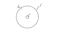
- FIG. 1 is a plan view of the mirror according to the embodiment as viewed from the front surface side.
- FIG. 2 is a plan view of the mirror according to the embodiment as viewed from the back surface side.
- FIG. 3 is a cross-sectional view taken along the line AA shown in FIG.
- FIG. 4 is a cross-sectional view taken along the line BB shown in FIG.
- FIG. 5 is an enlarged cross-sectional view showing the configuration of the outer peripheral rib according to the embodiment.
- FIG. 6 is an enlarged cross-sectional view showing another configuration of the outer peripheral rib according to the embodiment.
- FIG. 7 is an enlarged cross-sectional view showing the configuration of the inner peripheral rib according to the embodiment.
- FIG. 8 is an enlarged cross-sectional view showing the configuration of the bottom surface of the recess according to the embodiment.
- FIG. 9 is an enlarged cross-sectional view showing another configuration of the bottom surface of the recess according to the embodiment.
- FIG. 10 is an enlarged cross-sectional view showing another configuration of the bottom surface of the recess according to the embodiment.
- FIG. 11 is a plan view showing another configuration of the main body according to the embodiment.
- FIG. 12 is a plan view of the mirror according to the first modification of the embodiment as viewed from the front surface side.
- FIG. 13 is a plan view of the mirror according to the first modification of the embodiment as viewed from the back surface side.
- FIG. 14 is a plan view of the split member according to the first modification of the embodiment as viewed from the back surface side.
- FIG. 15 is a cross-sectional view taken along the line CC shown in FIG.
- FIG. 16 is an enlarged cross-sectional view showing another configuration of the connecting rib according to the first modification of the embodiment.
- FIG. 17 is a perspective view showing another configuration of the main body portion according to the first modification of the embodiment.
- FIG. 18 is a plan view showing another configuration of the main body portion according to the first modification of the embodiment.
- FIG. 19 is a plan view of the mirror according to the second modification of the embodiment as viewed from the front surface side.
- FIG. 20 is a plan view of the mirror according to the second modification of the embodiment as viewed from the back surface side.
- FIG. 21 is a cross-sectional view taken along the line DD shown in FIG. 20.
- FIG. 22 is an enlarged cross-sectional view showing the configuration of the inner peripheral rib according to the second modification of the embodiment.
- Astronomical telescopes are equipped with mirrors to reflect the light from the observation target.
- a mirror for example, a mirror for an astronomical telescope having a reflecting surface for reflecting light, a mirror member made of low thermal expansion ceramics, and a reflecting film provided on the reflecting surface of the mirror member is disclosed. Has been done.
- FIG. 1 is a plan view of the mirror 1 according to the embodiment as viewed from the front surface 3 side
- FIG. 2 is a plan view of the mirror 1 according to the embodiment as viewed from the back surface 4 side
- FIG. 3 is a plan view.
- FIG. 2 is a cross-sectional view taken along the line AA shown in FIG.
- the device to which the mirror 1 according to the embodiment is applied is not limited to the astronomical telescope.
- the mirror 1 includes a plate-shaped (disc-shaped in the present disclosure) main body 2 made of ceramic.
- the main body 2 has a front surface 3 and a back surface 4.
- the front surface 3 has a curved surface (for example, a spherical surface) mirror surface 3a on the entire surface.
- the mirror surface 3a is formed, for example, by mirror-processing the entire front surface 3 and then applying a coating that reflects light to the mirror surface.
- the mirror 1 according to the embodiment can reflect light from an observation target on the mirror surface 3a.
- the mirror surface 3a has a concave shape
- the mirror surface 3a is not limited to the concave shape, and may have a planar shape or a convex shape.
- the mirror surface 3a is not limited to a spherical surface, and may be an aspherical surface.
- a cylindrical through hole 5 penetrating from the front surface 3 to the back surface 4 is formed in the central portion of the main body portion 2.
- the light passing through the through hole 5 can be observed by the secondary mirror.
- a plurality of recesses 6 are formed on the back surface 4 of the main body 2.
- the recess 6 has, for example, a fan shape having a central angle of about 60 ° in a plan view. Then, on the back surface 4, six recesses 6 are evenly arranged along the circumferential direction of the disk-shaped main body 2.
- a rib 7 is provided on the back surface 4 of the main body 2 so as to be along the edge of the recess 6. As shown in FIG. 3, the rib 7 is provided so as to rise substantially vertically from the bottom surface 6a of the recess 6 toward the back surface 4.
- the rib 7 includes an outer peripheral rib 7a provided on the outer peripheral side of the back surface 4, an inner peripheral rib 7b provided on the inner peripheral side of the back surface 4, and an outer peripheral rib 7a and an inner peripheral rib 7b. It has a connecting rib 7c provided so as to connect.
- the outer peripheral rib 7a is provided along the outer edge portion of the back surface 4, for example.
- the inner peripheral rib 7b is provided between the through hole 5 and the recess 6 so as to surround the through hole 5, for example.
- the connecting ribs 7c are provided radially, for example, from the central portion of the back surface 4 to the outer edge portion of the back surface 4.
- the volume of the mirror 1 can be reduced by forming a plurality of recesses 6 in the main body 2, so that the weight of the mirror 1 can be reduced. Further, in the embodiment, by forming the rib 7 along the edge of the recess 6, the strength of the mirror 1 reduced in weight by the recess 6 can be ensured.
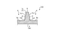
- FIG. 4 is a cross-sectional view taken along the line BB shown in FIG. 2 and is an enlarged cross-sectional view showing the configuration of the connecting rib 7c according to the embodiment.
- the connecting rib 7c has a tapered side surface 7c1.
- the side surface 7c1 is inclined with respect to the back surface 4 so that the inlet side of the recess 6 in contact with the side surface 7c1 is widened.
- the inclination angle ⁇ of the side surface 7c1 is, for example, in the range of 1 ° to 5 °, and the inclination angle ⁇ is preferably in the range of 2 ° to 3 °.
- the connecting rib 7c has the tapered side surface 7c1
- the molded body that is later fired to become the main body 2 is molded with a mold, and then the molded body can be easily molded. Can be demolded from.
- the molded body to be the main body 2 can be easily molded with a mold, so that the mirror 1 can be easily manufactured. Further, in the embodiment, since the tip end side of the connecting rib 7c can be thinned, the weight of the mirror 1 can be reduced.
- the corner portion 7c2 located at the lower end of the connecting rib 7c has an R shape.
- the corner portion 7c2 is a portion where the side surface 7c1 of the connecting rib 7c and the bottom surface 6a of the recess 6 are in contact with each other.
- the corner portion 7c2 of the connecting rib 7c has an R shape, it is possible to suppress the concentration of stress on the corner portion 7c2, so that the strength in the vicinity of the connecting rib 7c in the main body portion 2 can be improved. ..
- both side surfaces 7c1 may be tapered. As a result, after the molded body to be the main body 2 is molded with the mold, the mold can be more easily removed from the molded body.
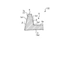
- FIG. 5 is an enlarged cross-sectional view showing the configuration of the outer peripheral rib 7a according to the embodiment.
- the outer peripheral rib 7a according to the embodiment has a tapered side surface 7a1.
- the side surface 7a1 in contact with the recess 6 is inclined with respect to the back surface 4 so that the inlet side of the recess 6 expands.
- the side surface 7a1 which is the outer peripheral side surface of the main body portion 2, is opposed to the back surface 4 so that the back surface 4 side is closer to the center of the main body portion 2 than the front surface 3 side. Is sloping.
- the inclination angle ⁇ of the side surface 7a1 is preferably in the range of 1 ° to 5 °, and the inclination angle ⁇ is preferably in the range of 2 ° to 3 °.
- the outer peripheral rib 7a has the tapered side surface 7a1
- the mold can be easily molded. Can be demolded from.
- the molded body to be the main body 2 can be easily molded with a mold, so that the mirror 1 can be easily manufactured. Further, in the embodiment, since the tip end side of the outer peripheral rib 7a can be thinned, the weight of the mirror 1 can be reduced.
- the corner portion 7a2 located at the lower end of the outer peripheral rib 7a has an R shape.
- the corner portion 7a2 is a portion where the side surface 7a1 of the outer peripheral rib 7a and the bottom surface 6a of the recess 6 are in contact with each other.
- the corner portion 7a2 of the outer peripheral rib 7a has an R shape, it is possible to suppress the concentration of stress on the corner portion 7a2, so that the strength in the vicinity of the outer peripheral rib 7a in the main body portion 2 can be improved. ..
- both side surfaces 7a1 may be tapered, or as shown in FIG. 6, only the side surface 7a1 in contact with the recess 6 may be tapered.
- FIG. 6 is an enlarged cross-sectional view showing another configuration of the outer peripheral rib 7a according to the embodiment.
- the molded body to be the main body 2 can be molded with a mold, and then the mold can be more easily removed from the molded body.
- the mold in contact with the side surface 7a1 is pulled out to the outer peripheral side of the molded body.
- the mold can be pulled out without any particular problem.
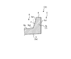
- FIG. 7 is an enlarged cross-sectional view showing the configuration of the inner peripheral rib 7b according to the embodiment.
- the inner peripheral rib 7b according to the embodiment has a tapered side surface 7b1.
- the side surface 7b1 in contact with the recess 6 is inclined with respect to the back surface 4 so that the inlet side of the recess 6 expands.
- the inclination angle ⁇ of the side surface 7b1 is preferably in the range of 1 ° to 5 °, and the inclination angle ⁇ is preferably in the range of 2 ° to 3 °.
- the inner peripheral rib 7b has the tapered side surface 7b1
- the molded body to be later fired to become the main body 2 is molded with a mold, and then the mold is easily molded. Can be demolded from the body.
- the molded body to be the main body 2 can be easily molded with a mold, so that the mirror 1 can be easily manufactured. Further, in the embodiment, since the tip end side of the inner peripheral rib 7b can be thinned, the weight of the mirror 1 can be reduced.
- only the side surface 7b1 in contact with the recess 6 may be tapered. In this way, even when the side surface 7b1 in contact with the through hole 5 is formed substantially perpendicular to the back surface 4, the mold in contact with the side surface 7b1 can be pulled out along the axial direction of the through hole without any particular problem. be able to.
- the corner portion 7b2 located at the lower end of the inner peripheral rib 7b has an R shape.
- the corner portion 7b2 is a portion where the side surface 7b1 of the inner peripheral rib 7b and the bottom surface 6a of the recess 6 are in contact with each other.
- the corner portion 7b2 of the inner peripheral rib 7b has an R shape, it is possible to suppress the concentration of stress on the corner portion 7b2, so that the strength in the vicinity of the inner peripheral rib 7b in the main body portion 2 can be improved. Can be done.
- the width of the outer peripheral rib 7a is wider than the width of the inner peripheral rib 7b and the width of the connecting rib 7c. Thereby, the strength of the mirror 1 can be further improved.
- FIG. 8 is an enlarged cross-sectional view showing the configuration of the bottom surface 6a of the recess 6 according to the embodiment.
- the bottom surface 6a of the recess 6 is preferably a curved surface that follows the shape of the mirror surface 3a.
- the bottom surface 6a of the recess 6 according to the embodiment is not limited to a curved surface that follows the shape of the mirror surface 3a.
- FIG. 9 is an enlarged cross-sectional view showing another configuration of the bottom surface 6a of the recess 6 according to the embodiment.
- the bottom surface 6a of the recess 6 may be stepped along the shape of the mirror surface 3a.
- a mold can be easily formed as compared with the case where the bottom surface 6a includes many curved surfaces, so that the manufacturing cost of the mirror 1 can be reduced. Can be done.
- FIG. 10 is an enlarged cross-sectional view showing another configuration of the bottom surface 6a of the recess 6 according to the embodiment.
- the bottom surface 6a of the recess 6 according to the embodiment may be a flat surface along the shape of the mirror surface 3a.
- the mold can be formed more easily than when the bottom surface 6a includes many curved surfaces, so that the manufacturing cost of the mirror 1 can be reduced. Further, in the example of FIG. 10, since the wall thickness of the mirror surface 3a and the bottom surface 6a can be reduced to the utmost limit, the mirror 1 can be further reduced in weight.
- FIG. 11 is a plan view showing another configuration of the main body 2 according to the embodiment.
- the main body portion 2 may have a flat surface portion 8 on a part of the side surface on the outer peripheral side. In this way, by providing the flat surface portion 8 on a part of the side surface of the main body portion 2, positioning can be facilitated in the process of processing the main body portion 2.
- the dimensional accuracy of the main body 2 can be improved. Further, by providing the flat surface portion 8 on a part of the side surface of the main body portion 2, it is possible to facilitate the positioning when the mirror 1 is installed in the astronomical telescope.
- ceramics constituting the main body 2 for example, cordierite ceramics, aluminum oxide ceramics, zirconium oxide ceramics, silicon nitride ceramics, aluminum nitride ceramics, silicon carbide ceramics, mulite ceramics and the like can be used. it can.
- the main body 2 By forming the main body 2 with ceramics, it is possible to realize a mirror 1 having high mechanical strength and excellent heat resistance.
- the main body 2 by forming the main body 2 with corgerite ceramics having a low specific density and a low coefficient of thermal expansion, the mirror 1 can be made lighter and the reliability in an environment where the temperature changes drastically can be improved. it can.
- the cordierite ceramic of all components 100% by mass constituting the ceramic are those which contain cordierite and (2MgO ⁇ 2Al 2 O 3 ⁇ 5SiO 2) 80 wt%.
- XRD X-ray diffraction
- the material of the main body 2 can be regarded as cordierite ceramics.
- a synthetic cordierite powder obtained by calcining and synthesizing a mixed powder prepared by blending magnesium carbonate powder, aluminum oxide powder and silicon oxide powder in a predetermined ratio is prepared.
- the obtained synthetic cordierite powder and sintering aid powder are weighed in a predetermined ratio and used as the primary raw material.
- the obtained primary raw material powder is wet-mixed, and then a predetermined amount of binder is added to obtain a slurry.
- the obtained slurry is poured into a mold processed into a predetermined shape in advance, dried at a predetermined temperature and time to be solidified, and then molded by a casting molding method or the like of demolding. Further, a molded product is obtained by cutting or the like so as to have an arbitrary shape.
- the obtained molded product is fired in an air atmosphere at a maximum temperature of 1300 ° C. or higher and 1450 ° C. or lower to obtain a fired product.
- the main body 2 according to the embodiment can be obtained by subjecting the fired body to grinding, polishing, coating, etc., if necessary.
- FIG. 12 is a plan view of the mirror 1 according to the modified example 1 of the embodiment as viewed from the front surface 3 side
- FIG. 13 is a plan view of the mirror 1 according to the modified example 1 of the embodiment as viewed from the back surface 4 side. It is a plan view
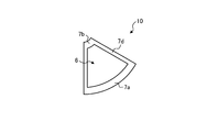
- FIG. 14 is a plan view of the split member 10 according to the modified example 1 of the embodiment as viewed from the back surface 4 side.
- the mirror 1 according to the modified example 1 has the same overall shape as the mirror 1 according to the embodiment, while a plurality of divided members 10 having the same shape are joined to form the main body 2.
- the point of configuration is different from the embodiment.
- the main body 2 of the modified example 1 can be configured by connecting six split members 10 (see FIG. 14) having a fan shape with a central angle of 60 ° in a plan view.
- the mirror 1 can be easily enlarged by connecting a plurality of partitioning members 10 having the same shape to form the main body portion 2. Further, by connecting a plurality of divided members 10 having the same shape to form the main body portion 2, even if a part of the mirror 1 is damaged, only the damaged portion can be replaced.
- a recess 6 is formed in the central portion of the split member 10, and the outer peripheral rib 7a, the inner peripheral rib 7b, and the partial rib 7d (of the connecting rib 7c) are further formed along the edge of the recess 6.
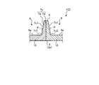
- FIG. 15 is a cross-sectional view taken along the line CC shown in FIG. 13 and is an enlarged cross-sectional view showing the configuration of the connecting rib 7c according to the first modification.
- the connecting rib 7c according to the first modification is configured by connecting the partial ribs 7d of the dividing member 10 together.
- the connecting rib 7c according to the first modification has a tapered side surface 7c1 as in the above-described embodiment. Since the configurations of the outer peripheral ribs 7a and the inner peripheral ribs 7b in the mirror 1 of the modified example 1 are the same as those in the above-described embodiment, the description thereof will be omitted.
- the connecting rib 7c has the tapered side surface 7c1
- the molded body that is later fired to become the dividing member 10 is molded with a mold, and then the mold is easily molded. Can be demolded from the body.
- the molded body to be the dividing member 10 can be easily molded with a mold, so that the mirror 1 can be easily manufactured. Further, in the first modification, the tip side of the connecting rib 7c can be made thinner, so that the mirror 1 can be made lighter.
- a plurality of divided members 10 can be joined by adhering the contact surfaces where the divided members 10 come into contact with each other with a joining material or the like.
- FIG. 16 is an enlarged cross-sectional view showing another configuration of the connecting rib 7c according to the first modification of the embodiment.
- a through hole that penetrates the partial rib 7d of the dividing member 10 in the horizontal direction is formed, the through holes of the adjacent partial ribs 7d are communicated with each other, and the fastening member 20 is inserted into the communicating through hole. Therefore, the adjacent dividing members 10 can be connected to each other.
- the front surfaces 3 of the adjacent divided members 10 are connected to each other. It is possible to prevent the height of the mirror from shifting. Therefore, according to the example of FIG. 16, the surface accuracy of the mirror 1 can be improved.
- the arithmetic average roughness Ra of the contact surfaces where the divided members 10 come into contact with each other is 0.8 ⁇ m or less, and the flatness per unit length is 5 ⁇ m or less.
- the surface accuracy of the mirror surface 3a formed by the set of the front surfaces 3 of each dividing member 10 can be improved.
- FIG. 17 is a perspective view showing another configuration of the main body portion 2 according to the modified example 1 of the embodiment.
- adjacent dividing members 10 may be connected to each other via a plate-shaped member 21 arranged so as to cover the partial rib 7d.
- a plurality of through holes 21a are formed in the plate-shaped member 21, and a screw hole 7d1 is also formed on the surface of the partial rib 7d on the back surface 4 side at a position corresponding to the through hole 21a.
- the plate-shaped members 21 are arranged so as to cover the adjacent partial ribs 7d, and the bolts 22 are screwed into the through holes 21a and the screw holes 7d1, so that the divided members 10 adjacent to each other via the plate-shaped members 21 You can connect them together.
- the front surface 3 of the adjacent divided members 10 It is possible to prevent the heights of each other from shifting. Therefore, according to the example of FIG. 17, the surface accuracy of the mirror 1 can be improved.
- FIG. 17 an example in which a plurality of dividing members 10 are connected by using the plate-shaped member 21 and the fastening member 20 is shown, but only the plate-shaped member 21 is used without using the fastening member 20.
- a plurality of dividing members 10 may be joined together.
- FIG. 18 is a plan view showing another configuration of the main body portion 2 according to the modified example 1 of the embodiment.
- the main body portion 2 of the modified example 1 may have a flat surface portion 8 on a part of the side surface on the outer peripheral side. In this way, by providing the flat surface portion 8 on a part of the side surface of the main body portion 2, positioning can be facilitated in the process of processing the main body portion 2.
- the dimensional accuracy of the main body 2 can be improved. Further, by providing the flat surface portion 8 on a part of the side surface of the main body portion 2, it is possible to facilitate the positioning when the mirror 1 is installed in the astronomical telescope.
- FIG. 19 is a plan view of the mirror 1 according to the modified example 2 of the embodiment as viewed from the front surface 3 side
- FIG. 20 is a plan view of the mirror 1 according to the modified example 2 of the embodiment as viewed from the back surface 4 side. It is a plan view
- FIG. 21 is a cross-sectional view taken along the line DD shown in FIG. 20.
- the mirror 1 according to the modified example 2 is different from the embodiment in that a recess 6A is formed in the central portion of the main body 2 instead of the through hole 5.
- a recess 6A is formed in the central portion of the main body 2 instead of the through hole 5.
- FIG. 22 is an enlarged cross-sectional view showing the configuration of the inner peripheral rib 7b according to the second modification of the embodiment. As shown in FIG. 22, the inner peripheral rib 7b according to the second modification has a tapered side surface 7b1.
- the side surface 7b1 is inclined with respect to the back surface 4 so that the inlet side of the recesses 6 and 6A in contact with each other is widened.
- the inclination angle ⁇ of the side surface 7b1 is preferably in the range of 1 ° to 5 °, and the inclination angle ⁇ is preferably in the range of 2 ° to 3 °.
- the inner peripheral rib 7b has the tapered side surface 7b1
- the molded body to be the main body 2 can be easily molded with a mold, so that the mirror 1 can be easily manufactured. Further, in the second modification, since the tip end side of the inner peripheral rib 7b can be thinned, the weight of the mirror 1 can be reduced.
- the corner portion 7b2 located at the lower end of the inner peripheral rib 7b has an R shape.
- the corner portion 7b2 is a portion where the side surface 7b1 of the inner peripheral rib 7b and the bottom surface 6a of the recess 6 or the bottom surface 6A1 of the recess 6A are in contact with each other.
- the corner portion 7b2 of the inner peripheral rib 7b has an R shape, it is possible to suppress the concentration of stress on the corner portion 7b2, so that the strength in the vicinity of the inner peripheral rib 7b in the main body portion 2 can be improved. Can be done.
- both side surfaces 7b1 are tapered. As a result, after the molded body to be the main body 2 is molded with the mold, the mold can be more easily removed from the molded body.
- the present invention is not limited to the above embodiments, and various modifications can be made without departing from the spirit of the present invention.
- the disk-shaped mirror 1 is shown, but the shape of the mirror 1 is not limited to the disk shape, and can be appropriately changed according to the specifications of various devices to which the mirror 1 is applied. ..
- the main body portion 2 is formed by connecting the six dividing members 10 is shown, but the number of the dividing members 10 constituting the main body portion 2 is not limited to six.
- the mirror 1 has a mirror surface 3a provided on the front surface 3 of the plate-shaped main body 2 made of ceramics and a recess 6 formed on the back surface 4 of the main body 2. And a rib 7 (outer peripheral rib 7a, inner peripheral rib 7b, connecting rib 7c) provided along the edge of the recess 6 and having tapered side surfaces 7a1, 7b1, 7c1. Thereby, the mirror 1 can be easily manufactured.
- the mirror surface 3a is a curved surface
- the bottom surface 6a of the recess 6 is a curved surface along the shape of the mirror surface 3a.
- the mirror surface 3a is a curved surface, and the bottom surface 6a of the recess 6 is stepped along the shape of the mirror surface 3a. Therefore, the manufacturing cost of the mirror 1 can be reduced.
- the mirror surface 3a is a curved surface
- the bottom surface 6a of the recess 6 is a flat surface along the shape of the mirror surface 3a.
- the ribs 7 include an outer peripheral rib 7a provided on the outer peripheral side of the back surface 4, an inner peripheral rib 7b provided on the inner peripheral side of the back surface 4, an outer peripheral rib 7a, and an inner peripheral rib 7b. It has a connecting rib 7c provided so as to connect the two.
- the width of the outer peripheral rib 7a is wider than the width of the inner peripheral rib 7b and the width of the connecting rib 7c. Thereby, the strength of the mirror 1 can be further improved.
- the main body portion 2 has a disk shape and has a flat surface portion 8 on a part of the side surface on the outer peripheral side.
- the main body portion 2 is configured by connecting a plurality of divided members 10 having the same shape. As a result, the size of the mirror 1 can be easily increased, and even if a part of the mirror 1 is damaged, only the damaged portion can be replaced.
- the adjacent dividing members 10 are connected to each other by a fastening member 20 penetrating a part (partial rib 7d) of the rib (connecting rib 7c). Thereby, the surface accuracy of the mirror 1 can be improved.
- the adjacent dividing members 10 are connected to each other via a plate-shaped member 21 arranged so as to cover a part (partial rib 7d) of the rib (connecting rib 7c). Thereby, the surface accuracy of the mirror 1 can be improved.
Landscapes
- Physics & Mathematics (AREA)
- General Physics & Mathematics (AREA)
- Optics & Photonics (AREA)
- Optical Elements Other Than Lenses (AREA)
- Telescopes (AREA)
Priority Applications (4)
| Application Number | Priority Date | Filing Date | Title |
|---|---|---|---|
| JP2021561279A JP7325533B2 (ja) | 2019-11-28 | 2020-11-10 | ミラー |
| US17/780,771 US20230036458A1 (en) | 2019-11-28 | 2020-11-10 | Mirror |
| EP20894783.8A EP4067949B1 (en) | 2019-11-28 | 2020-11-10 | Mirror |
| JP2023125313A JP7518257B2 (ja) | 2019-11-28 | 2023-08-01 | ミラー |
Applications Claiming Priority (2)
| Application Number | Priority Date | Filing Date | Title |
|---|---|---|---|
| JP2019-215322 | 2019-11-28 | ||
| JP2019215322 | 2019-11-28 |
Publications (1)
| Publication Number | Publication Date |
|---|---|
| WO2021106557A1 true WO2021106557A1 (ja) | 2021-06-03 |
Family
ID=76130181
Family Applications (1)
| Application Number | Title | Priority Date | Filing Date |
|---|---|---|---|
| PCT/JP2020/041977 Ceased WO2021106557A1 (ja) | 2019-11-28 | 2020-11-10 | ミラー |
Country Status (4)
| Country | Link |
|---|---|
| US (1) | US20230036458A1 (https=) |
| EP (1) | EP4067949B1 (https=) |
| JP (2) | JP7325533B2 (https=) |
| WO (1) | WO2021106557A1 (https=) |
Citations (5)
| Publication number | Priority date | Publication date | Assignee | Title |
|---|---|---|---|---|
| JPS5412961A (en) * | 1977-06-28 | 1979-01-31 | Bfg Glassgroup | Production of mirror |
| JPH052102U (ja) * | 1991-06-26 | 1993-01-14 | 日本石英硝子株式会社 | 両面使用石英ガラス製軽量ミラー |
| JP2006528126A (ja) * | 2003-07-18 | 2006-12-14 | スネクマ・プロピュルシオン・ソリド | 組成勾配のある熱構造複合材料構造体およびその製造のための方法 |
| JP2007513467A (ja) * | 2003-10-31 | 2007-05-24 | スリーエム イノベイティブ プロパティズ カンパニー | 基板上に微細構造群を形成する方法および同方法に使用される微細構造組立体 |
| JP2009276378A (ja) * | 2008-05-12 | 2009-11-26 | Mitsubishi Electric Corp | 軽量化ミラー及びその製造方法 |
Family Cites Families (15)
| Publication number | Priority date | Publication date | Assignee | Title |
|---|---|---|---|---|
| US5227921A (en) * | 1991-11-27 | 1993-07-13 | Plx Inc. | Light-weighted optical assembly |
| US5565052A (en) * | 1992-03-05 | 1996-10-15 | Industrieanlagen-Betriebsgesellschaft Gmbh | Method for the production of a reflector |
| JP2884555B2 (ja) * | 1993-09-30 | 1999-04-19 | 信越石英株式会社 | 軽量反射鏡 |
| JP3596530B2 (ja) | 2002-02-18 | 2004-12-02 | 三菱マテリアル株式会社 | リブ状物の形成用ブレード |
| US20030234991A1 (en) | 2002-06-20 | 2003-12-25 | Alan Adler | Optical mirror flexing structure and assembly |
| JP2005195706A (ja) * | 2003-12-26 | 2005-07-21 | Hisanori Sako | 分解組み立て可能凹面鏡 |
| JP2009205108A (ja) * | 2008-02-29 | 2009-09-10 | Mitsubishi Electric Corp | 軽量化ミラーおよびその製造方法 |
| JP5294952B2 (ja) * | 2009-04-03 | 2013-09-18 | 三菱電機株式会社 | ミラー構成体 |
| JP5652845B2 (ja) * | 2009-06-01 | 2015-01-14 | Nec東芝スペースシステム株式会社 | 宇宙機搭載用光学装置 |
| DE102011008953B4 (de) * | 2011-01-19 | 2020-08-20 | Schott Ag | Substrat mit Leichtgewichtsstruktur |
| JP5762110B2 (ja) | 2011-04-25 | 2015-08-12 | 三菱電機株式会社 | 軽量化ミラー |
| DE102011051198B4 (de) * | 2011-06-20 | 2016-11-10 | Scanlab Ag | Verfahren zum Herstellen eines gewichtsoptimierten Ablenkspiegels |
| US9958638B2 (en) * | 2013-09-13 | 2018-05-01 | Raytheon Company | Optimal kinematic mount for large mirrors |
| US10145991B2 (en) * | 2016-07-01 | 2018-12-04 | Harris Corporation | Large lightweight mirror for a large telescope and methods for producing the same |
| DE112019005629T5 (de) * | 2018-12-13 | 2021-07-29 | Mitsubishi Electric Corporation | Optische Vorrichtung |
-
2020
- 2020-11-10 WO PCT/JP2020/041977 patent/WO2021106557A1/ja not_active Ceased
- 2020-11-10 US US17/780,771 patent/US20230036458A1/en active Pending
- 2020-11-10 JP JP2021561279A patent/JP7325533B2/ja active Active
- 2020-11-10 EP EP20894783.8A patent/EP4067949B1/en active Active
-
2023
- 2023-08-01 JP JP2023125313A patent/JP7518257B2/ja active Active
Patent Citations (5)
| Publication number | Priority date | Publication date | Assignee | Title |
|---|---|---|---|---|
| JPS5412961A (en) * | 1977-06-28 | 1979-01-31 | Bfg Glassgroup | Production of mirror |
| JPH052102U (ja) * | 1991-06-26 | 1993-01-14 | 日本石英硝子株式会社 | 両面使用石英ガラス製軽量ミラー |
| JP2006528126A (ja) * | 2003-07-18 | 2006-12-14 | スネクマ・プロピュルシオン・ソリド | 組成勾配のある熱構造複合材料構造体およびその製造のための方法 |
| JP2007513467A (ja) * | 2003-10-31 | 2007-05-24 | スリーエム イノベイティブ プロパティズ カンパニー | 基板上に微細構造群を形成する方法および同方法に使用される微細構造組立体 |
| JP2009276378A (ja) * | 2008-05-12 | 2009-11-26 | Mitsubishi Electric Corp | 軽量化ミラー及びその製造方法 |
Non-Patent Citations (1)
| Title |
|---|
| See also references of EP4067949A4 * |
Also Published As
| Publication number | Publication date |
|---|---|
| EP4067949A4 (en) | 2024-01-24 |
| JP7518257B2 (ja) | 2024-07-17 |
| JP2023153922A (ja) | 2023-10-18 |
| JP7325533B2 (ja) | 2023-08-14 |
| EP4067949A1 (en) | 2022-10-05 |
| JPWO2021106557A1 (https=) | 2021-06-03 |
| EP4067949B1 (en) | 2026-01-21 |
| US20230036458A1 (en) | 2023-02-02 |
Similar Documents
| Publication | Publication Date | Title |
|---|---|---|
| JP6898074B2 (ja) | レードーム用ウィスカー強化高破壊靭性セラミックチップ | |
| JP5857088B2 (ja) | 切削工具およびその工具用の丸い両面切削インサート | |
| US6176588B1 (en) | Low cost light weight mirror blank | |
| WO2003106028A1 (ja) | セラミックハニカム構造体及びその製造方法並びにその製造に用いるコート材 | |
| JP7136850B2 (ja) | 被加工ユニット及びその製造方法 | |
| JP6512401B2 (ja) | 反応焼結炭化珪素部材 | |
| EP3067194B1 (en) | Manufacturing method of honeycomb structure, and grinding wheel | |
| JP4460325B2 (ja) | 天体望遠鏡用ミラー | |
| ES2761588T3 (es) | Placa de tuerca de soporte de cerámica de alta resistencia a la fractura y canal de paso | |
| JP5652845B2 (ja) | 宇宙機搭載用光学装置 | |
| WO2021106557A1 (ja) | ミラー | |
| JP2008168634A (ja) | セラミック未焼結体の成形用成形型およびその成形型の使用 | |
| JP6876635B2 (ja) | 焼成用セッター | |
| JP6995030B2 (ja) | ミラー | |
| JP6199696B2 (ja) | 光学部品 | |
| US20170219302A1 (en) | Heat exchanger | |
| JP6679560B2 (ja) | 焼成用セッター | |
| JP2891978B1 (ja) | 炭化珪素質構造体 | |
| JP7604130B2 (ja) | ミラーおよび望遠鏡 | |
| JP6263351B2 (ja) | セラミックス焼結体およびその製造方法 | |
| JP5530275B2 (ja) | 真空吸着装置及びその製造方法 | |
| US20150378128A1 (en) | Method for manufacturing a mirror | |
| JP7145076B2 (ja) | 中間部材 | |
| JP2005234338A (ja) | 位置測定用ミラー | |
| JP6356562B2 (ja) | 流路部材 |
Legal Events
| Date | Code | Title | Description |
|---|---|---|---|
| 121 | Ep: the epo has been informed by wipo that ep was designated in this application |
Ref document number: 20894783 Country of ref document: EP Kind code of ref document: A1 |
|
| ENP | Entry into the national phase |
Ref document number: 2021561279 Country of ref document: JP Kind code of ref document: A |
|
| NENP | Non-entry into the national phase |
Ref country code: DE |
|
| ENP | Entry into the national phase |
Ref document number: 2020894783 Country of ref document: EP Effective date: 20220628 |
|
| WWG | Wipo information: grant in national office |
Ref document number: 2020894783 Country of ref document: EP |