WO2021106495A1 - 打込機 - Google Patents
打込機 Download PDFInfo
- Publication number
- WO2021106495A1 WO2021106495A1 PCT/JP2020/040882 JP2020040882W WO2021106495A1 WO 2021106495 A1 WO2021106495 A1 WO 2021106495A1 JP 2020040882 W JP2020040882 W JP 2020040882W WO 2021106495 A1 WO2021106495 A1 WO 2021106495A1
- Authority
- WO
- WIPO (PCT)
- Prior art keywords
- valve
- passage
- contact portion
- housing
- chamber
- Prior art date
Links
Images


Classifications
-
- B—PERFORMING OPERATIONS; TRANSPORTING
- B25—HAND TOOLS; PORTABLE POWER-DRIVEN TOOLS; MANIPULATORS
- B25C—HAND-HELD NAILING OR STAPLING TOOLS; MANUALLY OPERATED PORTABLE STAPLING TOOLS
- B25C1/00—Hand-held nailing tools; Nail feeding devices
- B25C1/04—Hand-held nailing tools; Nail feeding devices operated by fluid pressure, e.g. by air pressure
- B25C1/044—Hand-held nailing tools; Nail feeding devices operated by fluid pressure, e.g. by air pressure with movable main cylinder
- B25C1/045—Hand-held nailing tools; Nail feeding devices operated by fluid pressure, e.g. by air pressure with movable main cylinder main valve and main cylinder
-
- B—PERFORMING OPERATIONS; TRANSPORTING
- B25—HAND TOOLS; PORTABLE POWER-DRIVEN TOOLS; MANIPULATORS
- B25C—HAND-HELD NAILING OR STAPLING TOOLS; MANUALLY OPERATED PORTABLE STAPLING TOOLS
- B25C1/00—Hand-held nailing tools; Nail feeding devices
- B25C1/04—Hand-held nailing tools; Nail feeding devices operated by fluid pressure, e.g. by air pressure
- B25C1/047—Mechanical details
-
- B—PERFORMING OPERATIONS; TRANSPORTING
- B25—HAND TOOLS; PORTABLE POWER-DRIVEN TOOLS; MANIPULATORS
- B25C—HAND-HELD NAILING OR STAPLING TOOLS; MANUALLY OPERATED PORTABLE STAPLING TOOLS
- B25C1/00—Hand-held nailing tools; Nail feeding devices
- B25C1/04—Hand-held nailing tools; Nail feeding devices operated by fluid pressure, e.g. by air pressure
- B25C1/044—Hand-held nailing tools; Nail feeding devices operated by fluid pressure, e.g. by air pressure with movable main cylinder
- B25C1/046—Trigger valve and trigger mechanism
Definitions
- the present invention relates to a driving machine provided with a striking portion that operates on the pressure of a gas.
- Patent Document 1 describes an example of a driving machine provided with a striking portion that operates by the pressure of gas.
- the driving machine described in Patent Document 1 includes a housing, a driver as a striking part, a first pressure chamber, a valve seat, a passage provided in the valve seat, an exhaust valve as a valve body, an exhaust valve chamber, a pressure accumulator chamber, and a cylinder. It has a head cap, a valve, an injection part, a trigger, a push lever and a magazine.
- the driver can act on the housing.
- the cylinder is operable within the housing.
- the first pressure chamber is provided in the housing and operates the driver by the pressure of air as a gas.
- the head cap and valve seat are fixedly provided in the housing.
- the exhaust valve is operably provided in the housing.
- the exhaust valve chamber is provided in the housing. Compressed air is supplied to the accumulator chamber.
- the injection section is attached to the housing.
- the magazine is attached to the ejection section, and the stopper in
- the valve connects the accumulator chamber and the exhaust valve chamber and shuts off the exhaust valve chamber and the outside of the housing. Then, the air in the accumulator chamber is supplied to the exhaust valve chamber, and the exhaust valve operates and is pressed against the valve seat. That is, the exhaust valve closes the passage. Therefore, the cylinder operates by the air pressure of the accumulator chamber, and the cylinder is separated from the head cap. As a result, the air in the accumulator chamber is supplied to the first pressure chamber, the driver operates from the top dead center to the bottom dead center, and the driver hits the stopper.
- the inventor of the present application has recognized the problem that when the valve body repeatedly touches and separates from the valve seat, the strength of the valve body decreases and the function of the valve body to close the passage decreases.
- An object of the present invention is to provide a driving machine capable of suppressing a decrease in the strength of the valve body when the operation of contacting and separating the valve body from the valve seat is repeated.
- the driving machine of one embodiment includes an operable striking portion, a first pressure chamber for operating the striking portion with a gas pressure, a housing provided with the striking portion and the first pressure chamber, and the housing.
- a valve seat fixed inside, a passage provided in the valve seat and connecting the first pressure chamber and the outside of the housing, and an operably provided inside the housing, and said A driving machine having a valve body that opens and closes the passage by being contacted and separated from the valve seat, wherein the valve body is a contact portion and a non-contact portion arranged outside the first pressure chamber.
- a contact portion is provided, and the contact portion is brought into contact with and separated from the valve seat outside the passage in the radial direction of the passage in a first direction intersecting with the operating direction of the valve body to provide the passage.
- the non-contact portion is opened and closed, and the non-contact portion is provided inside the contact portion in the radial direction of the passage in the first direction, and the non-contact portion is the contact in the second direction which is the operating direction of the valve body.
- the portion is provided at a position separated from the valve seat in the operating direction of the valve body in a state where the portion is in contact with the valve seat.
- the valve body can maintain the function of closing the passage.
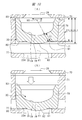
- (A) and (B) are cross-sectional views showing a specific example of an exhaust valve. It is a bottom view of the exhaust valve shown in FIGS.
- A) and (B) are cross-sectional views showing still another specific example of the exhaust valve.
- the driving machine 10 shown in FIG. 1 includes a housing 11, an injection unit 12, a striking unit 13, a trigger 14, a push lever 15, a trigger valve 16, and a push lever valve 17.
- the housing 11 has a body 18, a handle 19, and a head cover 20.
- the body portion 18 has a tubular shape, and the handle 19 is connected to the body portion 18.
- the head cover 20 is fixed to the first end portion in the longitudinal direction of the body portion 18, and the head cover 20 closes the opening of the body portion 18.
- the injection portion 12 is fixed to the second end portion in the longitudinal direction of the body portion 18.
- a plug 21 is provided on the handle 19 and an air hose is connected to the plug 21.
- a cylinder 22 is provided in the body portion 18.
- the cylinder 22 can move in the direction along the center line A1 with respect to the housing 11.
- the center line A1 is the center line of the cylinder 22.
- the striking portion 13 is arranged inside and outside the cylinder 22. The striking portion 13 can operate in the direction along the center line A1 with respect to the cylinder 22.
- the pressure accumulator chamber 23 is provided in the handle 19, the body portion 18, and the head cover 20. The compressed air supplied from the air hose is stored in the accumulator chamber 23.
- the base 70, the head cap 27 and the valve seat 31 are arranged in the head cover 20.
- the base 70 is fixed to the head cover 20
- the head cap 27 is fixed to the base 70
- the valve seat 31 is fixed to the head cap 27.
- the head cap 27 is made of metal, for example, steel or an aluminum alloy.
- An exhaust passage 28 is provided over the head cover 20, the base 70, and the head cap 27. The exhaust passage 28 is connected to the outer B1 of the housing 11.
- the base 70 has an exhaust valve chamber 26, and the exhaust valve chamber 26 is connected to a passage 25.
- the head cap 27 has a guide hole 71, and the exhaust valve 30 is arranged in the guide hole 71.
- the exhaust valve 30 can move in the direction along the center line A1 with respect to the head cap 27.
- the valve seat 31 is made of synthetic rubber, and the valve seat 31 has a piston upper chamber 32 and a passage 29.
- the passage 29 is a hole through which compressed air can pass.
- the piston upper chamber 32 is connected to the passage 29.
- the exhaust valve 30 is arranged outside the passage 29 and the piston upper chamber 32.
- the striking portion 13 has a piston 33 and a driver blade 34.
- the piston 33 and the driver blade 34 may be integrally molded products.
- the piston 33 and the driver blade 34 may be fixed with separate parts.
- the piston 33 is provided in the cylinder 22, and the piston 33 can operate in the direction along the center line A1 with respect to the cylinder 22.
- the piston 33 is urged by the pressure of the piston upper chamber 32 in a direction away from the valve seat 31 in the direction along the center line A1.
- a seal member 97 is attached to the outer peripheral surface of the piston 33. The seal member 97 comes into contact with the inner peripheral surface of the cylinder 22.
- a piston lower chamber 35 is provided between the piston 33 and the injection portion 12 in the direction along the center line A1 in the cylinder 22.
- the seal member 97 separates the piston upper chamber 32 and the piston lower chamber 35.
- a return air chamber 36 is provided between the body portion 18 and the cylinder 22. Passages 37 and 38 that penetrate the cylinder 22 in the radial direction are provided.
- a check valve 98 is attached to the outer periphery of the cylinder 22. The check valve 98 operates by the pressure in the cylinder 22 and opens and closes the passage 37.
- the passage 38 shown in FIG. 3 always connects the piston lower chamber 35 and the return air chamber 36.
- the passage 38 is arranged between the passage 37 and the injection portion 12 in the direction along the center line A1.
- the bumper 39 shown in FIG. 3 is provided in the body portion 18. A part of the bumper 39 is arranged in the cylinder 22 and is in contact with the injection portion 12.
- the bumper 39 is made of synthetic rubber.
- the bumper 39 has a shaft hole 40.
- a spring 41 as an urging member is provided in the body portion 18.
- the spring 41 urges the cylinder 22 in a direction along the center line A1 so as to approach the valve seat 31.
- a passage 42 is formed between the end of the cylinder 22 and the valve seat 31.
- the injection portion 12 is fixed to the body portion 18.
- the injection unit 12 has an injection path 43.
- the injection path 43 is connected to the shaft hole 40.
- the driver blade 34 can operate in the shaft hole 40 and the injection path 43 in the direction along the center line A1.
- the holder 44 is provided inside the body portion 18.
- the holder 44 is annular, and the holder 44 is arranged outside the cylinder 22 in the radial direction of the cylinder 22.
- the holder 44 has a passage 45, and the passage 45 is connected to the accumulator chamber 23.
- Flange 46, 47 is provided on the outer peripheral surface of the cylinder 22.
- a control chamber 49 is provided between the flange 46 and the flange 47. The control chamber 49 is connected to the accumulator chamber 23 by a passage 45.
- a partition wall 99 is provided to separate the inside of the head cover 20 and the inside of the body portion 18.
- a control chamber 50 is formed between the partition wall 99 and the flange 46.
- the body portion 18 has a passage 51, and the control chamber 50 is connected to the passage 51.
- the passage 51 is connected to the passage 25.
- the flange 46 receives the pressure of the control chambers 49 and 50, and the flange 47 receives the pressure of the control chamber 49.
- the cylinder 22 is urged in the direction along the center line A1 by the pressure of the control chambers 49 and 50 and the urging force of the spring 41.
- the trigger 14 is attached to the housing 11 as shown in FIG.
- the trigger 14 can be operated within a range of a predetermined angle about the support shaft 52.
- a spring is attached to the support shaft 52, and the spring urges the trigger 14 clockwise around the support shaft 52.
- the trigger 14 can operate counterclockwise against the urging force of the spring.
- the trigger 14 operates clockwise by the urging force of the spring.
- the push lever 15 is attached to the injection portion 12 as shown in FIG.
- the push lever 15 can operate in the direction along the center line A1 with respect to the housing 11 and the injection portion 12.
- the push lever 15 is urged by a spring in a direction away from the housing 11.
- the push lever 15 urged by the spring comes into contact with the stopper 55 and stops at the initial position.
- the push lever 15 can operate in a direction approaching the housing 11 against the urging force of the spring.
- the structure of the trigger valve 16 and the push lever valve 17 is shown in FIG.
- the trigger valve 16 has a tubular guide portion 56, a ball-shaped valve member 57, a plunger 58, and a passage 59.
- the guide portion 56 is attached to the housing 11.
- the plunger 58 can be actuated with respect to the guide portion 56.
- the trigger 14 is separated from the plunger 58, and the trigger valve 16 is in the initial state.
- the trigger valve 16 in the initial state shuts off the accumulator chamber 23 and the passage 59, and connects the passage 59 and the external B1.
- the trigger valve 16 switches from the initial state to the operating state.
- the trigger valve 16 in the operating state connects the accumulator chamber 23 and the passage 59, and shuts off the passage 59 and the external B1. Therefore, the compressed air in the accumulator chamber 23 flows into the passage 59.
- the push lever valve 17 has a pressure chamber 60, a valve body 61, a plunger 62, a valve member 63, and a spring.
- the pressure chamber 60 is connected to the passage 59.
- the valve body 61 is attached to the housing 11, and the plunger 62 and the valve member 63 can operate with respect to the valve body 61, respectively.
- the valve body 61 has an exhaust passage 65. The spring urges the valve member 63 in a direction closer to the plunger 62.
- a transmission member 66 is provided, and the transmission member 66 can operate with respect to the valve body 61.
- the transmission member 66 has a tubular shape, and a part of the valve body 61 is arranged in the transmission member 66.
- a spring 67 is provided in the transmission member 66. The spring 67 urges the plunger 62 in a direction away from the valve member 63.
- the push lever 15 has an arm 68, and the arm 68 and the transmission member 66 are connected so as to be able to transmit power.
- the push lever 15 When the push lever 15 is separated from the object W1, the push lever 15 is stopped at the initial position. The operating force is not transmitted from the push lever 15 to the transmission member 66, and the transmission member 66 is stopped at the initial position. Further, the push lever valve 17 is in the initial state shown in FIG. When the push lever valve 17 is in the initial state, the plunger 62 is stopped at the initial position and the exhaust passage 65 is opened. Further, the valve member 63 shuts off the pressure chamber 60 and the passage 51.
- the push lever valve 17 switches from the initial state to the operating state shown in FIG.
- the plunger 62 shuts off the exhaust passage 65, and the valve member 63 operates against the urging force of the spring by the operating force of the plunger 62, so that the pressure chamber 60 and the passage 51 And connect.
- the magazine 85 shown in FIGS. 1 and 3 is attached to the driving machine 10.
- the magazine 85 houses the nail 86.
- the magazine 85 is supported by an injection section 12 and a handle 19.
- the feeder 87 is provided in the magazine 85, and the feeder 87 sends the nail 86 to the injection path 43.
- the trigger valve 16 When the operator releases the operating force on the trigger 14 and separates the push lever 15 from the object W1 as shown in FIG. 3, the trigger valve 16 is in the initial state and the push lever valve 17 is in the initial state. Is in the initial state. That is, the trigger valve 16 shuts off the accumulator chamber 23 and the passage 59. Further, in the push lever valve 17, the push lever valve 17 shuts off the pressure chamber 60 and the passage 51, and connects the passage 51 and the exhaust passage 65.
- the exhaust valve chamber 26 is connected to the outer B1 of the housing 11 via the passages 25 and 51 and the exhaust passage 65. Therefore, the exhaust valve 30 is stopped at the initial position in contact with the holder as shown in FIG. When the exhaust valve 30 is stopped at the initial position, the exhaust valve 30 is separated from the end surface 77 of the head cap 27. That is, the exhaust valve 30 opens the passage 29, and the piston upper chamber 32 and the outside of the housing 11 are connected to each other. Therefore, the piston upper chamber 32 is connected to the external B1 via the exhaust passage 28.
- the pressure of the piston upper chamber 32 is substantially the same as the atmospheric pressure.
- control room 50 is connected to the outer B1 of the housing 11 via the passage 51 and the exhaust passage 65. Therefore, the cylinder 22 is pressed against the valve seat 31 by the pressure of the control chamber 49 and the urging force of the spring 41, and the passage 42 is closed. Therefore, the compressed air in the accumulator chamber 23 is not supplied to the piston upper chamber 32, and the striking portion 13 is stopped at the top dead center. When the striking portion 13 is stopped at top dead center, the piston 33 is in contact with the valve seat 31.
- the piston lower chamber 35 is connected to the outside B1 via the shaft hole 40, and the pressure of the piston lower chamber 35 is substantially atmospheric pressure.
- the trigger 14 When the operator applies an operating force to the trigger 14, the trigger 14 operates counterclockwise in FIG. 3, and the trigger 14 stops at the operating position shown in FIG. Then, the trigger valve 16 switches from the initial state to the operating state. Further, when the operator brings the push lever 15 into contact with the object W1 and the push lever 15 operates in a direction approaching the housing 11, the push lever valve 17 switches from the initial state to the operating state.
- the striking portion 13 operates from the top dead center to the bottom dead center as shown in FIG. 6, that is, descends.
- the driver blade 34 strikes the nail 86 in the injection path 43, and the nail 86 is driven into the object W1.
- the check valve 98 operates by the pressure of the compressed air flowing into the cylinder 22 to open the passage 37. Therefore, a part of the compressed air in the cylinder 22 flows into the return air chamber 36 through the passage 37.
- the bumper 39 absorbs a part of the kinetic energy of the striking portion 13. Further, the striking portion 13 stops at the bottom dead center.
- the piston 33 is pressed against the bumper 39, and the piston 33 shuts off the piston lower chamber 35 and the shaft hole 40.
- the push lever 15 is separated from the object W1 as shown in FIG. 9 by the reaction of the striking portion 13 driving the nail 86 into the object W1. Then, the push lever 15 operates by the urging force of the spring and stops at the initial position. Therefore, the push lever valve 17 switches from the operating state to the initial state. Further, the operator releases the operating force on the trigger 14. Therefore, the trigger valve 16 switches from the operating state to the initial state.
- the exhaust valve 30 operates by the pressure of the piston upper chamber 32 and is separated from the end face 77, and the passage 29 and the exhaust passage are separated from each other. Connect with 28.
- the exhaust valve 30 comes into contact with the base 70 as shown in FIG. 8 and stops at the initial position. Therefore, the compressed air in the piston upper chamber 32 is discharged to the outside B1 through the exhaust passage 28.
- the pressure in the piston upper chamber 32 becomes approximately atmospheric pressure.
- the compressed air in the control chamber 50 and the compressed air in the exhaust valve chamber 26 are discharged to the outside B1 through the passage 51 and the exhaust passage 65 as shown in FIGS. 8 and 9. Therefore, the cylinder 22 operates in a direction approaching the valve seat 31 as shown in FIG. 8, closes the passage 42, and stops. Further, the piston 33 receives the pressure of the compressed air flowing from the return air chamber 36 through the passage 38 into the piston lower chamber 35, and the striking portion 13 is directed from the bottom dead center to the top dead center as shown in FIG. To operate. Then, when the piston 33 comes into contact with the valve seat 31 as shown in FIG. 1, the striking portion 13 stops at the top dead center. After the striking portion 13 stops at the top dead center, the air in the piston lower chamber 35 is discharged to the outside B1 through the shaft hole 40, and the pressure in the piston lower chamber 35 becomes substantially atmospheric pressure.
- the exhaust valve 30 is made of synthetic resin or synthetic rubber.
- synthetic resin for example, a thermoplastic resin, specifically a urethane resin can be used. Urethane rubber can be used as the synthetic rubber.
- the exhaust valve 30 has a wall portion 78 and a tubular portion 79 connected to the wall portion 78.
- the exhaust valve 30 has a circular outer surface shape in a second plane intersecting the center line A1, for example, in a plane perpendicular to the center line A1, as shown in FIG.
- the shape of the passage 29 and the opening 29A is circular.
- the inner diameter of the guide hole 71 is larger than the inner diameter of the opening 29A of the passage 29.
- the outer diameter of the exhaust valve 30 is larger than the outer diameter of the guide hole 71.
- the outer peripheral surface of the exhaust valve 30 is pressed against the head cap 27 and is elastically deformed.
- the exhaust valve 30 can operate in the guide hole 71 in the direction along the center line A1.
- the exhaust valve 30 is arranged between the base 70 and the end face 77.
- the end 83 of the exhaust valve 30 in the direction along the center line A1 can contact the base 70.
- the exhaust valve 30 has a contact portion 80, a non-contact portion 81, and a bulge portion 82.
- the contact portion 80, the non-contact portion 81, and the bulge portion 82 are located opposite to the end portion 83 in the direction along the center line A1.
- the bulge 82 is provided on the wall 78.
- the contact portion 80 and the non-contact portion 81 are arranged in an annular shape with the center line A1 as the center.
- the non-contact portion 81 is inside the contact portion 80. It is located and is located outside the bulge 82.
- the contact portion 80 and the non-contact portion 81 are arranged concentrically. As shown in FIG. 11, the contact portion 80 is arranged outside the opening 29A of the passage 29 in the second plane intersecting the center line A1. The non-contact portion 81 and the bulging portion 82 are arranged in the second plane intersecting with the center line A1, and the opening 29A of the passage 29 is also arranged inside.
- the non-contact portion 81 is a recess or a recess arranged between the contact portion and the bulge portion 82.
- the bulging portion 82 projects from the non-contact portion 81 toward the passage 29 in the first plane along the center line A1.
- the exhaust valve 30 airtightly separates the exhaust valve chamber 26 from the exhaust passage 28 regardless of the position in the direction along the center line A1. Further, the exhaust valve 30 can be brought into contact with and separated from the end face 77. It has a function of connecting and blocking the passage 29 and the exhaust passage 28. As shown in FIG. 10A, when the contact portion 80 of the exhaust valve 30 is separated from the end surface 77, the passage 29 and the exhaust passage 28 are connected.
- the exhaust valve 30 When the pressure in the exhaust valve chamber 26 rises, the exhaust valve 30 operates so as to approach the end face 77 due to the pressure in the direction along the center line A1. Then, as shown in FIGS. 10B and 12A, the contact portion 80 of the exhaust valve 30 comes into contact with the end face 77. Further, when the contact portion 80 is elastically deformed, as shown in FIG. 12B, the contact portion 80 is in close contact with the end surface 77, and the passage 29 and the exhaust passage 28 are blocked.
- the exhaust valve 30 can suppress the function of shutting off the passage 29 and the exhaust passage 28, that is, the deterioration of the sealing property.
- a low-strength material can be used as the material of the exhaust valve 30, and the manufacturing cost of the exhaust valve 30 can be reduced as compared with the case where a high-strength material is used as the material of the exhaust valve 30.
- the opening 29A is chamfered with the corners removed in the second plane along the center line A1.
- the chamfer shape may be, for example, a chamfer curved in an arc shape or a straight chamfer.
- the chamfer curved in an arc shape is called "R chamfer”.
- the linear chamfer is called "C chamfer”. Therefore, it is possible to more reliably avoid the concentration of stress at the portion of the exhaust valve 30 corresponding to the edge of the head cap 27.
- a part of the inner surface 84 of the wall portion 78 and the surface of the bulging portion 82 are spherical surfaces centered on the point B2.
- the point B2 is located on the center line A1.
- the thickness T1 of the wall portion 78 is constant at any position in the circumferential direction of the virtual circle centered on the point B2. Therefore, the exhaust valve 30 that receives the pressure of the exhaust valve chamber 26 has a uniform amount of elastic deformation, and the concentration of stress in the exhaust valve 30 can be more reliably avoided.
- the exhaust valve 30 has a contact portion 88 and a non-contact portion 100.
- the contact portions 88 are arranged in an annular shape with the center line A1 as the center.
- the non-contact portion 100 is arranged inside the contact portion 88 in the second plane intersecting the center line A1.
- the outer peripheral shape of the non-contact portion 100 is a circle centered on the center line A1.
- the contact portion 88 and the non-contact portion 100 are arranged concentrically.
- the non-contact portion 100 is a flat surface perpendicular to the center line A1.
- the length L4 from the end portion 83 to the tip of the contact portion 88 is larger than the length L5 from the end portion 83 to the non-contact portion 100. That is, the non-contact portion 100 can be defined as a recess or a recess arranged inside the contact portion 88 in the radial direction centered on the center line A1.
- a tapered surface 89 is provided on the outside of the contact portion 88, and a tapered surface 90 is provided on the outside of the tapered surface 89.
- Both the tapered surface 89 and the tapered surface 90 are arranged in an annular shape with the center line A1 as the center.
- the tapered surface 89 and the tapered surface 90 are inclined with respect to the center line A1.
- the tapered surface 90 is arranged outside the tapered surface 89 in the radial direction centered on the center line A1, that is, in the direction D1.
- the tapered surface 89 and the tapered surface 90 are connected by an end surface 91.
- the exhaust valve 30 shown in FIG. 13A has a function of connecting and shutting off the passage 29 and the exhaust passage 28. As shown in FIG. 13A, when the contact portion 88 of the exhaust valve 30 is separated from the end surface 77, the passage 29 and the exhaust passage 28 are connected.
- the exhaust valve 30 When the pressure in the exhaust valve chamber 26 rises, the exhaust valve 30 operates so as to approach the end face 77 due to the pressure in the direction along the center line A1. Then, as shown in FIG. 13B, the contact portion 88 of the exhaust valve 30 comes into contact with the end surface 77. Further, when the contact portion 88 is elastically deformed, the contact portion 88 is brought into close contact with the end surface 77, and the passage 29 and the exhaust passage 28 are blocked from each other.
- the non-contact portion 100 is a part of the surface of the wall portion 78.
- the wall portion 78 has a constant thickness T2 in the direction along the center line A1. Therefore, the exhaust valve 30 that receives the pressure of the exhaust valve chamber 26 has a uniform amount of elastic deformation, and the concentration of stress in the exhaust valve 30 can be more reliably avoided.
- the exhaust valve 30 has a tapered surface 90 that connects to the contact portion 88.
- the exhaust valve 30 shown in FIG. 15 (A) does not have the tapered surface 89 and the end surface 91 shown in FIG. FIG. 15 (A) shows a state in which the contact portion 88 is separated from the end face 77, and FIG. 15 (B) shows a state in which the contact portion 88 is in contact with the end face 77.
- the exhaust valve 30 shown in FIGS. 15 (A) and 15 (B) can obtain the same effect as the exhaust valve 30 shown in FIGS. 13 (A) and 13 (B).
- the driving machine 10 is an example of a driving machine.
- the striking portion 13 is an example of the striking portion.
- the piston upper chamber 32 is an example of the first pressure chamber.
- the housing 11 is an example of a housing.
- the head cap 27 is an example of a valve seat.
- the exhaust valve 30 is an example of a valve body.
- the passage 29 is an example of a passage.
- the direction along the center line A1 is an example of the second direction.
- the direction that intersects the center line A1, that is, the direction D1 that intersects the center line A1 at approximately 90 degrees is the first direction.
- 11 and 14 are examples of "a first plane including a first direction intersecting with a second direction which is the operating direction of the valve body", respectively.
- 10 (A), 10 (B), 13 (A), 13 (B), 15 (A), and 15 (B) are "second directions along the operating direction of the valve body," respectively. This is an example of a "second plane” including.
- the opening 29A is an example of an opening.
- the contact portions 80 and 88 are examples of the contact portions, respectively.
- the non-contact portions 81 and 100 are examples of non-contact portions, respectively.
- the bulge 82 is an example of a bulge.
- the opening 29A is an example of a curved portion.
- the accumulator chamber 23 is an example of the accumulator chamber.
- the exhaust valve chamber 26 is an example of a second pressure chamber.
- the trigger valve 16 and the push lever valve 17 are examples of valves.
- the trigger 14 is an example of a trigger.
- the push lever 15 is an example of a push lever.
- the injection unit 12 is an example of an injection unit.
- the magazine 85 is an example of a magazine.
- the nail 86 is an example of a stopper.
- the driving machine is not limited to the disclosed embodiment, and can be variously changed without departing from the gist thereof.
- the compressible gas supplied to the accumulator chamber may be an inert gas, for example, nitrogen gas or a noble gas, instead of air.
- Triggers include levers, buttons, arms, and the like.
- the operation of the operating member may be either a rotational operation within a predetermined angle range or a linear reciprocating operation.
- the push lever may have either a shaft shape or a hollow shape.
- the housing may be an element called a casing or body.
- the first pressure chamber and the second pressure chamber are spaces to which compressed air is supplied and discharged, respectively.
- the passage includes holes, gaps, and grooves through which gas can pass.
Landscapes
- Physics & Mathematics (AREA)
- Fluid Mechanics (AREA)
- Engineering & Computer Science (AREA)
- Mechanical Engineering (AREA)
- Portable Nailing Machines And Staplers (AREA)
Abstract
弁座に接触及び離間される弁体の強度が低下することを抑制可能な打込機を提供する。作動可能な打撃部(13)と、気体の圧力で打撃部(13)を作動させるピストン上室(32)と、ハウジング(11)と、ハウジング(11)内に設けられたヘッドキャップ(27)と、ヘッドキャップ(27)に設けられた通路(29)と、ハウジング(11)内に作動可能に設けられ、かつ、通路(29)を開閉するエキゾーストバルブ(30)と、を有する、打込機(10)であって、エキゾーストバルブ(30)は、接触部(80)及び非接触部(81)を備え、接触部(80)は、通路(29)の径方向で通路(29)よりも外側でヘッドキャップ(27)に接触及び離間され、非接触部(81)は、通路(29)の径方向で接触部(80)よりも内側に設けられ、非接触部(81)は、接触部(80)がヘッドキャップ(27)に接触された状態で、ヘッドキャップ(27)から離間する位置に設けられている。
Description
本発明は、気体の圧力で作動する打撃部を備えた打込機に関する。
気体の圧力で作動する打撃部を備えた打込機の一例が、特許文献1に記載されている。特許文献1に記載された打込機は、ハウジング、打撃部としてのドライバ、第1圧力室、弁座、弁座に設けた通路、弁体としてのエキゾーストバルブ、エキゾーストバルブ室、蓄圧室、シリンダ、ヘッドキャップ、バルブ、射出部、トリガ、プッシュレバー及びマガジンを有する。ドライバは、ハウジングに対して作動可能である。シリンダは、ハウジング内で作動可能である。第1圧力室は、ハウジング内に設けられ、かつ、気体としての空気の圧力でドライバを作動させる。ヘッドキャップ及び弁座は、ハウジング内に固定して設けられている。エキゾーストバルブは、ハウジング内に作動可能に設けられている。エキゾーストバルブ室は、ハウジング内に設けられている。蓄圧室には圧縮空気が供給される。射出部は、ハウジングに取り付けられている。マガジンは射出部に取り付けられ、マガジン内の止具は、射出部へ送られる。
特許文献1に記載された打込機は、ユーザがトリガ及びプッシュレバーを停止させていると、バルブが蓄圧室とエキゾーストバルブ室とを遮断し、かつ、エキゾーストバルブ室とハウジングの外部とを接続する。このため、エキゾーストバルブは、弁座から離間されて通路を開いている。また、シリンダは、ヘッドキャップに接触して停止している。したがって、蓄圧室から第1圧力室に空気は供給されず、ドライバは、上死点で停止している。
これに対して、ユーザがトリガ及びプッシュレバーを作動させると、バルブが蓄圧室とエキゾーストバルブ室とを接続し、かつ、エキゾーストバルブ室とハウジングの外部とを遮断する。すると、蓄圧室の空気がエキゾーストバルブ室に供給され、エキゾーストバルブが作動して弁座へ押し付けられる。つまり、エキゾーストバルブは、通路を閉じる。このため、シリンダは、蓄圧室の空気圧で作動し、シリンダがヘッドキャップから離間する。その結果、蓄圧室の空気が第1圧力室に供給され、ドライバは、上死点から下死点に向けて作動し、ドライバが止具を打撃する。
本願発明者は、弁体が弁座に接触及び離間される動作が繰り返されると、弁体の強度が低下し、弁体が通路を閉じる機能が低下する、という課題を認識した。
本発明の目的は、弁体が弁座に接触及び離間される動作が繰り返された場合に、弁体の強度が低下することを抑制可能な打込機を提供することである。
一実施形態の打込機は、作動可能な打撃部と、気体の圧力で前記打撃部を作動させる第1圧力室と、前記打撃部及び前記第1圧力室が設けられたハウジングと、前記ハウジング内に固定して設けられた弁座と、前記弁座に設けられ、かつ、前記第1圧力室と前記ハウジングの外部とをつなぐ通路と、前記ハウジング内に作動可能に設けられ、かつ、前記弁座に接触及び離間されることにより、前記通路を開閉する弁体と、を有する、打込機であって、前記弁体は、前記第1圧力室の外に配置された接触部及び非接触部を備え、前記接触部は、前記弁体の作動方向に対して交差する第1方向における前記通路の径方向において、前記通路よりも外側で前記弁座に接触及び離間されて前記通路を開閉し、前記非接触部は、前記第1方向における前記通路の径方向において前記接触部よりも内側に設けられ、前記非接触部は、前記弁体の作動方向である第2方向において前記接触部が前記弁座に接触された状態で、前記弁体の作動方向で前記弁座から離間する位置に設けられている。
一実施形態の打込機によれば、弁体が弁座に接触及び離間される動作が繰り返された場合に、弁体の強度が低下することを抑制可能である。したがって、弁体が通路を閉じる機能を維持できる。
次に、本発明の打込機に含まれるいくつかの実施形態のうち、代表的な打込機を図面を参照して説明する。
図1に示す打込機10は、ハウジング11、射出部12、打撃部13、トリガ14、プッシュレバー15、トリガバルブ16及びプッシュレバーバルブ17を有する。ハウジング11は、胴部18、ハンドル19及びヘッドカバー20を有する。胴部18は筒形状あり、ハンドル19は胴部18に接続されている。ヘッドカバー20は、胴部18の長手方向で第1端部に固定されており、ヘッドカバー20は、胴部18の開口部を塞いでいる。また、射出部12は、胴部18の長手方向で第2端部に固定されている。プラグ21がハンドル19に設けられ、プラグ21にエアホースが接続される。
胴部18内にシリンダ22が設けられている。シリンダ22は、ハウジング11に対して中心線A1に沿った方向に移動可能である。中心線A1は、シリンダ22の中心線である。打撃部13は、シリンダ22の内部及び外部に亘って配置されている。打撃部13は、シリンダ22に対して中心線A1に沿った方向に作動可能である。蓄圧室23が、ハンドル19内、胴部18内、ヘッドカバー20内に亘って設けられている。エアホースから供給される圧縮空気は、蓄圧室23に溜められる。
基部70、ヘッドキャップ27及びバルブシート31が、ヘッドカバー20内に配置されている。基部70はヘッドカバーに20に固定され、ヘッドキャップ27は基部70に固定され、バルブシート31はヘッドキャップ27に固定されている。ヘッドキャップ27は、金属製、例えば、鋼製、アルミニウム合金製である。排気通路28が、ヘッドカバー20、基部70及びヘッドキャップ27に亘って設けられている。排気通路28は、ハウジング11の外部B1につながっている。
基部70は、エキゾーストバルブ室26を有し、エキゾーストバルブ室26は、通路25につながっている。ヘッドキャップ27は、ガイド孔71を有し、エキゾーストバルブ30がガイド孔71に配置されている。エキゾーストバルブ30は、ヘッドキャップ27に対して中心線A1に沿った方向に移動可能である。バルブシート31は、合成ゴム製であり、バルブシート31はピストン上室32及び通路29を有する。通路29は、圧縮空気が通過可能な孔である。ピストン上室32は、通路29につながっている。エキゾーストバルブ30は、通路29及びピストン上室32の外に配置されている。
打撃部13は、ピストン33及びドライバブレード34を有する。ピストン33及びドライバブレード34は、一体成型品でもよい。ピストン33とドライバブレード34とは、別部品を固定したものでもよい。ピストン33はシリンダ22内に設けられ、ピストン33は、シリンダ22に対して中心線A1に沿った方向に作動可能である。ピストン33は、ピストン上室32の圧力により、中心線A1に沿った方向でバルブシート31から離間する向きで付勢される。ピストン33の外周面にシール部材97が取り付けられている。シール部材97は、シリンダ22の内周面に接触する。
図1のように、シリンダ22内における中心線A1に沿った方向で、ピストン33と射出部12との間に、ピストン下室35が設けられている。シール部材97は、ピストン上室32とピストン下室35とを隔てる。戻し空気室36が、胴部18とシリンダ22との間に設けられている。シリンダ22を径方向に貫通する通路37,38が設けられている。図2のように、逆止弁98がシリンダ22の外周に取り付けられている。逆止弁98は、シリンダ22内の圧力で作動し、かつ、通路37を開閉する。図3に示す通路38は、ピストン下室35と戻し空気室36とを、常に接続する。通路38は、中心線A1に沿った方向で通路37と射出部12との間に配置されている。
さらに、図3に示すバンパ39が、胴部18内に設けられている。バンパ39の一部は、シリンダ22内に配置され、かつ、射出部12に接触している。バンパ39は、合成ゴム製である。バンパ39は、軸孔40を有する。
さらに、図3のように、付勢部材としてのスプリング41が、胴部18内に設けられている。スプリング41は、シリンダ22を中心線A1に沿った方向でバルブシート31に近付ける向きで付勢する。通路42が、シリンダ22の端部とバルブシート31との間に形成される。射出部12は、胴部18に固定されている。図3のように、射出部12は、射出路43を有する。射出路43は、軸孔40につながっている。ドライバブレード34は、軸孔40及び射出路43内で中心線A1に沿った方向に作動可能である。
図2のように、ホルダ44が胴部18の内部に設けられている。ホルダ44は環状であり、ホルダ44は、シリンダ22の径方向で、シリンダ22の外に配置されている。ホルダ44は通路45を有し、通路45は蓄圧室23につながっている。フランジ46,47が、シリンダ22の外周面に設けられている。制御室49が、フランジ46とフランジ47との間に設けられている。制御室49は、通路45によって蓄圧室23につながっている。
ヘッドカバー20内と胴部18内とを隔てる隔壁99が設けられている。隔壁99とフランジ46との間に制御室50が形成されている。胴部18は、通路51を有し、制御室50は通路51につながっている。通路51は、通路25につながっている。フランジ46は、制御室49,50の圧力を受け、フランジ47は、制御室49の圧力を受ける。シリンダ22は、制御室49,50の圧力、及びスプリング41の付勢力により、中心線A1に沿った方向に付勢される。
トリガ14は、図3のようにハウジング11に取り付けられている。トリガ14は、支持軸52を中心として、所定角度の範囲内で作動可能である。スプリングが支持軸52に取り付けられ、スプリングは、トリガ14を支持軸52を中心として時計回りに付勢する。作業者がハンドル19を手で握り、かつ、指でトリガ14に操作力を付加すると、トリガ14は、スプリングの付勢力に抗して反時計回りに作動可能である。作業者がトリガ14に対する付勢力を解除すると、トリガ14は、スプリングの付勢力で時計回りに作動する。
プッシュレバー15は、図3のように射出部12に取り付けられている。プッシュレバー15は、ハウジング11及び射出部12に対して、中心線A1に沿った方向に作動可能である。プッシュレバー15は、スプリングにより、ハウジング11から離間する向きで付勢されている。スプリングにより付勢されるプッシュレバー15は、ストッパ55に接触して初期位置で停止する。プッシュレバー15の先端が対象物W1に押し付けられると、プッシュレバー15は、スプリングの付勢力に抗してハウジング11に近づく向きで作動可能である。
トリガバルブ16及びプッシュレバーバルブ17の構造が、図3に示されている。トリガバルブ16は、筒形状のガイド部56、ボール形状の弁部材57、プランジャ58及び通路59を有する。ガイド部56は、ハウジング11に取り付けられている。プランジャ58は、ガイド部56に対して作動可能である。トリガ14に対する操作力が解除されていると、トリガ14はプランジャ58から離間しており、トリガバルブ16は初期状態である。初期状態であるトリガバルブ16は、蓄圧室23と通路59とを遮断し、通路59と外部B1とを接続している。
図5のように、トリガ14に操作力が付加されてプランジャ58が作動すると、トリガバルブ16は、初期状態から作動状態に切り替わる。作動状態であるトリガバルブ16は、蓄圧室23と通路59とを接続し、かつ、通路59と外部B1とを遮断する。このため、蓄圧室23の圧縮空気は、通路59へ流れ込む。
プッシュレバーバルブ17は、圧力室60、バルブボディ61、プランジャ62、弁部材63及びスプリングを有する。圧力室60は、通路59につながっている。バルブボディ61は、ハウジング11に取り付けられ、プランジャ62及び弁部材63は、バルブボディ61に対してそれぞれ作動可能である。バルブボディ61は、排気通路65を有する。スプリングは、弁部材63をプランジャ62に近ける向きで付勢する。
また、伝達部材66が設けられ、伝達部材66は、バルブボディ61に対して作動可能である。伝達部材66は筒形状であり、バルブボディ61の一部は、伝達部材66内に配置されている。伝達部材66内にスプリング67が設けられている。スプリング67は、プランジャ62を、弁部材63から離間させる向きで付勢する。また、プッシュレバー15は、アーム68を有し、アーム68と伝達部材66とが、動力伝達可能に接続されている。
プッシュレバー15が対象物W1から離間していると、プッシュレバー15は初期位置で停止している。プッシュレバー15から伝達部材66に作動力は伝達されず、伝達部材66は初期位置で停止している。また、プッシュレバーバルブ17は、図3に示す初期状態にある。プッシュレバーバルブ17が初期状態にあると、プランジャ62は初期位置で停止し、かつ、排気通路65を開いている。また、弁部材63は、圧力室60と通路51とを遮断している。
これに対して、作業者がプッシュレバー15を対象物W1に押し付け、プッシュレバー15が作動されると、プッシュレバー15の作動力は、アーム68によって伝達部材66に伝達され、伝達部材66は、初期位置から弁部材63に近づく向きで作動する。すると、プッシュレバーバルブ17は、初期状態から、図5に示す作動状態に切り替わる。プッシュレバーバルブ17が作動状態にあると、プランジャ62が排気通路65を遮断し、かつ、プランジャ62の作動力で弁部材63がスプリングの付勢力に抗して作動し、圧力室60と通路51とを接続する。
図1及び図3に示すマガジン85が、打込機10に取り付けられている。マガジン85は、釘86を収容している。マガジン85は、射出部12及びハンドル19によって支持されている。フィーダ87がマガジン85に設けられ、フィーダ87は、釘86を射出路43へ送る。
打込機10の使用例を説明する。作業者が、図3に示すようにトリガ14に対する操作力を解除し、かつ、プッシュレバー15を対象物W1から離間させていると、トリガバルブ16は初期状態にあり、かつ、プッシュレバーバルブ17は初期状態にある。つまり、トリガバルブ16は、蓄圧室23と通路59とを遮断している。また、プッシュレバーバルブ17は、プッシュレバーバルブ17は、圧力室60と通路51とを遮断し、通路51と排気通路65とを接続している。
エキゾーストバルブ室26は、通路25,51及び排気通路65を介してハウジング11の外部B1につながっている。このため、エキゾーストバルブ30は、図2のようにホルダに接触した初期位置で停止している。エキゾーストバルブ30が、初期位置で停止していると、エキゾーストバルブ30は、ヘッドキャップ27の端面77から離間している。つまり、エキゾーストバルブ30は、通路29を開いており、ピストン上室32とハウジング11の外部とが接続されている。したがって、ピストン上室32は、排気通路28を介して外部B1につながっている。ピストン上室32の圧力は、略大気圧と同じである。
また、制御室50は、通路51及び排気通路65を介してハウジング11の外部B1につながっている。このため、シリンダ22は、制御室49の圧力、及びスプリング41の付勢力でバルブシート31に押し付けられ、通路42が閉じられている。したがって、蓄圧室23の圧縮空気は、ピストン上室32に供給されず、打撃部13は上死点で停止している。打撃部13が上死点で停止していると、ピストン33はバルブシート31に接触している。ピストン下室35は、軸孔40を介して外部B1につながっており、ピストン下室35の圧力は、略大気圧である。
作業者がトリガ14に操作力を付加すると、トリガ14は図3で反時計回りに作動し、トリガ14は図5の作動位置で停止する。すると、トリガバルブ16は初期状態から作動状態に切り替わる。また、作業者がプッシュレバー15を対象物W1に接触させ、プッシュレバー15がハウジング11へ近づく向きで作動すると、プッシュレバーバルブ17は、初期状態から作動状態に切り替わる。
トリガバルブ16が作動状態であり、かつ、プッシュレバーバルブ17が作動状態であると、蓄圧室23の圧縮空気の一部は、通路59、圧力室60及び通路51,25を通ってエキゾーストバルブ室26に供給される。すると、図4のように、エキゾーストバルブ30が作動し、エキゾーストバルブ30が端面77に押し付けられて停止する。つまり、エキゾーストバルブ30は通路29を閉じ、ピストン上室32と外部B1とが遮断される。また、蓄圧室23の圧縮空気の一部は、通路51を通って制御室50に供給される。すると、シリンダ22がバルブシート31から離間する向きで作動し、通路42が開く。さらに、蓄圧室23の圧縮空気の一部が、シリンダ22とバルブシート31との隙間を通ってピストン上室32へ流れ込み、ピストン上室32の圧力が上昇する。このため、打撃部13は、図6のように上死点から下死点に向けて作動、つまり、下降する。打撃部13が下降すると、ドライバブレード34は、射出路43内の釘86を打撃し、釘86が対象物W1に打ち込まれる。
打撃部13が下降中、シール部材97が、通路37とバンパ39との間へ移動すると、逆止弁98は、シリンダ22内に流れ込む圧縮空気の圧力で作動して通路37を開く。このため、シリンダ22内の圧縮空気の一部は、通路37を通って戻し空気室36へ流れ込む。打撃部13が下降して、図7のようにピストン33がバンパ39に衝突すると、バンパ39は、打撃部13の運動エネルギの一部を吸収する。また、打撃部13は下死点で停止する。打撃部13が下死点で停止すると、ピストン33がバンパ39に押し付けられ、ピストン33は、ピストン下室35と軸孔40とを遮断する。
打撃部13が釘86を対象物W1に打ち込んだ反動により、プッシュレバー15は、図9のように対象物W1から離間する。すると、プッシュレバー15はスプリングの付勢力で作動して初期位置で停止する。このため、プッシュレバーバルブ17は、作動状態から初期状態に切り替わる。また、作業者は、トリガ14に対する操作力を解除する。このため、トリガバルブ16は、作動状態から初期状態に切り替わる。
すると、プッシュレバーバルブ17が初期状態であり、かつ、トリガバルブ16が初期状態であると、エキゾーストバルブ30は、ピストン上室32の圧力で作動して端面77から離間し、通路29と排気通路28とを接続する。エキゾーストバルブ30は、図8のように基部70に接触し、かつ、初期位置で停止する。このため、ピストン上室32の圧縮空気は、排気通路28を通って外部B1に排出される。ピストン上室32の圧力は、略大気圧になる。
さらに、制御室50の圧縮空気、及びエキゾーストバルブ室26の圧縮空気は、図8及び図9のように、通路51及び排気通路65を通って外部B1へ排出される。このため、シリンダ22は、図8のようにバルブシート31に近づく向きで作動し、通路42を閉じて停止する。また、ピストン33は、戻し空気室36から通路38を通ってピストン下室35に流れ込む圧縮空気の圧力を受けており、打撃部13は、図9のように下死点から上死点に向けて作動する。そして、ピストン33が、図1のようにバルブシート31に接触すると、打撃部13は上死点で停止する。打撃部13が上死点で停止した後、ピストン下室35の空気は、軸孔40を通って外部B1に排出され、ピストン下室35の圧力は、略大気圧になる。
次に、ヘッドキャップ27及びエキゾーストバルブ30の具体例を、図10(A)、図10(B)及び図11に基づいて説明する。エキゾーストバルブ30は、合成樹脂製または合成ゴム製である。合成樹脂して例えば、熱可塑性樹脂、具体的にはウレタン樹脂を用いることが可能である。合成ゴムとして、ウレタンゴムを用いることが可能である。エキゾーストバルブ30は、壁部78と、壁部78に接続された筒部79と、を有する。エキゾーストバルブ30は、中心線A1に対して交差する第2平面内、例えば、図11のように、中心線A1に対して垂直な平面内における外面形状が円形である。通路29及び開口部29Aの形状は、円形である。ガイド孔71の内径は、通路29の開口部29Aの内径よりも大きい。
エキゾーストバルブ30の外径は、ガイド孔71の外径よりも大きい。エキゾーストバルブ30の外周面は、ヘッドキャップ27に押し付けられ、かつ、弾性変形している。エキゾーストバルブ30は、ガイド孔71内で中心線A1に沿った方向に作動可能である。エキゾーストバルブ30は、基部70と端面77との間に配置されている。エキゾーストバルブ30の中心線A1に沿った方向における端部83が、基部70に接触可能である。
エキゾーストバルブ30は、接触部80、非接触部81及び膨らみ部82を有する。接触部80、非接触部81及び膨らみ部82は、中心線A1に沿った方向で端部83の反対に位置している。膨らみ部82は、壁部78に設けられている。中心線A1に対して交差する第2平面内で、接触部80及び非接触部81は、中心線A1を中心として環状に配置されている。中心線A1に対して交差する、例えば、中心線A1に対して略90度の角度で交差する方向D1、つまり、通路29の径方向において、非接触部81は、接触部80よりも内側に位置し、かつ、膨らみ部82よりも外側に位置する。接触部80と非接触部81とが同心状に配置されている。接触部80は、図11に示すように、中心線A1に対して交差する第2平面内で、通路29の開口部29Aも外側に配置されている。非接触部81及び膨らみ部82は、中心線A1に対して交差する第2平面内で、通路29の開口部29Aも内側にそれぞれ配置されている。
また、図10(A)に示されるように、中心線A1に沿った方向で、端部83から膨らみ部82の先端までは長さL1を有する。中心線A1に沿った方向で、端部83から接触部80の先端までは長さL2を有する。中心線A1に沿った方向で、端部83から非接触部81までは長さL3を有する。長さL2は、長さL1より小さく、かつ、長さL3より大きい。つまり、非接触部81は、接触部と膨らみ部82との間に配置された凹部または窪みである。膨らみ部82は、中心線A1に沿った第1平面内で、非接触部81から通路29に向けて突出されている。
エキゾーストバルブ30は、中心線A1に沿った方向における位置に関わり無く、エキゾーストバルブ室26と排気通路28とを気密に隔てる。また、エキゾーストバルブ30は、端面77に接触及び離間可能である。通路29と排気通路28とを接続及び遮断する機能を有する。図10(A)のように、エキゾーストバルブ30の接触部80が端面77から離間していると、通路29と排気通路28とが接続されている。
エキゾーストバルブ室26の圧力が上昇すると、エキゾーストバルブ30は、中心線A1に沿った方向の圧力により、端面77に近づくように作動する。そして、図10(B)及び図12(A)のように、エキゾーストバルブ30の接触部80が端面77に接触する。さらに、接触部80が弾性変形すると、図12(B)のように、接触部80は端面77に密着し、通路29と排気通路28とが遮断される。
接触部80が端面77に接触した時点から、接触部80が弾性変形して端面77に密着するまでの間、中心線A1を中心とする径方向で、エキゾーストバルブ30のうち、接触部80よりも内側の箇所は、ヘッドキャップ27の端面77から離間している。つまり、エキゾーストバルブ30と端面77との間に、中心線A1に沿った方向の隙間がある。また、接触部80が弾性変形して端面77に密着し、かつ、非接触部81が弾性変形して、非接触部81及び接触部80が、略直線形状になったとしても、非接触部81は、開口部29Aに位置し、端面77には接触しない。つまり、エキゾーストバルブ30の表面が、開口部29Aを形成するヘッドキャップ27のエッジに押し付けられることを回避可能である。
このため、エキゾーストバルブ30のうち、ヘッドキャップ27のエッジに対応する箇所で応力が集中することを回避できる。したがって、エキゾーストバルブ30がヘッドキャップ27に接触及び離間する動作が繰り返されたとしても、エキゾーストバルブ30の強度が低下することを抑制できる。言い換えると、エキゾーストバルブ30の寿命が相対的に長くなる。また、エキゾーストバルブ30が、通路29と排気通路28とを遮断する機能、つまり、シール性が低下することを抑制できる。さらに、エキゾーストバルブ30の材料として、低強度材を使用可能であり、エキゾーストバルブ30の材料として、高強度材を使用する場合に比べて、エキゾーストバルブ30の製造コストを低減可能である。
さらに、開口部29Aは、中心線A1に沿った第2平面内で角部を除去した面取りが施されている。面取りの形状は、例えば、円弧状に湾曲した面取り、直線状の形状の面取りの何れでもよい。円弧状に湾曲した面取りは、“R面取り”と呼ばれる。直線状の面取りは、“C面取り”と呼ばれる。このため、エキゾーストバルブ30のうち、ヘッドキャップ27のエッジに対応する箇所で応力が集中することを、一層確実に回避できる。
さらに、図10(A)のように、壁部78の内面84の一部、及び膨らみ部82の表面は、点B2を中心とする球面である。点B2は、中心線A1上に位置する。そして、点B2を中心とする仮想円の径方向で、壁部78の厚さT1は、点B2を中心とする仮想円の円周方向の何れの箇所でも一定である。このため、エキゾーストバルブ室26の圧力を受けるエキゾーストバルブ30は、弾性変形量が均一になり、エキゾーストバルブ30における応力の集中を、一層確実に回避できる。
次に、ヘッドキャップ27及びエキゾーストバルブ30の他の具体例を、図13(A)、図13(B)を参照して説明する。エキゾーストバルブ30は、接触部88及び非接触部100を有する。図14のように、中心線A1に対して交差する第2平面内で、接触部88は中心線A1を中心として環状に配置されている。非接触部100は、中心線A1に対して交差する第2平面内で、接触部88よりも内側に配置されている。非接触部100の外周形状は、中心線A1を中心とする円形である。接触部88と非接触部100とが、同心状に配置されている。非接触部100は、中心線A1に対して垂直な平坦面である。端部83から接触部88の先端までの長さL4は、端部83から非接触部100までの長さL5よりも大きい。つまり、非接触部100は、中心線A1を中心とする径方向で、接触部88の内側に配置された凹部または窪みとして定義可能である。
接触部88の外側にテーパ面89が設けられ、テーパ面89の外側にテーパ面90が設けられている。テーパ面89及びテーパ面90は、共に中心線A1を中心として環状に配置されている。テーパ面89及びテーパ面90は、中心線A1に対して傾斜されている。テーパ面90は、中心線A1を中心とする径方向、つまり、方向D1において、テーパ面89よりも外側に配置されている。テーパ面89とテーパ面90とが、端面91によって接続されている。
図13(A)に示されたエキゾーストバルブ30は、通路29と排気通路28とを接続及び遮断する機能を有する。図13(A)のように、エキゾーストバルブ30の接触部88が端面77から離間していると、通路29と排気通路28とが接続されている。
エキゾーストバルブ室26の圧力が上昇すると、エキゾーストバルブ30は、中心線A1に沿った方向の圧力により、端面77に近づくように作動する。そして、図13(B)のように、エキゾーストバルブ30の接触部88が端面77に接触する。さらに、接触部88が弾性変形すると、接触部88は端面77に密着し、通路29と排気通路28とが遮断される。
接触部88が端面77に接触した時点から、接触部88が弾性変形して端面77に密着するまでの間、中心線A1を中心とする径方向で、エキゾーストバルブ30のうち、接触部88よりも内側の箇所は、ヘッドキャップ27の端面77から離間している。つまり、エキゾーストバルブ30と端面77との間に、中心線A1に沿った方向の隙間がある。したがって、図13(B)に示すエキゾーストバルブ30は、強度が低下することを抑制でき、図10(B)に示されたエキゾーストバルブ30と同様の効果を得ることができる。
さらに、図13(A)のように、非接触部100は、壁部78の表面の一部である。そして、壁部78は、中心線A1に沿った方向の厚さT2は一定である。このため、エキゾーストバルブ室26の圧力を受けるエキゾーストバルブ30は、弾性変形量が均一になり、エキゾーストバルブ30における応力の集中を、一層確実に回避できる。
次に、ヘッドキャップ27及びエキゾーストバルブ30の他の具体例を、図15(A)、図15(B)を参照して説明する。エキゾーストバルブ30は、接触部88につながるテーパ面90を有する。図15(A)に示されたエキゾーストバルブ30は、図13に示されたテーパ面89及び端面91を備えていない。図15(A)は、接触部88が端面77から離間した状態であり、図15(B)は、接触部88が端面77に接触した状態である。図15(A)、図15(B)に示されたエキゾーストバルブ30は、図13(A)、図13(B)に示されたエキゾーストバルブ30と同様の効果を得ることができる。
本実施形態で説明した構成の技術的意味の一例は、次の通りである。打込機10は、打込機の一例である。打撃部13は、打撃部の一例である。ピストン上室32は、第1圧力室の一例である。ハウジング11は、ハウジングの一例である。ヘッドキャップ27は、弁座の一例である。エキゾーストバルブ30は、弁体の一例である。通路29は、通路の一例である。
図10(A)、図13(A)、図15(A)において、中心線A1に沿った方向は、第2方向の一例である。図10(A)、図13(A)、図15(A)において、中心線A1に対して交差する方向、つまり、中心線A1に対して略90度で交差する方向D1は、第1方向の一例である。図11及び図14は、それぞれ“弁体の作動方向である第2方向に対して交差する第1方向を含む第1平面”の一例である。図10(A)、図10(B)、図13(A)、図13(B)、図15(A)、図15(B)は、それぞれ“弁体の作動方向に沿った第2方向を含む第2平面”の一例である。
開口部29Aは、開口部の一例である。接触部80,88は、それぞれ接触部の一例である。非接触部81,100は、それぞれ非接触部の一例である。膨らみ部82は、膨らみ部の一例である。開口部29Aは、湾曲部の一例である。蓄圧室23は、蓄圧室の一例である。エキゾーストバルブ室26は、第2圧力室の一例である。トリガバルブ16及びプッシュレバーバルブ17は、バルブの一例である。トリガ14は、トリガの一例である。プッシュレバー15は、プッシュレバーの一例である。射出部12は、射出部の一例である。マガジン85は、マガジンの一例である。釘86は、止具の一例である。
打込機は、開示した実施形態に限定されるものではなく、その要旨を逸脱しない範囲で種々変更可能である。蓄圧室に供給する圧縮性気体は、空気に代えて不活性ガス、例えば、窒素ガスまたは希ガスであってもよい。トリガは、レバー、ボタン、アームなどを含む。操作部材の作動は、所定角度範囲内での回転作動、直線状の往復作動の何れでもよい。プッシュレバーは、軸形状、中空形状の何れでもよい。ハウジングは、ケーシングまたはボディと呼ばれる要素でもよい。第1圧力室及び第2圧力室は、それぞれ圧縮空気が供給及び排出される空間である。通路は、気体が通過可能な孔、隙間、溝を含む。
10…打込機、11…ハウジング、12…射出部、13…打撃部、14…トリガ、15…プッシュレバー、16…トリガバルブ、17…プッシュレバーバルブ、23…蓄圧室、26…エキゾーストバルブ室、26…エキゾーストバルブ室、27…ヘッドキャップ、29…通路、29A…開口部、30…エキゾーストバルブ、32…ピストン上室、80,88…接触部、81,100…非接触部、82…膨らみ部、85…マガジン、D1…方向
Claims (9)
- 作動可能な打撃部と、
気体の圧力で前記打撃部を作動させる第1圧力室と、
前記打撃部及び前記第1圧力室が設けられたハウジングと、前記ハウジング内に固定して設けられた弁座と、
前記弁座に設けられ、かつ、前記第1圧力室と前記ハウジングの外部とをつなぐ通路と、
前記ハウジング内に作動可能に設けられ、かつ、前記弁座に接触及び離間されることにより、前記通路を開閉する弁体と、
を有する、打込機であって、
前記弁体は、前記第1圧力室の外に配置された接触部及び非接触部を備え、
前記接触部は、前記弁体の作動方向に対して交差する第1方向における前記通路の径方向において、前記通路よりも外側で前記弁座に接触及び離間されて前記通路を開閉し、
前記非接触部は、前記第1方向における前記通路の径方向において前記接触部よりも内側に設けられ、
前記非接触部は、前記弁体の作動方向である第2方向において前記接触部が前記弁座に接触された状態で、前記弁体の作動方向で前記弁座から離間する位置に設けられている、打込機。 - 前記接触部及び前記非接触部は、前記第1方向においてそれぞれ環状に設けられ、かつ、互いに同心状に設けられている、請求項1記載の打込機。
- 前記弁体は、前記第1方向における前記通路の径方向で前記非接触部よりも内側に配置された膨らみ部を有し、
前記膨らみ部は、前記第2方向において前記第1圧力室に向けて突出されている、請求項1または2記載の打込機。 - 前記非接触部は、前記第2方向において、前記弁体の作動方向に対して交差する平坦面である、請求項1または2記載の打込機。
- 前記弁体は、前記第2方向における前記非接触部の内側の厚さが一定である、請求項1乃至4の何れか1項記載の打込機。
- 前記弁座のうち前記通路を形成する開口部は、前記第2方向において湾曲した湾曲部である、請求項1乃至5の何れか1項記載の打込機。
- 前記弁体は、合成樹脂製または合成ゴム製である、請求項1乃至6の何れか1項記載の打込機。
- 前記弁体は、前記接触部が前記弁座に押し付けられると、前記第2方向において前記接触部及び前記非接触部が直線状になるように弾性変形する、請求項7記載の打込機。
- 前記ハウジングに設けられ、かつ、前記気体を収容する蓄圧室と、
前記蓄圧室から前記気体が供給され、かつ、前記気体の圧力により前記弁体を前記弁座に近づけるように作動させる第2圧力室と、
前記第2圧力室を前記ハウジングの外部に接続し、かつ、前記第2圧力室を前記蓄圧室から遮断する初期状態、及び前記第2圧力室を前記蓄圧室に接続し、かつ、前記第2圧力室を前記ハウジングの外部から遮断する作動状態とで切り替えが可能なバルブと、
前記ハウジングに設けられ、かつ、操作力が付加及び解除されるトリガと、
前記ハウジングに設けられ、かつ、前記打撃部により打撃される止具を打ち込む対象物に接触及び離間が可能なプッシュレバーと、
前記ハウジングに設けられ、かつ、前記打撃部の作動をガイドする射出部と、
前記射出部へ供給する前記止具を収容するマガジンと、
を更に備え、
前記バルブは、前記トリガに対する操作力が解除されているか、または、前記プッシュレバーが前記対象物から離間されていると、前記初期状態にあり、
前記バルブは、前記トリガに対して操作力が付加され、かつ、前記プッシュレバーが前記対象物に接触されていると、前記作動状態にある、請求項1乃至8の何れか1項記載の打込機。
Priority Applications (3)
| Application Number | Priority Date | Filing Date | Title |
|---|---|---|---|
| JP2021561246A JP7298710B2 (ja) | 2019-11-28 | 2020-10-30 | 打込機 |
| US17/780,674 US20230010405A1 (en) | 2019-11-28 | 2020-10-30 | Driving device |
| CN202080082369.5A CN114746217A (zh) | 2019-11-28 | 2020-10-30 | 打入机 |
Applications Claiming Priority (2)
| Application Number | Priority Date | Filing Date | Title |
|---|---|---|---|
| JP2019-215115 | 2019-11-28 | ||
| JP2019215115 | 2019-11-28 |
Publications (1)
| Publication Number | Publication Date |
|---|---|
| WO2021106495A1 true WO2021106495A1 (ja) | 2021-06-03 |
Family
ID=76128891
Family Applications (1)
| Application Number | Title | Priority Date | Filing Date |
|---|---|---|---|
| PCT/JP2020/040882 WO2021106495A1 (ja) | 2019-11-28 | 2020-10-30 | 打込機 |
Country Status (5)
| Country | Link |
|---|---|
| US (1) | US20230010405A1 (ja) |
| JP (1) | JP7298710B2 (ja) |
| CN (1) | CN114746217A (ja) |
| TW (1) | TW202120271A (ja) |
| WO (1) | WO2021106495A1 (ja) |
Citations (8)
| Publication number | Priority date | Publication date | Assignee | Title |
|---|---|---|---|---|
| US3170487A (en) * | 1962-07-09 | 1965-02-23 | Senco Products | Springless firing valve |
| JPS61117074A (ja) * | 1984-11-09 | 1986-06-04 | 日立工機株式会社 | 打込機の被打込具給送装置 |
| JPS6317373U (ja) * | 1986-07-18 | 1988-02-04 | ||
| JPH04106576U (ja) * | 1991-02-28 | 1992-09-14 | エヌオーケー株式会社 | ソレノイドバルブ |
| JPH072742U (ja) * | 1993-06-04 | 1995-01-17 | パロマ工業株式会社 | ガスバルブ |
| JPH091475A (ja) * | 1995-06-16 | 1997-01-07 | Kanematsu Nnk Corp | 空気圧式固着具打込機 |
| JPH09300237A (ja) * | 1996-05-10 | 1997-11-25 | Hitachi Koki Co Ltd | 打込機のヘッドバルブシール装置 |
| WO2019171809A1 (ja) * | 2018-03-09 | 2019-09-12 | 工機ホールディングス株式会社 | 打込機及び切替機構 |
Family Cites Families (7)
| Publication number | Priority date | Publication date | Assignee | Title |
|---|---|---|---|---|
| US5878936A (en) * | 1995-06-09 | 1999-03-09 | Max Co., Ltd. | Exhaust mechanism of pneumatic nailing machine |
| JP4106576B2 (ja) | 1998-08-31 | 2008-06-25 | 株式会社デンソー | 可変焦点レンズ |
| TWM329356U (en) * | 2006-06-23 | 2008-04-01 | Quan-Yu Lai | Magnetism exhaust valve |
| JP4720656B2 (ja) * | 2006-07-12 | 2011-07-13 | 日立工機株式会社 | 打込機 |
| CN201334913Y (zh) * | 2008-12-30 | 2009-10-28 | 中国矿业大学 | 排气式单体液压支柱 |
| CN103968332B (zh) | 2013-01-25 | 2015-10-07 | 深圳市光峰光电技术有限公司 | 一种波长转换装置、发光装置及投影系统 |
| CN103707266B (zh) * | 2014-01-10 | 2015-07-22 | 浙江荣鹏气动工具有限公司 | 气动钉枪 |
-
2020
- 2020-10-30 CN CN202080082369.5A patent/CN114746217A/zh active Pending
- 2020-10-30 WO PCT/JP2020/040882 patent/WO2021106495A1/ja active Application Filing
- 2020-10-30 JP JP2021561246A patent/JP7298710B2/ja active Active
- 2020-10-30 US US17/780,674 patent/US20230010405A1/en active Pending
- 2020-11-27 TW TW109141677A patent/TW202120271A/zh unknown
Patent Citations (8)
| Publication number | Priority date | Publication date | Assignee | Title |
|---|---|---|---|---|
| US3170487A (en) * | 1962-07-09 | 1965-02-23 | Senco Products | Springless firing valve |
| JPS61117074A (ja) * | 1984-11-09 | 1986-06-04 | 日立工機株式会社 | 打込機の被打込具給送装置 |
| JPS6317373U (ja) * | 1986-07-18 | 1988-02-04 | ||
| JPH04106576U (ja) * | 1991-02-28 | 1992-09-14 | エヌオーケー株式会社 | ソレノイドバルブ |
| JPH072742U (ja) * | 1993-06-04 | 1995-01-17 | パロマ工業株式会社 | ガスバルブ |
| JPH091475A (ja) * | 1995-06-16 | 1997-01-07 | Kanematsu Nnk Corp | 空気圧式固着具打込機 |
| JPH09300237A (ja) * | 1996-05-10 | 1997-11-25 | Hitachi Koki Co Ltd | 打込機のヘッドバルブシール装置 |
| WO2019171809A1 (ja) * | 2018-03-09 | 2019-09-12 | 工機ホールディングス株式会社 | 打込機及び切替機構 |
Also Published As
| Publication number | Publication date |
|---|---|
| JP7298710B2 (ja) | 2023-06-27 |
| US20230010405A1 (en) | 2023-01-12 |
| CN114746217A (zh) | 2022-07-12 |
| TW202120271A (zh) | 2021-06-01 |
| JPWO2021106495A1 (ja) | 2021-06-03 |
Similar Documents
| Publication | Publication Date | Title |
|---|---|---|
| EP3398722A1 (en) | Driver | |
| JP5509770B2 (ja) | 空気打込機 | |
| TWI399270B (zh) | 扣件驅動工具 | |
| JP6819045B2 (ja) | 打込機 | |
| JP5509771B2 (ja) | 空気打込機 | |
| US7690546B2 (en) | Pneumatic tool actuation device | |
| US11141845B2 (en) | Combustion-powered tool with sleeve-retaining lockout device | |
| CN102791434A (zh) | 具有套筒致动式活塞回位功能的气动打钉枪 | |
| WO2021106495A1 (ja) | 打込機 | |
| EP3565688B1 (en) | Powered fastener-driving tool including an engaging element to frictionally engage a piston upon returning to a pre-firing position | |
| JP5716395B2 (ja) | 打込機 | |
| WO2019171809A1 (ja) | 打込機及び切替機構 | |
| JP6927030B2 (ja) | 打込機 | |
| JP2017119330A (ja) | 打込機 | |
| TWI587988B (zh) | 高效率的氣動式打釘器 | |
| JPS5949149B2 (ja) | 緩衡装置 | |
| JP7205612B2 (ja) | 打込機 | |
| JP2020196073A (ja) | 打込機 | |
| JP2020146821A (ja) | 打込機 | |
| JPS6236621Y2 (ja) | ||
| JPS5938999Y2 (ja) | 打撃工具における打撃用ドライバの保持装置 | |
| JP2018108610A (ja) | 打込機 | |
| TWI678269B (zh) | 打入工具 | |
| JPS5939000Y2 (ja) | 打撃工具における打撃用ドライバの保持装置 | |
| JP2020127993A (ja) | 打込機 |
Legal Events
| Date | Code | Title | Description |
|---|---|---|---|
| 121 | Ep: the epo has been informed by wipo that ep was designated in this application |
Ref document number: 20893908 Country of ref document: EP Kind code of ref document: A1 |
|
| ENP | Entry into the national phase |
Ref document number: 2021561246 Country of ref document: JP Kind code of ref document: A |
|
| NENP | Non-entry into the national phase |
Ref country code: DE |
|
| 122 | Ep: pct application non-entry in european phase |
Ref document number: 20893908 Country of ref document: EP Kind code of ref document: A1 |