WO2021100548A1 - Dispositif de relais embarqué et procédé de relais - Google Patents
Dispositif de relais embarqué et procédé de relais Download PDFInfo
- Publication number
- WO2021100548A1 WO2021100548A1 PCT/JP2020/041873 JP2020041873W WO2021100548A1 WO 2021100548 A1 WO2021100548 A1 WO 2021100548A1 JP 2020041873 W JP2020041873 W JP 2020041873W WO 2021100548 A1 WO2021100548 A1 WO 2021100548A1
- Authority
- WO
- WIPO (PCT)
- Prior art keywords
- communication
- signal
- communication line
- sleep state
- communication protocol
- Prior art date
Links
Images
Classifications
-
- H—ELECTRICITY
- H04—ELECTRIC COMMUNICATION TECHNIQUE
- H04L—TRANSMISSION OF DIGITAL INFORMATION, e.g. TELEGRAPHIC COMMUNICATION
- H04L69/00—Network arrangements, protocols or services independent of the application payload and not provided for in the other groups of this subclass
- H04L69/08—Protocols for interworking; Protocol conversion
-
- H—ELECTRICITY
- H04—ELECTRIC COMMUNICATION TECHNIQUE
- H04L—TRANSMISSION OF DIGITAL INFORMATION, e.g. TELEGRAPHIC COMMUNICATION
- H04L12/00—Data switching networks
- H04L12/28—Data switching networks characterised by path configuration, e.g. LAN [Local Area Networks] or WAN [Wide Area Networks]
- H04L12/40—Bus networks
- H04L12/407—Bus networks with decentralised control
- H04L12/413—Bus networks with decentralised control with random access, e.g. carrier-sense multiple-access with collision detection (CSMA-CD)
-
- H—ELECTRICITY
- H04—ELECTRIC COMMUNICATION TECHNIQUE
- H04L—TRANSMISSION OF DIGITAL INFORMATION, e.g. TELEGRAPHIC COMMUNICATION
- H04L12/00—Data switching networks
- H04L12/28—Data switching networks characterised by path configuration, e.g. LAN [Local Area Networks] or WAN [Wide Area Networks]
- H04L12/46—Interconnection of networks
-
- H—ELECTRICITY
- H04—ELECTRIC COMMUNICATION TECHNIQUE
- H04L—TRANSMISSION OF DIGITAL INFORMATION, e.g. TELEGRAPHIC COMMUNICATION
- H04L12/00—Data switching networks
- H04L12/66—Arrangements for connecting between networks having differing types of switching systems, e.g. gateways
-
- H—ELECTRICITY
- H04—ELECTRIC COMMUNICATION TECHNIQUE
- H04L—TRANSMISSION OF DIGITAL INFORMATION, e.g. TELEGRAPHIC COMMUNICATION
- H04L67/00—Network arrangements or protocols for supporting network services or applications
- H04L67/01—Protocols
- H04L67/12—Protocols specially adapted for proprietary or special-purpose networking environments, e.g. medical networks, sensor networks, networks in vehicles or remote metering networks
Definitions
- the present disclosure relates to an in-vehicle relay device and a relay method for relaying communication between a first communication line and a second communication line.
- devices such as an ECU (Electronic Control Unit) and a gateway mounted on a vehicle have a sleep state (a sleep state) that reduces power consumption when it is not necessary to perform processing in a situation such as when the vehicle engine is stopped. Control to shift to the standby state or the standby state, etc. is performed.
- the device in the sleep state receives an activation signal (wake-up signal, etc.) by communication, for example, it shifts from the sleep state to the non-sleep state (wake-up state, active state, etc.) and starts processing.
- an activation signal wake-up signal, etc.
- Patent Document 1 a switching circuit that switches the connection destination of the two networks to either the bypass bus or the controller is used, and in the sleep state, the two networks are connected to the bypass bus and wake up.
- an in-vehicle gateway device that connects two networks to a controller has been proposed.
- the number of devices mounted on vehicles has increased, and the network inside the vehicle has become huge and complicated. Therefore, there is a possibility that a plurality of gateways intervene in the communication path from one device to another device. For example, when one device transmits a start signal, this start signal activates the gateways in the middle in order, the gateway relays the start signals in order, and finally the other device receives the start signal and starts. Therefore, there is a problem that it takes a long time from one device transmitting the start signal to the other device starting the process.
- the in-vehicle gateway device described in Patent Document 1 can directly relay a signal by directly connecting two networks in a sleep state, but this device configuration adopts a communication protocol in which the two networks are different. There is a problem that it cannot be adopted if it is a thing.
- the present disclosure has been made in view of such circumstances, and an object thereof is an in-vehicle relay device that can be expected to relay a start signal at high speed between communication lines adopting different communication protocols.
- the purpose is to provide a relay method.
- a first communication line for communication according to the first communication protocol and a second communication line for communication according to the second communication protocol are connected, and the first communication line and the first communication line and the second communication line for communication according to the second communication protocol are connected.
- An in-vehicle relay device that relays communication between the second communication lines, which can be switched between a sleep state and a non-sleep state, and when the non-sleep state is in the non-sleep state, the first communication line and the second communication line.
- the second communication protocol when the processing unit that performs the process of relaying the communication between the two is in the sleep state and the activation signal of the first communication protocol is received from the first communication line. It is provided with a start signal output unit that outputs the start signal of the above to the second communication line.
- the present application can be realized not only as a device such as an in-vehicle relay device provided with such a characteristic processing unit, but also as a relay method in which the characteristic processing is a step, or the step is executed on a computer. It can be realized as a computer program for making it. It can be realized as a semiconductor integrated circuit that realizes a part or all of these devices, or can be realized as another device or system including these devices.
- the start signal is relayed at high speed between communication lines that employ different communication protocols.
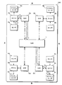
- FIG. 1 It is a schematic diagram which shows one configuration example of the in-vehicle communication system which concerns on this embodiment. It is a block diagram which shows the structure of GW which concerns on Embodiment 1.
- FIG. It is a block diagram which shows the structure of GW which concerns on Embodiment 1.
- FIG. It is a flowchart which shows the procedure of the bypass processing performed by the bypass circuit which concerns on this embodiment.
- the in-vehicle information processing apparatus is connected to a first communication line for communication according to the first communication protocol and a second communication line for communication according to the second communication protocol.
- An in-vehicle relay device that relays communication between one communication line and the second communication line, and can be switched between a sleep state and a non-sleep state. In the non-sleep state, the first communication line and the second communication line and the above.
- the processing unit that performs the process of relaying the communication between the second communication lines and the processing unit are in the sleep state and receive the activation signal of the first communication protocol from the first communication line, the said It includes an activation signal output unit that outputs an activation signal of the second communication protocol to the second communication line.
- the in-vehicle relay device relays the communication between the first communication line that performs communication according to the first communication protocol and the second communication line that performs communication according to the second communication protocol.
- the processing unit that performs relay processing is in the sleep state and receives the activation signal of the first communication protocol from the first communication line
- the activation signal output unit of the in-vehicle relay device transmits the activation signal of the second communication protocol to the second communication. Output to the line.
- the activation signal output unit outputs the activation signal of the second communication protocol to the second communication line to the second communication line even if the processing unit does not shift from the sleep state to the non-sleep state or before the transition. Since the connected device can be activated, it can be expected that the activation signal will be relayed at high speed.
- the start signal output unit outputs a control signal for controlling the start of the processing unit.
- the start signal output unit outputs a control signal that controls the start of the processing unit.
- the processing unit may be activated in response to the control signal from the activation signal output unit, so that it may not be necessary to monitor the presence or absence of the activation signal on the communication line in the sleep state.
- the processing unit is not activated in response to the activation signal, but is activated in response to the control signal.
- the processing unit does not start in response to the start signal received via the communication line, but starts in response to the control signal from the start signal output unit.
- the processing unit is not activated in response to the activation signal, and can be activated only when the activation signal output unit determines that it is necessary.
- the activation signal output unit does not receive a response from the device connected to the second communication line after outputting the activation signal of the second communication protocol to the second communication line, the first operation signal output unit. 2 It is preferable to re-output the activation signal of the communication protocol.
- the activation signal output unit is the activation signal. Retransmit. Thereby, even if the start-up fails for some reason, the possibility that the desired device is started up by the start-up signal output unit retransmitting the start-up signal can be increased.
- a plurality of the second communication lines are connected, and the activation signal output unit performs the second communication based on the information accompanying the activation signal of the first communication protocol received from the first communication line. It is preferable to select which of the second communication lines the protocol activation signal is output to.
- a plurality of second communication lines are connected to the in-vehicle relay device.
- the activation signal output unit does not output the activation signal of the second communication protocol to all the second communication lines, but of the first communication protocol.
- the second communication line that outputs the activation signal of the second communication protocol is selected based on the information accompanying the activation signal. As a result, it is possible to avoid starting unnecessary devices.
- An analog that is interposed between the second communication line and the processing unit can be switched between a sleep state and a non-sleep state, and is transmitted and received via the second communication line in the non-sleep state. It is preferable to include a conversion unit that converts a signal and a digital signal input / output to the processing unit, and the activation signal output unit outputs a control signal that controls activation of the conversion unit.
- the in-vehicle relay device includes a conversion unit that converts an analog signal and a digital signal between the processing unit and the second communication line, and the conversion unit can switch between a sleep state and a non-sleep state. Is.
- the start-up signal output unit outputs a control signal that controls the start-up of this conversion unit. As a result, it is possible to reduce the power consumption of the conversion unit of the in-vehicle relay device.
- the activation signal output unit receives the activation signal of the second communication protocol from the second communication line, it is preferable that the activation signal output unit outputs the activation signal of the first communication protocol to the first communication line. ..
- the activation signal output unit when the activation signal of the second communication protocol is received from the second communication line, the activation signal output unit outputs the activation signal of the first communication protocol to the first communication line.
- the start-up signal output unit can relay the start-up signal in both directions of the first communication line and the second communication line.
- the first communication line that performs communication according to the first communication protocol and the second communication line that performs communication according to the second communication protocol are connected, and the first communication is described.
- the processing unit performs the first communication line and the first communication line.
- the second communication protocol is performed when the processing for relaying the communication between the two communication lines is performed, the processing unit is in the sleep state, and the activation signal of the first communication protocol is received from the first communication line. Is output to the second communication line.
- the activation signal is relayed at high speed as in the aspect (1).
- FIG. 1 is a schematic diagram showing a configuration example of an in-vehicle communication system according to the present embodiment.
- the in-vehicle communication system according to the present embodiment includes a central GW (gateway) 1, a plurality of peripheral GWs 2a to 2d, a plurality of ECUs 3a to 3d, a plurality of sensors 4a to 4d, and a plurality of actuators 5a to 5d.
- FIG. 1 it is assumed that the front-rear, left-right directions of the vehicle 100 correspond to the up-down, left-right directions in the figure.
- GW1 is a relay device arranged in the center of the vehicle 100.
- four GWs 2a to 2d are connected to the GW1 via communication lines.
- the arrow indicated by the thick alternate long and short dash line in this figure is a communication line that performs communication according to the Ethernet (registered trademark) communication protocol.
- the GW 1 and the four GWs 2a to 2d communicate according to the Ethernet communication protocol.
- the GW 1 performs a process of relaying message transmission / reception between the GWs 2a and 2d by transmitting a message received from any of the GWs 2a to 2d to the other GWs 2a to 2d.
- GW2 is a relay device arranged in the peripheral part of the vehicle.
- the GW2a is arranged on the left front side of the vehicle 100
- the GW2b is arranged on the right front side
- the GW2c is arranged on the right rear side
- the GW2d is arranged on the left rear side.
- ECUs 3a to 3d arranged in the vicinity are connected to the GWs 2a to 2d, respectively.
- one ECU 3a to 3d is connected to each of the GWs 2a to 2d, but a plurality of ECUs 3a to 3d may be connected to the GWs 2a to 2d.
- the arrows shown by solid lines in this figure are communication lines that perform communication according to the communication protocol of CAN (Controller Area Network).
- the GWs 2a to 2d and the ECUs 3a to 3d communicate according to the CAN communication protocol.
- the GWs 2a to 2d transmit the messages received from the ECUs 3a to 3d to the GW1 and transmit the messages received from the GW1 to the ECUs 3a to 3d to relay the message transmission / reception between the GW1 and the ECUs 3a to 3d. ..
- the GWs 2a to 2d perform communication with the GW1 according to the Ethernet communication protocol, and communicate with the ECUs 3a to 3d according to the CAN communication protocol. Therefore, the GWs 2a to 2d convert the communication protocol when relaying the message.
- the GWs 2a to 2d convert the message according to the CAN communication protocol received from the ECUs 3a to 3d into a message according to the Ethernet communication protocol and transmit it to the GW1.
- the GWs 2a to 2d convert the message according to the Ethernet communication protocol received from the GW1 into a message according to the CAN communication protocol and transmit the message to the ECUs 3a to 3d.
- Sensors 4a to 4d are connected to each of the ECUs 3a to 3d as input devices for inputting information, and actuators 5a to 5d are connected as devices to be controlled.
- the input devices connected to the ECUs 3a to 3d are not limited to the sensors 4a to 4d, and may be various devices such as switches operated by the user, for example.
- the devices to be controlled to which the ECUs 3a to 3d are connected are not limited to the actuators 5a to 5d, and may be various devices such as a motor or a light. Both the sensors 4a to 4d and the actuators 5a to 5d may not be connected to the ECUs 3a to 3d, or only one of the sensors 4a to 4d or the actuators 5a to 5d may be connected.
- the ECUs 3a to 3d perform a process of controlling the operation of the actuators 5a to 5d to be controlled according to various physical quantities detected by the sensors 4a to 4d.
- the sensors 4a to 4d input analog or digital electric signals according to the physical quantity which is the detection result to the ECUs 3a to 3d via the signal line.
- the ECUs 3a to 3d input analog or digital electric signals according to the control amount of the actuators 5a to 5d to the actuators 5a to 5d via signal lines.
- the signal line connecting the ECUs 3a to 3d, the sensors 4a to 4d, and the actuators 5a to 5d is shown as a broken line arrow.
- the devices such as GW1, GW2a to 2d and ECU3a to 3d included in the in-vehicle communication system according to the present embodiment include, for example, when the engine of the vehicle 100 is stopped or when the ignition switch is switched to the off state. It shifts to the sleep state to reduce power consumption. After that, when it becomes necessary to start the device and start the process for some reason, a wake-up signal (start-up signal) is exchanged between the devices, and each device is started in response to the wake-up signal.
- start-up signal a wake-up signal
- FIG. 1 an example of an information transmission path when it becomes necessary to activate the actuator 5c based on the detection result of the sensor 4a is shown by a thick arrow with hatching.
- the detection result of the sensor 4a is input to the ECU 3a, and the ECU 3a transmits a wake-up signal based on the detection result.
- the wake-up signal transmitted by the ECU 3a is received by the GW 2a, and the GW 2a transmits the wake-up signal to the GW 1.
- the GW1 that has received the wakeup signal from the GW2a transmits the wakeup signal to the GW2c. At this time, the GW1 may also transmit a wakeup signal to the GWs 2b and 2d.
- the GW 2c that has received the wake-up signal from the GW 1 transmits the wake-up signal to the ECU 3c.
- the ECU 3c Upon receiving the wake-up signal from the GW 2c, the ECU 3c is activated in response to the wake-up signal to operate the actuator 5c.
- GW2a, GW1 and GW2c are activated in response to the reception of the wakeup signal, and the wakeup signal is relayed after shifting from the sleep state to the non-sleep state. Therefore, there is a possibility that it may take a long time from the detection of the activation factor by the sensor 4a to the operation of the actuator 5c.
- the GW2a and 2c do not wait for the activation of the microcomputer or the like even when the microcomputer (microcontroller or microcomputer) performing the relay processing is in the sleep state.
- the received wakeup signal is bypassed and relayed.
- the GW1 may be relayed by bypassing the wake signal.
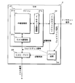
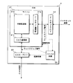
- the GW 2 includes a microcomputer 21, an Ethernet PHY (PHYsical layer) 22, a CAN-PHY 23, a bypass circuit 24, and the like.
- the microcomputer 21, Ethernet PHY22, CAN-PHY23, and bypass circuit 24 are mounted on the circuit board of the GW2 as individual ICs (Integrated Circuits), but the present invention is not limited to this. ..
- any or all of the microcomputer 21, Ethernet PHY22, CAN-PHY23, and bypass circuit 24 may be mounted on the circuit board of the GW2 as one IC.
- Each functional block of the microcomputer 21, Ethernet PHY 22, CAN-PHY 23, and bypass circuit 24 may be a circuit composed of a plurality of electric components mounted on a circuit board.
- the microcomputer 21 has a processor such as a CPU (Central Processing Unit) or an MPU (Micro-Processing Unit), a ROM (Read Only Memory), a RAM (Random Access Memory), and the like, and executes a program stored in the ROM. Performs various arithmetic processes. In the present embodiment, the microcomputer 21 performs a process of relaying communication between communication lines. In FIG. 2, the relay processing unit 21a is shown as a software-like functional unit that performs relay processing by the microcomputer 21.
- the microcomputer 21 has an Ethernet communication unit 21b that performs communication processing according to the Ethernet communication protocol, and a CAN communication unit 21c that performs communication processing according to the CAN communication protocol.
- the Ethernet communication unit 21b When the Ethernet communication unit 21b receives a message according to the Ethernet communication protocol, the Ethernet communication unit 21b acquires the data included in this message and gives it to the relay processing unit 21a. When data to be transmitted from the relay processing unit 21a to another device is given, the Ethernet communication unit 21b transmits this data as a message according to the Ethernet communication protocol.
- the CAN communication unit 21c when the CAN communication unit 21c receives a message according to the CAN communication protocol, the CAN communication unit 21c acquires the data included in this message and gives it to the relay processing unit 21a. When the relay processing unit 21a gives data to be transmitted to another device, the CAN communication unit 21c transmits this data as a message according to the CAN communication protocol.
- the microcomputer 21 can switch between the sleep state and the wake-up state.
- the microcomputer 21 performs the above-mentioned relay processing of the relay processing unit 21a, the communication processing of the Ethernet communication unit 21b, the communication processing of the CAN communication unit 21c, and the like.
- the microcomputer 21 does not perform these processes, for example, stops the oscillation of the clock signal for operation to reduce the power consumption.
- the microcomputer 21 determines a condition such as the engine of the vehicle 100 being stopped or the ignition switch being switched to the off state, and makes a transition from the wake-up state to the sleep state. The transition from the sleep state to the wake-up state of the microcomputer 21 is performed by the start control signal from the bypass circuit 24.
- the Ethernet PHY 22 is an IC that converts an analog electric signal on a communication line and a digital signal handled by the microcomputer 21.
- the Ethernet PHY 22 samples and acquires the potential of the Ethernet communication line connected to the GW 2, and outputs it as a digital signal to the microcomputer 21.
- the Ethernet PHY 22 converts the message given by the microcomputer 21 into an electric signal and outputs the message to the Ethernet communication line.
- the Ethernet PHY 22 can switch between the sleep state and the wake-up state. In the wake-up state, the Ethernet PHY 22 performs the above-mentioned conversion processing between the analog signal and the digital signal.
- the Ethernet PHY 22 performs a process of giving an analog signal on the communication line to the microcomputer 21 as a digital signal, but does not output the analog signal to the communication line. Switching between the sleep state and the wake-up state of the Ethernet PHY 22 is performed by a start control signal from the bypass circuit 24.
- the CAN-PHY 23 is an IC that converts an analog electric signal on a communication line and a digital signal handled by the microcomputer 21.
- the CAN-PHY 23 samples and acquires the potential of the CAN communication line connected to the GW 2, and outputs it as a digital signal to the microcomputer 21.
- the CAN-PHY 23 converts the message given by the microcomputer 21 into an electric signal and outputs the message to the CAN communication line.
- the CAN-PHY 23 can switch between the sleep state and the wake-up state. In the wake-up state, the CAN-PHY 23 performs the above-mentioned conversion processing between the analog signal and the digital signal.
- the CAN-PHY 23 performs a process of giving an analog signal on the communication line to the microcomputer 21 as a digital signal, but does not output the analog signal to the communication line. Switching between the sleep state and the wake-up state of the CAN-PHY 23 is performed by a start control signal from the bypass circuit 24.
- the bypass circuit 24 performs a process of bypassing and relaying the wakeup signal when the microcomputer 21 is in the sleep state.
- a wake-up signal (wake-up signal according to the Ethernet communication protocol) is received via the Ethernet communication line
- the bypass circuit 24 wakes up to the CAN communication line (wake-up signal according to the CAN communication protocol).
- the signal for outputting (up signal) is indicated by a broken arrow.
- FIG. 3 when a wakeup signal (wakeup signal according to the CAN communication protocol) is received via the CAN communication line, the bypass circuit 24 wakes up to the Ethernet communication line (wake according to the Ethernet communication protocol).
- the signal when the (up signal) is output is indicated by the broken arrow.
- the bypass circuit 24 monitors the Ethernet communication line when the microcomputer 21 is in the sleep state. When the bypass circuit 24 detects a wake-up signal on the Ethernet communication line, it activates CAN-PHY23 and gives a wake-up signal to output the wake-up signal to the CAN communication line. At this time, the bypass circuit 24 activates the microcomputer 21.
- the bypass circuit 24 monitors the communication line of the CAN when the microcomputer 21 is in the sleep state. When the bypass circuit 24 detects a wake-up signal on the CAN communication line, it activates the Ethernet PHY 22 and gives the wake-up signal to output the wake-up signal to the Ethernet communication line. At this time, the bypass circuit 24 activates the microcomputer 21.
- the bypass circuit 24 may always operate without switching between the sleep state and the wake-up state, and may have a configuration capable of switching between the sleep state and the wake-up state. In any case, the bypass circuit 24 is given a signal or the like indicating whether the microcomputer 21 is in the sleep state or the wake-up state from the microcomputer 21. When switching the state, the bypass circuit 24 transitions to the sleep state when the microcomputer 21 transitions to the wake-up state, and transitions to the wake-up state when the microcomputer 21 transitions to the sleep state.
- Ethernet wake-up signal for example, a signal based on the Ethernet Wake-on-LAN technology can be adopted.
- Wake-on-LAN a desired device can be activated by sending a message containing a specific pattern of data called a magic packet.
- a wake-up signal of the CAN for example, a dominant signal output for a predetermined time may be adopted.
- the bypass circuit 24 receives a magic packet message on the Ethernet communication line, it outputs a dominant for a predetermined time from the CAN communication line.
- the bypass circuit 24 detects a dominant for a predetermined time on the CAN communication line, the bypass circuit 24 transmits a message including a magic packet from the Ethernet communication line.
- the wake-up signal may have any configuration.
- the bypass circuit 24 has a function of retransmitting the wakeup signal.
- the bypass circuit 24 transmits a wake-up signal to the Ethernet communication line or the CAN communication line, and then determines the presence or absence of a response signal transmitted from a device (device such as ECU3 or GW1) connected to the communication line. judge.
- a device device such as ECU3 or GW1 connected to the communication line. judge.
- the bypass circuit 24 retransmits the wakeup signal to this communication line.
- a dominant signal output for a predetermined time can be adopted as the response signal to the wakeup signal.
- the bypass circuit 24 is in the dominant signal state of the communication line after finishing its own dominant output. By detecting the presence, it can be determined that the response signal has been output.
- a message containing a specific pattern of data can be adopted as a response signal.
- the response signal may have any configuration.
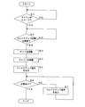
- FIG. 4 is a flowchart showing a procedure of bypass processing performed by the bypass circuit 24 according to the present embodiment.
- the bypass circuit 24 determines whether or not the microcomputer 21 is in the sleep state (step S1). When the microcomputer 21 is not in the sleep state (S1: NO), the bypass circuit 24 waits until the microcomputer 21 transitions to the sleep state.
- the bypass circuit 24 determines whether or not a wakeup signal has been received via the Ethernet communication line (step S2). When the wake-up signal is not received (S2: NO), the bypass circuit 24 waits until the wake-up signal is received. When the wakeup signal is received (S2: YES), the bypass circuit 24 outputs a start control signal for activating CAN-PHY23 (step S3). The bypass circuit 24 outputs a start control signal for starting the microcomputer 21 (step S4).
- the bypass circuit 24 outputs the wakeup signal to the CAN communication line by giving the wakeup signal according to the CAN communication protocol to the CAN-PHY23 (step S5). At this time, the bypass circuit 24 outputs the wake-up signal without waiting for the completion of switching from the sleep state to the wake-up state of the microcomputer 21.
- the bypass circuit 24 determines whether or not the response signal from the device connected to the communication line of the CAN that outputs the wakeup signal has been received by the elapse of a predetermined time (step). S6). If the response signal has not been received even after the lapse of the predetermined time (S7: NO), the bypass circuit 24 outputs a wakeup signal to this communication line (step S7), and returns the process to step S6. When the response signal is received by the elapse of the predetermined time (S6: YES), the bypass circuit 24 ends the bypass processing of the wakeup signal.
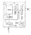
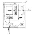
- FIG. 5 is a block diagram showing the configuration of GW2 according to the second embodiment.
- the bypass circuit 24 does not directly acquire the wake-up signal from the Ethernet communication line, but the Ethernet PHY 22 acquires the wake-up signal converted into a digital signal.
- the bypass circuit 24 according to the second embodiment does not acquire the wakeup signal directly from the communication line of the CAN, but acquires the wakeup signal converted into a digital signal by the CAN-PHY23.
- the configuration of the bypass circuit 24 according to the second embodiment is the same as the configuration of the bypass circuit 24 according to the first embodiment.
- the bypass circuit 24 needs to include a conversion circuit from an analog signal to a digital signal in the bypass circuit 24 by acquiring a wakeup signal converted into a digital signal by the Ethernet PHY 22 and CAN-PHY 23. Therefore, the bypass circuit 24 can be expected to be downsized.
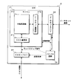
- FIG. 6 is a block diagram showing the configuration of GW2 according to the third embodiment.
- the GW 2 according to the third embodiment does not output the wake-up signal to the CAN-PHY23, but directly outputs the wake-up signal to the communication line of the CAN.
- the bypass circuit 24 according to the third embodiment does not output the wakeup signal to the Ethernet PHY 22, but outputs the wakeup signal directly to the Ethernet communication line. Since the bypass circuit 24 according to the third embodiment outputs the wakeup signal directly to the CAN communication line or the Ethernet communication line, it is necessary to activate the CAN-PHY23 or the Ethernet PHY22 before outputting the wakeup signal. Absent.
- the bypass circuit 24 according to the third embodiment may be configured not to output the activation control signals of the CAN-PHY 23 and the Ethernet PHY 22.
- the bypass circuit 24 according to the third embodiment outputs a wakeup signal as an analog signal.
- the configuration of the bypass circuit 24 according to the third embodiment is the same as the configuration of the bypass circuit 24 according to the first embodiment.
- bypass circuit 24 can directly bypass and relay the wakeup signal between the Ethernet communication line and the CAN communication line, the wakeup signal is relayed more quickly. Can be expected.
- FIG. 7 is a block diagram showing the configuration of GW2 according to the fourth embodiment.
- the bypass circuit 24 does not acquire the wake-up signal from the Ethernet communication line, but acquires the wake-up signal from the Ethernet PHY 22. Therefore, the Ethernet PHY 22 according to the seventh embodiment has a function of outputting a signal for notifying the wakeup signal to the bypass circuit 24 when the wakeup signal is detected on the Ethernet communication line.
- This signal output by Ethernet PHY2 may be input to the microcomputer 21 as a start-up signal.
- the bypass circuit 24 activates the CAN-PHY23 to output the wakeup signal, and outputs the wakeup signal to the communication line of the CAN.
- the CAN-PHY23 has a function of outputting a signal for notifying the wakeup signal to the bypass circuit 24 when a wakeup signal is detected on the communication line of the CAN. ..
- This signal output by the CAN-PHY 23 may be input to the microcomputer 21 as a start signal.
- the bypass circuit 24 activates the Ethernet PHY 22 to output the wake-up signal, and outputs the wake-up signal to the Ethernet communication line.
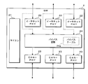
- FIG. 8 is a block diagram showing the configuration of GW2 according to the fifth embodiment.
- the GW 2 according to the fifth embodiment includes a plurality of Ethernet PHY 22 and a plurality of CAN-PHY 23, and the relay processing unit 21a of the microcomputer 21 is located between the plurality of Ethernet communication lines and the plurality of CAN communication lines. Relay the message with. At this time, the relay processing unit 21a determines the relay destination of the message based on the ID attached to the message and the like.
- the microcomputer 21 stores in advance a routing table or the like in which the ID and the relay destination are associated with each other in the ROM. Note that in FIG. 8, the route of message relay by the microcomputer 21 is not shown.
- the bypass circuit 24 of the GW 2 monitors the presence or absence of a wake-up signal for each Ethernet communication line.
- the bypass circuit 24 detects a wakeup signal on any of the Ethernet communication lines, the bypass circuit 24 outputs the wakeup signal to one or more CAN-PHY 23s, thereby transmitting the wakeup signal to the communication of one or more CANs. Bypass to the line and relay.
- the bypass circuit 24 may transmit the wakeup signal to the Ethernet communication line other than the Ethernet communication line that received the wakeup signal.
- the bypass circuit 24 has a bypass table 24a for determining a relay destination for bypassing and relaying the wakeup signal.
- the bypass circuit 24 has a non-volatile memory element such as an EEPROM (Electrically Erasable Programmable Read Only Memory), and stores the bypass table 24a in this memory element.
- EEPROM Electrically Erasable Programmable Read Only Memory
- the wake-up signal of the Ethernet communication protocol transmitted / received in the in-vehicle communication system includes, for example, an ID of the source ECU 3, an ID of the destination ECU 3, or an ID indicating the type of the wake-up signal. Identification information such as is attached.
- the GW1 and GW2 and the like include the identification information in the magic packet and transmit the message.
- the bypass circuit 24 refers to the bypass table 24a based on the identification information associated with the wakeup signal received on any of the Ethernet communication lines, and the communication line of the destination CAN set in the bypass table 24a (the bypass circuit 24). And the Ethernet communication line) to send a wakeup signal.
- the bypass circuit 24 monitors the presence or absence of a wakeup signal for each CAN communication line.
- the bypass circuit 24 detects a wakeup signal on one of the CAN communication lines, it outputs the wakeup signal to one or more Ethernet PHY22s to output the wakeup signal to one or more Ethernet communication lines.
- the bypass circuit 24 may transmit the wakeup signal to the communication line of the CAN other than the communication line of the CAN that has received the wakeup signal.
- the wake-up signal of the CAN communication protocol transmitted and received in the in-vehicle communication system includes, for example, an ID of the source ECU 3, an ID of the transmission destination ECU 3, or an ID indicating the type of the wake-up signal. Identification information such as is attached.
- the GW2, ECU3, etc. transmit the dominant signal for the predetermined time, and then transmit identification information following the dominant signal. ..
- the bypass circuit 24 receives the dominant signal for a predetermined time on the CAN communication line, and then receives the identification information following the dominant signal.
- the bypass circuit 24 refers to the bypass table 24a based on the received identification information, and transmits a wakeup signal to the transmission destination Ethernet communication line (and CAN communication line) set in the bypass table 24a. ..
- GW2 In GW2 according to the fifth embodiment, a plurality of Ethernet communication lines and a plurality of CAN communication lines are connected, and a message is relayed between the plurality of communication lines.
- the bypass circuit 24 of the GW 2 according to the fifth embodiment bypasses the wake-up signal received on one of the communication lines and transmits the wake-up signal to the other communication line. At this time, the bypass circuit 24 determines the communication line for transmitting the wakeup signal by referring to the preset bypass table 24a based on the identification information accompanying the wakeup signal.
- FIG. 8 shows a configuration in which three Ethernet communication lines are connected to the GW2 and three CAN communication lines are connected, but the number of communication lines is an example and is limited to this. is not it.
- the start signal from the bypass circuit 24 to the microcomputer 21 and the start signal from the bypass circuit 24 to the Ethernet PHY 22 and the CAN-PHY 23 are not shown.
- the bypass circuit 24 according to the fifth embodiment may determine whether or not to activate the microcomputer 21 based on, for example, the identification information accompanying the wakeup signal. In this case, information indicating whether or not to start the microcomputer 21 is stored in the bypass table 24a in association with the identification information of the wakeup signal.
- the GW2 transmits / receives a message between an Ethernet communication line that communicates according to the Ethernet communication protocol and a CAN communication line that communicates according to the CAN communication protocol. Relay.
- the bypass circuit 24 of the GW2 transmits the wakeup signal of the CAN communication protocol to the CAN. Output to the communication line.
- the bypass circuit 24 outputs the wake-up signal of the CAN communication protocol to the CAN communication line to the CAN communication line even if the microcomputer 21 does not transition from the sleep state to the wake-up state or before the transition. Since the connected device can be activated, it can be expected that the wakeup signal is relayed at high speed.
- the bypass circuit 24 outputs a control signal for activating the microcomputer 21 from the sleep state to the wake-up state.
- the microcomputer 21 may be activated in response to the control signal from the bypass circuit 24, so that it may not be necessary to monitor the presence or absence of the wakeup signal on the communication line in the sleep state.
- the microcomputer 21 does not start in response to the wake-up signal directly received via the communication line, but starts in response to the signal from the bypass circuit 24. As a result, the microcomputer 21 is not activated in response to the wake-up signal, and can be activated only when the bypass circuit 24 determines that it is necessary.
- the GW 2 is a bypass circuit when a response from the ECU 3 or the like connected to the CAN communication line is not received after outputting the wake-up signal of the CAN communication protocol to the CAN communication line. 24 retransmits the wakeup signal. As a result, even if the activation of the ECU 3 or the like in response to the wake-up signal fails for some reason, the bypass circuit 24 retransmits the wake-up signal to increase the possibility that the desired device is activated. Can be done.
- a plurality of CAN communication lines are connected.
- the GW2 bypass circuit 24 receives a wakeup signal from the Ethernet communication line, the GW2 bypass circuit 24 does not output the wakeup signal to all CAN communication lines, but instead outputs the wakeup signal to the wakeup signal received by the Ethernet communication line.
- the CAN communication line that outputs the wakeup signal of the CAN communication protocol is selected. As a result, it is possible to avoid starting unnecessary devices.
- the GW 2 includes a CAN-PHY 23 that converts an analog signal and a digital signal between the communication lines of the microcomputer 21 and the CAN.
- the bypass circuit 24 of the GW 2 outputs a signal for controlling the activation of the CAN-PHY 23. As a result, the power consumption of CAN-PHY23 of GW2 can be reduced.
- the bypass circuit 24 when the wakeup signal of the CAN communication protocol is received from the communication line of the CAN, the bypass circuit 24 outputs the wakeup signal of the Ethernet communication protocol to the Ethernet communication line. As a result, the bypass circuit 24 can bypass and relay the wake-up signal in both directions of the Ethernet communication line and the CAN communication line.
- Ethernet and CAN are mentioned as communication protocols used in the in-vehicle communication system, but the present invention is not limited to this, and various communication protocols other than Ethernet and CAN may be adopted. Further, in the GW2, communication lines of three or more different communication protocols may be connected, and in this case as well, when the bypass circuit 24 receives a wakeup signal of one communication protocol, the other two communication protocols Wake-up signals may be output to each communication line.
- bypass circuit 24 of the GW 2 bypasses the wake-up signal and relays in both directions from the Ethernet communication line to the CAN communication line and from the CAN communication line to the Ethernet communication line.
- the bypass circuit 24 bypasses and relays the wake-up signal from either the Ethernet communication line to the CAN communication line or from the CAN communication line to the Ethernet communication line, and the microcomputer 21 wakes the other.
- the up signal may be relayed.
- the GW1 may also be configured to bypass and relay the wakeup signal by providing the bypass circuit 24 in the same manner. Since the GW1 shown in FIG. 1 has a configuration in which only Ethernet communication lines are connected, the bypass circuit 24 directly physically or electrically connects a plurality of communication lines using circuit elements such as switches or relays. Therefore, the wake-up signal may be bypassed and relayed.
- Each device in the in-vehicle communication system includes a computer including a microprocessor, ROM, RAM, and the like.
- An arithmetic processing unit such as a microprocessor may read a computer program including a part or all of each step of a sequence diagram or a flowchart as shown in FIG. 4 from a storage unit such as a ROM or a RAM and execute the program.
- the computer programs of these plurality of devices can be installed from an external server device or the like. Further, the computer programs of these plurality of devices are distributed in a state of being stored in a recording medium such as a CD-ROM, a DVD-ROM, or a semiconductor memory, respectively.
Abstract
L'invention concerne un dispositif de relais embarqué et un procédé de relais avec lesquels le relais à grande vitesse d'un signal de démarrage peut être attendu entre des lignes de communication employant des protocoles de communication différents. Un dispositif de relais embarqué selon le présent mode de réalisation dans lequel sont connectées une première ligne de communication, destinée à réaliser une communication selon un premier protocole de communication, et une ligne de communication, destinée à réaliser une communication selon un différents protocole de communication, et dans lequel des communications sont relayées entre la première ligne de communication et la différents ligne de communication. Le dispositif de relais embarqué est pourvu : d'une unité de traitement qui peut commuter entre un état de sommeil et un état de non-sommeil et qui, dans l'état de non-sommeil, effectue le processus de relayage des communications entre la première ligne de communication et la différents ligne de communication ; et une unité de sortie de signal de démarrage qui, lorsque l'unité de traitement se trouve dans l'état de veille et reçoit un signal de démarrage du premier protocole de communication de la part de la première ligne de communication, délivre un signal de démarrage du différents protocole de communication à la différents ligne de communication.
Priority Applications (2)
| Application Number | Priority Date | Filing Date | Title |
|---|---|---|---|
| CN202080079624.0A CN114731298A (zh) | 2019-11-22 | 2020-11-10 | 车载中继装置及中继方法 |
| US17/756,235 US20220417346A1 (en) | 2019-11-22 | 2020-11-20 | In-Vehicle Relay Device and Relay Method |
Applications Claiming Priority (2)
| Application Number | Priority Date | Filing Date | Title |
|---|---|---|---|
| JP2019211779A JP7207278B2 (ja) | 2019-11-22 | 2019-11-22 | 車載中継装置及び中継方法 |
| JP2019-211779 | 2019-11-22 |
Publications (1)
| Publication Number | Publication Date |
|---|---|
| WO2021100548A1 true WO2021100548A1 (fr) | 2021-05-27 |
Family
ID=75965482
Family Applications (1)
| Application Number | Title | Priority Date | Filing Date |
|---|---|---|---|
| PCT/JP2020/041873 WO2021100548A1 (fr) | 2019-11-22 | 2020-11-10 | Dispositif de relais embarqué et procédé de relais |
Country Status (4)
| Country | Link |
|---|---|
| US (1) | US20220417346A1 (fr) |
| JP (1) | JP7207278B2 (fr) |
| CN (1) | CN114731298A (fr) |
| WO (1) | WO2021100548A1 (fr) |
Families Citing this family (2)
| Publication number | Priority date | Publication date | Assignee | Title |
|---|---|---|---|---|
| KR102611371B1 (ko) * | 2018-12-13 | 2023-12-06 | 엘지전자 주식회사 | 차량용 시스템 및 방법 |
| JP2024041473A (ja) * | 2022-09-14 | 2024-03-27 | 株式会社デンソー | 車載通信システムおよび通信ノード |
Citations (2)
| Publication number | Priority date | Publication date | Assignee | Title |
|---|---|---|---|---|
| JP2014165746A (ja) * | 2013-02-26 | 2014-09-08 | Denso Corp | データ中継装置 |
| WO2019087591A1 (fr) * | 2017-10-31 | 2019-05-09 | 株式会社デンソー | Système de communication et passerelle |
Family Cites Families (10)
| Publication number | Priority date | Publication date | Assignee | Title |
|---|---|---|---|---|
| JP2005045521A (ja) * | 2003-07-22 | 2005-02-17 | Nissan Motor Co Ltd | 車載ゲートウェイ装置 |
| JP2005086692A (ja) * | 2003-09-10 | 2005-03-31 | Calsonic Kansei Corp | ゲートウェイ装置 |
| JP2008227591A (ja) * | 2007-03-08 | 2008-09-25 | Auto Network Gijutsu Kenkyusho:Kk | 車載用の中継接続ユニット |
| US9152195B2 (en) * | 2013-01-21 | 2015-10-06 | Lenovo (Singapore) Pte. Ltd. | Wake on cloud |
| US9452732B1 (en) * | 2015-03-30 | 2016-09-27 | Ford Global Technologies, Llc | Vehicle key off load reduction via off-board sensor |
| JP6699610B2 (ja) * | 2016-12-20 | 2020-05-27 | 株式会社オートネットワーク技術研究所 | 車車間通信システム、路側通信装置及び車車間通信方法 |
| CN106888491B (zh) * | 2016-12-22 | 2020-04-24 | 南京航空航天大学 | 一种基于相长干涉的无线传感器网络按需快速唤醒方法 |
| JP6881231B2 (ja) * | 2017-10-25 | 2021-06-02 | トヨタ自動車株式会社 | 車載中継装置、情報処理方法、プログラム、中継装置、及び情報処理システム |
| EP3729766A1 (fr) * | 2017-12-24 | 2020-10-28 | Arilou Information Security Technologies Ltd. | Système et procédé de détection de logiciel malveillant basée sur un tunnel |
| CN108958106B (zh) * | 2018-06-27 | 2021-08-31 | 威凯检测技术有限公司 | 一种电动汽车控制器休眠唤醒系统及控制方法 |
-
2019
- 2019-11-22 JP JP2019211779A patent/JP7207278B2/ja active Active
-
2020
- 2020-11-10 CN CN202080079624.0A patent/CN114731298A/zh active Pending
- 2020-11-10 WO PCT/JP2020/041873 patent/WO2021100548A1/fr active Application Filing
- 2020-11-20 US US17/756,235 patent/US20220417346A1/en active Pending
Patent Citations (2)
| Publication number | Priority date | Publication date | Assignee | Title |
|---|---|---|---|---|
| JP2014165746A (ja) * | 2013-02-26 | 2014-09-08 | Denso Corp | データ中継装置 |
| WO2019087591A1 (fr) * | 2017-10-31 | 2019-05-09 | 株式会社デンソー | Système de communication et passerelle |
Also Published As
| Publication number | Publication date |
|---|---|
| JP2021083059A (ja) | 2021-05-27 |
| CN114731298A (zh) | 2022-07-08 |
| US20220417346A1 (en) | 2022-12-29 |
| JP7207278B2 (ja) | 2023-01-18 |
Similar Documents
| Publication | Publication Date | Title |
|---|---|---|
| JP5776779B2 (ja) | 車載ゲートウェイ装置及び車両用通信システム | |
| JP4483694B2 (ja) | 車両用通信システム | |
| JP6464901B2 (ja) | 車載通信システム及び中継装置 | |
| WO2021100548A1 (fr) | Dispositif de relais embarqué et procédé de relais | |
| JP2002026957A (ja) | 多重通信システム | |
| JP2015081021A (ja) | 車載ネットワークシステム、管理装置 | |
| WO2016111213A1 (fr) | Dispositif relais embarqué et procédé de relais | |
| JP5286659B2 (ja) | 車載装置中継システム、車載装置中継方法及び中継装置 | |
| JP6127944B2 (ja) | 車載ネットワークシステム | |
| CN112208467B (zh) | 车载网络系统 | |
| JP2011004276A (ja) | 車載ネットワーク、データ送信方法 | |
| JP2005045521A (ja) | 車載ゲートウェイ装置 | |
| JP4954832B2 (ja) | 車載用通信システム | |
| JP2009124480A (ja) | 車載ゲートウェイ及び車両用通信システム | |
| JP7463870B2 (ja) | 車載装置、車載通信システムおよび通信制御方法 | |
| JP2006192970A (ja) | 車載用通信接続装置および車載通信システム | |
| JP5359449B2 (ja) | 中継システム及び制御装置 | |
| JP5614365B2 (ja) | データ中継装置、車載ネットワーク | |
| JP2004122993A (ja) | 車載機器接続システム | |
| JPH0630472A (ja) | 多重伝送装置 | |
| JP2010258635A (ja) | 制御装置 | |
| JP2011093377A (ja) | 電源制御システム及び電子装置 | |
| JP3310020B2 (ja) | 車両用多重伝送装置 | |
| US20240089142A1 (en) | Vehicle-mounted apparatus and a method for relaying | |
| WO2022163392A1 (fr) | Dispositif embarqué et procédé de détection de changement d'état |
Legal Events
| Date | Code | Title | Description |
|---|---|---|---|
| 121 | Ep: the epo has been informed by wipo that ep was designated in this application |
Ref document number: 20891213 Country of ref document: EP Kind code of ref document: A1 |
|
| NENP | Non-entry into the national phase |
Ref country code: DE |
|
| 122 | Ep: pct application non-entry in european phase |
Ref document number: 20891213 Country of ref document: EP Kind code of ref document: A1 |