WO2021100548A1 - Onboard relay device and relay method - Google Patents
Onboard relay device and relay method Download PDFInfo
- Publication number
- WO2021100548A1 WO2021100548A1 PCT/JP2020/041873 JP2020041873W WO2021100548A1 WO 2021100548 A1 WO2021100548 A1 WO 2021100548A1 JP 2020041873 W JP2020041873 W JP 2020041873W WO 2021100548 A1 WO2021100548 A1 WO 2021100548A1
- Authority
- WO
- WIPO (PCT)
- Prior art keywords
- communication
- signal
- communication line
- sleep state
- communication protocol
- Prior art date
Links
Images
Classifications
-
- H—ELECTRICITY
- H04—ELECTRIC COMMUNICATION TECHNIQUE
- H04L—TRANSMISSION OF DIGITAL INFORMATION, e.g. TELEGRAPHIC COMMUNICATION
- H04L69/00—Network arrangements, protocols or services independent of the application payload and not provided for in the other groups of this subclass
- H04L69/08—Protocols for interworking; Protocol conversion
-
- H—ELECTRICITY
- H04—ELECTRIC COMMUNICATION TECHNIQUE
- H04L—TRANSMISSION OF DIGITAL INFORMATION, e.g. TELEGRAPHIC COMMUNICATION
- H04L12/00—Data switching networks
- H04L12/28—Data switching networks characterised by path configuration, e.g. LAN [Local Area Networks] or WAN [Wide Area Networks]
- H04L12/40—Bus networks
- H04L12/407—Bus networks with decentralised control
- H04L12/413—Bus networks with decentralised control with random access, e.g. carrier-sense multiple-access with collision detection (CSMA-CD)
-
- H—ELECTRICITY
- H04—ELECTRIC COMMUNICATION TECHNIQUE
- H04L—TRANSMISSION OF DIGITAL INFORMATION, e.g. TELEGRAPHIC COMMUNICATION
- H04L12/00—Data switching networks
- H04L12/28—Data switching networks characterised by path configuration, e.g. LAN [Local Area Networks] or WAN [Wide Area Networks]
- H04L12/46—Interconnection of networks
-
- H—ELECTRICITY
- H04—ELECTRIC COMMUNICATION TECHNIQUE
- H04L—TRANSMISSION OF DIGITAL INFORMATION, e.g. TELEGRAPHIC COMMUNICATION
- H04L12/00—Data switching networks
- H04L12/66—Arrangements for connecting between networks having differing types of switching systems, e.g. gateways
-
- H—ELECTRICITY
- H04—ELECTRIC COMMUNICATION TECHNIQUE
- H04L—TRANSMISSION OF DIGITAL INFORMATION, e.g. TELEGRAPHIC COMMUNICATION
- H04L67/00—Network arrangements or protocols for supporting network services or applications
- H04L67/01—Protocols
- H04L67/12—Protocols specially adapted for proprietary or special-purpose networking environments, e.g. medical networks, sensor networks, networks in vehicles or remote metering networks
Definitions
- the present disclosure relates to an in-vehicle relay device and a relay method for relaying communication between a first communication line and a second communication line.
- devices such as an ECU (Electronic Control Unit) and a gateway mounted on a vehicle have a sleep state (a sleep state) that reduces power consumption when it is not necessary to perform processing in a situation such as when the vehicle engine is stopped. Control to shift to the standby state or the standby state, etc. is performed.
- the device in the sleep state receives an activation signal (wake-up signal, etc.) by communication, for example, it shifts from the sleep state to the non-sleep state (wake-up state, active state, etc.) and starts processing.
- an activation signal wake-up signal, etc.
- Patent Document 1 a switching circuit that switches the connection destination of the two networks to either the bypass bus or the controller is used, and in the sleep state, the two networks are connected to the bypass bus and wake up.
- an in-vehicle gateway device that connects two networks to a controller has been proposed.
- the number of devices mounted on vehicles has increased, and the network inside the vehicle has become huge and complicated. Therefore, there is a possibility that a plurality of gateways intervene in the communication path from one device to another device. For example, when one device transmits a start signal, this start signal activates the gateways in the middle in order, the gateway relays the start signals in order, and finally the other device receives the start signal and starts. Therefore, there is a problem that it takes a long time from one device transmitting the start signal to the other device starting the process.
- the in-vehicle gateway device described in Patent Document 1 can directly relay a signal by directly connecting two networks in a sleep state, but this device configuration adopts a communication protocol in which the two networks are different. There is a problem that it cannot be adopted if it is a thing.
- the present disclosure has been made in view of such circumstances, and an object thereof is an in-vehicle relay device that can be expected to relay a start signal at high speed between communication lines adopting different communication protocols.
- the purpose is to provide a relay method.
- a first communication line for communication according to the first communication protocol and a second communication line for communication according to the second communication protocol are connected, and the first communication line and the first communication line and the second communication line for communication according to the second communication protocol are connected.
- An in-vehicle relay device that relays communication between the second communication lines, which can be switched between a sleep state and a non-sleep state, and when the non-sleep state is in the non-sleep state, the first communication line and the second communication line.
- the second communication protocol when the processing unit that performs the process of relaying the communication between the two is in the sleep state and the activation signal of the first communication protocol is received from the first communication line. It is provided with a start signal output unit that outputs the start signal of the above to the second communication line.
- the present application can be realized not only as a device such as an in-vehicle relay device provided with such a characteristic processing unit, but also as a relay method in which the characteristic processing is a step, or the step is executed on a computer. It can be realized as a computer program for making it. It can be realized as a semiconductor integrated circuit that realizes a part or all of these devices, or can be realized as another device or system including these devices.
- the start signal is relayed at high speed between communication lines that employ different communication protocols.
- FIG. 1 It is a schematic diagram which shows one configuration example of the in-vehicle communication system which concerns on this embodiment. It is a block diagram which shows the structure of GW which concerns on Embodiment 1.
- FIG. It is a block diagram which shows the structure of GW which concerns on Embodiment 1.
- FIG. It is a flowchart which shows the procedure of the bypass processing performed by the bypass circuit which concerns on this embodiment.
- the in-vehicle information processing apparatus is connected to a first communication line for communication according to the first communication protocol and a second communication line for communication according to the second communication protocol.
- An in-vehicle relay device that relays communication between one communication line and the second communication line, and can be switched between a sleep state and a non-sleep state. In the non-sleep state, the first communication line and the second communication line and the above.
- the processing unit that performs the process of relaying the communication between the second communication lines and the processing unit are in the sleep state and receive the activation signal of the first communication protocol from the first communication line, the said It includes an activation signal output unit that outputs an activation signal of the second communication protocol to the second communication line.
- the in-vehicle relay device relays the communication between the first communication line that performs communication according to the first communication protocol and the second communication line that performs communication according to the second communication protocol.
- the processing unit that performs relay processing is in the sleep state and receives the activation signal of the first communication protocol from the first communication line
- the activation signal output unit of the in-vehicle relay device transmits the activation signal of the second communication protocol to the second communication. Output to the line.
- the activation signal output unit outputs the activation signal of the second communication protocol to the second communication line to the second communication line even if the processing unit does not shift from the sleep state to the non-sleep state or before the transition. Since the connected device can be activated, it can be expected that the activation signal will be relayed at high speed.
- the start signal output unit outputs a control signal for controlling the start of the processing unit.
- the start signal output unit outputs a control signal that controls the start of the processing unit.
- the processing unit may be activated in response to the control signal from the activation signal output unit, so that it may not be necessary to monitor the presence or absence of the activation signal on the communication line in the sleep state.
- the processing unit is not activated in response to the activation signal, but is activated in response to the control signal.
- the processing unit does not start in response to the start signal received via the communication line, but starts in response to the control signal from the start signal output unit.
- the processing unit is not activated in response to the activation signal, and can be activated only when the activation signal output unit determines that it is necessary.
- the activation signal output unit does not receive a response from the device connected to the second communication line after outputting the activation signal of the second communication protocol to the second communication line, the first operation signal output unit. 2 It is preferable to re-output the activation signal of the communication protocol.
- the activation signal output unit is the activation signal. Retransmit. Thereby, even if the start-up fails for some reason, the possibility that the desired device is started up by the start-up signal output unit retransmitting the start-up signal can be increased.
- a plurality of the second communication lines are connected, and the activation signal output unit performs the second communication based on the information accompanying the activation signal of the first communication protocol received from the first communication line. It is preferable to select which of the second communication lines the protocol activation signal is output to.
- a plurality of second communication lines are connected to the in-vehicle relay device.
- the activation signal output unit does not output the activation signal of the second communication protocol to all the second communication lines, but of the first communication protocol.
- the second communication line that outputs the activation signal of the second communication protocol is selected based on the information accompanying the activation signal. As a result, it is possible to avoid starting unnecessary devices.
- An analog that is interposed between the second communication line and the processing unit can be switched between a sleep state and a non-sleep state, and is transmitted and received via the second communication line in the non-sleep state. It is preferable to include a conversion unit that converts a signal and a digital signal input / output to the processing unit, and the activation signal output unit outputs a control signal that controls activation of the conversion unit.
- the in-vehicle relay device includes a conversion unit that converts an analog signal and a digital signal between the processing unit and the second communication line, and the conversion unit can switch between a sleep state and a non-sleep state. Is.
- the start-up signal output unit outputs a control signal that controls the start-up of this conversion unit. As a result, it is possible to reduce the power consumption of the conversion unit of the in-vehicle relay device.
- the activation signal output unit receives the activation signal of the second communication protocol from the second communication line, it is preferable that the activation signal output unit outputs the activation signal of the first communication protocol to the first communication line. ..
- the activation signal output unit when the activation signal of the second communication protocol is received from the second communication line, the activation signal output unit outputs the activation signal of the first communication protocol to the first communication line.
- the start-up signal output unit can relay the start-up signal in both directions of the first communication line and the second communication line.
- the first communication line that performs communication according to the first communication protocol and the second communication line that performs communication according to the second communication protocol are connected, and the first communication is described.
- the processing unit performs the first communication line and the first communication line.
- the second communication protocol is performed when the processing for relaying the communication between the two communication lines is performed, the processing unit is in the sleep state, and the activation signal of the first communication protocol is received from the first communication line. Is output to the second communication line.
- the activation signal is relayed at high speed as in the aspect (1).
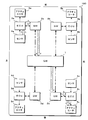
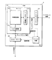
- FIG. 1 is a schematic diagram showing a configuration example of an in-vehicle communication system according to the present embodiment.
- the in-vehicle communication system according to the present embodiment includes a central GW (gateway) 1, a plurality of peripheral GWs 2a to 2d, a plurality of ECUs 3a to 3d, a plurality of sensors 4a to 4d, and a plurality of actuators 5a to 5d.
- FIG. 1 it is assumed that the front-rear, left-right directions of the vehicle 100 correspond to the up-down, left-right directions in the figure.
- GW1 is a relay device arranged in the center of the vehicle 100.
- four GWs 2a to 2d are connected to the GW1 via communication lines.
- the arrow indicated by the thick alternate long and short dash line in this figure is a communication line that performs communication according to the Ethernet (registered trademark) communication protocol.
- the GW 1 and the four GWs 2a to 2d communicate according to the Ethernet communication protocol.
- the GW 1 performs a process of relaying message transmission / reception between the GWs 2a and 2d by transmitting a message received from any of the GWs 2a to 2d to the other GWs 2a to 2d.
- GW2 is a relay device arranged in the peripheral part of the vehicle.
- the GW2a is arranged on the left front side of the vehicle 100
- the GW2b is arranged on the right front side
- the GW2c is arranged on the right rear side
- the GW2d is arranged on the left rear side.
- ECUs 3a to 3d arranged in the vicinity are connected to the GWs 2a to 2d, respectively.
- one ECU 3a to 3d is connected to each of the GWs 2a to 2d, but a plurality of ECUs 3a to 3d may be connected to the GWs 2a to 2d.
- the arrows shown by solid lines in this figure are communication lines that perform communication according to the communication protocol of CAN (Controller Area Network).
- the GWs 2a to 2d and the ECUs 3a to 3d communicate according to the CAN communication protocol.
- the GWs 2a to 2d transmit the messages received from the ECUs 3a to 3d to the GW1 and transmit the messages received from the GW1 to the ECUs 3a to 3d to relay the message transmission / reception between the GW1 and the ECUs 3a to 3d. ..
- the GWs 2a to 2d perform communication with the GW1 according to the Ethernet communication protocol, and communicate with the ECUs 3a to 3d according to the CAN communication protocol. Therefore, the GWs 2a to 2d convert the communication protocol when relaying the message.
- the GWs 2a to 2d convert the message according to the CAN communication protocol received from the ECUs 3a to 3d into a message according to the Ethernet communication protocol and transmit it to the GW1.
- the GWs 2a to 2d convert the message according to the Ethernet communication protocol received from the GW1 into a message according to the CAN communication protocol and transmit the message to the ECUs 3a to 3d.
- Sensors 4a to 4d are connected to each of the ECUs 3a to 3d as input devices for inputting information, and actuators 5a to 5d are connected as devices to be controlled.
- the input devices connected to the ECUs 3a to 3d are not limited to the sensors 4a to 4d, and may be various devices such as switches operated by the user, for example.
- the devices to be controlled to which the ECUs 3a to 3d are connected are not limited to the actuators 5a to 5d, and may be various devices such as a motor or a light. Both the sensors 4a to 4d and the actuators 5a to 5d may not be connected to the ECUs 3a to 3d, or only one of the sensors 4a to 4d or the actuators 5a to 5d may be connected.
- the ECUs 3a to 3d perform a process of controlling the operation of the actuators 5a to 5d to be controlled according to various physical quantities detected by the sensors 4a to 4d.
- the sensors 4a to 4d input analog or digital electric signals according to the physical quantity which is the detection result to the ECUs 3a to 3d via the signal line.
- the ECUs 3a to 3d input analog or digital electric signals according to the control amount of the actuators 5a to 5d to the actuators 5a to 5d via signal lines.
- the signal line connecting the ECUs 3a to 3d, the sensors 4a to 4d, and the actuators 5a to 5d is shown as a broken line arrow.
- the devices such as GW1, GW2a to 2d and ECU3a to 3d included in the in-vehicle communication system according to the present embodiment include, for example, when the engine of the vehicle 100 is stopped or when the ignition switch is switched to the off state. It shifts to the sleep state to reduce power consumption. After that, when it becomes necessary to start the device and start the process for some reason, a wake-up signal (start-up signal) is exchanged between the devices, and each device is started in response to the wake-up signal.
- start-up signal a wake-up signal
- FIG. 1 an example of an information transmission path when it becomes necessary to activate the actuator 5c based on the detection result of the sensor 4a is shown by a thick arrow with hatching.
- the detection result of the sensor 4a is input to the ECU 3a, and the ECU 3a transmits a wake-up signal based on the detection result.
- the wake-up signal transmitted by the ECU 3a is received by the GW 2a, and the GW 2a transmits the wake-up signal to the GW 1.
- the GW1 that has received the wakeup signal from the GW2a transmits the wakeup signal to the GW2c. At this time, the GW1 may also transmit a wakeup signal to the GWs 2b and 2d.
- the GW 2c that has received the wake-up signal from the GW 1 transmits the wake-up signal to the ECU 3c.
- the ECU 3c Upon receiving the wake-up signal from the GW 2c, the ECU 3c is activated in response to the wake-up signal to operate the actuator 5c.
- GW2a, GW1 and GW2c are activated in response to the reception of the wakeup signal, and the wakeup signal is relayed after shifting from the sleep state to the non-sleep state. Therefore, there is a possibility that it may take a long time from the detection of the activation factor by the sensor 4a to the operation of the actuator 5c.
- the GW2a and 2c do not wait for the activation of the microcomputer or the like even when the microcomputer (microcontroller or microcomputer) performing the relay processing is in the sleep state.
- the received wakeup signal is bypassed and relayed.
- the GW1 may be relayed by bypassing the wake signal.
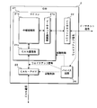
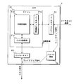
- the GW 2 includes a microcomputer 21, an Ethernet PHY (PHYsical layer) 22, a CAN-PHY 23, a bypass circuit 24, and the like.
- the microcomputer 21, Ethernet PHY22, CAN-PHY23, and bypass circuit 24 are mounted on the circuit board of the GW2 as individual ICs (Integrated Circuits), but the present invention is not limited to this. ..
- any or all of the microcomputer 21, Ethernet PHY22, CAN-PHY23, and bypass circuit 24 may be mounted on the circuit board of the GW2 as one IC.
- Each functional block of the microcomputer 21, Ethernet PHY 22, CAN-PHY 23, and bypass circuit 24 may be a circuit composed of a plurality of electric components mounted on a circuit board.
- the microcomputer 21 has a processor such as a CPU (Central Processing Unit) or an MPU (Micro-Processing Unit), a ROM (Read Only Memory), a RAM (Random Access Memory), and the like, and executes a program stored in the ROM. Performs various arithmetic processes. In the present embodiment, the microcomputer 21 performs a process of relaying communication between communication lines. In FIG. 2, the relay processing unit 21a is shown as a software-like functional unit that performs relay processing by the microcomputer 21.
- the microcomputer 21 has an Ethernet communication unit 21b that performs communication processing according to the Ethernet communication protocol, and a CAN communication unit 21c that performs communication processing according to the CAN communication protocol.
- the Ethernet communication unit 21b When the Ethernet communication unit 21b receives a message according to the Ethernet communication protocol, the Ethernet communication unit 21b acquires the data included in this message and gives it to the relay processing unit 21a. When data to be transmitted from the relay processing unit 21a to another device is given, the Ethernet communication unit 21b transmits this data as a message according to the Ethernet communication protocol.
- the CAN communication unit 21c when the CAN communication unit 21c receives a message according to the CAN communication protocol, the CAN communication unit 21c acquires the data included in this message and gives it to the relay processing unit 21a. When the relay processing unit 21a gives data to be transmitted to another device, the CAN communication unit 21c transmits this data as a message according to the CAN communication protocol.
- the microcomputer 21 can switch between the sleep state and the wake-up state.
- the microcomputer 21 performs the above-mentioned relay processing of the relay processing unit 21a, the communication processing of the Ethernet communication unit 21b, the communication processing of the CAN communication unit 21c, and the like.
- the microcomputer 21 does not perform these processes, for example, stops the oscillation of the clock signal for operation to reduce the power consumption.
- the microcomputer 21 determines a condition such as the engine of the vehicle 100 being stopped or the ignition switch being switched to the off state, and makes a transition from the wake-up state to the sleep state. The transition from the sleep state to the wake-up state of the microcomputer 21 is performed by the start control signal from the bypass circuit 24.
- the Ethernet PHY 22 is an IC that converts an analog electric signal on a communication line and a digital signal handled by the microcomputer 21.
- the Ethernet PHY 22 samples and acquires the potential of the Ethernet communication line connected to the GW 2, and outputs it as a digital signal to the microcomputer 21.
- the Ethernet PHY 22 converts the message given by the microcomputer 21 into an electric signal and outputs the message to the Ethernet communication line.
- the Ethernet PHY 22 can switch between the sleep state and the wake-up state. In the wake-up state, the Ethernet PHY 22 performs the above-mentioned conversion processing between the analog signal and the digital signal.
- the Ethernet PHY 22 performs a process of giving an analog signal on the communication line to the microcomputer 21 as a digital signal, but does not output the analog signal to the communication line. Switching between the sleep state and the wake-up state of the Ethernet PHY 22 is performed by a start control signal from the bypass circuit 24.
- the CAN-PHY 23 is an IC that converts an analog electric signal on a communication line and a digital signal handled by the microcomputer 21.
- the CAN-PHY 23 samples and acquires the potential of the CAN communication line connected to the GW 2, and outputs it as a digital signal to the microcomputer 21.
- the CAN-PHY 23 converts the message given by the microcomputer 21 into an electric signal and outputs the message to the CAN communication line.
- the CAN-PHY 23 can switch between the sleep state and the wake-up state. In the wake-up state, the CAN-PHY 23 performs the above-mentioned conversion processing between the analog signal and the digital signal.
- the CAN-PHY 23 performs a process of giving an analog signal on the communication line to the microcomputer 21 as a digital signal, but does not output the analog signal to the communication line. Switching between the sleep state and the wake-up state of the CAN-PHY 23 is performed by a start control signal from the bypass circuit 24.
- the bypass circuit 24 performs a process of bypassing and relaying the wakeup signal when the microcomputer 21 is in the sleep state.
- a wake-up signal (wake-up signal according to the Ethernet communication protocol) is received via the Ethernet communication line
- the bypass circuit 24 wakes up to the CAN communication line (wake-up signal according to the CAN communication protocol).
- the signal for outputting (up signal) is indicated by a broken arrow.
- FIG. 3 when a wakeup signal (wakeup signal according to the CAN communication protocol) is received via the CAN communication line, the bypass circuit 24 wakes up to the Ethernet communication line (wake according to the Ethernet communication protocol).
- the signal when the (up signal) is output is indicated by the broken arrow.
- the bypass circuit 24 monitors the Ethernet communication line when the microcomputer 21 is in the sleep state. When the bypass circuit 24 detects a wake-up signal on the Ethernet communication line, it activates CAN-PHY23 and gives a wake-up signal to output the wake-up signal to the CAN communication line. At this time, the bypass circuit 24 activates the microcomputer 21.
- the bypass circuit 24 monitors the communication line of the CAN when the microcomputer 21 is in the sleep state. When the bypass circuit 24 detects a wake-up signal on the CAN communication line, it activates the Ethernet PHY 22 and gives the wake-up signal to output the wake-up signal to the Ethernet communication line. At this time, the bypass circuit 24 activates the microcomputer 21.
- the bypass circuit 24 may always operate without switching between the sleep state and the wake-up state, and may have a configuration capable of switching between the sleep state and the wake-up state. In any case, the bypass circuit 24 is given a signal or the like indicating whether the microcomputer 21 is in the sleep state or the wake-up state from the microcomputer 21. When switching the state, the bypass circuit 24 transitions to the sleep state when the microcomputer 21 transitions to the wake-up state, and transitions to the wake-up state when the microcomputer 21 transitions to the sleep state.
- Ethernet wake-up signal for example, a signal based on the Ethernet Wake-on-LAN technology can be adopted.
- Wake-on-LAN a desired device can be activated by sending a message containing a specific pattern of data called a magic packet.
- a wake-up signal of the CAN for example, a dominant signal output for a predetermined time may be adopted.
- the bypass circuit 24 receives a magic packet message on the Ethernet communication line, it outputs a dominant for a predetermined time from the CAN communication line.
- the bypass circuit 24 detects a dominant for a predetermined time on the CAN communication line, the bypass circuit 24 transmits a message including a magic packet from the Ethernet communication line.
- the wake-up signal may have any configuration.
- the bypass circuit 24 has a function of retransmitting the wakeup signal.
- the bypass circuit 24 transmits a wake-up signal to the Ethernet communication line or the CAN communication line, and then determines the presence or absence of a response signal transmitted from a device (device such as ECU3 or GW1) connected to the communication line. judge.
- a device device such as ECU3 or GW1 connected to the communication line. judge.
- the bypass circuit 24 retransmits the wakeup signal to this communication line.
- a dominant signal output for a predetermined time can be adopted as the response signal to the wakeup signal.
- the bypass circuit 24 is in the dominant signal state of the communication line after finishing its own dominant output. By detecting the presence, it can be determined that the response signal has been output.
- a message containing a specific pattern of data can be adopted as a response signal.
- the response signal may have any configuration.
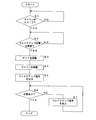
- FIG. 4 is a flowchart showing a procedure of bypass processing performed by the bypass circuit 24 according to the present embodiment.
- the bypass circuit 24 determines whether or not the microcomputer 21 is in the sleep state (step S1). When the microcomputer 21 is not in the sleep state (S1: NO), the bypass circuit 24 waits until the microcomputer 21 transitions to the sleep state.
- the bypass circuit 24 determines whether or not a wakeup signal has been received via the Ethernet communication line (step S2). When the wake-up signal is not received (S2: NO), the bypass circuit 24 waits until the wake-up signal is received. When the wakeup signal is received (S2: YES), the bypass circuit 24 outputs a start control signal for activating CAN-PHY23 (step S3). The bypass circuit 24 outputs a start control signal for starting the microcomputer 21 (step S4).
- the bypass circuit 24 outputs the wakeup signal to the CAN communication line by giving the wakeup signal according to the CAN communication protocol to the CAN-PHY23 (step S5). At this time, the bypass circuit 24 outputs the wake-up signal without waiting for the completion of switching from the sleep state to the wake-up state of the microcomputer 21.
- the bypass circuit 24 determines whether or not the response signal from the device connected to the communication line of the CAN that outputs the wakeup signal has been received by the elapse of a predetermined time (step). S6). If the response signal has not been received even after the lapse of the predetermined time (S7: NO), the bypass circuit 24 outputs a wakeup signal to this communication line (step S7), and returns the process to step S6. When the response signal is received by the elapse of the predetermined time (S6: YES), the bypass circuit 24 ends the bypass processing of the wakeup signal.
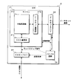
- FIG. 5 is a block diagram showing the configuration of GW2 according to the second embodiment.
- the bypass circuit 24 does not directly acquire the wake-up signal from the Ethernet communication line, but the Ethernet PHY 22 acquires the wake-up signal converted into a digital signal.
- the bypass circuit 24 according to the second embodiment does not acquire the wakeup signal directly from the communication line of the CAN, but acquires the wakeup signal converted into a digital signal by the CAN-PHY23.
- the configuration of the bypass circuit 24 according to the second embodiment is the same as the configuration of the bypass circuit 24 according to the first embodiment.
- the bypass circuit 24 needs to include a conversion circuit from an analog signal to a digital signal in the bypass circuit 24 by acquiring a wakeup signal converted into a digital signal by the Ethernet PHY 22 and CAN-PHY 23. Therefore, the bypass circuit 24 can be expected to be downsized.
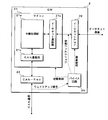
- FIG. 6 is a block diagram showing the configuration of GW2 according to the third embodiment.
- the GW 2 according to the third embodiment does not output the wake-up signal to the CAN-PHY23, but directly outputs the wake-up signal to the communication line of the CAN.
- the bypass circuit 24 according to the third embodiment does not output the wakeup signal to the Ethernet PHY 22, but outputs the wakeup signal directly to the Ethernet communication line. Since the bypass circuit 24 according to the third embodiment outputs the wakeup signal directly to the CAN communication line or the Ethernet communication line, it is necessary to activate the CAN-PHY23 or the Ethernet PHY22 before outputting the wakeup signal. Absent.
- the bypass circuit 24 according to the third embodiment may be configured not to output the activation control signals of the CAN-PHY 23 and the Ethernet PHY 22.
- the bypass circuit 24 according to the third embodiment outputs a wakeup signal as an analog signal.
- the configuration of the bypass circuit 24 according to the third embodiment is the same as the configuration of the bypass circuit 24 according to the first embodiment.
- bypass circuit 24 can directly bypass and relay the wakeup signal between the Ethernet communication line and the CAN communication line, the wakeup signal is relayed more quickly. Can be expected.
- FIG. 7 is a block diagram showing the configuration of GW2 according to the fourth embodiment.
- the bypass circuit 24 does not acquire the wake-up signal from the Ethernet communication line, but acquires the wake-up signal from the Ethernet PHY 22. Therefore, the Ethernet PHY 22 according to the seventh embodiment has a function of outputting a signal for notifying the wakeup signal to the bypass circuit 24 when the wakeup signal is detected on the Ethernet communication line.
- This signal output by Ethernet PHY2 may be input to the microcomputer 21 as a start-up signal.
- the bypass circuit 24 activates the CAN-PHY23 to output the wakeup signal, and outputs the wakeup signal to the communication line of the CAN.
- the CAN-PHY23 has a function of outputting a signal for notifying the wakeup signal to the bypass circuit 24 when a wakeup signal is detected on the communication line of the CAN. ..
- This signal output by the CAN-PHY 23 may be input to the microcomputer 21 as a start signal.
- the bypass circuit 24 activates the Ethernet PHY 22 to output the wake-up signal, and outputs the wake-up signal to the Ethernet communication line.
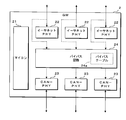
- FIG. 8 is a block diagram showing the configuration of GW2 according to the fifth embodiment.
- the GW 2 according to the fifth embodiment includes a plurality of Ethernet PHY 22 and a plurality of CAN-PHY 23, and the relay processing unit 21a of the microcomputer 21 is located between the plurality of Ethernet communication lines and the plurality of CAN communication lines. Relay the message with. At this time, the relay processing unit 21a determines the relay destination of the message based on the ID attached to the message and the like.
- the microcomputer 21 stores in advance a routing table or the like in which the ID and the relay destination are associated with each other in the ROM. Note that in FIG. 8, the route of message relay by the microcomputer 21 is not shown.
- the bypass circuit 24 of the GW 2 monitors the presence or absence of a wake-up signal for each Ethernet communication line.
- the bypass circuit 24 detects a wakeup signal on any of the Ethernet communication lines, the bypass circuit 24 outputs the wakeup signal to one or more CAN-PHY 23s, thereby transmitting the wakeup signal to the communication of one or more CANs. Bypass to the line and relay.
- the bypass circuit 24 may transmit the wakeup signal to the Ethernet communication line other than the Ethernet communication line that received the wakeup signal.
- the bypass circuit 24 has a bypass table 24a for determining a relay destination for bypassing and relaying the wakeup signal.
- the bypass circuit 24 has a non-volatile memory element such as an EEPROM (Electrically Erasable Programmable Read Only Memory), and stores the bypass table 24a in this memory element.
- EEPROM Electrically Erasable Programmable Read Only Memory
- the wake-up signal of the Ethernet communication protocol transmitted / received in the in-vehicle communication system includes, for example, an ID of the source ECU 3, an ID of the destination ECU 3, or an ID indicating the type of the wake-up signal. Identification information such as is attached.
- the GW1 and GW2 and the like include the identification information in the magic packet and transmit the message.
- the bypass circuit 24 refers to the bypass table 24a based on the identification information associated with the wakeup signal received on any of the Ethernet communication lines, and the communication line of the destination CAN set in the bypass table 24a (the bypass circuit 24). And the Ethernet communication line) to send a wakeup signal.
- the bypass circuit 24 monitors the presence or absence of a wakeup signal for each CAN communication line.
- the bypass circuit 24 detects a wakeup signal on one of the CAN communication lines, it outputs the wakeup signal to one or more Ethernet PHY22s to output the wakeup signal to one or more Ethernet communication lines.
- the bypass circuit 24 may transmit the wakeup signal to the communication line of the CAN other than the communication line of the CAN that has received the wakeup signal.
- the wake-up signal of the CAN communication protocol transmitted and received in the in-vehicle communication system includes, for example, an ID of the source ECU 3, an ID of the transmission destination ECU 3, or an ID indicating the type of the wake-up signal. Identification information such as is attached.
- the GW2, ECU3, etc. transmit the dominant signal for the predetermined time, and then transmit identification information following the dominant signal. ..
- the bypass circuit 24 receives the dominant signal for a predetermined time on the CAN communication line, and then receives the identification information following the dominant signal.
- the bypass circuit 24 refers to the bypass table 24a based on the received identification information, and transmits a wakeup signal to the transmission destination Ethernet communication line (and CAN communication line) set in the bypass table 24a. ..
- GW2 In GW2 according to the fifth embodiment, a plurality of Ethernet communication lines and a plurality of CAN communication lines are connected, and a message is relayed between the plurality of communication lines.
- the bypass circuit 24 of the GW 2 according to the fifth embodiment bypasses the wake-up signal received on one of the communication lines and transmits the wake-up signal to the other communication line. At this time, the bypass circuit 24 determines the communication line for transmitting the wakeup signal by referring to the preset bypass table 24a based on the identification information accompanying the wakeup signal.
- FIG. 8 shows a configuration in which three Ethernet communication lines are connected to the GW2 and three CAN communication lines are connected, but the number of communication lines is an example and is limited to this. is not it.
- the start signal from the bypass circuit 24 to the microcomputer 21 and the start signal from the bypass circuit 24 to the Ethernet PHY 22 and the CAN-PHY 23 are not shown.
- the bypass circuit 24 according to the fifth embodiment may determine whether or not to activate the microcomputer 21 based on, for example, the identification information accompanying the wakeup signal. In this case, information indicating whether or not to start the microcomputer 21 is stored in the bypass table 24a in association with the identification information of the wakeup signal.
- the GW2 transmits / receives a message between an Ethernet communication line that communicates according to the Ethernet communication protocol and a CAN communication line that communicates according to the CAN communication protocol. Relay.
- the bypass circuit 24 of the GW2 transmits the wakeup signal of the CAN communication protocol to the CAN. Output to the communication line.
- the bypass circuit 24 outputs the wake-up signal of the CAN communication protocol to the CAN communication line to the CAN communication line even if the microcomputer 21 does not transition from the sleep state to the wake-up state or before the transition. Since the connected device can be activated, it can be expected that the wakeup signal is relayed at high speed.
- the bypass circuit 24 outputs a control signal for activating the microcomputer 21 from the sleep state to the wake-up state.
- the microcomputer 21 may be activated in response to the control signal from the bypass circuit 24, so that it may not be necessary to monitor the presence or absence of the wakeup signal on the communication line in the sleep state.
- the microcomputer 21 does not start in response to the wake-up signal directly received via the communication line, but starts in response to the signal from the bypass circuit 24. As a result, the microcomputer 21 is not activated in response to the wake-up signal, and can be activated only when the bypass circuit 24 determines that it is necessary.
- the GW 2 is a bypass circuit when a response from the ECU 3 or the like connected to the CAN communication line is not received after outputting the wake-up signal of the CAN communication protocol to the CAN communication line. 24 retransmits the wakeup signal. As a result, even if the activation of the ECU 3 or the like in response to the wake-up signal fails for some reason, the bypass circuit 24 retransmits the wake-up signal to increase the possibility that the desired device is activated. Can be done.
- a plurality of CAN communication lines are connected.
- the GW2 bypass circuit 24 receives a wakeup signal from the Ethernet communication line, the GW2 bypass circuit 24 does not output the wakeup signal to all CAN communication lines, but instead outputs the wakeup signal to the wakeup signal received by the Ethernet communication line.
- the CAN communication line that outputs the wakeup signal of the CAN communication protocol is selected. As a result, it is possible to avoid starting unnecessary devices.
- the GW 2 includes a CAN-PHY 23 that converts an analog signal and a digital signal between the communication lines of the microcomputer 21 and the CAN.
- the bypass circuit 24 of the GW 2 outputs a signal for controlling the activation of the CAN-PHY 23. As a result, the power consumption of CAN-PHY23 of GW2 can be reduced.
- the bypass circuit 24 when the wakeup signal of the CAN communication protocol is received from the communication line of the CAN, the bypass circuit 24 outputs the wakeup signal of the Ethernet communication protocol to the Ethernet communication line. As a result, the bypass circuit 24 can bypass and relay the wake-up signal in both directions of the Ethernet communication line and the CAN communication line.
- Ethernet and CAN are mentioned as communication protocols used in the in-vehicle communication system, but the present invention is not limited to this, and various communication protocols other than Ethernet and CAN may be adopted. Further, in the GW2, communication lines of three or more different communication protocols may be connected, and in this case as well, when the bypass circuit 24 receives a wakeup signal of one communication protocol, the other two communication protocols Wake-up signals may be output to each communication line.
- bypass circuit 24 of the GW 2 bypasses the wake-up signal and relays in both directions from the Ethernet communication line to the CAN communication line and from the CAN communication line to the Ethernet communication line.
- the bypass circuit 24 bypasses and relays the wake-up signal from either the Ethernet communication line to the CAN communication line or from the CAN communication line to the Ethernet communication line, and the microcomputer 21 wakes the other.
- the up signal may be relayed.
- the GW1 may also be configured to bypass and relay the wakeup signal by providing the bypass circuit 24 in the same manner. Since the GW1 shown in FIG. 1 has a configuration in which only Ethernet communication lines are connected, the bypass circuit 24 directly physically or electrically connects a plurality of communication lines using circuit elements such as switches or relays. Therefore, the wake-up signal may be bypassed and relayed.
- Each device in the in-vehicle communication system includes a computer including a microprocessor, ROM, RAM, and the like.
- An arithmetic processing unit such as a microprocessor may read a computer program including a part or all of each step of a sequence diagram or a flowchart as shown in FIG. 4 from a storage unit such as a ROM or a RAM and execute the program.
- the computer programs of these plurality of devices can be installed from an external server device or the like. Further, the computer programs of these plurality of devices are distributed in a state of being stored in a recording medium such as a CD-ROM, a DVD-ROM, or a semiconductor memory, respectively.
Abstract
Provided are an onboard relay device and a relay method with which the high-speed relay of a startup signal can be expected between communication lines employing different communication protocols. An onboard relay device according to the present embodiment in which a first communication line for performing communication according to a first communication protocol and a second communication line for performing communication according to a second communication protocol are connected, and in which communications are relayed between the first communication line and the second communication line. The onboard relay device is provided with: a processing unit that can switch between a sleep state and a non-sleep state and that, in the non-sleep state, performs the process of relaying communications between the first communication line and the second communication line; and a startup signal output unit that, when the processing unit is in the sleep state and receives a startup signal of the first communication protocol from the first communication line, outputs a startup signal of the second communication protocol to the second communication line.
Description
本開示は、第1通信線及び第2通信線の間の通信を中継する車載中継装置及び中継方法に関する。
The present disclosure relates to an in-vehicle relay device and a relay method for relaying communication between a first communication line and a second communication line.
従来、車両に搭載されたECU(Electronic Control Unit)及びゲートウェイ等の装置では、例えば車両のエンジンが停止状態である等の状況で処理を行う必要がない場合に、消費電力を低減するスリープ状態(スタンバイ状態又は待機状態等)へ移行する制御が行われている。スリープ状態の装置は、例えば通信により起動信号(ウェイクアップ信号等)を受信した場合に、スリープ状態から非スリープ状態(ウェイクアップ状態又はアクティブ状態等)へ移行し、処理を開始する。
Conventionally, devices such as an ECU (Electronic Control Unit) and a gateway mounted on a vehicle have a sleep state (a sleep state) that reduces power consumption when it is not necessary to perform processing in a situation such as when the vehicle engine is stopped. Control to shift to the standby state or the standby state, etc. is performed. When the device in the sleep state receives an activation signal (wake-up signal, etc.) by communication, for example, it shifts from the sleep state to the non-sleep state (wake-up state, active state, etc.) and starts processing.
特許文献1においては、2つのネットワークの接続先をバイパス用のバス又はコントローラのいずれかに切り替える切替回路を用いて、スリープ状態の場合には2つのネットワークをバイパス用のバスに接続し、ウェイクアップ状態の場合には2つのネットワークをコントローラに接続する車載ゲートウェイ装置が提案されている。
In Patent Document 1, a switching circuit that switches the connection destination of the two networks to either the bypass bus or the controller is used, and in the sleep state, the two networks are connected to the bypass bus and wake up. In the case of a state, an in-vehicle gateway device that connects two networks to a controller has been proposed.
近年、車両に搭載される装置の数は増大し、車両内のネットワークは巨大化及び複雑化している。このため、一の装置から他の装置への通信経路には複数のゲートウェイが介在する可能性がある。例えば、一の装置が起動信号を送信した場合、この起動信号が途中のゲートウェイを順に起動し、ゲートウェイが起動信号を順に中継し、最終的に他の装置が起動信号を受信して起動する。このため、一の装置が起動信号を送信してから他の装置が処理を開始するまでに長い時間を要するという問題がある。特許文献1に記載の車載ゲートウェイ装置は、スリープ状態の場合に2つのネットワークを直結することで信号を直接的に中継することができるが、この装置構成は2つのネットワークが異なる通信プロトコルを採用したものである場合には採用することができないという問題がある。
In recent years, the number of devices mounted on vehicles has increased, and the network inside the vehicle has become huge and complicated. Therefore, there is a possibility that a plurality of gateways intervene in the communication path from one device to another device. For example, when one device transmits a start signal, this start signal activates the gateways in the middle in order, the gateway relays the start signals in order, and finally the other device receives the start signal and starts. Therefore, there is a problem that it takes a long time from one device transmitting the start signal to the other device starting the process. The in-vehicle gateway device described in Patent Document 1 can directly relay a signal by directly connecting two networks in a sleep state, but this device configuration adopts a communication protocol in which the two networks are different. There is a problem that it cannot be adopted if it is a thing.
本開示は、斯かる事情に鑑みてなされたものであって、その目的とするところは、異なる通信プロトコルが採用された通信線間で起動信号を高速に中継することが期待できる車載中継装置及び中継方法を提供することにある。
The present disclosure has been made in view of such circumstances, and an object thereof is an in-vehicle relay device that can be expected to relay a start signal at high speed between communication lines adopting different communication protocols. The purpose is to provide a relay method.
本態様に係る車載中継装置は、第1通信プロトコルに応じた通信を行う第1通信線、及び、第2通信プロトコルに応じた通信を行う第2通信線が接続され、前記第1通信線及び前記第2通信線の間の通信を中継する車載中継装置であって、スリープ状態及び非スリープ状態に切り替え可能であり、前記非スリープ状態である場合に前記第1通信線及び前記第2通信線の間の通信を中継する処理を行う処理部と、前記処理部がスリープ状態であり、且つ、前記第1通信線から前記第1通信プロトコルの起動信号を受信した場合に、前記第2通信プロトコルの起動信号を前記第2通信線へ出力する起動信号出力部とを備える。
In the vehicle-mounted relay device according to this embodiment, a first communication line for communication according to the first communication protocol and a second communication line for communication according to the second communication protocol are connected, and the first communication line and the first communication line and the second communication line for communication according to the second communication protocol are connected. An in-vehicle relay device that relays communication between the second communication lines, which can be switched between a sleep state and a non-sleep state, and when the non-sleep state is in the non-sleep state, the first communication line and the second communication line. The second communication protocol when the processing unit that performs the process of relaying the communication between the two is in the sleep state and the activation signal of the first communication protocol is received from the first communication line. It is provided with a start signal output unit that outputs the start signal of the above to the second communication line.
本願は、このような特徴的な処理部を備える車載中継装置等の装置として実現することができるだけでなく、かかる特徴的な処理をステップとする中継方法として実現したり、かかるステップをコンピュータに実行させるためのコンピュータプログラムとして実現したりすることができる。これらの装置の一部又は全部を実現する半導体集積回路として実現したり、これらの装置を含むその他の装置又はシステムとして実現したりすることができる。
The present application can be realized not only as a device such as an in-vehicle relay device provided with such a characteristic processing unit, but also as a relay method in which the characteristic processing is a step, or the step is executed on a computer. It can be realized as a computer program for making it. It can be realized as a semiconductor integrated circuit that realizes a part or all of these devices, or can be realized as another device or system including these devices.
上記によれば、異なる通信プロトコルが採用された通信線間で起動信号を高速に中継することが期待できる。
According to the above, it can be expected that the start signal is relayed at high speed between communication lines that employ different communication protocols.
[本開示の実施の形態の説明]
最初に本開示の実施態様を列記して説明する。以下に記載する実施形態の少なくとも一部を任意に組み合わせてもよい。 [Explanation of Embodiments of the present disclosure]
First, embodiments of the present disclosure will be listed and described. At least a part of the embodiments described below may be arbitrarily combined.
最初に本開示の実施態様を列記して説明する。以下に記載する実施形態の少なくとも一部を任意に組み合わせてもよい。 [Explanation of Embodiments of the present disclosure]
First, embodiments of the present disclosure will be listed and described. At least a part of the embodiments described below may be arbitrarily combined.
(1)本態様に係る車載情報処理装置は、第1通信プロトコルに応じた通信を行う第1通信線、及び、第2通信プロトコルに応じた通信を行う第2通信線が接続され、前記第1通信線及び前記第2通信線の間の通信を中継する車載中継装置であって、スリープ状態及び非スリープ状態に切り替え可能であり、前記非スリープ状態である場合に前記第1通信線及び前記第2通信線の間の通信を中継する処理を行う処理部と、前記処理部がスリープ状態であり、且つ、前記第1通信線から前記第1通信プロトコルの起動信号を受信した場合に、前記第2通信プロトコルの起動信号を前記第2通信線へ出力する起動信号出力部とを備える。
(1) The in-vehicle information processing apparatus according to this embodiment is connected to a first communication line for communication according to the first communication protocol and a second communication line for communication according to the second communication protocol. An in-vehicle relay device that relays communication between one communication line and the second communication line, and can be switched between a sleep state and a non-sleep state. In the non-sleep state, the first communication line and the second communication line and the above. When the processing unit that performs the process of relaying the communication between the second communication lines and the processing unit are in the sleep state and receive the activation signal of the first communication protocol from the first communication line, the said It includes an activation signal output unit that outputs an activation signal of the second communication protocol to the second communication line.
本態様にあっては、第1通信プロトコルに応じた通信を行う第1通信線と、第2通信プロトコルに応じた通信を行う第2通信線との間の通信を車載中継装置が中継する。中継処理を行う処理部がスリープ状態であり、第1通信線から第1通信プロトコルの起動信号を受信した場合、車載中継装置の起動信号出力部が、第2通信プロトコルの起動信号を第2通信線へ出力する。これにより、処理部がスリープ状態から非スリープ状態へ移行しなくても又は移行する前に、起動信号出力部が第2通信プロトコルの起動信号を第2通信線へ出力し、第2通信線に接続された装置を起動することができるため、起動信号を高速に中継することが期待できる。
In this embodiment, the in-vehicle relay device relays the communication between the first communication line that performs communication according to the first communication protocol and the second communication line that performs communication according to the second communication protocol. When the processing unit that performs relay processing is in the sleep state and receives the activation signal of the first communication protocol from the first communication line, the activation signal output unit of the in-vehicle relay device transmits the activation signal of the second communication protocol to the second communication. Output to the line. As a result, the activation signal output unit outputs the activation signal of the second communication protocol to the second communication line to the second communication line even if the processing unit does not shift from the sleep state to the non-sleep state or before the transition. Since the connected device can be activated, it can be expected that the activation signal will be relayed at high speed.
(2)前記起動信号出力部は、前記処理部の起動を制御する制御信号を出力することが好ましい。
(2) It is preferable that the start signal output unit outputs a control signal for controlling the start of the processing unit.
本態様にあっては、起動信号出力部が処理部の起動を制御する制御信号を出力する。これにより処理部は、起動信号出力部からの制御信号に応じて起動すればよいため、スリープ状態において通信線上の起動信号の有無を監視する必要がなくなる可能性がある。
In this embodiment, the start signal output unit outputs a control signal that controls the start of the processing unit. As a result, the processing unit may be activated in response to the control signal from the activation signal output unit, so that it may not be necessary to monitor the presence or absence of the activation signal on the communication line in the sleep state.
(3)前記処理部は、前記起動信号に応じて起動せず、前記制御信号に応じて起動することが好ましい。
(3) It is preferable that the processing unit is not activated in response to the activation signal, but is activated in response to the control signal.
本態様にあっては、処理部は通信線を介して受信する起動信号に応じて起動せず、起動信号出力部からの制御信号に応じて起動する。これにより、処理部を起動信号に応じて起動させず、起動信号出力部が必要と判断した場合にのみ起動させることができる。
In this embodiment, the processing unit does not start in response to the start signal received via the communication line, but starts in response to the control signal from the start signal output unit. As a result, the processing unit is not activated in response to the activation signal, and can be activated only when the activation signal output unit determines that it is necessary.
(4)前記起動信号出力部は、前記第2通信プロトコルの起動信号を前記第2通信線へ出力した後、前記第2通信線に接続された装置からの応答を受信しない場合に、前記第2通信プロトコルの起動信号を再出力することが好ましい。
(4) When the activation signal output unit does not receive a response from the device connected to the second communication line after outputting the activation signal of the second communication protocol to the second communication line, the first operation signal output unit. 2 It is preferable to re-output the activation signal of the communication protocol.
本態様にあっては、第2通信プロトコルの起動信号を第2通信へ出力した後に、第2通信線に接続された装置からの応答を受信しない場合には、起動信号出力部が起動信号の再送信を行う。これにより、何らかの理由で起動に失敗した場合であっても、起動信号出力部が起動信号を再送信することにより所望の装置が起動する可能性を高めることができる。
In this embodiment, if a response from the device connected to the second communication line is not received after outputting the activation signal of the second communication protocol to the second communication, the activation signal output unit is the activation signal. Retransmit. Thereby, even if the start-up fails for some reason, the possibility that the desired device is started up by the start-up signal output unit retransmitting the start-up signal can be increased.
(5)前記第2通信線が複数接続されており、前記起動信号出力部は、前記第1通信線から受信した前記第1通信プロトコルの起動信号に付随する情報に基づいて、前記第2通信プロトコルの起動信号をいずれの前記第2通信線へ出力するかを選択することが好ましい。
(5) A plurality of the second communication lines are connected, and the activation signal output unit performs the second communication based on the information accompanying the activation signal of the first communication protocol received from the first communication line. It is preferable to select which of the second communication lines the protocol activation signal is output to.
本態様にあっては、車載中継装置に複数の第2通信線が接続される。第1通信線から第1通信プロトコルの起動信号を受信した場合に、起動信号出力部は、全ての第2通信線へ第2通信プロトコルの起動信号を出力するのではなく、第1通信プロトコルの起動信号に付随する情報に基づいて第2通信プロトコルの起動信号を出力する第2通信線を選択する。これにより、不要な装置の起動を避けることができる。
In this embodiment, a plurality of second communication lines are connected to the in-vehicle relay device. When the activation signal of the first communication protocol is received from the first communication line, the activation signal output unit does not output the activation signal of the second communication protocol to all the second communication lines, but of the first communication protocol. The second communication line that outputs the activation signal of the second communication protocol is selected based on the information accompanying the activation signal. As a result, it is possible to avoid starting unnecessary devices.
(6)前記第2通信線及び前記処理部の間に介在し、スリープ状態及び非スリープ状態に切り替え可能であり、前記非スリープ状態である場合に前記第2通信線を介して送受信されるアナログ信号と前記処理部へ入出力されるデジタル信号とを変換する変換部を備え、前記起動信号出力部は、前記変換部の起動を制御する制御信号を出力することが好ましい。
(6) An analog that is interposed between the second communication line and the processing unit, can be switched between a sleep state and a non-sleep state, and is transmitted and received via the second communication line in the non-sleep state. It is preferable to include a conversion unit that converts a signal and a digital signal input / output to the processing unit, and the activation signal output unit outputs a control signal that controls activation of the conversion unit.
本態様にあっては、車載中継装置は、処理部及び第2通信線の間にアナログ信号とデジタル信号との変換を行う変換部を備え、変換部はスリープ状態及び非スリープ状態の切り替えが可能である。起動信号出力部は、この変換部の起動を制御する制御信号を出力する。これにより、車載中継装置の変換部の電力消費量の低減を図ることができる。
In this embodiment, the in-vehicle relay device includes a conversion unit that converts an analog signal and a digital signal between the processing unit and the second communication line, and the conversion unit can switch between a sleep state and a non-sleep state. Is. The start-up signal output unit outputs a control signal that controls the start-up of this conversion unit. As a result, it is possible to reduce the power consumption of the conversion unit of the in-vehicle relay device.
(7)前記起動信号出力部は、前記第2通信線から前記第2通信プロトコルの起動信号を受信した場合に、前記第1通信プロトコルの起動信号を前記第1通信線へ出力することが好ましい。
(7) When the activation signal output unit receives the activation signal of the second communication protocol from the second communication line, it is preferable that the activation signal output unit outputs the activation signal of the first communication protocol to the first communication line. ..
本態様にあっては、第2通信線から第2通信プロトコルの起動信号を受信した場合に、起動信号出力部が第1通信プロトコルの起動信号を第1通信線へ出力する。これにより起動信号出力部は、第1通信線及び第2通信線の双方向について起動信号を中継することができる。
In this embodiment, when the activation signal of the second communication protocol is received from the second communication line, the activation signal output unit outputs the activation signal of the first communication protocol to the first communication line. As a result, the start-up signal output unit can relay the start-up signal in both directions of the first communication line and the second communication line.
(8)本態様に係る中継方法は、第1通信プロトコルに応じた通信を行う第1通信線、及び、第2通信プロトコルに応じた通信を行う第2通信線が接続され、前記第1通信線及び前記第2通信線の間の通信を中継する処理を行う処理部を有する車載中継装置が、前記処理部が非スリープ状態である場合に、前記処理部が前記第1通信線及び前記第2通信線の間の通信を中継する処理を行い、前記処理部がスリープ状態であり、且つ、前記第1通信線から前記第1通信プロトコルの起動信号を受信した場合に、前記第2通信プロトコルの起動信号を前記第2通信線へ出力する。
(8) In the relay method according to this aspect, the first communication line that performs communication according to the first communication protocol and the second communication line that performs communication according to the second communication protocol are connected, and the first communication is described. When an in-vehicle relay device having a processing unit that performs a process of relaying communication between a line and the second communication line is in a non-sleep state, the processing unit performs the first communication line and the first communication line. The second communication protocol is performed when the processing for relaying the communication between the two communication lines is performed, the processing unit is in the sleep state, and the activation signal of the first communication protocol is received from the first communication line. Is output to the second communication line.
本態様にあっては、態様(1)と同様に、起動信号を高速に中継することが期待できる。
In this aspect, it can be expected that the activation signal is relayed at high speed as in the aspect (1).
[本開示の実施形態の詳細]
本開示の実施形態に係る車載中継装置の具体例を、以下に図面を参照しつつ説明する。本開示はこれらの例示に限定されるものではなく、請求の範囲によって示され、請求の範囲と均等の意味及び範囲内でのすべての変更が含まれることが意図される。 [Details of Embodiments of the present disclosure]
A specific example of the vehicle-mounted relay device according to the embodiment of the present disclosure will be described below with reference to the drawings. The present disclosure is not limited to these examples, but is indicated by the scope of claims and is intended to include all modifications within the meaning and scope equivalent to the scope of claims.
<システム概要>
図1は、本実施の形態に係る車載通信システムの一構成例を示す模式図である。本実施の形態に係る車載通信システムは、中央のGW(ゲートウェイ)1と、周辺の複数のGW2a~2dと、複数のECU3a~3dと、複数のセンサ4a~4dと、複数のアクチュエータ5a~5dとが車両100の適所に搭載された構成である。なお図1においては、車両100の前後左右の方向が、図の上下左右の方向に相当するものとしている。 <System overview>
FIG. 1 is a schematic diagram showing a configuration example of an in-vehicle communication system according to the present embodiment. The in-vehicle communication system according to the present embodiment includes a central GW (gateway) 1, a plurality of peripheral GWs 2a to 2d, a plurality ofECUs 3a to 3d, a plurality of sensors 4a to 4d, and a plurality of actuators 5a to 5d. Is a configuration in which the vehicle 100 is mounted in a suitable place. In FIG. 1, it is assumed that the front-rear, left-right directions of the vehicle 100 correspond to the up-down, left-right directions in the figure.
図1は、本実施の形態に係る車載通信システムの一構成例を示す模式図である。本実施の形態に係る車載通信システムは、中央のGW(ゲートウェイ)1と、周辺の複数のGW2a~2dと、複数のECU3a~3dと、複数のセンサ4a~4dと、複数のアクチュエータ5a~5dとが車両100の適所に搭載された構成である。なお図1においては、車両100の前後左右の方向が、図の上下左右の方向に相当するものとしている。 <System overview>
FIG. 1 is a schematic diagram showing a configuration example of an in-vehicle communication system according to the present embodiment. The in-vehicle communication system according to the present embodiment includes a central GW (gateway) 1, a plurality of peripheral GWs 2a to 2d, a plurality of
GW1は、車両100の中央に配置される中継装置である。本実施の形態に係る車載通信システムでは、GW1に4つのGW2a~2dがそれぞれ通信線を介して接続されている。本図において太い一点鎖線で示す矢印は、イーサネット(登録商標)の通信プロトコルに従う通信を行う通信線である。本実施の形態においてGW1及び4つのGW2a~2dは、イーサネットの通信プロトコルに従って通信を行う。GW1は、GW2a~2dのいずれかから受信したメッセージを、他のGW2a~2dへ送信することによって、GW2a~2dの間のメッセージ送受信を中継する処理を行う。
GW1 is a relay device arranged in the center of the vehicle 100. In the in-vehicle communication system according to the present embodiment, four GWs 2a to 2d are connected to the GW1 via communication lines. The arrow indicated by the thick alternate long and short dash line in this figure is a communication line that performs communication according to the Ethernet (registered trademark) communication protocol. In the present embodiment, the GW 1 and the four GWs 2a to 2d communicate according to the Ethernet communication protocol. The GW 1 performs a process of relaying message transmission / reception between the GWs 2a and 2d by transmitting a message received from any of the GWs 2a to 2d to the other GWs 2a to 2d.
GW2は、車両の周辺部分に配置される中継装置である。図示の例では、車両100の左前方にGW2aが配置され、右前方にGW2bが配置され、右後方にGW2cが配置され、左後方にGW2dが配置されている。各GW2a~2dには、近傍に配置されたECU3a~3dがそれぞれ接続される。なお図示の例では、各GW2a~2dにそれぞれ1つのECU3a~3dが接続されているが、GW2a~2dには複数のECU3a~3dが接続されてもよい。本図において実線で示す矢印は、CAN(Controller Area Network)の通信プロトコルに従う通信を行う通信線である。本実施の形態においてGW2a~2d及びECU3a~3dは、CANの通信プロトコルに従って通信を行う。GW2a~2dは、ECU3a~3dから受信したメッセージをGW1へ送信し、GW1から受信したメッセージをECU3a~3dへ送信することによって、GW1とECU3a~3dとの間のメッセージ送受信を中継する処理を行う。
GW2 is a relay device arranged in the peripheral part of the vehicle. In the illustrated example, the GW2a is arranged on the left front side of the vehicle 100, the GW2b is arranged on the right front side, the GW2c is arranged on the right rear side, and the GW2d is arranged on the left rear side. ECUs 3a to 3d arranged in the vicinity are connected to the GWs 2a to 2d, respectively. In the illustrated example, one ECU 3a to 3d is connected to each of the GWs 2a to 2d, but a plurality of ECUs 3a to 3d may be connected to the GWs 2a to 2d. The arrows shown by solid lines in this figure are communication lines that perform communication according to the communication protocol of CAN (Controller Area Network). In the present embodiment, the GWs 2a to 2d and the ECUs 3a to 3d communicate according to the CAN communication protocol. The GWs 2a to 2d transmit the messages received from the ECUs 3a to 3d to the GW1 and transmit the messages received from the GW1 to the ECUs 3a to 3d to relay the message transmission / reception between the GW1 and the ECUs 3a to 3d. ..
ただし本実施の形態においてGW2a~2dは、GW1との間でイーサネットの通信プロトコルに従う通信を行い、ECU3a~3dとの間でCANの通信プロトコルに従う通信を行う。このためGW2a~2dは、メッセージを中継する際に通信プロトコルの変換を行う。GW2a~2dは、ECU3a~3dから受信したCANの通信プロトコルに従うメッセージを、イーサネットの通信プロトコルに従うメッセージに変換してGW1へ送信する。GW2a~2dは、GW1から受信したイーサネットの通信プロトコルに従うメッセージを、CANの通信プロトコルに従うメッセージに変換してECU3a~3dへ送信する。
However, in the present embodiment, the GWs 2a to 2d perform communication with the GW1 according to the Ethernet communication protocol, and communicate with the ECUs 3a to 3d according to the CAN communication protocol. Therefore, the GWs 2a to 2d convert the communication protocol when relaying the message. The GWs 2a to 2d convert the message according to the CAN communication protocol received from the ECUs 3a to 3d into a message according to the Ethernet communication protocol and transmit it to the GW1. The GWs 2a to 2d convert the message according to the Ethernet communication protocol received from the GW1 into a message according to the CAN communication protocol and transmit the message to the ECUs 3a to 3d.
各ECU3a~3dには、情報を入力する入力装置としてセンサ4a~4dと、制御対象の装置としてアクチュエータ5a~5dとが接続されている。ただしECU3a~3dに接続される入力装置はセンサ4a~4dに限らず、例えばユーザが操作するスイッチ等の種々の装置であってよい。ECU3a~3dが接続される制御対象の装置はアクチュエータ5a~5dに限らず、例えばモータ又はライト等の種々の装置であってよい。ECU3a~3dには、センサ4a~4d及びアクチュエータ5a~5dの両方が接続されていなくてもよく、センサ4a~4d又はアクチュエータ5a~5dの一方のみが接続されていてもよい。
Sensors 4a to 4d are connected to each of the ECUs 3a to 3d as input devices for inputting information, and actuators 5a to 5d are connected as devices to be controlled. However, the input devices connected to the ECUs 3a to 3d are not limited to the sensors 4a to 4d, and may be various devices such as switches operated by the user, for example. The devices to be controlled to which the ECUs 3a to 3d are connected are not limited to the actuators 5a to 5d, and may be various devices such as a motor or a light. Both the sensors 4a to 4d and the actuators 5a to 5d may not be connected to the ECUs 3a to 3d, or only one of the sensors 4a to 4d or the actuators 5a to 5d may be connected.
例えばECU3a~3dは、センサ4a~4dが検知した種々の物理量に応じて、制御対象のアクチュエータ5a~5dの動作を制御する処理を行う。センサ4a~4dは、検知結果である物理量に応じたアナログ又はデジタルの電気信号を、信号線を介してECU3a~3dへ入力する。ECU3a~3dは、アクチュエータ5a~5dの制御量に応じたアナログ又はデジタルの電気信号を、信号線を介してアクチュエータ5a~5dへ入力する。本図において、ECU3a~3dとセンサ4a~4d及びアクチュエータ5a~5dとを接続する信号線は、破線の矢印として示されている。
For example, the ECUs 3a to 3d perform a process of controlling the operation of the actuators 5a to 5d to be controlled according to various physical quantities detected by the sensors 4a to 4d. The sensors 4a to 4d input analog or digital electric signals according to the physical quantity which is the detection result to the ECUs 3a to 3d via the signal line. The ECUs 3a to 3d input analog or digital electric signals according to the control amount of the actuators 5a to 5d to the actuators 5a to 5d via signal lines. In this figure, the signal line connecting the ECUs 3a to 3d, the sensors 4a to 4d, and the actuators 5a to 5d is shown as a broken line arrow.
本実施の形態に係る車載通信システムに含まれるGW1、GW2a~2d及びECU3a~3d等の装置は、例えば車両100のエンジンが停止された場合又はイグニッションスイッチがオフ状態へ切り替えられた場合等に、スリープ状態へ遷移して消費電力の低減を図る。その後、何らかの要因で装置を起動して処理を開始する必要が生じた場合、装置間でウェイクアップ信号(起動信号)の授受が行われ、このウェイクアップ信号に応じて各装置が起動する。
The devices such as GW1, GW2a to 2d and ECU3a to 3d included in the in-vehicle communication system according to the present embodiment include, for example, when the engine of the vehicle 100 is stopped or when the ignition switch is switched to the off state. It shifts to the sleep state to reduce power consumption. After that, when it becomes necessary to start the device and start the process for some reason, a wake-up signal (start-up signal) is exchanged between the devices, and each device is started in response to the wake-up signal.
図1においては、センサ4aの検知結果によりアクチュエータ5cを起動する必要が生じた場合の情報伝達経路の一例を、ハッチングを付した太矢印で示している。本例では、センサ4aの検知結果がECU3aへ入力され、この検知結果に基づいてECU3aがウェイクアップ信号を送信している。ECU3aが送信したウェイクアップ信号はGW2aにて受信され、GW2aはウェイクアップ信号をGW1へ送信する。GW2aからのウェイクアップ信号を受信したGW1は、GW2cへウェイクアップ信号を送信する。なおこのときにGW1は、GW2b及び2dへもウェイクアップ信号を送信してよい。GW1からのウェイクアップ信号を受信したGW2cは、ECU3cへウェイクアップ信号を送信する。GW2cからのウェイクアップ信号を受信したECU3cは、このウェイクアップ信号に応じて起動し、アクチュエータ5cを動作させる。
In FIG. 1, an example of an information transmission path when it becomes necessary to activate the actuator 5c based on the detection result of the sensor 4a is shown by a thick arrow with hatching. In this example, the detection result of the sensor 4a is input to the ECU 3a, and the ECU 3a transmits a wake-up signal based on the detection result. The wake-up signal transmitted by the ECU 3a is received by the GW 2a, and the GW 2a transmits the wake-up signal to the GW 1. The GW1 that has received the wakeup signal from the GW2a transmits the wakeup signal to the GW2c. At this time, the GW1 may also transmit a wakeup signal to the GWs 2b and 2d. The GW 2c that has received the wake-up signal from the GW 1 transmits the wake-up signal to the ECU 3c. Upon receiving the wake-up signal from the GW 2c, the ECU 3c is activated in response to the wake-up signal to operate the actuator 5c.
従来の車載通信システムにおいては、ウェイクアップ信号の受信に応じてGW2a、GW1及びGW2cがそれぞれ起動し、スリープ状態から非スリープ状態へ移行した後にウェイクアップ信号を中継していた。このため、センサ4aにて起動の要因を検知してからアクチュエータ5cが動作するまでに長い時間を要する虞があった。
In the conventional in-vehicle communication system, GW2a, GW1 and GW2c are activated in response to the reception of the wakeup signal, and the wakeup signal is relayed after shifting from the sleep state to the non-sleep state. Therefore, there is a possibility that it may take a long time from the detection of the activation factor by the sensor 4a to the operation of the actuator 5c.
これに対して本実施の形態に係る車載通信システムでは、GW2a及び2cは、中継処理を行うマイコン(マイクロコントローラ又はマイクロコンピュータ)等がスリープ状態であっても、マイコン等の起動を待たずに、受信したウェイクアップ信号をバイパスして中継する。これにより、本実施の形態に係る車載通信システムでは、センサ4aにて起動の要因を検知してからアクチュエータ5cが動作するまでの時間の短縮を図ることができる。なお、GW1についても同様に、ウェイク信号をバイパスして中継してよい。
On the other hand, in the in-vehicle communication system according to the present embodiment, the GW2a and 2c do not wait for the activation of the microcomputer or the like even when the microcomputer (microcontroller or microcomputer) performing the relay processing is in the sleep state. The received wakeup signal is bypassed and relayed. As a result, in the in-vehicle communication system according to the present embodiment, it is possible to shorten the time from the detection of the activation factor by the sensor 4a to the operation of the actuator 5c. Similarly, the GW1 may be relayed by bypassing the wake signal.
<実施の形態1>
図2及び図3は、実施の形態1に係るGW2の構成を示すブロック図である。なお、車載通信システムに含まれる複数のGW2a~2dは略同じ構成であるため、これらを区別する必要がない場合には単にGW2として以下の説明を行う。本実施の形態に係るGW2は、マイコン21、イーサネットPHY(PHYsical layer)22、CAN-PHY23及びバイパス回路24等を備えて構成されている。本実施の形態においては、マイコン21、イーサネットPHY22、CAN-PHY23及びバイパス回路24は、それぞれ個別のIC(Integrated Circuit)としてGW2の回路基板に搭載されるものとするが、これに限るものではない。マイコン21、イーサネットPHY22、CAN-PHY23及びバイパス回路24のうちのいずれか複数又は全てが、1つのICとしてGW2の回路基板に搭載されてもよい。マイコン21、イーサネットPHY22、CAN-PHY23及びバイパス回路24の各機能ブロックは、回路基板上に搭載された複数の電気部品により構成される回路であってもよい。 <Embodiment 1>
2 and 3 are block diagrams showing the configuration of GW2 according to the first embodiment. Since the plurality ofGWs 2a to 2d included in the in-vehicle communication system have substantially the same configuration, the following description will be simply made as GW2 when it is not necessary to distinguish them. The GW 2 according to the present embodiment includes a microcomputer 21, an Ethernet PHY (PHYsical layer) 22, a CAN-PHY 23, a bypass circuit 24, and the like. In the present embodiment, the microcomputer 21, Ethernet PHY22, CAN-PHY23, and bypass circuit 24 are mounted on the circuit board of the GW2 as individual ICs (Integrated Circuits), but the present invention is not limited to this. .. Any or all of the microcomputer 21, Ethernet PHY22, CAN-PHY23, and bypass circuit 24 may be mounted on the circuit board of the GW2 as one IC. Each functional block of the microcomputer 21, Ethernet PHY 22, CAN-PHY 23, and bypass circuit 24 may be a circuit composed of a plurality of electric components mounted on a circuit board.
図2及び図3は、実施の形態1に係るGW2の構成を示すブロック図である。なお、車載通信システムに含まれる複数のGW2a~2dは略同じ構成であるため、これらを区別する必要がない場合には単にGW2として以下の説明を行う。本実施の形態に係るGW2は、マイコン21、イーサネットPHY(PHYsical layer)22、CAN-PHY23及びバイパス回路24等を備えて構成されている。本実施の形態においては、マイコン21、イーサネットPHY22、CAN-PHY23及びバイパス回路24は、それぞれ個別のIC(Integrated Circuit)としてGW2の回路基板に搭載されるものとするが、これに限るものではない。マイコン21、イーサネットPHY22、CAN-PHY23及びバイパス回路24のうちのいずれか複数又は全てが、1つのICとしてGW2の回路基板に搭載されてもよい。マイコン21、イーサネットPHY22、CAN-PHY23及びバイパス回路24の各機能ブロックは、回路基板上に搭載された複数の電気部品により構成される回路であってもよい。 <
2 and 3 are block diagrams showing the configuration of GW2 according to the first embodiment. Since the plurality of
マイコン21は、CPU(Central Processing Unit)又はMPU(Micro-Processing Unit)等のプロセッサ、ROM(Read Only Memory)及びRAM(Random Access Memory)等を有し、ROMに記憶されたプログラムを実行することによって、種々の演算処理を行う。本実施の形態においてマイコン21は、通信線の間の通信を中継する処理を行う。図2においてマイコン21による中継処理を行うソフトウェア的な機能部として中継処理部21aが示されている。マイコン21は、イーサネットの通信プロトコルに従う通信処理を行うイーサネット通信部21bと、CANの通信プロトコルに従う通信処理を行うCAN通信部21cとを有している。
The microcomputer 21 has a processor such as a CPU (Central Processing Unit) or an MPU (Micro-Processing Unit), a ROM (Read Only Memory), a RAM (Random Access Memory), and the like, and executes a program stored in the ROM. Performs various arithmetic processes. In the present embodiment, the microcomputer 21 performs a process of relaying communication between communication lines. In FIG. 2, the relay processing unit 21a is shown as a software-like functional unit that performs relay processing by the microcomputer 21. The microcomputer 21 has an Ethernet communication unit 21b that performs communication processing according to the Ethernet communication protocol, and a CAN communication unit 21c that performs communication processing according to the CAN communication protocol.
イーサネット通信部21bは、イーサネットの通信プロトコルに従うメッセージを受信した場合に、このメッセージに含まれるデータを取得して中継処理部21aへ与える。イーサネット通信部21bは、中継処理部21aから他の装置へ送信するデータが与えられた場合に、このデータをイーサネットの通信プロトコルに従うメッセージとして送信する。
When the Ethernet communication unit 21b receives a message according to the Ethernet communication protocol, the Ethernet communication unit 21b acquires the data included in this message and gives it to the relay processing unit 21a. When data to be transmitted from the relay processing unit 21a to another device is given, the Ethernet communication unit 21b transmits this data as a message according to the Ethernet communication protocol.
同様に、CAN通信部21cは、CANの通信プロトコルに従うメッセージを受信した場合に、このメッセージに含まれるデータを取得して中継処理部21aへ与える。CAN通信部21cは、中継処理部21aから他の装置へ送信するデータが与えられた場合に、このデータをCANの通信プロトコルに従うメッセージとして送信する。
Similarly, when the CAN communication unit 21c receives a message according to the CAN communication protocol, the CAN communication unit 21c acquires the data included in this message and gives it to the relay processing unit 21a. When the relay processing unit 21a gives data to be transmitted to another device, the CAN communication unit 21c transmits this data as a message according to the CAN communication protocol.
マイコン21は、スリープ状態とウェイクアップ状態との切り替えを行うことができる。マイコン21は、ウェイクアップ状態の場合に、上述の中継処理部21aの中継処理、イーサネット通信部21bの通信処理、及び、CAN通信部21cの通信処理等を行う。スリープ状態ではマイコン21はこれらの処理を行わず、例えば動作のためのクロック信号の発振を停止し、消費電力の低減を図る。マイコン21は、例えば車両100のエンジンが停止された又はイグニッションスイッチがオフ状態に切り替えられた等の条件を自ら判断し、ウェイクアップ状態からスリープ状態への遷移を行う。マイコン21のスリープ状態からウェイクアップ状態への遷移は、バイパス回路24からの起動制御信号により行われる。
The microcomputer 21 can switch between the sleep state and the wake-up state. In the wake-up state, the microcomputer 21 performs the above-mentioned relay processing of the relay processing unit 21a, the communication processing of the Ethernet communication unit 21b, the communication processing of the CAN communication unit 21c, and the like. In the sleep state, the microcomputer 21 does not perform these processes, for example, stops the oscillation of the clock signal for operation to reduce the power consumption. The microcomputer 21 determines a condition such as the engine of the vehicle 100 being stopped or the ignition switch being switched to the off state, and makes a transition from the wake-up state to the sleep state. The transition from the sleep state to the wake-up state of the microcomputer 21 is performed by the start control signal from the bypass circuit 24.
イーサネットPHY22は、通信線上のアナログの電気信号と、マイコン21が扱うデジタル信号との変換を行うICである。イーサネットPHY22は、GW2に接続されたイーサネットの通信線の電位をサンプリングして取得し、デジタル信号としてマイコン21へ出力する。イーサネットPHY22は、マイコン21から与えられたメッセージを電気信号に変換してイーサネットの通信線へ出力する。本実施の形態においてイーサネットPHY22は、スリープ状態とウェイクアップ状態との切り替えを行うことができる。ウェイクアップ状態においてイーサネットPHY22は、上記のアナログ信号とデジタル信号との変換処理を行う。スリープ状態においてイーサネットPHY22は、通信線上のアナログ信号をデジタル信号としてマイコン21へ与える処理は行うが、通信線へのアナログ信号の出力は行わない。イーサネットPHY22のスリープ状態及びウェイクアップ状態の切り替えは、バイパス回路24からの起動制御信号により行われる。
The Ethernet PHY 22 is an IC that converts an analog electric signal on a communication line and a digital signal handled by the microcomputer 21. The Ethernet PHY 22 samples and acquires the potential of the Ethernet communication line connected to the GW 2, and outputs it as a digital signal to the microcomputer 21. The Ethernet PHY 22 converts the message given by the microcomputer 21 into an electric signal and outputs the message to the Ethernet communication line. In the present embodiment, the Ethernet PHY 22 can switch between the sleep state and the wake-up state. In the wake-up state, the Ethernet PHY 22 performs the above-mentioned conversion processing between the analog signal and the digital signal. In the sleep state, the Ethernet PHY 22 performs a process of giving an analog signal on the communication line to the microcomputer 21 as a digital signal, but does not output the analog signal to the communication line. Switching between the sleep state and the wake-up state of the Ethernet PHY 22 is performed by a start control signal from the bypass circuit 24.
同様に、CAN-PHY23は、通信線上のアナログの電気信号と、マイコン21が扱うデジタル信号との変換を行うICである。CAN-PHY23は、GW2に接続されたCANの通信線の電位をサンプリングして取得し、デジタル信号としてマイコン21へ出力する。CAN-PHY23は、マイコン21から与えられたメッセージを電気信号に変換してCANの通信線へ出力する。本実施の形態においてCAN-PHY23は、スリープ状態とウェイクアップ状態との切り替えを行うことができる。ウェイクアップ状態においてCAN-PHY23は、上記のアナログ信号とデジタル信号との変換処理を行う。スリープ状態においてCAN-PHY23は、通信線上のアナログ信号をデジタル信号としてマイコン21へ与える処理は行うが、通信線へのアナログ信号の出力は行わない。CAN-PHY23のスリープ状態及びウェイクアップ状態の切り替えは、バイパス回路24からの起動制御信号により行われる。
Similarly, the CAN-PHY 23 is an IC that converts an analog electric signal on a communication line and a digital signal handled by the microcomputer 21. The CAN-PHY 23 samples and acquires the potential of the CAN communication line connected to the GW 2, and outputs it as a digital signal to the microcomputer 21. The CAN-PHY 23 converts the message given by the microcomputer 21 into an electric signal and outputs the message to the CAN communication line. In the present embodiment, the CAN-PHY 23 can switch between the sleep state and the wake-up state. In the wake-up state, the CAN-PHY 23 performs the above-mentioned conversion processing between the analog signal and the digital signal. In the sleep state, the CAN-PHY 23 performs a process of giving an analog signal on the communication line to the microcomputer 21 as a digital signal, but does not output the analog signal to the communication line. Switching between the sleep state and the wake-up state of the CAN-PHY 23 is performed by a start control signal from the bypass circuit 24.
バイパス回路24は、マイコン21がスリープ状態である場合に、ウェイクアップ信号をバイパスして中継する処理を行う。図2には、イーサネットの通信線を介してウェイクアップ信号(イーサネットの通信プロトコルに従うウェイクアップ信号)を受信した場合に、バイパス回路24がCANの通信線へウェイクアップ信号(CANの通信プロトコルに従うウェイクアップ信号)を出力する場合の信号を破線の矢印で示している。図3には、CANの通信線を介してウェイクアップ信号(CANの通信プロトコルに従うウェイクアップ信号)を受信した場合に、バイパス回路24がイーサネットの通信線へウェイクアップ信号(イーサネットの通信プロトコルに従うウェイクアップ信号)を出力場合の信号を破線の矢印で示している。
The bypass circuit 24 performs a process of bypassing and relaying the wakeup signal when the microcomputer 21 is in the sleep state. In FIG. 2, when a wake-up signal (wake-up signal according to the Ethernet communication protocol) is received via the Ethernet communication line, the bypass circuit 24 wakes up to the CAN communication line (wake-up signal according to the CAN communication protocol). The signal for outputting (up signal) is indicated by a broken arrow. In FIG. 3, when a wakeup signal (wakeup signal according to the CAN communication protocol) is received via the CAN communication line, the bypass circuit 24 wakes up to the Ethernet communication line (wake according to the Ethernet communication protocol). The signal when the (up signal) is output is indicated by the broken arrow.
図2に示すように、バイパス回路24は、マイコン21がスリープ状態である場合に、イーサネットの通信線を監視する。バイパス回路24は、イーサネットの通信線上にウェイクアップ信号を検出した場合、CAN-PHY23を起動してウェイクアップ信号を与えることにより、CANの通信線へウェイクアップ信号を出力する。このときにバイパス回路24は、マイコン21を起動する。
As shown in FIG. 2, the bypass circuit 24 monitors the Ethernet communication line when the microcomputer 21 is in the sleep state. When the bypass circuit 24 detects a wake-up signal on the Ethernet communication line, it activates CAN-PHY23 and gives a wake-up signal to output the wake-up signal to the CAN communication line. At this time, the bypass circuit 24 activates the microcomputer 21.
同様に、図3に示すように、バイパス回路24は、マイコン21がスリープ状態である場合に、CANの通信線を監視する。バイパス回路24は、CANの通信線上にウェイクアップ信号を検出した場合、イーサネットPHY22を起動してウェイクアップ信号を与えることにより、イーサネットの通信線へウェイクアップ信号を出力する。このときにバイパス回路24は、マイコン21を起動する。
Similarly, as shown in FIG. 3, the bypass circuit 24 monitors the communication line of the CAN when the microcomputer 21 is in the sleep state. When the bypass circuit 24 detects a wake-up signal on the CAN communication line, it activates the Ethernet PHY 22 and gives the wake-up signal to output the wake-up signal to the Ethernet communication line. At this time, the bypass circuit 24 activates the microcomputer 21.
なおバイパス回路24は、スリープ状態及びウェイクアップ状態の切り替えを行わず常に動作していてもよく、スリープ状態及びウェイクアップ状態の切り替えを行うことが可能な構成であってもよい。いずれにしてもバイパス回路24は、マイコン21がスリープ状態又はウェイクアップ状態のいずれの状態であるかを示す信号等をマイコン21から与えられている。状態の切り替えを行う場合、バイパス回路24は、マイコン21がウェイクアップ状態へ遷移した場合にスリープ状態へ遷移し、マイコン21がスリープ状態へ遷移した場合にウェイクアップ状態へ遷移する。
The bypass circuit 24 may always operate without switching between the sleep state and the wake-up state, and may have a configuration capable of switching between the sleep state and the wake-up state. In any case, the bypass circuit 24 is given a signal or the like indicating whether the microcomputer 21 is in the sleep state or the wake-up state from the microcomputer 21. When switching the state, the bypass circuit 24 transitions to the sleep state when the microcomputer 21 transitions to the wake-up state, and transitions to the wake-up state when the microcomputer 21 transitions to the sleep state.
イーサネットのウェイクアップ信号は、例えばイーサネットのWake-on-LANの技術に基づく信号が採用され得る。Wake-on-LANでは、マジックパケットと呼ばれる特定パターンのデータが含まれるメッセージを送信することによって、所望の装置を起動することができる。CANのウェイクアップ信号は、例えば所定時間のドミナントの信号出力が採用され得る。例えばバイパス回路24は、イーサネットの通信線にてマジックパケットのメッセージを受信した場合に、CANの通信線から所定時間のドミナントを出力する。バイパス回路24は、CANの通信線にて所定時間のドミナントを検出した場合に、イーサネットの通信線からマジックパケットを含むメッセージを送信する。なお、ウェイクアップ信号はどのような構成のものであってもよい。
As the Ethernet wake-up signal, for example, a signal based on the Ethernet Wake-on-LAN technology can be adopted. In Wake-on-LAN, a desired device can be activated by sending a message containing a specific pattern of data called a magic packet. As the wake-up signal of the CAN, for example, a dominant signal output for a predetermined time may be adopted. For example, when the bypass circuit 24 receives a magic packet message on the Ethernet communication line, it outputs a dominant for a predetermined time from the CAN communication line. When the bypass circuit 24 detects a dominant for a predetermined time on the CAN communication line, the bypass circuit 24 transmits a message including a magic packet from the Ethernet communication line. The wake-up signal may have any configuration.
本実施の形態においてバイパス回路24は、ウェイクアップ信号を再送信する機能を有している。バイパス回路24は、イーサネットの通信線又はCANの通信線に対してウェイクアップ信号を送信した後、この通信線に接続された装置(ECU3又はGW1等の装置)から送信される応答信号の有無を判定する。所定時間以上が経過してもウェイクアップ信号に対する応答信号を受信しない場合、バイパス回路24は、この通信線に対してウェイクアップ信号の再送信を行う。
In the present embodiment, the bypass circuit 24 has a function of retransmitting the wakeup signal. The bypass circuit 24 transmits a wake-up signal to the Ethernet communication line or the CAN communication line, and then determines the presence or absence of a response signal transmitted from a device (device such as ECU3 or GW1) connected to the communication line. judge. When the response signal to the wakeup signal is not received even after the lapse of a predetermined time or more, the bypass circuit 24 retransmits the wakeup signal to this communication line.
なおウェイクアップ信号に対する応答信号は、CANの通信プロトコルの場合、例えば所定時間のドミナントの信号出力が採用され得る。ウェイクアップ信号として出力されるドミナントの信号に対して、応答信号のドミナントの信号が重畳して出力された場合、バイパス回路24は、自身のドミナント出力を終えた後に通信線がドミナントの信号状態であることを検知することにより、応答信号が出力されたことを判断することができる。イーサネットの通信プロトコルの場合、特定パターンのデータが含まれるメッセージが応答信号として採用され得る。なお、応答信号はどのような構成のものであってもよい。
In the case of the CAN communication protocol, for example, a dominant signal output for a predetermined time can be adopted as the response signal to the wakeup signal. When the dominant signal of the response signal is superimposed on the dominant signal output as the wake-up signal, the bypass circuit 24 is in the dominant signal state of the communication line after finishing its own dominant output. By detecting the presence, it can be determined that the response signal has been output. In the case of the Ethernet communication protocol, a message containing a specific pattern of data can be adopted as a response signal. The response signal may have any configuration.
図4は、本実施の形態に係るバイパス回路24が行うバイパス処理の手順を示すフローチャートである。なお以下の説明では、イーサネットの通信線からCANの通信線へウェイクアップ信号をバイパスして中継する場合について説明するが、CANの通信線からイーサネットの通信線へウェイクアップ信号をバイパスして中継する場合も同様である。本実施の形態に係るバイパス回路24は、マイコン21がスリープ状態であるか否かを判定する(ステップS1)。マイコン21がスリープ状態でない場合(S1:NO)、バイパス回路24は、マイコン21がスリープ状態へ遷移するまで待機する。
FIG. 4 is a flowchart showing a procedure of bypass processing performed by the bypass circuit 24 according to the present embodiment. In the following description, the case where the wakeup signal is bypassed and relayed from the Ethernet communication line to the CAN communication line will be described, but the wakeup signal is bypassed and relayed from the CAN communication line to the Ethernet communication line. The same applies to the case. The bypass circuit 24 according to the present embodiment determines whether or not the microcomputer 21 is in the sleep state (step S1). When the microcomputer 21 is not in the sleep state (S1: NO), the bypass circuit 24 waits until the microcomputer 21 transitions to the sleep state.
マイコン21がスリープ状態である場合(S1:YES)、バイパス回路24は、イーサネットの通信線を介してウェイクアップ信号を受信したか否かを判定する(ステップS2)。ウェイクアップ信号を受信していない場合(S2:NO)、バイパス回路24は、ウェイクアップ信号を受信するまで待機する。ウェイクアップ信号を受信した場合(S2:YES)、バイパス回路24は、CAN-PHY23を起動する起動制御信号を出力する(ステップS3)。バイパス回路24は、マイコン21を起動する起動制御信号を出力する(ステップS4)。
When the microcomputer 21 is in the sleep state (S1: YES), the bypass circuit 24 determines whether or not a wakeup signal has been received via the Ethernet communication line (step S2). When the wake-up signal is not received (S2: NO), the bypass circuit 24 waits until the wake-up signal is received. When the wakeup signal is received (S2: YES), the bypass circuit 24 outputs a start control signal for activating CAN-PHY23 (step S3). The bypass circuit 24 outputs a start control signal for starting the microcomputer 21 (step S4).
バイパス回路24は、CANの通信プロトコルに従うウェイクアップ信号をCAN-PHY23へ与えることによって、ウェイクアップ信号をCANの通信線へ出力する(ステップS5)。なおこのときにバイパス回路24は、マイコン21のスリープ状態からウェイクアップ状態への切り替え完了を待たずにウェイクアップ信号の出力を行う。
The bypass circuit 24 outputs the wakeup signal to the CAN communication line by giving the wakeup signal according to the CAN communication protocol to the CAN-PHY23 (step S5). At this time, the bypass circuit 24 outputs the wake-up signal without waiting for the completion of switching from the sleep state to the wake-up state of the microcomputer 21.
その後、バイパス回路24は、ウェイクアップ信号を出力したCANの通信線にて、この通信線に接続された装置からの応答信号を所定時間が経過するまでに受信したか否かを判定する(ステップS6)。所定時間が経過しても応答信号を受信していない場合(S7:NO)、バイパス回路24は、この通信線に対してウェイクアップ信号を出力し(ステップS7)、ステップS6へ処理を戻す。所定時間が経過するまでに応答信号を受信した場合(S6:YES)、バイパス回路24は、ウェイクアップ信号のバイパス処理を終了する。
After that, the bypass circuit 24 determines whether or not the response signal from the device connected to the communication line of the CAN that outputs the wakeup signal has been received by the elapse of a predetermined time (step). S6). If the response signal has not been received even after the lapse of the predetermined time (S7: NO), the bypass circuit 24 outputs a wakeup signal to this communication line (step S7), and returns the process to step S6. When the response signal is received by the elapse of the predetermined time (S6: YES), the bypass circuit 24 ends the bypass processing of the wakeup signal.
<実施の形態2>
図5は、実施の形態2に係るGW2の構成を示すブロック図である。実施の形態2に係るGW2は、バイパス回路24がイーサネットの通信線から直接的にウェイクアップ信号を取得するのではなく、イーサネットPHY22がデジタル信号に変換したウェイクアップ信号を取得する。また図示は省略するが、実施の形態2に係るバイパス回路24は、CANの通信線から直接的にウェイクアップ信号を取得するのではなく、CAN-PHY23がデジタル信号に変換したウェイクアップ信号を取得する。これら以外については、実施の形態2に係るバイパス回路24の構成は、実施の形態1に係るバイパス回路24の構成と同じである。 <Embodiment 2>
FIG. 5 is a block diagram showing the configuration of GW2 according to the second embodiment. In theGW 2 according to the second embodiment, the bypass circuit 24 does not directly acquire the wake-up signal from the Ethernet communication line, but the Ethernet PHY 22 acquires the wake-up signal converted into a digital signal. Although not shown, the bypass circuit 24 according to the second embodiment does not acquire the wakeup signal directly from the communication line of the CAN, but acquires the wakeup signal converted into a digital signal by the CAN-PHY23. To do. Other than these, the configuration of the bypass circuit 24 according to the second embodiment is the same as the configuration of the bypass circuit 24 according to the first embodiment.
図5は、実施の形態2に係るGW2の構成を示すブロック図である。実施の形態2に係るGW2は、バイパス回路24がイーサネットの通信線から直接的にウェイクアップ信号を取得するのではなく、イーサネットPHY22がデジタル信号に変換したウェイクアップ信号を取得する。また図示は省略するが、実施の形態2に係るバイパス回路24は、CANの通信線から直接的にウェイクアップ信号を取得するのではなく、CAN-PHY23がデジタル信号に変換したウェイクアップ信号を取得する。これら以外については、実施の形態2に係るバイパス回路24の構成は、実施の形態1に係るバイパス回路24の構成と同じである。 <
FIG. 5 is a block diagram showing the configuration of GW2 according to the second embodiment. In the
実施の形態2に係るバイパス回路24は、イーサネットPHY22及びCAN-PHY23がデジタル信号に変換したウェイクアップ信号を取得することによって、バイパス回路24にはアナログ信号からデジタル信号への変換回路を備える必要がないため、バイパス回路24の小型化が期待できる。
The bypass circuit 24 according to the second embodiment needs to include a conversion circuit from an analog signal to a digital signal in the bypass circuit 24 by acquiring a wakeup signal converted into a digital signal by the Ethernet PHY 22 and CAN-PHY 23. Therefore, the bypass circuit 24 can be expected to be downsized.
実施の形態2に係る車載通信システムのその他の構成は、実施の形態1に係る車載通信システムと同様であるため、同様の箇所には同じ符号を付し、詳細な説明を省略する。
Since the other configurations of the in-vehicle communication system according to the second embodiment are the same as those of the in-vehicle communication system according to the first embodiment, the same reference numerals are given to the same parts, and detailed description thereof will be omitted.
<実施の形態3>
図6は、実施の形態3に係るGW2の構成を示すブロック図である。実施の形態3に係るGW2は、ウェイクアップ信号をCAN-PHY23へ出力するのではなく、ウェイクアップ信号をCANの通信線へ直接的に出力する。また図示は省略するが、実施の形態3に係るバイパス回路24は、ウェイクアップ信号をイーサネットPHY22へ出力するのではなく、ウェイクアップ信号をイーサネットの通信線へ直接的に出力する。実施の形態3に係るバイパス回路24は、CANの通信線又はイーサネットの通信線へ直接的にウェイクアップ信号を出力するため、ウェイクアップ信号の出力前にCAN-PHY23又はイーサネットPHY22を起動する必要がない。このため実施の形態3に係るバイパス回路24は、CAN-PHY23及びイーサネットPHY22の起動制御信号を出力しない構成であってよい。実施の形態3に係るバイパス回路24は、ウェイクアップ信号をアナログ信号として出力する。これら以外については、実施の形態3に係るバイパス回路24の構成は、実施の形態1に係るバイパス回路24の構成と同じである。 <Embodiment 3>
FIG. 6 is a block diagram showing the configuration of GW2 according to the third embodiment. TheGW 2 according to the third embodiment does not output the wake-up signal to the CAN-PHY23, but directly outputs the wake-up signal to the communication line of the CAN. Although not shown, the bypass circuit 24 according to the third embodiment does not output the wakeup signal to the Ethernet PHY 22, but outputs the wakeup signal directly to the Ethernet communication line. Since the bypass circuit 24 according to the third embodiment outputs the wakeup signal directly to the CAN communication line or the Ethernet communication line, it is necessary to activate the CAN-PHY23 or the Ethernet PHY22 before outputting the wakeup signal. Absent. Therefore, the bypass circuit 24 according to the third embodiment may be configured not to output the activation control signals of the CAN-PHY 23 and the Ethernet PHY 22. The bypass circuit 24 according to the third embodiment outputs a wakeup signal as an analog signal. Other than these, the configuration of the bypass circuit 24 according to the third embodiment is the same as the configuration of the bypass circuit 24 according to the first embodiment.
図6は、実施の形態3に係るGW2の構成を示すブロック図である。実施の形態3に係るGW2は、ウェイクアップ信号をCAN-PHY23へ出力するのではなく、ウェイクアップ信号をCANの通信線へ直接的に出力する。また図示は省略するが、実施の形態3に係るバイパス回路24は、ウェイクアップ信号をイーサネットPHY22へ出力するのではなく、ウェイクアップ信号をイーサネットの通信線へ直接的に出力する。実施の形態3に係るバイパス回路24は、CANの通信線又はイーサネットの通信線へ直接的にウェイクアップ信号を出力するため、ウェイクアップ信号の出力前にCAN-PHY23又はイーサネットPHY22を起動する必要がない。このため実施の形態3に係るバイパス回路24は、CAN-PHY23及びイーサネットPHY22の起動制御信号を出力しない構成であってよい。実施の形態3に係るバイパス回路24は、ウェイクアップ信号をアナログ信号として出力する。これら以外については、実施の形態3に係るバイパス回路24の構成は、実施の形態1に係るバイパス回路24の構成と同じである。 <
FIG. 6 is a block diagram showing the configuration of GW2 according to the third embodiment. The
実施の形態3に係るバイパス回路24は、イーサネットの通信線とCANの通信線との間で直接的にウェイクアップ信号をバイパスして中継することができるため、より迅速にウェイクアップ信号を中継することが期待できる。
Since the bypass circuit 24 according to the third embodiment can directly bypass and relay the wakeup signal between the Ethernet communication line and the CAN communication line, the wakeup signal is relayed more quickly. Can be expected.
実施の形態3に係る車載通信システムのその他の構成は、実施の形態1に係る車載通信システムと同様であるため、同様の箇所には同じ符号を付し、詳細な説明を省略する。
Since the other configurations of the in-vehicle communication system according to the third embodiment are the same as those of the in-vehicle communication system according to the first embodiment, the same reference numerals are given to the same parts, and detailed description thereof will be omitted.
<実施の形態4>
図7は、実施の形態4に係るGW2の構成を示すブロック図である。実施の形態4に係るGW2は、バイパス回路24がイーサネットの通信線からウェイクアップ信号を取得するのではなく、イーサネットPHY22からウェイクアップ信号を取得する。このため実施の形態7に係るイーサネットPHY22は、イーサネットの通信線にウェイクアップ信号を検出した場合に、バイパス回路24へウェイクアップ信号を通知する信号を出力する機能を備えている。イーサネットPHY2が出力するこの信号は、マイコン21に対して起動信号として入力されてもよい。バイパス回路24は、イーサネットPHY2からウェイクアップ信号を通知された場合、CAN-PHY23を起動してウェイクアップ信号を出力し、CANの通信線へウェイクアップ信号を出力する。 <Embodiment 4>
FIG. 7 is a block diagram showing the configuration of GW2 according to the fourth embodiment. In theGW 2 according to the fourth embodiment, the bypass circuit 24 does not acquire the wake-up signal from the Ethernet communication line, but acquires the wake-up signal from the Ethernet PHY 22. Therefore, the Ethernet PHY 22 according to the seventh embodiment has a function of outputting a signal for notifying the wakeup signal to the bypass circuit 24 when the wakeup signal is detected on the Ethernet communication line. This signal output by Ethernet PHY2 may be input to the microcomputer 21 as a start-up signal. When the wakeup signal is notified from the Ethernet PHY2, the bypass circuit 24 activates the CAN-PHY23 to output the wakeup signal, and outputs the wakeup signal to the communication line of the CAN.
図7は、実施の形態4に係るGW2の構成を示すブロック図である。実施の形態4に係るGW2は、バイパス回路24がイーサネットの通信線からウェイクアップ信号を取得するのではなく、イーサネットPHY22からウェイクアップ信号を取得する。このため実施の形態7に係るイーサネットPHY22は、イーサネットの通信線にウェイクアップ信号を検出した場合に、バイパス回路24へウェイクアップ信号を通知する信号を出力する機能を備えている。イーサネットPHY2が出力するこの信号は、マイコン21に対して起動信号として入力されてもよい。バイパス回路24は、イーサネットPHY2からウェイクアップ信号を通知された場合、CAN-PHY23を起動してウェイクアップ信号を出力し、CANの通信線へウェイクアップ信号を出力する。 <
FIG. 7 is a block diagram showing the configuration of GW2 according to the fourth embodiment. In the
図示は省略するが、実施の形態4に係るCAN-PHY23は、CANの通信線にウェイクアップ信号を検出した場合に、バイパス回路24へウェイクアップ信号を通知する信号を出力する機能を備えている。CAN-PHY23が出力するこの信号は、マイコン21に対して起動信号として入力されてもよい。バイパス回路24は、CAN-PHY23からウェイクアップ信号を通知された場合、イーサネットPHY22を起動してウェイクアップ信号を出力し、イーサネットの通信線へウェイクアップ信号を出力する。
Although not shown, the CAN-PHY23 according to the fourth embodiment has a function of outputting a signal for notifying the wakeup signal to the bypass circuit 24 when a wakeup signal is detected on the communication line of the CAN. .. This signal output by the CAN-PHY 23 may be input to the microcomputer 21 as a start signal. When the wake-up signal is notified from the CAN-PHY 23, the bypass circuit 24 activates the Ethernet PHY 22 to output the wake-up signal, and outputs the wake-up signal to the Ethernet communication line.
実施の形態4に係る車載通信システムのその他の構成は、実施の形態1に係る車載通信システムと同様であるため、同様の箇所には同じ符号を付し、詳細な説明を省略する。
Since the other configurations of the in-vehicle communication system according to the fourth embodiment are the same as those of the in-vehicle communication system according to the first embodiment, the same reference numerals are given to the same parts, and detailed description thereof will be omitted.
<実施の形態5>
図8は、実施の形態5に係るGW2の構成を示すブロック図である。実施の形態5に係るGW2は、複数のイーサネットPHY22と、複数のCAN-PHY23とを備えており、マイコン21の中継処理部21aは、複数のイーサネットの通信線及び複数のCANの通信線の間でメッセージの中継を行う。このときに中継処理部21aは、メッセージに付されたID等に基づいてメッセージの中継先を決定する。マイコン21は、IDと中継先とを対応付けたルーティングテーブル等を予めROMに記憶している。なお図8においては、マイコン21によるメッセージ中継の経路は図示を省略している。 <Embodiment 5>
FIG. 8 is a block diagram showing the configuration of GW2 according to the fifth embodiment. TheGW 2 according to the fifth embodiment includes a plurality of Ethernet PHY 22 and a plurality of CAN-PHY 23, and the relay processing unit 21a of the microcomputer 21 is located between the plurality of Ethernet communication lines and the plurality of CAN communication lines. Relay the message with. At this time, the relay processing unit 21a determines the relay destination of the message based on the ID attached to the message and the like. The microcomputer 21 stores in advance a routing table or the like in which the ID and the relay destination are associated with each other in the ROM. Note that in FIG. 8, the route of message relay by the microcomputer 21 is not shown.
図8は、実施の形態5に係るGW2の構成を示すブロック図である。実施の形態5に係るGW2は、複数のイーサネットPHY22と、複数のCAN-PHY23とを備えており、マイコン21の中継処理部21aは、複数のイーサネットの通信線及び複数のCANの通信線の間でメッセージの中継を行う。このときに中継処理部21aは、メッセージに付されたID等に基づいてメッセージの中継先を決定する。マイコン21は、IDと中継先とを対応付けたルーティングテーブル等を予めROMに記憶している。なお図8においては、マイコン21によるメッセージ中継の経路は図示を省略している。 <
FIG. 8 is a block diagram showing the configuration of GW2 according to the fifth embodiment. The
実施の形態5に係るGW2のバイパス回路24は、各イーサネットの通信線についてウェイクアップ信号の有無を監視している。バイパス回路24は、いずれかのイーサネットの通信線にてウェイクアップ信号を検出した場合、一又は複数のCAN-PHY23へウェイクアップ信号を出力することで、ウェイクアップ信号を一又は複数のCANの通信線へバイパスして中継する。このときにバイパス回路24は、ウェイクアップ信号を受信したイーサネットの通信線以外のイーサネットの通信線に対してもウェイクアップ信号を送信してもよい。
The bypass circuit 24 of the GW 2 according to the fifth embodiment monitors the presence or absence of a wake-up signal for each Ethernet communication line. When the bypass circuit 24 detects a wakeup signal on any of the Ethernet communication lines, the bypass circuit 24 outputs the wakeup signal to one or more CAN-PHY 23s, thereby transmitting the wakeup signal to the communication of one or more CANs. Bypass to the line and relay. At this time, the bypass circuit 24 may transmit the wakeup signal to the Ethernet communication line other than the Ethernet communication line that received the wakeup signal.
実施の形態4に係るバイパス回路24は、ウェイクアップ信号をバイパスして中継する中継先を決定するためのバイパステーブル24aを有している。バイパス回路24は、例えばEEPROM(Electrically Erasable Programmable Read Only Memory)等の不揮発性のメモリ素子を有し、このメモリ素子にバイパステーブル24aを記憶する。バイパステーブル24aには、ウェイクアップ信号に付される識別情報と、このウェイクアップ信号をバイパスして中継すべき中継先の通信線との対応が予め設定される。
The bypass circuit 24 according to the fourth embodiment has a bypass table 24a for determining a relay destination for bypassing and relaying the wakeup signal. The bypass circuit 24 has a non-volatile memory element such as an EEPROM (Electrically Erasable Programmable Read Only Memory), and stores the bypass table 24a in this memory element. In the bypass table 24a, the correspondence between the identification information attached to the wake-up signal and the communication line of the relay destination to be relayed by bypassing the wake-up signal is set in advance.
このため、実施の形態5に係る車載通信システムにおいて送受信されるイーサネットの通信プロトコルのウェイクアップ信号には、例えば送信元のECU3のID、送信先のECU3のID又はウェイクアップ信号の種別を示すID等の識別情報が付される。イーサネットの通信プロトコルに従うウェイクアップ信号としてマジックパケットと呼ばれる特定パターンのメッセージを送受信する場合、GW1及びGW2等はこのマジックパケットに識別情報を含めて送信する。バイパス回路24は、いずれかのイーサネットの通信線にて受信したウェイクアップ信号に付随する識別情報に基づいてバイパステーブル24aを参照し、バイパステーブル24aにて設定された送信先のCANの通信線(及びイーサネットの通信線)に対してウェイクアップ信号を送信する。
Therefore, the wake-up signal of the Ethernet communication protocol transmitted / received in the in-vehicle communication system according to the fifth embodiment includes, for example, an ID of the source ECU 3, an ID of the destination ECU 3, or an ID indicating the type of the wake-up signal. Identification information such as is attached. When transmitting and receiving a message of a specific pattern called a magic packet as a wakeup signal according to the Ethernet communication protocol, the GW1 and GW2 and the like include the identification information in the magic packet and transmit the message. The bypass circuit 24 refers to the bypass table 24a based on the identification information associated with the wakeup signal received on any of the Ethernet communication lines, and the communication line of the destination CAN set in the bypass table 24a (the bypass circuit 24). And the Ethernet communication line) to send a wakeup signal.
図示は省略するが、実施の形態5に係るバイパス回路24は、各CANの通信線についてウェイクアップ信号の有無を監視している。バイパス回路24は、いずれかのCANの通信線にてウェイクアップ信号を検出した場合、一又は複数のイーサネットPHY22へウェイクアップ信号を出力することで、ウェイクアップ信号を一又は複数のイーサネットの通信線にバイパスして中継する。このときにバイパス回路24は、ウェイクアップ信号を受信したCANの通信線以外のCANの通信線に対してもウェイクアップ信号を送信してもよい。
Although not shown, the bypass circuit 24 according to the fifth embodiment monitors the presence or absence of a wakeup signal for each CAN communication line. When the bypass circuit 24 detects a wakeup signal on one of the CAN communication lines, it outputs the wakeup signal to one or more Ethernet PHY22s to output the wakeup signal to one or more Ethernet communication lines. Bypass to relay. At this time, the bypass circuit 24 may transmit the wakeup signal to the communication line of the CAN other than the communication line of the CAN that has received the wakeup signal.
このため、実施の形態5に係る車載通信システムにおいて送受信されるCANの通信プロトコルのウェイクアップ信号には、例えば送信元のECU3のID、送信先のECU3のID又はウェイクアップ信号の種別を示すID等の識別情報が付される。CANの通信プロトコルに従うウェイクアップ信号として所定時間のドミナントの信号を送受信する場合、GW2及びECU3等は、この所定時間のドミナントの信号を送信した後、このドミナントの信号に続けて識別情報を送信する。バイパス回路24は、CANの通信線にて所定時間のドミナントの信号を受信した後、このドミナントの信号に続く識別情報を受信する。バイパス回路24は、受信した識別情報に基づいてバイパステーブル24aを参照し、バイパステーブル24aにて設定された送信先のイーサネットの通信線(及びCANの通信線)に対してウェイクアップ信号を送信する。
Therefore, the wake-up signal of the CAN communication protocol transmitted and received in the in-vehicle communication system according to the fifth embodiment includes, for example, an ID of the source ECU 3, an ID of the transmission destination ECU 3, or an ID indicating the type of the wake-up signal. Identification information such as is attached. When transmitting and receiving a dominant signal for a predetermined time as a wake-up signal according to the CAN communication protocol, the GW2, ECU3, etc. transmit the dominant signal for the predetermined time, and then transmit identification information following the dominant signal. .. The bypass circuit 24 receives the dominant signal for a predetermined time on the CAN communication line, and then receives the identification information following the dominant signal. The bypass circuit 24 refers to the bypass table 24a based on the received identification information, and transmits a wakeup signal to the transmission destination Ethernet communication line (and CAN communication line) set in the bypass table 24a. ..
実施の形態5に係るGW2は、複数のイーサネットの通信線及び複数のCANの通信線が接続され、これら複数の通信線の間でメッセージの中継を行う。実施の形態5に係るGW2のバイパス回路24は、いずれかの通信線にて受信したウェイクアップ信号を他の通信線へバイパスして送信する。このときにバイパス回路24は、ウェイクアップ信号に付随する識別情報に基づいて、予め設定されたバイパステーブル24aを参照することによってウェイクアップ信号を送信する通信線を決定する。
In GW2 according to the fifth embodiment, a plurality of Ethernet communication lines and a plurality of CAN communication lines are connected, and a message is relayed between the plurality of communication lines. The bypass circuit 24 of the GW 2 according to the fifth embodiment bypasses the wake-up signal received on one of the communication lines and transmits the wake-up signal to the other communication line. At this time, the bypass circuit 24 determines the communication line for transmitting the wakeup signal by referring to the preset bypass table 24a based on the identification information accompanying the wakeup signal.
なお図8においては、GW2に3つのイーサネットの通信線が接続され、3つのCANの通信線が接続される構成が示されているが、通信線の数は一例であって、これに限るものではない。図8においては、バイパス回路24からマイコン21への起動信号と、バイパス回路24からイーサネットPHY22及びCAN-PHY23への起動信号とは図示を省略している。実施の形態5に係るバイパス回路24は、例えばウェイクアップ信号に付随する識別情報に基づいて、マイコン21を起動するか否かを判断してもよい。この場合には、バイパステーブル24aにマイコン21を起動するか否かを示す情報がウェイクアップ信号の識別情報に対応付けて記憶される。
Note that FIG. 8 shows a configuration in which three Ethernet communication lines are connected to the GW2 and three CAN communication lines are connected, but the number of communication lines is an example and is limited to this. is not it. In FIG. 8, the start signal from the bypass circuit 24 to the microcomputer 21 and the start signal from the bypass circuit 24 to the Ethernet PHY 22 and the CAN-PHY 23 are not shown. The bypass circuit 24 according to the fifth embodiment may determine whether or not to activate the microcomputer 21 based on, for example, the identification information accompanying the wakeup signal. In this case, information indicating whether or not to start the microcomputer 21 is stored in the bypass table 24a in association with the identification information of the wakeup signal.
実施の形態5に係る車載通信システムのその他の構成は、実施の形態1に係る車載通信システムと同様であるため、同様の箇所には同じ符号を付し、詳細な説明を省略する。
Since the other configurations of the in-vehicle communication system according to the fifth embodiment are the same as those of the in-vehicle communication system according to the first embodiment, the same reference numerals are given to the same parts, and detailed description thereof will be omitted.
<まとめ>
以上の構成の本実施の形態に係るGW2は、イーサネットの通信プロトコルに応じた通信を行うイーサネットの通信線と、CANの通信プロトコルに応じた通信を行うCANの通信線との間のメッセージ送受信を中継する。メッセージの中継処理を行うマイコン21がスリープ状態であり、イーサネットの通信線からイーサネットの通信プロトコルのウェイクアップ信号を受信した場合、GW2のバイパス回路24は、CANの通信プロトコルのウェイクアップ信号をCANの通信線へ出力する。これにより、マイコン21がスリープ状態からウェイクアップ状態へ遷移しなくても又は遷移する前に、バイパス回路24がCANの通信プロトコルのウェイクアップ信号をCANの通信線へ出力し、CANの通信線に接続された装置を起動することができるため、ウェイクアップ信号を高速に中継することが期待できる。 <Summary>
The GW2 according to the present embodiment having the above configuration transmits / receives a message between an Ethernet communication line that communicates according to the Ethernet communication protocol and a CAN communication line that communicates according to the CAN communication protocol. Relay. When themicrocomputer 21 that performs the message relay processing is in the sleep state and receives the wakeup signal of the Ethernet communication protocol from the Ethernet communication line, the bypass circuit 24 of the GW2 transmits the wakeup signal of the CAN communication protocol to the CAN. Output to the communication line. As a result, the bypass circuit 24 outputs the wake-up signal of the CAN communication protocol to the CAN communication line to the CAN communication line even if the microcomputer 21 does not transition from the sleep state to the wake-up state or before the transition. Since the connected device can be activated, it can be expected that the wakeup signal is relayed at high speed.
以上の構成の本実施の形態に係るGW2は、イーサネットの通信プロトコルに応じた通信を行うイーサネットの通信線と、CANの通信プロトコルに応じた通信を行うCANの通信線との間のメッセージ送受信を中継する。メッセージの中継処理を行うマイコン21がスリープ状態であり、イーサネットの通信線からイーサネットの通信プロトコルのウェイクアップ信号を受信した場合、GW2のバイパス回路24は、CANの通信プロトコルのウェイクアップ信号をCANの通信線へ出力する。これにより、マイコン21がスリープ状態からウェイクアップ状態へ遷移しなくても又は遷移する前に、バイパス回路24がCANの通信プロトコルのウェイクアップ信号をCANの通信線へ出力し、CANの通信線に接続された装置を起動することができるため、ウェイクアップ信号を高速に中継することが期待できる。 <Summary>
The GW2 according to the present embodiment having the above configuration transmits / receives a message between an Ethernet communication line that communicates according to the Ethernet communication protocol and a CAN communication line that communicates according to the CAN communication protocol. Relay. When the
また本実施の形態に係るGW2は、マイコン21をスリープ状態からウェイクアップ状態へ起動するための制御信号をバイパス回路24が出力する。これによりマイコン21は、バイパス回路24からの制御信号に応じて起動すればよいため、スリープ状態において通信線上のウェイクアップ信号の有無を監視する必要がなくなる可能性がある。
Further, in the GW 2 according to the present embodiment, the bypass circuit 24 outputs a control signal for activating the microcomputer 21 from the sleep state to the wake-up state. As a result, the microcomputer 21 may be activated in response to the control signal from the bypass circuit 24, so that it may not be necessary to monitor the presence or absence of the wakeup signal on the communication line in the sleep state.
また本実施の形態に係るGW2は、マイコン21は通信線を介して直接的に受信するウェイクアップ信号に応じて起動せず、バイパス回路24からの信号に応じて起動する。これにより、マイコン21をウェイクアップ信号に応じて起動させず、バイパス回路24が必要と判断した場合にのみ起動させることができる。
Further, in the GW 2 according to the present embodiment, the microcomputer 21 does not start in response to the wake-up signal directly received via the communication line, but starts in response to the signal from the bypass circuit 24. As a result, the microcomputer 21 is not activated in response to the wake-up signal, and can be activated only when the bypass circuit 24 determines that it is necessary.
また本実施の形態に係るGW2は、CANの通信プロトコルのウェイクアップ信号をCANの通信線へ出力した後に、CANの通信線に接続されたECU3等からの応答を受信しない場合には、バイパス回路24がウェイクアップ信号の再送信を行う。これにより、何らかの理由でウェイクアップ信号に応じたECU3等の起動に失敗した場合であっても、バイパス回路24がウェイクアップ信号を再送信することにより、所望の装置が起動する可能性を高めることができる。
Further, the GW 2 according to the present embodiment is a bypass circuit when a response from the ECU 3 or the like connected to the CAN communication line is not received after outputting the wake-up signal of the CAN communication protocol to the CAN communication line. 24 retransmits the wakeup signal. As a result, even if the activation of the ECU 3 or the like in response to the wake-up signal fails for some reason, the bypass circuit 24 retransmits the wake-up signal to increase the possibility that the desired device is activated. Can be done.
また実施の形態5に係るGW2は、複数のCANの通信線が接続される。GW2のバイパス回路24は、イーサネットの通信線からウェイクアップ信号を受信した場合に、全てのCANの通信線へウェイクアップ信号を出力するのではなく、イーサネットの通信線にて受信したウェイクアップ信号に付随する情報に基づいて、CANの通信プロトコルのウェイクアップ信号を出力するCANの通信線を選択する。これにより、不要な装置の起動を避けることができる。
Further, in the GW 2 according to the fifth embodiment, a plurality of CAN communication lines are connected. When the GW2 bypass circuit 24 receives a wakeup signal from the Ethernet communication line, the GW2 bypass circuit 24 does not output the wakeup signal to all CAN communication lines, but instead outputs the wakeup signal to the wakeup signal received by the Ethernet communication line. Based on the accompanying information, the CAN communication line that outputs the wakeup signal of the CAN communication protocol is selected. As a result, it is possible to avoid starting unnecessary devices.
また本実施の形態に係るGW2は、マイコン21及びCANの通信線の間のアナログ信号とデジタル信号との変換を行うCAN-PHY23を備える。GW2のバイパス回路24は、CAN-PHY23の起動を制御する信号を出力する。これにより、GW2のCAN-PHY23の電力消費量の低減を図ることができる。
Further, the GW 2 according to the present embodiment includes a CAN-PHY 23 that converts an analog signal and a digital signal between the communication lines of the microcomputer 21 and the CAN. The bypass circuit 24 of the GW 2 outputs a signal for controlling the activation of the CAN-PHY 23. As a result, the power consumption of CAN-PHY23 of GW2 can be reduced.
また本実施の形態に係るGW2は、CANの通信線からCANの通信プロトコルのウェイクアップ信号を受信した場合に、バイパス回路24がイーサネットの通信プロトコルのウェイクアップ信号をイーサネットの通信線へ出力する。これによりバイパス回路24は、イーサネットの通信線及びCANの通信線の双方向についてウェイクアップ信号をバイパスして中継することができる。
Further, in the GW2 according to the present embodiment, when the wakeup signal of the CAN communication protocol is received from the communication line of the CAN, the bypass circuit 24 outputs the wakeup signal of the Ethernet communication protocol to the Ethernet communication line. As a result, the bypass circuit 24 can bypass and relay the wake-up signal in both directions of the Ethernet communication line and the CAN communication line.
なお本実施の形態においては、車載通信システムにて用いられる通信プロトコルとしてイーサネット及びCANを挙げたが、これに限るものではなく、イーサネット及びCAN以外の種々の通信プロトコルが採用されてよい。またGW2は、3つ以上の異なる通信プロトコルの通信線が接続されてもよく、この場合も同様にバイパス回路24が一の通信プロトコルのウェイクアップ信号を受信した場合に、他の2つの通信プロトコルのウェイクアップ信号をそれぞれ通信線へ出力すればよい。
In the present embodiment, Ethernet and CAN are mentioned as communication protocols used in the in-vehicle communication system, but the present invention is not limited to this, and various communication protocols other than Ethernet and CAN may be adopted. Further, in the GW2, communication lines of three or more different communication protocols may be connected, and in this case as well, when the bypass circuit 24 receives a wakeup signal of one communication protocol, the other two communication protocols Wake-up signals may be output to each communication line.
また本実施の形態に係るGW2のバイパス回路24は、イーサネットの通信線からCANの通信線へ、及び、CANの通信線からイーサネットの通信線への双方向について、ウェイクアップ信号をバイパスして中継する構成であるが、これに限るものではない。バイパス回路24は、イーサネットの通信線からCANの通信線へ、又は、CANの通信線からイーサネットの通信線へのいずれか一方についてウェイクアップ信号をバイパスして中継し、他方についてはマイコン21がウェイクアップ信号を中継してもよい。
Further, the bypass circuit 24 of the GW 2 according to the present embodiment bypasses the wake-up signal and relays in both directions from the Ethernet communication line to the CAN communication line and from the CAN communication line to the Ethernet communication line. However, it is not limited to this. The bypass circuit 24 bypasses and relays the wake-up signal from either the Ethernet communication line to the CAN communication line or from the CAN communication line to the Ethernet communication line, and the microcomputer 21 wakes the other. The up signal may be relayed.
また本実施の形態においてはGW2がウェイクアップ信号を中継する構成について説明したが、GW1についても同様にバイパス回路24を設けてウェイクアップ信号をバイパスして中継する構成としてもよい。図1に示したGW1は、イーサネットの通信線のみが接続される構成であるため、バイパス回路24は、スイッチ又はリレー等の回路素子を用いて複数の通信線を物理的又は電気的に直結することでウェイクアップ信号をバイパスして中継する構成としてもよい。
Further, in the present embodiment, the configuration in which the GW2 relays the wakeup signal has been described, but the GW1 may also be configured to bypass and relay the wakeup signal by providing the bypass circuit 24 in the same manner. Since the GW1 shown in FIG. 1 has a configuration in which only Ethernet communication lines are connected, the bypass circuit 24 directly physically or electrically connects a plurality of communication lines using circuit elements such as switches or relays. Therefore, the wake-up signal may be bypassed and relayed.
車載通信システムにおける各装置は、マイクロプロセッサ、ROM及びRAM等を含んで構成されるコンピュータを備える。マイクロプロセッサ等の演算処理部は、図4に示すような、シーケンス図又はフローチャートの各ステップの一部又は全部を含むコンピュータプログラムを、ROM、RAM等の記憶部からそれぞれ読み出して実行してよい。これら複数の装置のコンピュータプログラムは、それぞれ、外部のサーバ装置等からインストールすることができる。また、これら複数の装置のコンピュータプログラムは、それぞれ、CD-ROM、DVD-ROM、半導体メモリ等の記録媒体に格納された状態で流通する。
Each device in the in-vehicle communication system includes a computer including a microprocessor, ROM, RAM, and the like. An arithmetic processing unit such as a microprocessor may read a computer program including a part or all of each step of a sequence diagram or a flowchart as shown in FIG. 4 from a storage unit such as a ROM or a RAM and execute the program. The computer programs of these plurality of devices can be installed from an external server device or the like. Further, the computer programs of these plurality of devices are distributed in a state of being stored in a recording medium such as a CD-ROM, a DVD-ROM, or a semiconductor memory, respectively.
今回開示された実施形態はすべての点で例示であって、制限的なものではないと考えられるべきである。本開示の範囲は、上記した意味ではなく、請求の範囲によって示され、請求の範囲と均等の意味及び範囲内でのすべての変更が含まれることが意図される。
The embodiments disclosed this time should be considered to be exemplary in all respects and not restrictive. The scope of the present disclosure is indicated by the scope of claims, not the above-mentioned meaning, and is intended to include all modifications within the meaning and scope equivalent to the scope of claims.
1 GW
2、2a~2d GW(車載中継装置)
3、3a~3d ECU
4、4a~4d センサ
5、5a~5d アクチュエータ
21 マイコン(処理部)
21a 中継処理部
21b イーサネット通信部
21c CAN通信部
22 イーサネットPHY(変換部)
23 CAN-PHY(変換部)
24 バイパス回路(起動信号出力部)
24a バイパステーブル
100 車両
1 GW
2,2a-2d GW (on-board relay device)
3,3a-3d ECU
4, 4a to 4d Sensor 5, 5a to 5d Actuator 21 Microcomputer (processing unit)
21aRelay processing unit 21b Ethernet communication unit 21c CAN communication unit 22 Ethernet PHY (conversion unit)
23 CAN-PHY (conversion unit)
24 Bypass circuit (start signal output section)
24a Bypass table 100 vehicles
2、2a~2d GW(車載中継装置)
3、3a~3d ECU
4、4a~4d センサ
5、5a~5d アクチュエータ
21 マイコン(処理部)
21a 中継処理部
21b イーサネット通信部
21c CAN通信部
22 イーサネットPHY(変換部)
23 CAN-PHY(変換部)
24 バイパス回路(起動信号出力部)
24a バイパステーブル
100 車両
1 GW
2,2a-2d GW (on-board relay device)
3,3a-3d ECU
4, 4a to
21a
23 CAN-PHY (conversion unit)
24 Bypass circuit (start signal output section)
24a Bypass table 100 vehicles
Claims (8)
- 第1通信プロトコルに応じた通信を行う第1通信線、及び、第2通信プロトコルに応じた通信を行う第2通信線が接続され、前記第1通信線及び前記第2通信線の間の通信を中継する車載中継装置であって、
スリープ状態及び非スリープ状態に切り替え可能であり、前記非スリープ状態である場合に前記第1通信線及び前記第2通信線の間の通信を中継する処理を行う処理部と、
前記処理部がスリープ状態であり、且つ、前記第1通信線から前記第1通信プロトコルの起動信号を受信した場合に、前記第2通信プロトコルの起動信号を前記第2通信線へ出力する起動信号出力部と
を備える、車載中継装置。 A first communication line that performs communication according to the first communication protocol and a second communication line that performs communication according to the second communication protocol are connected, and communication between the first communication line and the second communication line is performed. It is an in-vehicle relay device that relays
A processing unit that can switch between a sleep state and a non-sleep state and performs a process of relaying communication between the first communication line and the second communication line in the non-sleep state.
When the processing unit is in the sleep state and receives the activation signal of the first communication protocol from the first communication line, the activation signal for outputting the activation signal of the second communication protocol to the second communication line is output. An in-vehicle relay device equipped with an output unit. - 前記起動信号出力部は、前記処理部の起動を制御する制御信号を出力する、請求項1に記載の車載中継装置。 The vehicle-mounted relay device according to claim 1, wherein the activation signal output unit outputs a control signal for controlling the activation of the processing unit.
- 前記処理部は、前記起動信号に応じて起動せず、前記制御信号に応じて起動する、請求項2に記載の車載中継装置。 The vehicle-mounted relay device according to claim 2, wherein the processing unit does not start in response to the start signal, but starts in response to the control signal.
- 前記起動信号出力部は、前記第2通信プロトコルの起動信号を前記第2通信線へ出力した後、前記第2通信線に接続された装置からの応答を受信しない場合に、前記第2通信プロトコルの起動信号を再出力する、請求項1から請求項3までのいずれか1つに記載の車載中継装置。 When the activation signal output unit does not receive a response from the device connected to the second communication line after outputting the activation signal of the second communication protocol to the second communication line, the second communication protocol The vehicle-mounted relay device according to any one of claims 1 to 3, which re-outputs the activation signal of the above.
- 前記第2通信線が複数接続されており、
前記起動信号出力部は、前記第1通信線から受信した前記第1通信プロトコルの起動信号に付随する情報に基づいて、前記第2通信プロトコルの起動信号をいずれの前記第2通信線へ出力するかを選択する、請求項1から請求項4までのいずれか1つに記載の車載中継装置。 A plurality of the second communication lines are connected,
The activation signal output unit outputs the activation signal of the second communication protocol to any of the second communication lines based on the information accompanying the activation signal of the first communication protocol received from the first communication line. The vehicle-mounted relay device according to any one of claims 1 to 4, wherein the vehicle-mounted relay device is selected. - 前記第2通信線及び前記処理部の間に介在し、スリープ状態及び非スリープ状態に切り替え可能であり、前記非スリープ状態である場合に前記第2通信線を介して送受信されるアナログ信号と前記処理部へ入出力されるデジタル信号とを変換する変換部を備え、
前記起動信号出力部は、前記変換部の起動を制御する制御信号を出力する、請求項1から請求項5までのいずれか1つに記載の車載中継装置。 An analog signal that is interposed between the second communication line and the processing unit, can be switched between a sleep state and a non-sleep state, and is transmitted and received via the second communication line in the non-sleep state, and the above. Equipped with a conversion unit that converts digital signals input and output to the processing unit
The vehicle-mounted relay device according to any one of claims 1 to 5, wherein the activation signal output unit outputs a control signal for controlling activation of the conversion unit. - 前記起動信号出力部は、前記第2通信線から前記第2通信プロトコルの起動信号を受信した場合に、前記第1通信プロトコルの起動信号を前記第1通信線へ出力する、請求項1から請求項6までのいずれか1つに記載の車載中継装置。 According to claim 1, the activation signal output unit outputs the activation signal of the first communication protocol to the first communication line when the activation signal of the second communication protocol is received from the second communication line. Item 4. The in-vehicle relay device according to any one of items up to 6.
- 第1通信プロトコルに応じた通信を行う第1通信線、及び、第2通信プロトコルに応じた通信を行う第2通信線が接続され、前記第1通信線及び前記第2通信線の間の通信を中継する処理を行う処理部を有する車載中継装置が、
前記処理部が非スリープ状態である場合に、前記処理部が前記第1通信線及び前記第2通信線の間の通信を中継する処理を行い、
前記処理部がスリープ状態であり、且つ、前記第1通信線から前記第1通信プロトコルの起動信号を受信した場合に、前記第2通信プロトコルの起動信号を前記第2通信線へ出力する
中継方法。
A first communication line that performs communication according to the first communication protocol and a second communication line that performs communication according to the second communication protocol are connected, and communication between the first communication line and the second communication line is performed. An in-vehicle relay device having a processing unit that performs a process of relaying
When the processing unit is in the non-sleep state, the processing unit performs a process of relaying communication between the first communication line and the second communication line.
A relay method for outputting the activation signal of the second communication protocol to the second communication line when the processing unit is in the sleep state and the activation signal of the first communication protocol is received from the first communication line. ..
Priority Applications (2)
| Application Number | Priority Date | Filing Date | Title |
|---|---|---|---|
| CN202080079624.0A CN114731298A (en) | 2019-11-22 | 2020-11-10 | Vehicle-mounted relay device and relay method |
| US17/756,235 US20220417346A1 (en) | 2019-11-22 | 2020-11-20 | In-Vehicle Relay Device and Relay Method |
Applications Claiming Priority (2)
| Application Number | Priority Date | Filing Date | Title |
|---|---|---|---|
| JP2019211779A JP7207278B2 (en) | 2019-11-22 | 2019-11-22 | In-vehicle relay device and relay method |
| JP2019-211779 | 2019-11-22 |
Publications (1)
| Publication Number | Publication Date |
|---|---|
| WO2021100548A1 true WO2021100548A1 (en) | 2021-05-27 |
Family
ID=75965482
Family Applications (1)
| Application Number | Title | Priority Date | Filing Date |
|---|---|---|---|
| PCT/JP2020/041873 WO2021100548A1 (en) | 2019-11-22 | 2020-11-10 | Onboard relay device and relay method |
Country Status (4)
| Country | Link |
|---|---|
| US (1) | US20220417346A1 (en) |
| JP (1) | JP7207278B2 (en) |
| CN (1) | CN114731298A (en) |
| WO (1) | WO2021100548A1 (en) |
Families Citing this family (2)
| Publication number | Priority date | Publication date | Assignee | Title |
|---|---|---|---|---|
| US11832184B2 (en) * | 2018-12-13 | 2023-11-28 | Lg Electronics Inc. | System and method for exchanging data or signals for vehicle |
| JP2024041473A (en) * | 2022-09-14 | 2024-03-27 | 株式会社デンソー | In-vehicle communication systems and communication nodes |
Citations (2)
| Publication number | Priority date | Publication date | Assignee | Title |
|---|---|---|---|---|
| JP2014165746A (en) * | 2013-02-26 | 2014-09-08 | Denso Corp | Data relay device |
| WO2019087591A1 (en) * | 2017-10-31 | 2019-05-09 | 株式会社デンソー | Communication system and gateway |
Family Cites Families (10)
| Publication number | Priority date | Publication date | Assignee | Title |
|---|---|---|---|---|
| JP2005045521A (en) * | 2003-07-22 | 2005-02-17 | Nissan Motor Co Ltd | On-vehicle gateway device |
| JP2005086692A (en) * | 2003-09-10 | 2005-03-31 | Calsonic Kansei Corp | Gateway apparatus |
| JP2008227591A (en) * | 2007-03-08 | 2008-09-25 | Auto Network Gijutsu Kenkyusho:Kk | On-vehicle relay connection unit |
| US9152195B2 (en) * | 2013-01-21 | 2015-10-06 | Lenovo (Singapore) Pte. Ltd. | Wake on cloud |
| US9452732B1 (en) * | 2015-03-30 | 2016-09-27 | Ford Global Technologies, Llc | Vehicle key off load reduction via off-board sensor |
| JP6699610B2 (en) * | 2016-12-20 | 2020-05-27 | 株式会社オートネットワーク技術研究所 | Inter-vehicle communication system, roadside communication device, and inter-vehicle communication method |
| CN106888491B (en) * | 2016-12-22 | 2020-04-24 | 南京航空航天大学 | Wireless sensor network on-demand quick awakening method based on constructive interference |
| JP6881231B2 (en) * | 2017-10-25 | 2021-06-02 | トヨタ自動車株式会社 | In-vehicle relay device, information processing method, program, relay device, and information processing system |
| EP3729766A1 (en) * | 2017-12-24 | 2020-10-28 | Arilou Information Security Technologies Ltd. | System and method for tunnel-based malware detection |
| CN108958106B (en) * | 2018-06-27 | 2021-08-31 | 威凯检测技术有限公司 | Electric automobile controller dormancy awakening system and control method |
-
2019
- 2019-11-22 JP JP2019211779A patent/JP7207278B2/en active Active
-
2020
- 2020-11-10 CN CN202080079624.0A patent/CN114731298A/en active Pending
- 2020-11-10 WO PCT/JP2020/041873 patent/WO2021100548A1/en active Application Filing
- 2020-11-20 US US17/756,235 patent/US20220417346A1/en active Pending
Patent Citations (2)
| Publication number | Priority date | Publication date | Assignee | Title |
|---|---|---|---|---|
| JP2014165746A (en) * | 2013-02-26 | 2014-09-08 | Denso Corp | Data relay device |
| WO2019087591A1 (en) * | 2017-10-31 | 2019-05-09 | 株式会社デンソー | Communication system and gateway |
Also Published As
| Publication number | Publication date |
|---|---|
| JP2021083059A (en) | 2021-05-27 |
| CN114731298A (en) | 2022-07-08 |
| US20220417346A1 (en) | 2022-12-29 |
| JP7207278B2 (en) | 2023-01-18 |
Similar Documents
| Publication | Publication Date | Title |
|---|---|---|
| JP5776779B2 (en) | In-vehicle gateway device and vehicle communication system | |
| JP4483694B2 (en) | Vehicle communication system | |
| JP6464901B2 (en) | In-vehicle communication system and relay device | |
| WO2021100548A1 (en) | Onboard relay device and relay method | |
| JP2002026957A (en) | Multiplex communication system | |
| JP2015081021A (en) | On-vehicle network system and management device | |
| JP5725058B2 (en) | Data relay device | |
| WO2016111213A1 (en) | In-vehicle relay device and relay method | |
| JP5286659B2 (en) | In-vehicle device relay system, in-vehicle device relay method, and relay device | |
| JP6127944B2 (en) | In-vehicle network system | |
| CN112208467B (en) | Vehicle-mounted network system | |
| JP2011004276A (en) | On-board network, and data transmitting method | |
| JP2005045521A (en) | On-vehicle gateway device | |
| JP4954832B2 (en) | In-vehicle communication system | |
| JP2009124480A (en) | Onboard gateway and vehicle communication system | |
| JP7463870B2 (en) | On-board device, on-board communication system, and communication control method | |
| JP2006192970A (en) | On-vehicle communication connector and on-vehicle communication system | |
| JP5359449B2 (en) | Relay system and control device | |
| JP5614365B2 (en) | Data relay device, in-vehicle network | |
| JP2004122993A (en) | Onboard equipment connection system | |
| JPH0630472A (en) | Multiplex transmission equipment | |
| JP2010258635A (en) | Control apparatus | |
| JP3310020B2 (en) | Multiplex transmission equipment for vehicles | |
| US20240089142A1 (en) | Vehicle-mounted apparatus and a method for relaying | |
| WO2022163392A1 (en) | In-vehicle device, and method for detecting change in state |
Legal Events
| Date | Code | Title | Description |
|---|---|---|---|
| 121 | Ep: the epo has been informed by wipo that ep was designated in this application |
Ref document number: 20891213 Country of ref document: EP Kind code of ref document: A1 |
|
| NENP | Non-entry into the national phase |
Ref country code: DE |
|
| 122 | Ep: pct application non-entry in european phase |
Ref document number: 20891213 Country of ref document: EP Kind code of ref document: A1 |