WO2021095650A1 - 合わせガラス - Google Patents
合わせガラス Download PDFInfo
- Publication number
- WO2021095650A1 WO2021095650A1 PCT/JP2020/041514 JP2020041514W WO2021095650A1 WO 2021095650 A1 WO2021095650 A1 WO 2021095650A1 JP 2020041514 W JP2020041514 W JP 2020041514W WO 2021095650 A1 WO2021095650 A1 WO 2021095650A1
- Authority
- WO
- WIPO (PCT)
- Prior art keywords
- electrode
- laminated glass
- glass
- side wall
- film
- Prior art date
Links
Images


Classifications
-
- B—PERFORMING OPERATIONS; TRANSPORTING
- B32—LAYERED PRODUCTS
- B32B—LAYERED PRODUCTS, i.e. PRODUCTS BUILT-UP OF STRATA OF FLAT OR NON-FLAT, e.g. CELLULAR OR HONEYCOMB, FORM
- B32B17/00—Layered products essentially comprising sheet glass, or glass, slag, or like fibres
- B32B17/06—Layered products essentially comprising sheet glass, or glass, slag, or like fibres comprising glass as the main or only constituent of a layer, next to another layer of a specific material
- B32B17/10—Layered products essentially comprising sheet glass, or glass, slag, or like fibres comprising glass as the main or only constituent of a layer, next to another layer of a specific material of synthetic resin
- B32B17/10005—Layered products essentially comprising sheet glass, or glass, slag, or like fibres comprising glass as the main or only constituent of a layer, next to another layer of a specific material of synthetic resin laminated safety glass or glazing
- B32B17/10009—Layered products essentially comprising sheet glass, or glass, slag, or like fibres comprising glass as the main or only constituent of a layer, next to another layer of a specific material of synthetic resin laminated safety glass or glazing characterized by the number, the constitution or treatment of glass sheets
- B32B17/10036—Layered products essentially comprising sheet glass, or glass, slag, or like fibres comprising glass as the main or only constituent of a layer, next to another layer of a specific material of synthetic resin laminated safety glass or glazing characterized by the number, the constitution or treatment of glass sheets comprising two outer glass sheets
-
- B—PERFORMING OPERATIONS; TRANSPORTING
- B32—LAYERED PRODUCTS
- B32B—LAYERED PRODUCTS, i.e. PRODUCTS BUILT-UP OF STRATA OF FLAT OR NON-FLAT, e.g. CELLULAR OR HONEYCOMB, FORM
- B32B17/00—Layered products essentially comprising sheet glass, or glass, slag, or like fibres
- B32B17/06—Layered products essentially comprising sheet glass, or glass, slag, or like fibres comprising glass as the main or only constituent of a layer, next to another layer of a specific material
- B32B17/10—Layered products essentially comprising sheet glass, or glass, slag, or like fibres comprising glass as the main or only constituent of a layer, next to another layer of a specific material of synthetic resin
- B32B17/10005—Layered products essentially comprising sheet glass, or glass, slag, or like fibres comprising glass as the main or only constituent of a layer, next to another layer of a specific material of synthetic resin laminated safety glass or glazing
- B32B17/10165—Functional features of the laminated safety glass or glazing
- B32B17/10174—Coatings of a metallic or dielectric material on a constituent layer of glass or polymer
- B32B17/10183—Coatings of a metallic or dielectric material on a constituent layer of glass or polymer being not continuous, e.g. in edge regions
-
- B—PERFORMING OPERATIONS; TRANSPORTING
- B32—LAYERED PRODUCTS
- B32B—LAYERED PRODUCTS, i.e. PRODUCTS BUILT-UP OF STRATA OF FLAT OR NON-FLAT, e.g. CELLULAR OR HONEYCOMB, FORM
- B32B17/00—Layered products essentially comprising sheet glass, or glass, slag, or like fibres
- B32B17/06—Layered products essentially comprising sheet glass, or glass, slag, or like fibres comprising glass as the main or only constituent of a layer, next to another layer of a specific material
- B32B17/10—Layered products essentially comprising sheet glass, or glass, slag, or like fibres comprising glass as the main or only constituent of a layer, next to another layer of a specific material of synthetic resin
- B32B17/10005—Layered products essentially comprising sheet glass, or glass, slag, or like fibres comprising glass as the main or only constituent of a layer, next to another layer of a specific material of synthetic resin laminated safety glass or glazing
- B32B17/10165—Functional features of the laminated safety glass or glazing
- B32B17/10174—Coatings of a metallic or dielectric material on a constituent layer of glass or polymer
- B32B17/1022—Metallic coatings
-
- B—PERFORMING OPERATIONS; TRANSPORTING
- B32—LAYERED PRODUCTS
- B32B—LAYERED PRODUCTS, i.e. PRODUCTS BUILT-UP OF STRATA OF FLAT OR NON-FLAT, e.g. CELLULAR OR HONEYCOMB, FORM
- B32B17/00—Layered products essentially comprising sheet glass, or glass, slag, or like fibres
- B32B17/06—Layered products essentially comprising sheet glass, or glass, slag, or like fibres comprising glass as the main or only constituent of a layer, next to another layer of a specific material
- B32B17/10—Layered products essentially comprising sheet glass, or glass, slag, or like fibres comprising glass as the main or only constituent of a layer, next to another layer of a specific material of synthetic resin
- B32B17/10005—Layered products essentially comprising sheet glass, or glass, slag, or like fibres comprising glass as the main or only constituent of a layer, next to another layer of a specific material of synthetic resin laminated safety glass or glazing
- B32B17/10165—Functional features of the laminated safety glass or glazing
- B32B17/10293—Edge features, e.g. inserts or holes
-
- B—PERFORMING OPERATIONS; TRANSPORTING
- B32—LAYERED PRODUCTS
- B32B—LAYERED PRODUCTS, i.e. PRODUCTS BUILT-UP OF STRATA OF FLAT OR NON-FLAT, e.g. CELLULAR OR HONEYCOMB, FORM
- B32B17/00—Layered products essentially comprising sheet glass, or glass, slag, or like fibres
- B32B17/06—Layered products essentially comprising sheet glass, or glass, slag, or like fibres comprising glass as the main or only constituent of a layer, next to another layer of a specific material
- B32B17/10—Layered products essentially comprising sheet glass, or glass, slag, or like fibres comprising glass as the main or only constituent of a layer, next to another layer of a specific material of synthetic resin
- B32B17/10005—Layered products essentially comprising sheet glass, or glass, slag, or like fibres comprising glass as the main or only constituent of a layer, next to another layer of a specific material of synthetic resin laminated safety glass or glazing
- B32B17/10165—Functional features of the laminated safety glass or glazing
- B32B17/10431—Specific parts for the modulation of light incorporated into the laminated safety glass or glazing
- B32B17/10467—Variable transmission
- B32B17/10495—Variable transmission optoelectronic, i.e. optical valve
- B32B17/10504—Liquid crystal layer
-
- B—PERFORMING OPERATIONS; TRANSPORTING
- B32—LAYERED PRODUCTS
- B32B—LAYERED PRODUCTS, i.e. PRODUCTS BUILT-UP OF STRATA OF FLAT OR NON-FLAT, e.g. CELLULAR OR HONEYCOMB, FORM
- B32B17/00—Layered products essentially comprising sheet glass, or glass, slag, or like fibres
- B32B17/06—Layered products essentially comprising sheet glass, or glass, slag, or like fibres comprising glass as the main or only constituent of a layer, next to another layer of a specific material
- B32B17/10—Layered products essentially comprising sheet glass, or glass, slag, or like fibres comprising glass as the main or only constituent of a layer, next to another layer of a specific material of synthetic resin
- B32B17/10005—Layered products essentially comprising sheet glass, or glass, slag, or like fibres comprising glass as the main or only constituent of a layer, next to another layer of a specific material of synthetic resin laminated safety glass or glazing
- B32B17/10165—Functional features of the laminated safety glass or glazing
- B32B17/10431—Specific parts for the modulation of light incorporated into the laminated safety glass or glazing
- B32B17/10467—Variable transmission
- B32B17/10495—Variable transmission optoelectronic, i.e. optical valve
- B32B17/10513—Electrochromic layer
-
- B—PERFORMING OPERATIONS; TRANSPORTING
- B32—LAYERED PRODUCTS
- B32B—LAYERED PRODUCTS, i.e. PRODUCTS BUILT-UP OF STRATA OF FLAT OR NON-FLAT, e.g. CELLULAR OR HONEYCOMB, FORM
- B32B17/00—Layered products essentially comprising sheet glass, or glass, slag, or like fibres
- B32B17/06—Layered products essentially comprising sheet glass, or glass, slag, or like fibres comprising glass as the main or only constituent of a layer, next to another layer of a specific material
- B32B17/10—Layered products essentially comprising sheet glass, or glass, slag, or like fibres comprising glass as the main or only constituent of a layer, next to another layer of a specific material of synthetic resin
- B32B17/10005—Layered products essentially comprising sheet glass, or glass, slag, or like fibres comprising glass as the main or only constituent of a layer, next to another layer of a specific material of synthetic resin laminated safety glass or glazing
- B32B17/10165—Functional features of the laminated safety glass or glazing
- B32B17/10431—Specific parts for the modulation of light incorporated into the laminated safety glass or glazing
- B32B17/10467—Variable transmission
- B32B17/10495—Variable transmission optoelectronic, i.e. optical valve
- B32B17/10532—Suspended particle layer
-
- B—PERFORMING OPERATIONS; TRANSPORTING
- B60—VEHICLES IN GENERAL
- B60J—WINDOWS, WINDSCREENS, NON-FIXED ROOFS, DOORS, OR SIMILAR DEVICES FOR VEHICLES; REMOVABLE EXTERNAL PROTECTIVE COVERINGS SPECIALLY ADAPTED FOR VEHICLES
- B60J1/00—Windows; Windscreens; Accessories therefor
-
- B—PERFORMING OPERATIONS; TRANSPORTING
- B32—LAYERED PRODUCTS
- B32B—LAYERED PRODUCTS, i.e. PRODUCTS BUILT-UP OF STRATA OF FLAT OR NON-FLAT, e.g. CELLULAR OR HONEYCOMB, FORM
- B32B17/00—Layered products essentially comprising sheet glass, or glass, slag, or like fibres
- B32B17/06—Layered products essentially comprising sheet glass, or glass, slag, or like fibres comprising glass as the main or only constituent of a layer, next to another layer of a specific material
- B32B17/10—Layered products essentially comprising sheet glass, or glass, slag, or like fibres comprising glass as the main or only constituent of a layer, next to another layer of a specific material of synthetic resin
- B32B17/10005—Layered products essentially comprising sheet glass, or glass, slag, or like fibres comprising glass as the main or only constituent of a layer, next to another layer of a specific material of synthetic resin laminated safety glass or glazing
- B32B17/1055—Layered products essentially comprising sheet glass, or glass, slag, or like fibres comprising glass as the main or only constituent of a layer, next to another layer of a specific material of synthetic resin laminated safety glass or glazing characterized by the resin layer, i.e. interlayer
- B32B17/10559—Shape of the cross-section
- B32B17/10568—Shape of the cross-section varying in thickness
-
- B—PERFORMING OPERATIONS; TRANSPORTING
- B32—LAYERED PRODUCTS
- B32B—LAYERED PRODUCTS, i.e. PRODUCTS BUILT-UP OF STRATA OF FLAT OR NON-FLAT, e.g. CELLULAR OR HONEYCOMB, FORM
- B32B2250/00—Layers arrangement
- B32B2250/04—4 layers
-
- B—PERFORMING OPERATIONS; TRANSPORTING
- B32—LAYERED PRODUCTS
- B32B—LAYERED PRODUCTS, i.e. PRODUCTS BUILT-UP OF STRATA OF FLAT OR NON-FLAT, e.g. CELLULAR OR HONEYCOMB, FORM
- B32B2250/00—Layers arrangement
- B32B2250/40—Symmetrical or sandwich layers, e.g. ABA, ABCBA, ABCCBA
-
- B—PERFORMING OPERATIONS; TRANSPORTING
- B32—LAYERED PRODUCTS
- B32B—LAYERED PRODUCTS, i.e. PRODUCTS BUILT-UP OF STRATA OF FLAT OR NON-FLAT, e.g. CELLULAR OR HONEYCOMB, FORM
- B32B2307/00—Properties of the layers or laminate
- B32B2307/20—Properties of the layers or laminate having particular electrical or magnetic properties, e.g. piezoelectric
- B32B2307/202—Conductive
-
- B—PERFORMING OPERATIONS; TRANSPORTING
- B32—LAYERED PRODUCTS
- B32B—LAYERED PRODUCTS, i.e. PRODUCTS BUILT-UP OF STRATA OF FLAT OR NON-FLAT, e.g. CELLULAR OR HONEYCOMB, FORM
- B32B2307/00—Properties of the layers or laminate
- B32B2307/40—Properties of the layers or laminate having particular optical properties
- B32B2307/412—Transparent
-
- B—PERFORMING OPERATIONS; TRANSPORTING
- B32—LAYERED PRODUCTS
- B32B—LAYERED PRODUCTS, i.e. PRODUCTS BUILT-UP OF STRATA OF FLAT OR NON-FLAT, e.g. CELLULAR OR HONEYCOMB, FORM
- B32B2307/00—Properties of the layers or laminate
- B32B2307/70—Other properties
- B32B2307/732—Dimensional properties
Definitions
- the present invention relates to laminated glass.
- Laminated glass with a functional element that can be energized enclosed in an interlayer film is known for window glass of automobiles and railways.
- the functional element is, for example, a dimming element or an electric heating element. Electrodes for energizing the functional layer are formed on these functional elements, and the electrodes are generally enclosed in laminated glass together with the functional layer.
- the electrodes are laminated and enclosed in glass, there is a deviation between the thickness of the functional element in the portion where the electrode is not formed and the thickness of the functional element in the portion where the electrode is formed. Due to this deviation, the degassing property at the time of producing the laminated glass deteriorates, and there is a case that an appearance defect such as air residue and foaming of the interlayer film may occur.
- Patent No. 4060249 Japanese Unexamined Patent Publication No. 2007-326763
- the present invention has been made in view of the above points, and an object of the present invention is to improve the degassing property around an electrode in a laminated glass in which a functional element is enclosed in an interlayer film.
- the laminated glass has a pair of glass plates, an interlayer film located between the pair of glass plates, and a functional element located between the pair of glass plates and in contact with the interlayer film.
- the functional element has one or more conductive film and one or more electrodes electrically connected to the conductive film, and the functional element includes an electrode forming portion in which the electrode is formed and an electrode in which the electrode is not formed.
- a first reference surface having a non-formed portion and in contact with the interlayer film on one side of the pair of glass plates of the electrode non-formed portion, and a first reference surface in contact with the interlayer film on the other side of the pair of glass plates.
- the electrode forming portion is provided with two reference planes, the average value of the heights of the electrode forming portions when the first reference plane is used as a reference is t1 [mm], and the electrode forming portion when the second reference plane is used as a reference.
- the functional element is a dimming element or an electric heating element, and the dimming elements are arranged so as to face each other to form a conductive electrode.
- a dimming layer composed of any one or more selected from the group of a suspended particle device, a guest host liquid crystal, a photochromic, an electrochromic, and an electrokinetic, which is arranged between a base material and the base material facing the base material.
- the vehicle is typically an automobile, but refers to a moving body having glass, including a train, a ship, an aircraft, and the like.
- plan view means that a predetermined area of the laminated glass is viewed from the normal direction of the inner surface of the laminated glass
- planar shape means that the predetermined area of the laminated glass is aligned with the normal of the inner surface of the laminated glass. It shall refer to the shape seen from the direction.
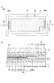
- FIG. 1 is a diagram illustrating the laminated glass according to the first embodiment, and FIG. 1A schematically shows a state in which the laminated glass is attached to the vehicle and visually recognized from the outside of the vehicle interior to the inside of the vehicle.
- FIG. 1B is a partially enlarged cross-sectional view taken along the line AA of FIG. 1A.
- the laminated glass 10 is a laminated glass for a vehicle having a glass plate 11, a glass plate 12, an interlayer film 13, a shielding layer 14, and a dimming element 15.
- the shielding layer 14 is provided as needed.
- the laminated glass 10 may have a curved shape in the longitudinal direction and the lateral direction.
- the laminated glass 10 may have a shape curved only in the longitudinal direction or a shape curved only in the lateral direction.
- the laminated glass 10 has a rectangular shape, but the planar shape of the laminated glass 10 is not limited to a rectangular shape, and may be any shape including a trapezoidal shape.
- the laminated glass 10 can be applied to, for example, roof glass, rear glass, rear side glass, rear quarter glass, roof glass, extra glass, etc. for vehicles.
- the extra glass is glass attached to the rear side of the vehicle in order to improve the rear visibility of the driver of the vehicle.
- the glass plate 11 is a glass plate inside the vehicle that becomes the inside of the vehicle when the laminated glass 10 is attached to the vehicle.
- the glass plate 12 is a vehicle outer glass plate that becomes the outer side of the vehicle when the laminated glass 10 is attached to the vehicle.
- the glass plates 11 and 12 may have a predetermined curvature.
- the glass plate 11 and the glass plate 12 are a pair of glass plates facing each other, and the interlayer film 13 and the dimming element 15 are located between the pair of glass plates.
- the glass plate 11 and the glass plate 12 are fixed with the interlayer film 13 and the light control element 15 sandwiched between them.
- the interlayer film 13 is a film that joins the glass plate 11 and the glass plate 12.
- the interlayer film 13 is located between, for example, the intermediate film 131 bonded to the glass plate 11, the intermediate film 132 bonded to the glass plate 12, and the intermediate film 131 and the intermediate film 132, and surrounds the outer periphery of the dimming element 15. It has a frame-shaped interlayer film 133.
- the interlayer film 13 may have an interlayer film 131 to be bonded to the glass plate 11 and an intermediate film 132 to be bonded to the glass plate 12, and may not have the interlayer film 133. Even if the interlayer film 133 is not provided, the outer periphery of the dimming element 15 is surrounded by the interlayer film 131 and / or 132 during crimping in the manufacturing process of the laminated glass 10.
- the interlayer film 13 When it is not necessary to distinguish between the interlayer films 131, 132, and 133, they are simply referred to as the interlayer film 13. Details of the glass plate 11, the glass plate 12, and the interlayer film 13 will be described later.
- the shielding layer 14 is an opaque layer, and can be provided in a strip shape along the peripheral edge of the laminated glass 10, for example.
- the shielding layer 14 is, for example, an opaque (eg, black) colored ceramic layer.
- the shielding layer 14 may be a colored interlayer film or a colored film having a light-shielding property, or a combination of the colored interlayer film and the colored ceramic layer.
- the colored film may be integrated with an infrared reflective film or the like.
- the presence of the opaque shielding layer 14 on the laminated glass 10 can suppress deterioration of the resin such as urethane that holds the peripheral edge of the laminated glass 10 on the vehicle body due to ultraviolet rays. Further, the electrodes electrically connected to the dimming element 15 and the electrode take-out wiring can be concealed so as to be difficult to see from the outside of the vehicle and / or the inside of the vehicle.
- the shielding layer 14 can be formed, for example, by applying a ceramic color paste containing a meltable glass frit containing a black pigment on a glass plate by screen printing or the like and firing it, but the shielding layer 14 is not limited thereto.
- the shielding layer 14 may be formed by, for example, applying an organic ink containing a black or dark pigment on a glass plate by screen printing or the like and drying it.
- the shielding layer 14 is provided on the peripheral edge of the inner surface of the glass plate 11.
- the shielding layer 14 may be provided on the peripheral edge of the vehicle inner surface of the glass plate 12, if necessary, the peripheral edge of the vehicle inner surface of the glass plate 11, and the vehicle inner surface of the glass plate 12. It may be provided on both edges of the glass.
- the dimming element 15 is an element capable of switching the light transmittance of the laminated glass 10.
- the dimming element 15 may be arranged on substantially the entire laminated glass 10 or only a part thereof, if necessary.
- the planar shape of the dimming element 15 is, for example, a rectangle smaller than the planar shape of the laminated glass 10. In the example of FIG. 1, the peripheral edge of the dimming element 15 is located at a position where it overlaps with the shielding layer 14 in a plan view.
- the light control element 15 includes a base material 151, a conductive film 152, a light control layer 153, a conductive film 154, a base material 155, and an electrode 156, and is enclosed in an interlayer film 13. That is, the dimming element 15 is covered with an interlayer film 13.
- the dimming element 15 is, for example, in the form of a film.
- the thickness of the dimming element 15 is, for example, 0.05 mm or more and 0.5 mm or less, preferably 0.1 mm or more and 0.4 mm or less.
- An electrode take-out wiring 16 for connecting the electrode 156 to an external circuit is connected to the electrode 156 of the dimming element 15.
- the base materials 151 and 155 are transparent resin layers.
- the thicknesses of the base materials 151 and 155 are, for example, 5 ⁇ m or more and 500 ⁇ m or less, preferably 10 ⁇ m or more and 200 ⁇ m or less, and more preferably 50 ⁇ m or more and 150 ⁇ m or less.
- the substrates 151 and 155 include, for example, polyethylene terephthalate, polyethylene naphthalate, polyamide, polyether, polysulphon, polyethersulphon, polycarbonate, polyarylate, polyetherimide, polyetheretherketone, polyimide, aramid, polybutylene terephthalate, and the like. It can be formed by any one selected from the group of triacetyl cellulose, polyurethane, and cycloolefin polymer.
- the conductive film 152 is formed on the surface of the base material 151 on the glass plate 12 side, and is in contact with the surface of the light control layer 153 on the glass plate 11 side.
- the conductive film 154 is formed on the surface of the base material 155 on the glass plate 11 side, and is in contact with the surface of the light control layer 153 on the glass plate 12 side. That is, the conductive films 152 and 154 are a pair of conductive films sandwiching the light control layer 153.
- TCO transparent conductive oxide
- ITO tin-added indium oxide
- AZO aluminum-added zinc oxide
- ITO tin-added indium oxide
- ITO tin-doped indium oxide
- AZO aluminum-added zinc oxide
- indium-added cadmium oxide examples include, but are not limited to, tin-added indium oxide (ITO: tin-doped indium oxide), aluminum-added zinc oxide (AZO: aluminum doped zinc oxide), and indium-added cadmium oxide.
- conductive films 152 and 154 transparent conductive polymers such as poly (3,4-ethylenedioxythiophene) (PEDOT) or poly (4,4-dioctylcyclopentadithiophene) can also be preferably used.
- transparent conductive polymers such as poly (3,4-ethylenedioxythiophene) (PEDOT) or poly (4,4-dioctylcyclopentadithiophene) can also be preferably used.
- PEDOT poly (3,4-ethylenedioxythiophene)
- poly (4,4-dioctylcyclopentadithiophene) poly(1,4-dioctylcyclopentadithiophene)
- a laminated film of a metal layer and a dielectric layer silver nanowires, a metal mesh of silver or copper and the like can also be preferably used.
- the conductive films 152 and 154 can be formed by using, for example, a physical vapor deposition method (PVD: Physical Vapor Deposition) such as a sputtering method, a vacuum vapor deposition method, or an ion plating method.
- PVD Physical vapor deposition
- the conductive films 152 and 154 may be formed by using a chemical vapor deposition (CVD) method or a wet coating method.
- the dimming layer 153 is sandwiched between the base material 151 on which the conductive film 152 is formed and the base material 155 on which the conductive film 154 is formed.
- the dimming layer 153 for example, any one or more selected from the group of suspended particle device (SPD: Suspended Particle Device), guest host liquid crystal, photochromic, electrochromic, and electrokinetic can be selected.
- SPD suspended particle device
- guest host liquid crystal for example, any one or more selected from the group of suspended particle device (SPD: Suspended Particle Device), guest host liquid crystal, photochromic, electrochromic, and electrokinetic can be selected.
- the dimming element 15 is arranged so as to face each other, the base material 151 on which the conductive film 152 is formed, the base material 155 on which the conductive film 154 is formed, and the conductive film 152 and the conductive film 154 facing each other. It has a dimming layer 153 composed of any one or more selected from the group of suspended particle device, guest host liquid crystal, photochromic, electrochromic, and electrokinetic arranged between and.
- the suspended particle device is a general SPD film configured by sandwiching a polymer layer containing suspended particles that can be oriented by applying a voltage between two substrates coated with a conductive film inside. Can be used.
- Such an SPD film has a high visible light transmittance and a high transparency by orienting the suspended particles in the polymer layer by turning on the power switch and applying a voltage between the transparent conductive films. Become. When the power switch is off, the suspended particles in the polymer layer are not oriented, the visible light transmittance is low, and the transparency is low.
- the SPD film for example, a commercially available product such as LCF-1103DHA (trade name, manufactured by Hitachi Kasei Co., Ltd.) can be used. Since such a commercially available product is supplied in a predetermined size, it is cut into a desired size before use.
- the thickness of the SPD film is not particularly limited, but is preferably 0.1 mm or more and 0.4 mm or less from the viewpoint of handleability and availability.
- the electrode 156 is arranged at a position overlapping the shielding layer 14 in a plan view, for example.
- the electrode 156 is inserted between the conductive film 152 and the conductive film 154.
- the first main surface and the second main surface of the electrode 156 are in contact with a film other than the interlayer film 13.
- the first main surface of the electrode 156 is a surface facing the glass plate 11 side.
- the second main surface of the electrode 156 is a surface opposite to the first main surface and faces the glass plate 12 side.
- the electrodes 156 are electrically separated vertically through an insulating layer (not shown), one of the upper and lower electrodes is electrically connected to the conductive film 152, and the other upper and lower electrodes are electrically connected to the conductive film 154. , The conductive films 152 and 154 are energized to drive the dimming layer 153. That is, the first main surface of the electrode 156 is in contact with the conductive film 152, and the second main surface of the electrode 156 is in contact with the conductive film 154.
- One pole of the electrode 156 is, for example, a positive electrode, and is connected to the positive side of a power source such as a battery mounted on a vehicle via an electrode take-out wiring 16 electrically connected to one pole of the electrode 156.
- the other pole of the electrode 156 is, for example, a negative electrode, and is connected to the negative side of a power source such as a battery mounted on a vehicle via an electrode take-out wiring 16 electrically connected to the other pole of the electrode 156.
- the transmittance of the dimming layer 153 is switched according to the voltage.
- the material of the electrode 156 is not particularly limited as long as it is a conductive material, and examples thereof include a metal material.
- metal materials include gold, silver, copper, aluminum, tungsten, platinum, palladium, nickel, cobalt, titanium, iridium, zinc, magnesium, tin and the like. Further, these metals may be plated or may be composed of a composite with an alloy or a resin.
- a copper ribbon, a flat braided copper wire, or an FPC Flexible Printed Circuit
- the copper ribbon or flat braided conductor may be plated with a metal other than copper.
- the electrode 156 can be bonded to the conductive films 152 and 154 by any of a conductive adhesive material (conductive adhesive layer), an anisotropic conductive film, and solder. Further, the electrode 156 may be brought into direct contact with the conductive films 152 and 154 without using a conductive adhesive material, an anisotropic conductive film, or solder. Alternatively, the electrode 156 may be formed by a printing method such as screen printing, inkjet printing, offset printing, flexographic printing, or gravure printing.
- the electrode 156 has a length and shape necessary and sufficient for energizing the dimming element 15.
- the shape of the electrode 156 is not particularly limited, but is generally substantially rectangular. Since the electrode 156 needs to be concealed by the shielding layer 14, for example, the glass plates 11 and 12 are placed on either end (the short side of either one) of the dimming element 15 in the longitudinal direction. It is arranged substantially parallel to the peripheral edge.
- the electrode 156 is preferably arranged 10 mm or more inward from the peripheral edges of the glass plates 11 and 12, and more preferably 15 mm or more inward. With such an arrangement, it is possible to reduce the possibility that moisture invades from the peripheral edges of the glass plates 11 and 12 and causes corrosion of the electrodes 156 and short circuits between different potentials.
- the length of the electrode 156 is not particularly limited, but is preferably 5 mm or more in consideration of ensuring a sufficient energizing function and improving workability. As will be described later, a plurality of electrodes 156 may exist, and they may be arranged on the same side or may be arranged so as to face the opposite sides.
- the handleability is improved, and the contact area with the conductive films 152 and 154 can be sufficiently secured, so that the function as an electrode is fully exhibited. It will be possible.
- the shielding layer 14 facilitates concealment and improves the design.
- the thickness of the electrode 156 is preferably 0.05 mm to 0.4 mm.
- the thickness of the electrode 156 is preferably 0.05 mm to 0.4 mm.
- the dimming element 15 has an electrode forming portion in which the electrode 156 is formed and an electrode non-forming portion in which the electrode 156 is not formed.
- the electrode forming portion is a portion that overlaps with the electrode 156 in a plan view, and does not include an inclined portion (a portion whose thickness decreases as the distance from the electrode 156 increases) around the electrode 156.
- all parts other than the electrode forming part are electrode non-forming parts.
- the dimming element 15 includes a first reference surface 158 and a second reference surface 159 that serve as a reference when defining the height of the electrode forming portion.
- the first reference surface 158 is a non-electrode forming portion and is a surface in contact with the interlayer film 131 on the glass plate 11 side in a portion where the thickness of the dimming element 15 is substantially constant.
- the height of the electrode forming portion when the first reference surface 158 is used as a reference is lower than the first reference surface 158 when the glass plate 11 side is in the positive direction with respect to the first reference surface 158.
- the problem is the magnitude of the absolute value of the height of the electrode forming portion. Therefore, hereinafter, the average value of the heights of the electrode forming portions with respect to the first reference plane 158 is the average of the absolute values of the heights of the electrode forming portions with respect to the first reference plane 158. Means a value.
- the height of the electrode forming portion when the second reference surface 159 is used as a reference is lower than the second reference surface 159 when the glass plate 12 side is in the positive direction with respect to the second reference surface 159.
- the problem is the magnitude of the absolute value of the height of the electrode forming portion. Therefore, hereinafter, the average value of the heights of the electrode forming portions with respect to the second reference plane 159 is the average of the absolute values of the heights of the electrode forming portions with respect to the second reference plane 159. Means a value.
- the portion where the thickness of the dimming element 15 is substantially constant is defined as an inclined portion around the electrode 156 in FIG. 1 (b) in the electrode non-forming portion and a side wall of the electrode 156 A 2 in FIG. 3 described later. This is a portion excluding the exposed recess 15x. Therefore, the inclined portion around the electrode 156 and the recess 15x described later are not included in the first reference surface 158.
- the second reference surface 159 is a non-electrode forming portion and is a surface in contact with the interlayer film 132 on the glass plate 12 side in a portion where the thickness of the dimming element 15 is substantially constant. Therefore, the inclined portion around the electrode 156 is not included in the second reference plane 159.
- t1 indicates an average value [mm] of the height (absolute value) of the electrode forming portion when the first reference surface 158 of the dimming element 15 is used as a reference.
- t2 indicates an average value [mm] of the height (absolute value) of the electrode forming portion when the second reference surface 159 of the dimming element 15 is used as a reference.
- w indicates the length [mm] of the electrode 156 in the lateral direction.
- t1, t2, and w are 0 ⁇ w ⁇ t1 ⁇ 0.7 and 0 ⁇ w ⁇ t2 ⁇ 0.7 (however, 3 ⁇ w ⁇ 20).
- -It is determined to satisfy the equation (1).
- T1 and w are determined so that the value [mm 2 ] multiplied by [mm] is 0 [mm 2 ] or more and 0.7 [mm 2] or less.
- t2 and w are determined so as to be 0 [mm 2 ] or more and 0.7 [mm 2] or less.
- t1 and t2 are determined so as to satisfy the equation (1) for the average value of w. To.
- a laminated body in which the glass plate 11, the interlayer film 131, the dimming element 15, the interlayer film 133, the intermediate film 132, and the glass plate 12 are sequentially laminated is prepared. Then, the prepared laminate is placed in, for example, a rubber bag, and the inside of the rubber bag is heated while being sucked under reduced pressure (deaeration treatment) and pre-crimped. If necessary, the pre-crimped laminate is placed in, for example, an autoclave. Heat and pressurize the bag to perform main bonding (main crimping).
- the degassing property deteriorates in the process of manufacturing the laminated glass 10, and appearance defects such as foaming and air residue occur.
- the thickness deviation around the electrode is reduced. Therefore, in the process of manufacturing the laminated glass 10, it is possible to suppress poor deaeration around the electrodes (improve the exhaustability of residual air), and it is possible to prevent the occurrence of appearance defects such as foaming and residual air.
- t1, t2, and w satisfy the formula (1), and t1 ⁇ 0.15 [mm] and t2 ⁇ 0.15 [mm]. By satisfying this requirement, in the step of manufacturing the laminated glass 10, it is possible to further suppress the degassing defect around the electrode.
- the glass plate 11, the glass plate 12, and the interlayer film 13 will be described in detail.
- the glass plates 11 and 12 may be inorganic glass or organic glass.
- the inorganic glass for example, soda lime glass, aluminosilicate glass, borosilicate glass, non-alkali glass, quartz glass and the like are used without particular limitation.
- the glass plate 12 located on the outside of the laminated glass 10 is preferably inorganic glass from the viewpoint of scratch resistance, and is preferably soda lime glass from the viewpoint of moldability.
- the glass plate 11 and the glass plate 12 are soda lime glass, clear glass, green glass containing an iron component in a predetermined amount or more, and UV-cut green glass can be preferably used.
- the inorganic glass may be either untempered glass or tempered glass.
- Untempered glass is made by molding molten glass into a plate shape and slowly cooling it. Tempered glass is formed by forming a compressive stress layer on the surface of untempered glass.
- the tempered glass may be either physically tempered glass such as wind-cooled tempered glass or chemically tempered glass.
- physically tempered glass for example, a glass plate uniformly heated in bending molding is rapidly cooled from a temperature near the softening point, or by an operation other than slow cooling, the temperature difference between the glass surface and the inside of the glass causes the glass surface to become.
- the glass surface can be strengthened.
- the glass surface can be strengthened by generating compressive stress on the glass surface by an ion exchange method or the like.
- a glass that absorbs ultraviolet rays or infrared rays may be used, and more preferably, a glass plate colored to such an extent that the transparency is not impaired may be used.
- examples of the material of organic glass include polycarbonate, for example, acrylic resin such as polymethylmethacrylate, and transparent resin such as polyvinyl chloride and polystyrene.
- the shapes of the glass plates 11 and 12 are not particularly limited to a rectangular shape, and may be a shape processed into various shapes and curvatures. Gravity molding, press molding, roller molding and the like are used for bending molding of the glass plates 11 and 12.
- the molding method of the glass plates 11 and 12 is not particularly limited, but for example, in the case of inorganic glass, a glass plate molded by a float method or the like is preferable.
- the thinnest portion of the glass plate 12 is preferably 1.1 mm or more and 3 mm or less.
- the strength such as stepping stone resistance is sufficient, and when it is 3 mm or less, the mass of the laminated glass 10 does not become too large, which is preferable in terms of fuel efficiency of the vehicle. ..
- the thinnest portion of the glass plate 12 is more preferably 1.8 mm or more and 2.8 mm or less, further preferably 1.8 mm or more and 2.6 mm or less, and further preferably 1.8 mm or more and 2.2 mm or less. More preferably, it is 8 mm or more and 2.0 mm or less.
- the thickness of the glass plate 11 is preferably 0.3 mm or more and 2.3 mm or less.
- the handleability is good, and when it is 2.3 mm or less, the mass does not become too large.
- the glass plates 11 and 12 may have a flat plate shape or a curved shape.
- the glass plates 11 and 12 have a curved shape and the thickness of the glass plates 11 is not appropriate, when two glass plates 11 and 12 having a particularly deep bend are formed, a mismatch occurs between the two shapes. , It greatly affects the glass quality such as residual stress after crimping.
- the plate thickness of the glass plate 11 is set to 0.3 mm or more and 2.3 mm or less.
- Setting the plate thickness of the glass plate 11 to 0.3 mm or more and 2.3 mm or less is particularly effective for maintaining the glass quality in deeply bent glass.
- the thickness of the glass plate 11 is more preferably 0.5 mm or more and 2.1 mm or less, and further preferably 0.7 mm or more and 1.9 mm or less. Within this range, the above effect becomes even more remarkable.
- a coating having a water-repellent, ultraviolet or infrared blocking function, or a coating having low reflection characteristics and low radiation characteristics may be provided on the outside of the glass plate 11 and / or 12. Further, a film having ultraviolet or infrared ray blocking, low radiation characteristics, visible light absorption, coloring or the like may be provided on the side of the glass plate 11 and / or 12 in contact with the interlayer film 13.
- the glass plates 11 and 12 are curved inorganic glass, the glass plates 11 and 12 are bent and molded after being molded by the float method and before being bonded by the interlayer film 13. Bending molding is performed by softening the glass by heating. The heating temperature of the glass during bending is approximately 550 ° C to 700 ° C.
- thermoplastic resin is often used as the interlayer film 13, and for example, a plasticized polyvinyl acetal resin, a plasticized polyvinyl chloride resin, a saturated polyester resin, a plasticized saturated polyester resin, a polyurethane resin, and a plasticized polyurethane resin are used.
- thermoplastic resins conventionally used for this type of application such as resins, ethylene-vinyl acetate copolymer resins, ethylene-ethyl acrylate copolymer resins, cycloolefin polymer resins, and ionomer resins.
- the resin composition containing the modified block copolymer hydride described in Japanese Patent No. 6065221 can also be preferably used.
- plasticized polyvinyl acetal-based resins have an excellent balance of various performances such as transparency, weather resistance, strength, adhesive strength, penetration resistance, impact energy absorption, moisture resistance, heat insulation, and sound insulation. Is preferably used. These thermoplastic resins may be used alone or in combination of two or more. "Plasticization" in the plasticized polyvinyl acetal-based resin means that it is plasticized by adding a plasticizer. The same applies to other plasticized resins.
- the dimming element 15 when the dimming element 15 is enclosed in the interlayer film 13, it may be deteriorated by a specific plasticizer depending on the type of the object to be enclosed.
- a resin that does not substantially contain the plasticizer Is preferably used. That is, it may be preferable that the interlayer film 13 does not contain a plasticizer.
- the resin containing no plasticizer include an ethylene-vinyl acetate copolymer resin.
- the polyvinyl acetal resin is a polyvinyl formal resin obtained by reacting polyvinyl alcohol (hereinafter, may also be referred to as “PVA” if necessary) with formaldehyde, and a narrow sense obtained by reacting PVA with acetaldehyde.
- Polyvinyl butyral resin obtained by reacting PVA with n-butylaldehyde hereinafter, may be referred to as "PVB” if necessary
- PVB is preferable because it has an excellent balance of various performances such as strength, adhesive strength, penetration resistance, impact energy absorption, moisture resistance, heat insulation, and sound insulation.
- These polyvinyl acetal-based resins may be used alone or in combination of two or more.
- the material forming the interlayer film 13 is not limited to the thermoplastic resin. Further, the interlayer film 13 may contain functional particles such as an infrared absorber, an ultraviolet absorber, and a luminescent agent. Further, the interlayer film 13 may have a colored portion called a shade band.
- the film thickness of the interlayer film 13 is preferably 0.5 mm or more at the thinnest part. When the film thickness of the thinnest portion of the interlayer film 13 is 0.5 mm or more, the impact resistance required for the laminated glass 10 is sufficient.
- the film thickness of the interlayer film 13 is preferably 3 mm or less at the thickest portion. When the maximum value of the film thickness of the interlayer film 13 is 3 mm or less, the mass of the laminated glass 10 does not become too large.
- the maximum value of the film thickness of the interlayer film 13 is more preferably 2.8 mm or less, and further preferably 2.6 mm or less.
- the interlayer film 13 may have four or more layers. For example, by forming an interlayer film from four or more layers and making the shear modulus of any layer excluding the layers on both sides smaller than the shear modulus of the layers on both sides by adjusting a plasticizer or the like, the laminated glass 10 is formed. Sound insulation can be improved. In this case, the shear modulus of the layers on both sides may be the same or different.
- the interlayer films 131, 132, and 133 contained in the interlayer film 13 are all formed of the same material, but a part or all of the interlayer films 131, 132, and 133 are formed of different materials. May be good.
- the material may have a shear modulus smaller than that of the interlayer films 131 and 132.
- the shear modulus of the interlayer film 133 is smaller than the shear modulus of the interlayer films 131 and 132, the sound insulation of the laminated glass 10 can be improved.
- the shear modulus of the interlayer film 132 is smaller than the shear modulus of the interlayer film 131 and 133, the sound insulation of the laminated glass 10 can be improved.
- the above resin material to be an interlayer film is appropriately selected and extruded in a heat-melted state using an extruder.
- the extrusion conditions such as the extrusion speed of the extruder are set to be uniform.
- the interlayer film 13 is completed by stretching the extruded resin film, for example, as necessary, in order to give curvature to the upper side and the lower side according to the design of the laminated glass 10.
- the total thickness of the laminated glass 10 is preferably 2.8 mm or more and 10 mm or less. When the total thickness of the laminated glass 10 is 2.8 mm or more, sufficient rigidity can be secured. Further, when the total thickness of the laminated glass 10 is 10 mm or less, sufficient transmittance can be obtained and haze can be reduced.
- the plate deviation between the glass plate 11 and the glass plate 12 is preferably 1.5 mm or less, and more preferably 1 mm or less.
- the plate deviation between the glass plate 11 and the glass plate 12 is, that is, the amount of deviation between the end portion of the glass plate 11 and the end portion of the glass plate 12 in a plan view.
- the plate deviation between the glass plate 11 and the glass plate 12 is 1.5 mm or less on at least one side of the laminated glass 10, it is preferable in that the appearance is not impaired. It is more preferable that the plate deviation between the glass plate 11 and the glass plate 12 is 1.0 mm or less on at least one side of the laminated glass 10 in that the appearance is not impaired.
- an interlayer film 13 and a dimming element 15 are sandwiched between the glass plate 11 and the glass plate 12 to form a laminated body. Then, for example, this laminate is placed in a rubber bag and bonded at a temperature of about 70 ° C. to 110 ° C. in a vacuum having a gauge pressure of ⁇ 65 kPa to ⁇ 100 kPa.
- the heating conditions, temperature conditions, and laminating method are appropriately selected in consideration of the properties of the dimming element 15, for example, so as not to deteriorate during laminating.
- a laminated glass 10 having more excellent durability can be obtained.
- this heating and pressurizing step may not be used in consideration of the simplification of the step and the characteristics of the material to be sealed in the laminated glass 10.
- the glass plate 11 and the glass plate 12 in addition to the interlayer film 13 and the dimming element 15, heating wire, infrared reflection, light emission, power generation, dimming, touch panel, visible light, as long as the effect of the present application is not impaired.
- It may have a film or device having functions such as reflection, scattering, decoration, and absorption.
- the surface of the laminated glass 10 may have a film having functions such as anti-fog, water-repellent, heat-shielding, and low reflection.
- a film having functions such as heat shielding and heat generation may be provided on the outer surface of the glass plate 11 and the inner surface of the glass plate 12.
- the thickness deviation around the electrode is reduced. Therefore, in the process of manufacturing the laminated glass 10, it is possible to suppress poor deaeration around the electrodes (improve the exhaustability of residual air), and it is possible to prevent the occurrence of appearance defects such as foaming and residual air.
- Modification 1 of the first embodiment shows an example of a laminated glass provided with a dimming element having an electrode structure different from that of the first embodiment.
- the description of the same components as those of the above-described embodiment may be omitted.
- FIG. 2 is a diagram illustrating the laminated glass according to the first modification of the first embodiment, and FIG. 2A schematically shows a state in which the laminated glass is attached to the vehicle and visually recognized from the outside of the vehicle interior to the inside of the vehicle. ing.
- FIG. 2B is a partially enlarged cross-sectional view taken along the line BB of FIG. 2A.
- the laminated glass 10A is different from the laminated glass 10 (see FIG. 1) in that the dimming element 15 is replaced with the dimming element 15A.
- the dimming element 15A differs from the dimming element 15 having one electrode 156 (see FIG. 1) in that it has a pair of electrodes 156A 1 and 156A 2.
- the configuration of the dimming element 15A other than the electrodes 156A 1 and 156A 2 is the same as that of the dimming element 15.
- the electrodes 156A 1, electrode lead-out wiring 16 1 for connecting the electrodes 156A 1 and the external circuit is connected. Further, the electrodes 156A 2, electrode lead wires 16 2 for connecting the electrode 156A 2 and the external circuit are connected.
- the electrodes 156A 1 and 156A 2 are arranged, for example, at positions overlapping the shielding layer 14 in a plan view.
- the 156A 1 and 156A 2 are arranged in the portion where the dimming element 15A is half-cut.
- the electrode 156A 1 is arranged so that the first main surface is in contact with the surface of the conductive film 152 exposed by partially removing the base material 155, the conductive film 154, and the dimming layer 153. ..
- the second main surface of the electrode 156A 1 is in contact with the interlayer film 132.
- the electrodes 156A 2 are arranged so that the second main surface is in contact with the surface of the conductive film 154 exposed by partially removing the base material 151, the conductive film 152, and the light control layer 153.
- the first main surface of the electrode 156A 2 is in contact with the interlayer film 131.
- the first main surface of the electrodes 156A 1 and 156A 2 is a surface facing the glass plate 11 side.
- the second main surface of the electrodes 156A 1 and 156A 2 is a surface opposite to the first main surface and faces the glass plate 12 side.
- Electrodes 156A 1 is, for example, a positive electrode, via the electrode lead wires 16 1, is connected to the positive side of the power supply such as a battery mounted on the vehicle.
- the electrode 156A 2 is a negative electrode for example, via the electrode lead wire 16 2 is connected to the negative side of the power supply such as a battery mounted on the vehicle.
- the transmittance of the dimming layer 153 is switched according to the voltage.
- the materials of the electrodes 156A 1 and 156A 2 , the bonding method with the conductive film, the length, the width, and the thickness are the same as those exemplified for the electrode 156 in the first embodiment.
- the peripheral portions of the glass plates 11 and 12 are formed on both ends (both short sides) of the dimming element 15A in the longitudinal direction. Arranged substantially parallel to (edge).
- the electrodes 156A 1 and 156A 2 are preferably arranged 10 mm or more inward from the peripheral edges of the glass plates 11 and 12, and more preferably 15 mm or more inward. With such an arrangement, it is possible to reduce the possibility that moisture invades from the peripheral edges of the glass plates 11 and 12 and causes corrosion of the electrodes 156A 1 and 156A 2 and a short circuit between different potentials.
- t1, t2, and w are determined to satisfy the formula (1).
- t2 0 because there is no step on the second reference surface 159 side.
- the length of the electrode 156A 1 in the lateral direction is w1
- the length of the electrode 156A 2 in the lateral direction is w2
- w1 ⁇ w2 each of w1 and w2 satisfies the equation (1).
- connection between the electrode and the conductive film is not particularly limited, and may be an insertion type electrode as shown in FIG. 1 or a half-cut type electrode as shown in FIG.
- the thickness deviation around the electrode is reduced by satisfying the equation (1) with t1, t2, and w of the laminated glass. Therefore, in the process of manufacturing the laminated glass, it is possible to suppress poor deaeration around the electrodes (improve the exhaust property of residual air), and it is possible to prevent the occurrence of appearance defects such as foaming and residual air.
- t1, t2, and w satisfy the formula (1) and t1 ⁇ 0.15 [mm]. By satisfying this requirement, it is possible to further suppress poor degassing around the electrodes in the step of manufacturing the laminated glass 10A.
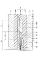
- FIG. 3 is a diagram illustrating a recess formed in the electrode non-forming portion.
- E 1 shows an electrode forming portion
- E 2 shows an electrode non-forming portion.
- the electrode forming portion E of the electrode non-forming portion E 2 is formed in a vertical cross section along a direction parallel to the lateral direction of the electrode 156A 2 .
- the end of the 1 side, the recess 15x for exposing the sidewalls of the electrode 156A 2 are formed (the same applies to the end portion of the electrode 156A 1 side).
- Recess 15x is recessed from the first reference surface 158 side of the non-electrode portion E 2 to the conductive film 154 side, bottom is formed by the conductive film 154.
- the height t3 of the first side wall of the recess 15x which is the side wall of the electrode 156A 2 , and the electrode non-forming portion E 2 side facing the first side wall.
- the distance wx between the first side wall and the second side wall is short in terms of improving degassing property.
- the distance wx between the first side wall and the second side wall is 5 mm or less, the effect on degassing is small, and when the distance wx is 3 mm or less, the effect on degassing is even smaller. If it is 2 mm or less, it is preferable because it has less influence on degassing.
- the height t3 of the first side wall of the recess 15x which is the side wall of the electrode 156A 2 , and the electrode non-forming portion E 2 side facing the first side wall.
- the height t4 of the second side wall of the above is larger than 0.15 mm.
- the distance wx between the first side wall and the second side wall is short in terms of improving degassing property.
- the distance wx between the first side wall and the second side wall is 5 mm or less, the effect on degassing is small, and when the distance wx is 3 mm or less, the effect on degassing is even smaller. If it is 2 mm or less, it is preferable because it has less influence on degassing.
- the second modification of the first embodiment shows an example of a laminated glass provided with a dimming element having an electrode arrangement different from that of the first modification of the first embodiment.
- the description of the same component as that of the above-described embodiment may be omitted.
- FIG. 4 is a plan view illustrating the laminated glass according to the second modification of the first embodiment, and schematically shows a state in which the laminated glass is attached to the vehicle and visually recognized from the outside of the vehicle interior to the inside of the vehicle interior.
- the laminated glass 10B is different from the laminated glass 10A (see FIG. 2) in that the dimming element 15A is replaced with the dimming element 15B.
- the dimming element 15B differs from the dimming element 15A (see FIG. 2) having a pair of electrodes 156A 1 and 156A 2 in that it has a pair of electrodes 156B 1 and 156B 2.
- the configuration of the dimming element 15B other than the electrodes 156B 1 and 156B 2 is the same as that of the dimming element 15A.
- the electrode 156B 1, the electrode take-out wiring 16 1 for connecting the electrode 156B 1 and the external circuit is connected. Further, the electrode 156B 2, electrode lead wires 16 2 for connecting the electrode 156B 2 and the external circuit is connected.
- the materials of the electrodes 156B 1 and 156B 2 , the bonding method with the conductive film, the length, the width, and the thickness are the same as those exemplified for the electrode 156 in the first embodiment.
- a glass plate is attached to either end (the short side of either one) of the dimming element 15B in the longitudinal direction. It is arranged substantially parallel to the peripheral edges (edges) of 11 and 12.
- the electrodes 156B 1 and 156B 2 are preferably arranged 10 mm or more inward from the peripheral edges of the glass plates 11 and 12, and more preferably 15 mm or more inward. With such an arrangement, it is possible to reduce the possibility that moisture invades from the peripheral edges of the glass plates 11 and 12 and causes corrosion of the electrodes 156B 1 and 156B 2 and a short circuit between different potentials.
- t1, t2, and w are determined to satisfy the formula (1).
- t2 0 because there is no step on the second reference surface 159 side.
- the length of the electrode 156B 1 in the lateral direction is w1
- the length of the electrode 156B 2 in the lateral direction is w2
- w1 ⁇ w2 each of w1 and w2 satisfies the equation (1).
- t1, t2, and w satisfy the formula (1) and t1 ⁇ 0.15 [mm]. By satisfying this requirement, it is possible to further suppress poor degassing around the electrodes in the step of manufacturing the laminated glass 10B.
- the laminated glass 10B has electrodes 156B 1 and B 2 at the end of the non-electrode formed portion on the electrode forming portion side in a vertical cross section along a direction parallel to the lateral direction of the electrode. A recess is formed that exposes the side wall.
- the distance between the first side wall and the second side wall is 5 mm or less. If it is, it is preferable in that the influence on degassing is small, if it is 3 mm or less, it is preferable in that the influence on degassing is further small, and if it is 2 mm or less, it is preferable in that the influence on degassing is further small.
- both the height of the first side wall and the height of the second side wall of the recess are larger than 0.15 mm, if the distance between the first side wall and the second side wall is 5 mm or less, the effect on degassing is affected. It is preferable in that it is small, and it is preferable that it is 3 mm or less because it has a smaller effect on degassing, and it is preferable that it is 2 mm or less because it has a smaller effect on degassing.
- the pair of electrodes may be arranged so as to face each other on the peripheral edges of the glass plates 11 and 12, or are arranged in a row on the same side of the peripheral edges of the glass plates 11 and 12 at predetermined intervals. May be done.
- the thickness deviation around the electrode is reduced by satisfying the equation (1) with t1, t2, and w of the laminated glass. Therefore, in the process of manufacturing the laminated glass, it is possible to suppress poor deaeration around the electrodes (improve the exhaust property of residual air), and it is possible to prevent the occurrence of appearance defects such as foaming and residual air.
- Modification 3 of the first embodiment shows another example of laminated glass provided with a dimming element having an electrode arrangement different from that of modification 1 of the first embodiment.
- the description of the same component as that of the above-described embodiment may be omitted.
- FIG. 5 is a plan view illustrating the laminated glass according to the modified example 3 of the first embodiment, and schematically shows a state in which the laminated glass is attached to the vehicle and visually recognized from the outside of the vehicle interior to the inside of the vehicle interior.
- the laminated glass 10C is different from the laminated glass 10A (see FIG. 2) in that the dimming element 15A is replaced with the dimming element 15C.
- Light control device 15C is that it has a pair of electrodes 156C 1 and 156C 2 are, different from the light control element 15A having a pair of electrodes 156A 1 and 156A 2 (see FIG. 2).
- the configuration of the dimming element 15C other than the electrodes 156C 1 and 156C 2 is the same as that of the dimming element 15A.
- the electrode 156C 1, electrode lead-out wiring 16 1 for connecting the electrode 156C 1 and an external circuit is connected. Further, the electrode 156C 2, electrode lead wires 16 2 for connecting the electrode 156C 2 and the external circuit is connected.
- the materials of the electrodes 156C 1 and 156C 2 , the bonding method with the conductive film, the length, the width, and the thickness are the same as those exemplified for the electrode 156 in the first embodiment.
- the electrodes 156C 1 and 156C 2 need to be concealed by the shielding layer 14, for example, glass is attached to either end (the long side of either one) of the dimming element 15C in the lateral direction. It is arranged substantially parallel to the peripheral edges (edges) of the plates 11 and 12.
- the electrodes 156C 1 and 156C 2 are preferably arranged 10 mm or more inward from the peripheral edges of the glass plates 11 and 12, and more preferably 15 mm or more inward. With such an arrangement, it is possible to reduce the possibility that moisture invades from the peripheral edges of the glass plates 11 and 12 and causes corrosion of the electrodes 156C 1 and 156C 2 and a short circuit between different potentials.
- t1, t2, and w are determined to satisfy the formula (1).
- t2 0 because there is no step on the second reference surface 159 side.
- the length of the electrode 156C 1 in the lateral direction is w1
- the length of the electrode 156C 2 in the lateral direction is w2
- w1 ⁇ w2 each of w1 and w2 satisfies the equation (1).
- t1, t2, and w satisfy the formula (1) and t1 ⁇ 0.15 [mm]. By satisfying this requirement, it is possible to further suppress poor degassing around the electrodes in the step of manufacturing the laminated glass 10C.
- the laminated glass 10C has electrodes 156C 1 and C 2 at the end of the non-electrode forming portion on the electrode forming portion side in a vertical cross section along a direction parallel to the lateral direction of the electrode. A recess is formed that exposes the side wall.
- the distance between the first side wall and the second side wall is 5 mm or less. If it is, it is preferable in that the influence on degassing is small, if it is 3 mm or less, it is preferable in that the influence on degassing is further small, and if it is 2 mm or less, it is preferable in that the influence on degassing is further small.
- both the height of the first side wall and the height of the second side wall of the recess are larger than 0.15 mm, if the distance between the first side wall and the second side wall is 5 mm or less, the effect on degassing is affected. It is preferable in that it is small, and it is preferable that it is 3 mm or less because it has a smaller effect on degassing, and it is preferable that it is 2 mm or less because it has a smaller effect on degassing.
- the pair of electrodes may be arranged so as to face each other at both ends in the longitudinal direction of the dimming element, or may be spaced apart from each other at either end in the longitudinal direction of the dimming element. They may be arranged in a row. Further, the dimming elements may be arranged in a row at a predetermined interval at any one end in the lateral direction.
- the thickness deviation around the electrode is reduced by satisfying the equation (1) with t1, t2, and w of the laminated glass. Therefore, in the process of manufacturing the laminated glass, it is possible to suppress poor deaeration around the electrodes (improve the exhaust property of residual air), and it is possible to prevent the occurrence of appearance defects such as foaming and residual air.
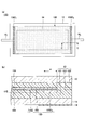
- FIG. 6 is a diagram illustrating the laminated glass according to the modified example 4 of the first embodiment, and FIG. 6A schematically shows a state in which the laminated glass is attached to the vehicle and visually recognized from the outside of the vehicle interior to the inside of the vehicle. ing.
- FIG. 6B is a partially enlarged cross-sectional view taken along the line CC of FIG. 6A.
- the laminated glass 10D differs from the laminated glass 10A (see FIG. 2) in that the dimming element 15A is replaced with the electric heating element 15D.
- the electric heating element 15D is an element capable of heating the laminated glass 10D. If necessary, the electric heating element 15D may be arranged on substantially the entire laminated glass 10D, or may be arranged only on a part of the laminated glass 10D.
- the planar shape of the electric heating element 15D is, for example, a rectangle.
- the outer edge portion of the electric heating element 15D is located, for example, at a position where it overlaps with the shielding layer 14 in a plan view.
- the electric heating element 15D is in the form of a film including a base material 155, a heat generating portion 154D, and electrodes 156D 1 and D 2, and is enclosed in an interlayer film 13. That is, the electric heating element 15D is surrounded by the interlayer film 13.
- the heat generating portion 154D can be formed from a conductive film such as gold, silver, copper, tin-doped indium oxide or the like.
- the heat generating portion 154D can be formed by using, for example, a physical vapor deposition method (PVD: Physical Vapor Deposition) such as a sputtering method, a vacuum vapor deposition method, or an ion plating method.
- PVD Physical Vapor Deposition
- the heat generating portion 154D may be formed by using a chemical vapor deposition method (CVD) or a wet coating method.
- a heating wire or a mesh-like metal may be used as the heat generating portion 154D.
- the material of the heating wire or the mesh-like metal is not particularly limited as long as it is a conductive material, and for example, at least one metal selected from the group consisting of gold, silver, copper, aluminum, nickel, and tungsten. Examples include alloys containing two or more metals selected from the group.
- the electrode 156D 1, electrode lead-out wiring 16 1 for connecting the electrode 156D 1 and the external circuit is connected. Further, the electrode 156D 2, electrode lead wires 16 2 for connecting the electrode 156D 2 to an external circuit are connected.
- the first main surfaces of the electrodes 156 D 1 and D 2 are in contact with the interlayer film 131.
- the second main surface of the electrodes 156D 1 and 156D 2 is in contact with the surface of the heat generating portion 154D.
- the first main surface of the electrodes 156D 1 and 156D 2 is a surface facing the glass plate 11 side.
- the second main surface of the electrodes 156D 1 and 156D 2 is a surface opposite to the first main surface and faces the glass plate 12 side.
- Electrode 156D 1 is, for example, a positive electrode, via the electrode lead wires 16 1, is connected to the positive side of the power supply such as a battery mounted on the vehicle. Further, the electrode 156D 2 is a negative electrode for example, via the electrode lead wire 16 2 is connected to the negative side of the power supply such as a battery mounted on the vehicle.
- the heat generating unit 154D When a voltage is supplied from a power source such as a battery to the heat generating unit 154D via the electrodes 156D 1 and 156D 2 , the amount of heat generated by the heat generating unit 154D is changed according to the voltage.
- the heat generating portion 154D When the heat generating portion 154D generates heat, the effect of eliminating the freezing of the moisture adhering to the laminated glass 10D (melting ice) and clearing the fogging (anti-fog) can be obtained.
- the materials of the electrodes 156D 1 and 156D 2 , the bonding method with the conductive film, the length, the width, and the thickness are the same as those exemplified for the electrode 156 in the first embodiment.
- the electrodes 156D 1 and 156D 2 need to be concealed by the shielding layer 14, for example, the peripheral portions of the glass plates 11 and 12 (on both short side sides) of the electric heating element 15D in the longitudinal direction (the peripheral portions of the glass plates 11 and 12). It is arranged approximately parallel to the edge).
- thermoelectric element 15D requires a uniform current distribution, it is preferable that the electrodes 156D 1 and 156D 2 are arranged over the entire side of the thermoelectric element 15D, as shown in FIG. 5A.
- the electrodes 156D 1 and 156D 2 are arranged over the entire side of the thermoelectric element 15D, as shown in FIG. 5A.
- a functional element such as the dimming element 15 that exerts its function by applying a voltage
- it may be arranged only on a part of the side as shown in FIG. 2A or the like.
- the electrodes 156D 1 and 156D 2 are preferably arranged 10 mm or more inward from the peripheral edges of the glass plates 11 and 12, and more preferably 15 mm or more inward. With such an arrangement, it is possible to reduce the possibility that moisture invades from the peripheral edges of the glass plates 11 and 12 and causes corrosion of the electrodes 156D 1 and 156D 2 and a short circuit between different potentials.
- t1, t2, and w are determined to satisfy the formula (1).
- t2 0 because there is no step on the second reference surface 159 side.
- the length of the electrode 156D 1 in the lateral direction is w1
- the length of the electrode 156D 2 in the lateral direction is w2
- w1 ⁇ w2 each of w1 and w2 satisfies the equation (1).
- t1, t2, and w satisfy the formula (1) and t1 ⁇ 0.15 [mm]. By satisfying this requirement, it is possible to further suppress poor degassing around the electrodes in the step of manufacturing the laminated glass 10D.
- the functional element sealed in the interlayer film is not limited to the dimming element, and may be, for example, an electric heating element. Even when the electric heating element is enclosed in the interlayer film of the laminated glass, the thickness deviation around the electrode is reduced by satisfying the equation (1) with t1, t2, and w of the laminated glass. Therefore, in the process of manufacturing the laminated glass, it is possible to suppress poor deaeration around the electrodes (improve the exhaust property of residual air), and it is possible to prevent the occurrence of appearance defects such as foaming and residual air.
- organic EL Organic Electro-Luminescence
- organic EL Organic Electro-Luminescence
- LED Light Emitting Diode
- liquid crystal display element In addition to dimming elements and electric heating elements, organic EL (Organic Electro-Luminescence) manufactured on a base material or bonded or bonded to a base material as a functional element that can be sealed in an interlayer film of laminated glass.
- organic EL Organic Electro-Luminescence
- examples thereof include inorganic EL (Inorganic Electro-Luminescence), LED (Light Emitting Diode), liquid crystal display element, and solar cell.
- the thickness deviation around the electrodes is reduced by satisfying the equation (1) with t1, t2, and w of the laminated glass. Therefore, in the process of manufacturing the laminated glass, it is possible to suppress poor deaeration around the electrodes (improve the exhaust property of residual air), and it is possible to prevent the occurrence of appearance defects such as foaming and residual air.
- the laminated glass 10D shown in FIG. 6 may be deformed like the laminated glass 10E shown in FIG. 7, the laminated glass 10F shown in FIG. 8, and the laminated glass 10G shown in FIG.
- the electric heating element 15E has electrodes 156D 3 that are stepped from the inside to the outside of the electric heating element 15E.
- the electric heating element 15F has an electrode 156D 4 that is inclined in a wedge shape from the inside to the outside of the electric heating element 15F.
- the base material 155G of the electric heating element 15G also functions as an interlayer film, and the second reference surface 159 side of the base material 155G is directly adhered to the glass plate 12.
- the first reference surface 158 side of the base material 155G is adhered to the glass plate 11 via the interlayer film 13.
- the material exemplified as the material of the interlayer film such as PVB can be used as the material of the base material 155G.
- Example 1 Examples and comparative examples will be described below, but the present invention is not limited to these examples. Of these, Examples 1, 3, 5, 7, 9, 11 and 12 are examples, and Examples 2, 4, 6, 8, 10 and 13 are comparative examples.
- Example 1 A glass plate (inside the car glass plate) that becomes the inner plate and a glass plate (outside the car glass plate) that becomes the outer plate when made into laminated glass were prepared (commonly known as VFL manufactured by AGC Inc.).
- the dimensions of the car inner glass plate and the car outer glass plate were 300 mm in length ⁇ 300 mm in width ⁇ 2 mm in thickness.
- two interlayer films (PVB manufactured by Solusia Japan, thickness 0.38 mm) were prepared. Then, one interlayer film, a PET film resembling a functional element, and the other interlayer film were sandwiched between the car inner glass plate and the car outer glass plate in this order to prepare a laminate. The position of the PET film as a functional element was adjusted so that the distance from the end of the glass plate to the end of the PET film was 40 mm.
- the laminate was placed in a rubber bag and bonded at a temperature of about 70 ° C. to 110 ° C. in a vacuum with a gauge pressure of -65 kPa to -100 kPa.
- the laminated glass for evaluation was prepared by heating and pressurizing under the conditions of a temperature of 100 ° C. to 150 ° C. and an absolute pressure of 0.6 MPa to 1.3 MPa. Two types of laminated glass for evaluation, in which the length of the PET film used as an electrode was 100 mm and 50 mm, were produced.
- Example 2 to 10 The size of each part of the PET film resembling an electrode was adjusted so that t1, t2, and w were the values shown in the columns of Examples 2 to 10 in FIG. 10, in the same manner as in Example 1.
- Laminated glass for evaluation was prepared.
- Example 11 to 13 An SPD film (manufactured by Hitachi Kasei Co., Ltd.) having a dimming layer thickness of 90 ⁇ m was used as a functional element, and a copper tape having a thickness of 70 ⁇ m was used as an electrode.
- the SPD film was half-cut to expose the transparent conductive film on one side, and a copper tape was attached thereto.
- the gap between the copper tape and the SPD film was prepared in two types of 3 mm (Example 11) and 5 mm (Examples 12 and 13). Further, the heights of the electrodes were made in two ways, 70 ⁇ m (Examples 11 and 12) and 210 ⁇ m (Example 13).
- a bake test 120 ° C., 2 hours was carried out on the laminated glass for evaluation, and after the bake test, the presence or absence of foaming of the interlayer film and air residue was visually confirmed.
- foaming or air residue was confirmed on the interlayer film, it was evaluated as x (failed), and when neither foaming or air residue was confirmed on the interlayer film, it was evaluated as ⁇ (passed).
- the evaluation results are shown in FIG. 10 together with the values of t1, t2, and w of the PET film as if it were an electrode. Further, it is shown in FIG. 11 together with the values of t1, t2, t3, t4, w, and wx of the copper tape actually used as the electrode. Since the evaluation results were exactly the same when the length of the PET film as an electrode was 100 mm and 50 mm, the length of the PET film as an electrode is not described in FIG. Since the evaluation results were exactly the same when the length of the copper tape used as the electrode was 100 mm and 50 mm, the length of the copper tape used as the electrode is not described in FIG.
Landscapes
- Chemical & Material Sciences (AREA)
- Crystallography & Structural Chemistry (AREA)
- Engineering & Computer Science (AREA)
- Mechanical Engineering (AREA)
- Joining Of Glass To Other Materials (AREA)
Abstract
本合わせガラスは、一対のガラス板と、前記一対のガラス板の間に位置する中間膜と、前記一対のガラス板の間に位置し、前記中間膜に接する機能素子と、を有し、前記機能素子は、導電膜と、前記導電膜と電気的に接続された電極と、をそれぞれ1つ以上有し、前記機能素子は、前記電極が形成されている電極形成部と、前記電極が形成されていない電極非形成部と、を有し、前記電極非形成部の前記一対のガラス板の一方側で前記中間膜と接する第1基準面と、前記一対のガラス板の他方側で前記中間膜と接する第2基準面と、を備え、前記第1基準面を基準としたときの前記電極形成部の高さの平均値をt1[mm]、前記第2基準面を基準としたときの前記電極形成部の高さの平均値をt2[mm]、前記電極の短手方向の長さをw[mm]としたときに、0≦w×t1≦0.7、かつ、0≦w×t2≦0.7(但し、3≦w≦20とする)を満たし、前記機能素子は、調光素子又は電熱素子であり、前記調光素子は、互いに対向して配置された、導電膜が形成された基材と、対向する前記基材の間に配置された、懸濁粒子デバイス、ゲストホスト液晶、フォトクロミック、エレクトロクロミック、エレクトロキネティックの群から選択される何れか一つ以上からなる調光層と、を有する。
Description
本発明は、合わせガラスに関する。
自動車や鉄道の窓ガラスで、通電可能な機能素子を中間膜に封入した合わせガラスが知られている。機能素子は、例えば、調光素子や電熱素子である。これらの機能素子には、機能層に通電するための電極が形成され、電極は機能層と共に合わせガラスに封入されることが一般的である。
しかし、電極を合わせガラスに封入すると、電極が形成されていない部分の機能素子の厚さと、電極が形成されている部分の機能素子の厚さに偏差が生じる。この偏差によって、合わせガラス作製時の脱気性が悪化し、空気残りや、中間膜の発泡という外観上の不具合が生じる場合があった。
そこで、脱気性の悪化の対策として、例えば、電極の厚みを厚くすることで、電極取出し配線における応力集中を緩和することが検討されている(例えば、特許文献1参照)。又、中間膜の構成を工夫することで厚さの偏差を調整することが検討されている(例えば、特許文献2参照)。
しかしながら、従来の対策方法では、電極周辺での脱気性の改善効果が不十分であった。
本発明は、上記の点に鑑みてなされたものであり、中間膜に機能素子を封入した合わせガラスにおいて、電極周辺での脱気性を向上することを目的とする。
本合わせガラスは、一対のガラス板と、前記一対のガラス板の間に位置する中間膜と、前記一対のガラス板の間に位置し、前記中間膜に接する機能素子と、を有し、前記機能素子は、導電膜と、前記導電膜と電気的に接続された電極と、をそれぞれ1つ以上有し、前記機能素子は、前記電極が形成されている電極形成部と、前記電極が形成されていない電極非形成部と、を有し、前記電極非形成部の前記一対のガラス板の一方側で前記中間膜と接する第1基準面と、前記一対のガラス板の他方側で前記中間膜と接する第2基準面と、を備え、前記第1基準面を基準としたときの前記電極形成部の高さの平均値をt1[mm]、前記第2基準面を基準としたときの前記電極形成部の高さの平均値をt2[mm]、前記電極の短手方向の長さをw[mm]としたときに、0≦w×t1≦0.7、かつ、0≦w×t2≦0.7(但し、3≦w≦20とする)を満たし、前記機能素子は、調光素子又は電熱素子であり、前記調光素子は、互いに対向して配置された、導電膜が形成された基材と、対向する前記基材の間に配置された、懸濁粒子デバイス、ゲストホスト液晶、フォトクロミック、エレクトロクロミック、エレクトロキネティックの群から選択される何れか一つ以上からなる調光層と、を有する。
開示の一実施態様によれば、中間膜に機能素子を封入した合わせガラスにおいて、電極周辺での脱気性を向上できる。
以下、図面を参照して発明を実施するための形態について説明する。各図面において、同一構成部分には同一符号を付し、重複した説明を省略する場合がある。又、各図面において、本発明の内容を理解しやすいように、大きさや形状を一部誇張している場合がある。
なお、車両とは、代表的には自動車であるが、電車、船舶、航空機等を含む、ガラスを有する移動体を指すものとする。
又、平面視とは合わせガラスの所定領域を合わせガラスの車内側の面の法線方向から視ることを指し、平面形状とは合わせガラスの所定領域を合わせガラスの車内側の面の法線方向から視た形状を指すものとする。
〈第1実施形態〉
図1は、第1実施形態に係る合わせガラスを例示する図であり、図1(a)は合わせガラスを車両に取り付けて車室外から車室内に視認した様子を模式的に示している。図1(b)は、図1(a)のA-A線に沿う部分拡大断面図である。
図1は、第1実施形態に係る合わせガラスを例示する図であり、図1(a)は合わせガラスを車両に取り付けて車室外から車室内に視認した様子を模式的に示している。図1(b)は、図1(a)のA-A線に沿う部分拡大断面図である。
図1を参照すると、合わせガラス10は、ガラス板11と、ガラス板12と、中間膜13と、遮蔽層14と、調光素子15とを有する車両用の合わせガラスである。但し、遮蔽層14は、必要に応じて設けられる。
なお、図1では、合わせガラス10を平板形状に示しているが、合わせガラス10は長手方向及び短手方向に湾曲した形状であってもよい。或いは、合わせガラス10は、長手方向のみに湾曲した形状や、短手方向のみに湾曲した形状であってもよい。
又、図1では、合わせガラス10を矩形状としているが、合わせガラス10の平面形状は矩形状には限定されず、台形状等を含む任意の形状として構わない。
合わせガラス10は、例えば、車両用のルーフガラス、リアガラス、リアサイドガラス、リアクォーターガラス、ルーフガラス、エクストラガラス等に適用できる。なお、エクストラガラスとは、車両の運転者の後方視認性を向上させるために、車両のリア側に取り付けられるガラスである。
ガラス板11は、合わせガラス10を車両に取り付けたときに車内側となる車内側ガラス板である。又、ガラス板12は、合わせガラス10を車両に取り付けたときに車外側となる車外側ガラス板である。ガラス板11及び12は、所定の曲率を有していてもよい。
ガラス板11とガラス板12は互いに対向する一対のガラス板であり、中間膜13及び調光素子15は一対のガラス板の間に位置している。ガラス板11とガラス板12とは、中間膜13及び調光素子15を挟持した状態で固着されている。
中間膜13は、ガラス板11とガラス板12を接合する膜である。中間膜13は、例えば、ガラス板11と接合する中間膜131と、ガラス板12と接合する中間膜132と、中間膜131と中間膜132の間に位置して調光素子15の外周を包囲する額縁状の中間膜133とを有している。
但し、中間膜13は、ガラス板11と接合する中間膜131と、ガラス板12と接合する中間膜132とを有し、中間膜133を有していなくてもよい。中間膜133を有していない場合も、合わせガラス10の製造工程における圧着時に、中間膜131及び/又は132により、調光素子15の外周は包囲される。
なお、中間膜131、132、及び133を特に区別する必要がない場合には、単に中間膜13と称する。ガラス板11、ガラス板12、及び中間膜13の詳細については後述する。
遮蔽層14は、不透明な層であり、例えば、合わせガラス10の周縁部に沿って帯状に設けることができる。遮蔽層14は、例えば、不透明な(例えば、黒色の)着色セラミック層である。遮蔽層14は、遮光性を持つ着色中間膜や着色フィルム、着色中間膜と着色セラミック層の組み合わせであってもよい。着色フィルムは赤外線反射フィルム等と一体化されていてもよい。
合わせガラス10に不透明な遮蔽層14が存在することで、合わせガラス10の周縁部を車体に保持するウレタン等の樹脂の紫外線による劣化を抑制できる。又、調光素子15と電気的に接続される電極や電極取出し配線を車外側及び/又は車内側から視認しにくいように隠蔽できる。
遮蔽層14は、例えば、黒色顔料を含有する溶融性ガラスフリットを含むセラミックカラーペーストをガラス板上にスクリーン印刷等により塗布し、焼成することで形成できるが、これには限定されない。遮蔽層14は、例えば、黒色又は濃色顔料を含有する有機インクをガラス板上にスクリーン印刷等により塗布し、乾燥させて形成してもよい。
図1の例では、遮蔽層14は、ガラス板11の車内側の面の周縁部に設けられている。但し、遮蔽層14は、必要に応じ、ガラス板12の車内側の面の周縁部に設けられてもよいし、ガラス板11の車内側の面の周縁部及びガラス板12の車内側の面の周縁部の両方に設けられてもよい。
調光素子15は、合わせガラス10の光の透過率を切り替え可能な素子である。調光素子15は、必要に応じて、合わせガラス10の略全体に配置してもよいし、一部のみに配置してもよい。調光素子15の平面形状は、例えば、合わせガラス10の平面形状よりも小さな矩形である。図1の例では、調光素子15の周縁部は遮蔽層14と平面視で重複する位置にある。
調光素子15は、基材151と、導電膜152と、調光層153と、導電膜154と、基材155と、電極156とを備えており、中間膜13に封入されている。すなわち、調光素子15は、中間膜13によって周囲を覆われている。
調光素子15は、例えば、フィルム状である。調光素子15の厚さは、例えば、0.05mm以上0.5mm以下であり、0.1mm以上0.4mm以下が好ましい。なお、調光素子15の電極156には、電極156を外部回路と接続するための電極取出し配線16が接続されている。
基材151及び155は、透明な樹脂層である。基材151及び155の厚さは、例えば、5μm以上500μm以下であるが、好ましくは10μm以上200μm以下であり、更に好ましくは50μm以上150μm以下である。
基材151及び155は、例えば、ポリエチレンテレフタレート、ポリエチレンナフタレート、ポリアミド、ポリエーテル、ポリスルフォン、ポリエーテルスルフォン、ポリカーボネート、ポリアリレート、ポリエーテルイミド、ポリエーテルエーテルケトン、ポリイミド、アラミド、ポリブチレンテレフタレート、トリアセチルセルロース、ポリウレタン、シクロオレフィンポリマーの群から選択される何れかにより形成できる。
導電膜152は、基材151のガラス板12側の面に形成されており、調光層153のガラス板11側の面に接している。導電膜154は、基材155のガラス板11側の面に形成されており、調光層153のガラス板12側の面に接している。すなわち、導電膜152及び154は、調光層153を挟む一対の導電膜である。
導電膜152及び154としては、例えば、透明導電性酸化物(TCO:transparent conductive oxide)を用いることができる。TCOとしては、例えば、スズ添加酸化インジウム(ITO:tin-doped indium oxide)、アルミニウム添加酸化亜鉛(AZO:aluminum doped zinc oxide)、インジウム添加酸化カドミウム等が挙げられるが、これらには限定されない。
導電膜152及び154として、ポリ(3,4-エチレンジオキシチオフェン)(PEDOT)又はポリ(4,4-ジオクチルシクロペンタジチオフェン)等の透明導電性ポリマーも好適に使用できる。又、導電膜152及び154として、金属層と誘電体層との積層膜、銀ナノワイヤー、銀や銅のメタルメッシュ等も好適に使用できる。
導電膜152及び154は、例えば、スパッタ法や真空蒸着法やイオンプレーティング法等の物理蒸着法(PVD:Physical Vapor Deposition)を用いて形成できる。導電膜152及び154は、化学蒸着法(CVD:Chemical Vapor Deposition)やウェットコーティング法を用いて形成してもよい。
調光層153は、導電膜152が形成された基材151と導電膜154が形成された基材155との間に挟まれている。調光層153としては、例えば、懸濁粒子デバイス(SPD:Suspended Particle Device)、ゲストホスト液晶、フォトクロミック、エレクトロクロミック、エレクトロキネティックの群から選択される何れか一つ以上を選択できる。
言い換えれば、調光素子15は、互いに対向して配置された、導電膜152が形成された基材151と、導電膜154が形成された基材155と、対向する導電膜152と導電膜154との間に配置された懸濁粒子デバイス、ゲストホスト液晶、フォトクロミック、エレクトロクロミック、エレクトロキネティックの群から選択される何れか一つ以上からなる調光層153とを有する。
懸濁粒子デバイスとしては、電圧の印加により配向可能な懸濁粒子を含有するポリマー層を、導電膜を内側にコートした2枚の基材で挟み込むようにして構成された、一般的なSPDフィルムが使用可能である。このようなSPDフィルムは、電源スイッチをオンにして透明導電膜間に電圧を印加することにより、ポリマー層中の懸濁粒子が配向することで可視光透過率が高く、透明性が高い状態になる。電源スイッチがオフの状態では、ポリマー層中の懸濁粒子が配向することがなく可視光透過率が低く、透明性が低い状態となる。
SPDフィルムとしては、例えば、LCF-1103DHA(商品名、日立化成社製)、等の市販品を用いることができる。なお、このような市販品は、所定の大きさで供給されるため、所望の大きさに切断して使用する。なお、SPDフィルムの厚みとしては、特に制限されないが、取り扱い性及び入手容易性の観点から0.1mm以上0.4mm以下が好ましい。
電極156は、例えば、平面視で遮蔽層14と重複する位置に配置される。本実施形態では、電極156は、導電膜152と導電膜154との間に挿入されている。電極156の第1主面及び第2主面は、中間膜13以外の膜と接している。ここで、電極156の第1主面は、ガラス板11側を向く面である。又、電極156の第2主面は、第1主面の反対面であり、ガラス板12側を向く面である。
電極156は、図示しない絶縁層を介して上下に電気的に分離されており、上下の一方は導電膜152と電気的に接続され、上下の他方は導電膜154と電気的に接続されており、導電膜152及び154に通電して調光層153を駆動する。つまり、電極156の第1主面は導電膜152と接し、電極156の第2主面は導電膜154と接している。
電極156の一方の極は例えば正極であり、電極156の一方の極と電気的に接続された電極取出し配線16を介して、車両に搭載されたバッテリー等の電源の正側と接続される。又、電極156の他方の極は例えば負極であり、電極156の他方の極と電気的に接続された電極取出し配線16を介して、車両に搭載されたバッテリー等の電源の負側と接続される。
バッテリー等の電源から電極156を介して調光層153に電圧が供給されると、電圧に応じて調光層153の透過率が切り替わる。
電極156の素材は、導電性材料であれば特に制限はないが、例えば、金属材料が挙げられる。金属材料の一例としては、金、銀、銅、アルミニウム、タングステン、白金、パラジウム、ニッケル、コバルト、チタン、イリジウム、亜鉛、マグネシウム、又はスズ等が挙げられる。又、これらの金属はメッキ加工されていてもよく、合金又は樹脂とのコンポジットに構成されたものであってもよい。
電極156には、コスト及び入手容易性の観点から、銅リボン又は平編み銅線、FPC(Flexible Printed Circuit)を好適に使用できる。銅リボン又は平編み導線には、銅以外の金属がメッキされていてもよい。
電極156は、導電性粘着材(導電性接着層)、異方性導電フィルム、はんだの何れかにより、導電膜152及び154と接合できる。又、電極156は、導電性粘着材、異方性導電フィルム、はんだを介さずに、導電膜152及び154に直接接触させてもよい。或いは、電極156は、スクリーン印刷、インクジェット印刷、オフセット印刷、フレキソ印刷、又はグラビア印刷等の印刷方式で形成されてもよい。
電極156は、調光素子15に通電するうえで必要十分な長さ、形状を有する。電極156の形状は、特に制限はないが、一般的には略矩形状である。電極156は、遮蔽層14に隠蔽する必要性があることから、例えば、調光素子15の長手方向の何れか一方の端部(何れか一方の短辺側)に、ガラス板11及び12の周縁部と略平行に配置される。
電極156は、ガラス板11及び12の周縁部から10mm以上内側に配置されていることが好ましく、15mm以上内側に配置されていることがより好ましい。このような配置により、ガラス板11及び12の周縁部から水分が侵入し、電極156の腐食や異電位間での短絡が生じるおそれを低減できる。
電極156の長さは、特に制限はないが、通電機能を十分に確保すること及び作業性の向上を考慮し、5mm以上であることが好ましい。なお、後述のように、電極156は複数存在することもあり、それらが同一辺に配置される場合もあれば、対向辺に向かい合うように配置される場合もある。
電極156の短手方向の長さw(=電極156の幅)は、好ましくは3mm~20mm、より好ましくは4mm~15mm、更に好ましくは4mm~10mmである。電極156の短手方向の長さwを3mm以上とすることで、取り扱い性が良好となり、又、導電膜152及び154との接触面積を十分に確保できるため、電極としての機能を十分に発揮可能となる。又、電極156の短手方向の長さwを20mm以下とすることで、遮蔽層14による隠蔽が容易となり、デザイン性が向上する。
電極156の厚さは、0.05mm~0.4mmであることが好ましい。電極156の厚さを0.05mm以上とすることで、十分な強度が得られるため、断線等の不具合の発生を抑制できる。又、電極156の厚さを0.4mm以下とすることで、電極と他の部分との厚み偏差が低減される。これにより、ガラス板11及び12に発生する応力を抑制可能となり、ガラス板11及び12が割れるおそれを低減できる。
図1(b)に示すように、調光素子15は、電極156が形成されている電極形成部と、電極156が形成されていない電極非形成部とを有している。ここで、電極形成部は、平面視において電極156と重複する部分であり、電極156の周辺の傾斜部分(電極156から離れるに従って厚さが減少する部分)は含まない。又、電極形成部以外の全部分が電極非形成部である。
又、調光素子15は、電極形成部の高さを規定する際の基準となる第1基準面158及び第2基準面159を備えている。第1基準面158は、電極非形成部であり、かつ調光素子15の厚さが実質的に一定の部分の中で、ガラス板11側で中間膜131と接する面である。
ここで、第1基準面158を基準としたときの電極形成部の高さは、第1基準面158よりもガラス板11側をプラス方向とした場合に、第1基準面158よりも低い場合(高さがマイナス方向の場合)と高い場合(高さがプラス方向の場合)とがあり得るが、ここでは高さがプラス方向かマイナス方向かは問題とせず、第1基準面158を基準としたときの電極形成部の高さの絶対値の大小を問題とする。従って、以降において、第1基準面158を基準としたときの電極形成部の高さの平均値とは、第1基準面158を基準としたときの電極形成部の高さの絶対値の平均値を意味する。
同様に、第2基準面159を基準としたときの電極形成部の高さは、第2基準面159よりもガラス板12側をプラス方向とした場合に、第2基準面159よりも低い場合(高さがマイナス方向の場合)と高い場合(高さがプラス方向の場合)とがあり得るが、ここでは高さがプラス方向かマイナス方向かは問題とせず、第2基準面159を基準としたときの電極形成部の高さの絶対値の大小を問題とする。従って、以降において、第2基準面159を基準としたときの電極形成部の高さの平均値とは、第2基準面159を基準としたときの電極形成部の高さの絶対値の平均値を意味する。
又、調光素子15の厚さが実質的に一定の部分とは、電極非形成部において図1(b)における電極156の周辺の傾斜部分や、後述の図3における電極156A2の側壁を露出する凹部15xを除く部分である。従って、電極156の周辺の傾斜部分や後述の凹部15xは、第1基準面158には含まれない。
第2基準面159は、電極非形成部であり、かつ調光素子15の厚さが実質的に一定の部分の中で、ガラス板12側で中間膜132と接する面である。従って、電極156の周辺の傾斜部分は、第2基準面159には含まれない。
図1(b)において、t1は、調光素子15の第1基準面158を基準としたときの電極形成部の高さ(絶対値)の平均値[mm]を示している。又、t2は、調光素子15の第2基準面159を基準としたときの電極形成部の高さ(絶対値)の平均値[mm]を示している。又、wは、電極156の短手方向の長さ[mm]を示している。
このとき、合わせガラス10では、t1、t2、及びwが、0≦w×t1≦0.7、かつ、0≦w×t2≦0.7(但し、3≦w≦20とする)・・・式(1)を満たすように決定されている。
つまり、3≦w≦20であり、かつ、電極156の短手方向の長さw[mm]に第1基準面158を基準とした電極形成部の高さ(絶対値)の平均値t1[mm]を乗算した値[mm2]が、0[mm2]以上0.7[mm2]以下となるように、t1及びwが決定されている。又、電極156の短手方向の長さw[mm]に第2基準面159を基準とした電極形成部の高さ(絶対値)の平均値t2[mm]を乗算した値[mm2]が、0[mm2]以上0.7[mm2]以下となるように、t2及びwが決定されている。
なお、電極156の短手方向の長さwが一定でない場合には(但し、3≦w≦20である)、wの平均値について式(1)を満たすように、t1及びt2が決定される。
詳細については後述するが、合わせガラス10を得るには、ガラス板11、中間膜131、調光素子15及び中間膜133、中間膜132、ガラス板12を順次積層した積層体を準備する。そして、準備した積層体を、例えばゴムバッグ等に入れ、ゴムバッグ内を減圧吸引(脱気処理)しながら加熱して予備圧着し、必要に応じ、予備圧着された積層体を例えばオートクレーブの中に入れて加熱及び加圧し、本接着(本圧着)を行う。
従来のように、電極周辺の厚み偏差が大きいと、合わせガラス10を作製する工程において、脱気性が悪化し、発泡や空気残り等の外観上の不具合が発生する。
これに対して、合わせガラス10において、t1、t2、及びwが式(1)を満たすと、電極周辺の厚み偏差が低減される。そのため、合わせガラス10を作製する工程において、電極周辺での脱気不良を抑制(残留空気の排気性を向上)でき、発泡や空気残り等の外観上の不具合発生を防止可能となる。
t1、t2、及びwが式(1)を満足し、かつ、t1≦0.15[mm]、かつ、t2≦0.15[mm]であることが好ましい。この要件を満たすことで、合わせガラス10を作製する工程において、電極周辺での脱気不良を更に抑制できる。
なお、従来は、電極の短手方向の長さと、電極非形成部と電極形成部との間に生じる段差と、脱気性との関係については、検討されていなかった。式(1)の規定は、発明者らが検討を重ねた結果導き出した新たな知見に基づくものである。
ここで、ガラス板11、ガラス板12、及び中間膜13について詳述する。
〔ガラス板〕
ガラス板11及び12は、無機ガラスであっても有機ガラスであってもよい。無機ガラスとしては、例えば、ソーダライムガラス、アルミノシリケートガラス、ホウ珪酸ガラス、無アルカリガラス、石英ガラス等が特に制限なく用いられる。合わせガラス10の外側に位置するガラス板12は、耐傷付き性の観点から無機ガラスであることが好ましく、成形性の点からソーダライムガラスであることが好ましい。ガラス板11及びガラス板12がソーダライムガラスである場合、クリアガラス、鉄成分を所定量以上含むグリーンガラス及びUVカットグリーンガラスが好適に使用できる。
ガラス板11及び12は、無機ガラスであっても有機ガラスであってもよい。無機ガラスとしては、例えば、ソーダライムガラス、アルミノシリケートガラス、ホウ珪酸ガラス、無アルカリガラス、石英ガラス等が特に制限なく用いられる。合わせガラス10の外側に位置するガラス板12は、耐傷付き性の観点から無機ガラスであることが好ましく、成形性の点からソーダライムガラスであることが好ましい。ガラス板11及びガラス板12がソーダライムガラスである場合、クリアガラス、鉄成分を所定量以上含むグリーンガラス及びUVカットグリーンガラスが好適に使用できる。
無機ガラスは、未強化ガラス、強化ガラスの何れでもよい。未強化ガラスは、溶融ガラスを板状に成形し、徐冷したものである。強化ガラスは、未強化ガラスの表面に圧縮応力層を形成したものである。
強化ガラスは、例えば風冷強化ガラス等の物理強化ガラス、化学強化ガラスの何れでもよい。物理強化ガラスである場合は、例えば、曲げ成形において均一に加熱したガラス板を軟化点付近の温度から急冷させる等、徐冷以外の操作により、ガラス表面とガラス内部との温度差によってガラス表面に圧縮応力層を生じさせることで、ガラス表面を強化できる。
化学強化ガラスである場合は、例えば、曲げ成形の後、イオン交換法等によってガラス表面に圧縮応力を生じさせることでガラス表面を強化できる。又、紫外線又は赤外線を吸収するガラスを用いてもよく、更に、透明であることが好ましいが、透明性を損なわない程度に着色されたガラス板を用いてもよい。
一方、有機ガラスの材料としては、ポリカーボネート、例えばポリメチルメタクリレート等のアクリル樹脂、ポリ塩化ビニル、ポリスチレン等の透明樹脂が挙げられる。
ガラス板11及び12の形状は、特に矩形状に限定されるものではなく、種々の形状及び曲率に加工された形状であってもよい。ガラス板11及び12の曲げ成形には、重力成形、プレス成形、ローラー成形等が用いられる。ガラス板11及び12の成形法についても特に限定されないが、例えば、無機ガラスの場合はフロート法等により成形されたガラス板が好ましい。
ガラス板12の板厚は、最薄部が1.1mm以上3mm以下であることが好ましい。ガラス板12の板厚が1.1mm以上であると、耐飛び石性能等の強度が十分であり、3mm以下であると、合わせガラス10の質量が大きくなり過ぎず、車両の燃費の点で好ましい。ガラス板12の板厚は、最薄部が1.8mm以上2.8mm以下がより好ましく、1.8mm以上2.6mm以下が更に好ましく、1.8mm以上2.2mm以下が更に好ましく、1.8mm以上2.0mm以下が更に好ましい。
ガラス板11の板厚は、0.3mm以上2.3mm以下であることが好ましい。ガラス板11の板厚が0.3mm以上であることによりハンドリング性がよく、2.3mm以下であることにより質量が大きくなり過ぎない。
又、ガラス板11及び12は、平板形状であっても湾曲形状であってもよい。しかし、ガラス板11及び12が湾曲形状であり、かつガラス板11の板厚が適切でない場合、ガラス板11及び12として特に曲がりが深いガラスを2枚成形すると、2枚の形状にミスマッチが生じ、圧着後の残留応力等のガラス品質に大きく影響する。
しかし、ガラス板11の板厚を0.3mm以上2.3mm以下とすることで、残留応力等のガラス品質を維持できる。ガラス板11の板厚を0.3mm以上2.3mm以下とすることは、曲がりの深いガラスにおけるガラス品質の維持に特に有効である。ガラス板11の板厚は、0.5mm以上2.1mm以下がより好ましく、0.7mm以上1.9mm以下が更に好ましい。この範囲であれば、上記の効果が更に顕著となる。
ガラス板11及び/又は12の外側に撥水、紫外線や赤外線カットの機能を有する被膜や、低反射特性、低放射特性を有する被膜を設けてもよい。又、ガラス板11及び/又は12の中間膜13と接する側に、紫外線や赤外線カット、低放射特性、可視光吸収、着色等の被膜を設けてもよい。
ガラス板11及び12が湾曲形状の無機ガラスである場合、ガラス板11及び12は、フロート法による成形の後、中間膜13による接着前に、曲げ成形される。曲げ成形は、ガラスを加熱により軟化させて行われる。曲げ成形時のガラスの加熱温度は、大凡550℃~700℃である。
〔中間膜〕
中間膜13としては熱可塑性樹脂が多く用いられ、例えば、可塑化ポリビニルアセタール系樹脂、可塑化ポリ塩化ビニル系樹脂、飽和ポリエステル系樹脂、可塑化飽和ポリエステル系樹脂、ポリウレタン系樹脂、可塑化ポリウレタン系樹脂、エチレン-酢酸ビニル共重合体系樹脂、エチレン-エチルアクリレート共重合体系樹脂、シクロオレフィンポリマー樹脂、アイオノマー樹脂等の従来からこの種の用途に用いられている熱可塑性樹脂が挙げられる。又、特許第6065221号に記載されている変性ブロック共重合体水素化物を含有する樹脂組成物も好適に使用できる。
中間膜13としては熱可塑性樹脂が多く用いられ、例えば、可塑化ポリビニルアセタール系樹脂、可塑化ポリ塩化ビニル系樹脂、飽和ポリエステル系樹脂、可塑化飽和ポリエステル系樹脂、ポリウレタン系樹脂、可塑化ポリウレタン系樹脂、エチレン-酢酸ビニル共重合体系樹脂、エチレン-エチルアクリレート共重合体系樹脂、シクロオレフィンポリマー樹脂、アイオノマー樹脂等の従来からこの種の用途に用いられている熱可塑性樹脂が挙げられる。又、特許第6065221号に記載されている変性ブロック共重合体水素化物を含有する樹脂組成物も好適に使用できる。
これらの中でも、透明性、耐候性、強度、接着力、耐貫通性、衝撃エネルギー吸収性、耐湿性、遮熱性、及び遮音性等の諸性能のバランスに優れることから、可塑化ポリビニルアセタール系樹脂が好適に用いられる。これらの熱可塑性樹脂は、単独で用いてもよいし、2種類以上を併用してもよい。上記可塑化ポリビニルアセタール系樹脂における「可塑化」とは、可塑剤の添加により可塑化されていることを意味する。その他の可塑化樹脂についても同様である。
但し、中間膜13に調光素子15を封入する場合、封入する物の種類によっては特定の可塑剤により劣化することがあり、その場合には、その可塑剤を実質的に含有していない樹脂を用いることが好ましい。つまり、中間膜13が可塑剤を含まないことが好ましい場合がある。可塑剤を含有していない樹脂としては、例えば、エチレン-酢酸ビニル共重合体系樹脂等が挙げられる。
上記ポリビニルアセタール系樹脂としては、ポリビニルアルコール(以下、必要に応じて「PVA」と言うこともある)とホルムアルデヒドとを反応させて得られるポリビニルホルマール樹脂、PVAとアセトアルデヒドとを反応させて得られる狭義のポリビニルアセタール系樹脂、PVAとn-ブチルアルデヒドとを反応させて得られるポリビニルブチラール樹脂(以下、必要に応じて「PVB」と言うこともある)等が挙げられ、特に、透明性、耐候性、強度、接着力、耐貫通性、衝撃エネルギー吸収性、耐湿性、遮熱性、及び遮音性等の諸性能のバランスに優れることから、PVBが好適なものとして挙げられる。なお、これらのポリビニルアセタール系樹脂は、単独で用いてもよいし、2種類以上を併用してもよい。
但し、中間膜13を形成する材料は、熱可塑性樹脂には限定されない。又、中間膜13は、赤外線吸収剤、紫外線吸収剤、発光剤等の機能性粒子を含んでもよい。又、中間膜13は、シェードバンドと呼ばれる着色部を有してもよい。
中間膜13の膜厚は、最薄部で0.5mm以上であることが好ましい。中間膜13の最薄部の膜厚が0.5mm以上であると合わせガラス10として必要な耐衝撃性が十分となる。中間膜13の膜厚は、最厚部で3mm以下であることが好ましい。中間膜13の膜厚の最大値が3mm以下であると、合わせガラス10の質量が大きくなり過ぎない。中間膜13の膜厚の最大値は2.8mm以下がより好ましく、2.6mm以下が更に好ましい。
なお、中間膜13は、4層以上の層を有していてもよい。例えば、中間膜を4層以上から形成し、両側の層を除く何れかの層のせん断弾性率を可塑剤の調整等により両側の層のせん断弾性率よりも小さくすることにより、合わせガラス10の遮音性を向上できる。この場合、両側の層のせん断弾性率は同じでもよいし、異なってもよい。
又、中間膜13に含まれる中間膜131、132、及び133は、全て同一の材料で形成することが望ましいが、中間膜131、132、及び133の一部又は全部を異なる材料で形成してもよい。例えば、中間膜133のせん断弾性率が、中間膜131、132のせん断弾性率よりも小さい材料であってもよい。中間膜133のせん断弾性率が、中間膜131、132のせん断弾性率よりも小さい場合、合わせガラス10の遮音性を向上できる。なお、中間膜131のせん断弾性率が、中間膜132、133のせん断弾性率よりも小さい場合であっても合わせガラス10の遮音性を向上できる。又、中間膜132のせん断弾性率が、中間膜131、133のせん断弾性率よりも小さい場合であっても合わせガラス10の遮音性を向上できる。但し、ガラス板11及び12との接着性、或いは合わせガラス10の中に入れ込む機能材料等の観点から、中間膜13の膜厚の50%以上は上記の材料を使うことが望ましい。
中間膜13を作製するには、例えば、中間膜となる上記の樹脂材料を適宜選択し、押出機を用い、加熱溶融状態で押し出し成形する。押出機の押出速度等の押出条件は均一となるように設定する。その後、押し出し成形された樹脂膜を、合わせガラス10のデザインに合わせて、上辺及び下辺に曲率を持たせるために、例えば必要に応じ伸展することで、中間膜13が完成する。
〔合わせガラス〕
合わせガラス10の総厚は、2.8mm以上10mm以下であることが好ましい。合わせガラス10の総厚が2.8mm以上であれば、十分な剛性を確保できる。又、合わせガラス10の総厚が10mm以下であれば、十分な透過率が得られると共にヘイズを低減できる。
合わせガラス10の総厚は、2.8mm以上10mm以下であることが好ましい。合わせガラス10の総厚が2.8mm以上であれば、十分な剛性を確保できる。又、合わせガラス10の総厚が10mm以下であれば、十分な透過率が得られると共にヘイズを低減できる。
合わせガラス10の少なくとも1辺において、ガラス板11とガラス板12の板ずれが1.5mm以下であることが好ましく、1mm以下であることがより好ましい。ここで、ガラス板11とガラス板12の板ずれとは、すなわち、平面視におけるガラス板11の端部とガラス板12の端部のずれ量である。
合わせガラス10の少なくとも1辺において、ガラス板11とガラス板12の板ずれが1.5mm以下であると、外観を損なわない点で好適である。合わせガラス10の少なくとも1辺において、ガラス板11とガラス板12の板ずれが1.0mm以下であると、外観を損なわない点で更に好適である。
合わせガラス10を製造するには、ガラス板11とガラス板12との間に、中間膜13及び調光素子15を挟んで積層体とする。そして、例えば、この積層体をゴム袋の中に入れ、ゲージ圧力-65kPa~-100kPaの真空中で温度約70℃~110℃で接着する。加熱条件、温度条件、及び積層方法は、調光素子15の性質に配慮して、例えば、積層中に劣化しないように適宜選択される。
更に、例えば100℃~150℃、絶対圧力0.6MPa~1.3MPaの条件で加熱加圧する圧着処理を行うことで、より耐久性の優れた合わせガラス10を得られる。但し、場合によっては工程の簡略化、並びに合わせガラス10中に封入する材料の特性を考慮して、この加熱加圧工程を使用しない場合もある。
ガラス板11とガラス板12との間に、本願の効果を損なわない範囲で、中間膜13及び調光素子15の他に、電熱線、赤外線反射、発光、発電、調光、タッチパネル、可視光反射、散乱、加飾、吸収等の機能を持つフィルムやデバイスを有してもよい。又、合わせガラス10の表面に防曇、撥水、遮熱、低反射等の機能を有する膜を有していてもよい。又、ガラス板11の車外側の面やガラス板12の車内側の面に遮熱、発熱等の機能を有する膜を有していてもよい。
このように、合わせガラス10では、t1、t2、及びwが式(1)を満たすため、電極周辺の厚み偏差が低減される。そのため、合わせガラス10を作製する工程において、電極周辺での脱気不良を抑制(残留空気の排気性を向上)でき、発泡や空気残り等の外観上の不具合発生を防止可能となる。
〈第1実施形態の変形例1〉
第1実施形態の変形例1では、第1実施形態とは電極構造が異なる調光素子を備えた合わせガラスの例を示す。なお、第1実施形態の変形例1において、既に説明した実施形態と同一構成部についての説明は省略する場合がある。
第1実施形態の変形例1では、第1実施形態とは電極構造が異なる調光素子を備えた合わせガラスの例を示す。なお、第1実施形態の変形例1において、既に説明した実施形態と同一構成部についての説明は省略する場合がある。
図2は、第1実施形態の変形例1に係る合わせガラスを例示する図であり、図2(a)は合わせガラスを車両に取り付けて車室外から車室内に視認した様子を模式的に示している。図2(b)は、図2(a)のB-B線に沿う部分拡大断面図である。
図2を参照すると、合わせガラス10Aは、調光素子15が調光素子15Aに置換された点が、合わせガラス10(図1参照)と相違する。
調光素子15Aは、一対の電極156A1及び156A2を有する点が、一つの電極156を有する調光素子15(図1参照)と相違する。調光素子15Aの電極156A1及び156A2以外の構成については、調光素子15と同様である。
電極156A1には、電極156A1を外部回路と接続するための電極取出し配線161が接続されている。又、電極156A2には、電極156A2を外部回路と接続するための電極取出し配線162が接続されている。
電極156A1及び156A2は、例えば、平面視で遮蔽層14と重複する位置に配置される。156A1及び156A2は、調光素子15Aがハーフカットされた部分に配置されている。
詳細には、電極156A1は、基材155、導電膜154、及び調光層153が部分的に除去されて露出した導電膜152の表面に、第1主面が接するように配置されている。電極156A1の第2主面は、中間膜132と接している。又、電極156A2は、基材151、導電膜152、及び調光層153が部分的に除去されて露出した導電膜154の表面に、第2主面が接するように配置されている。電極156A2の第1主面は、中間膜131と接している。ここで、電極156A1及び156A2の第1主面は、ガラス板11側を向く面である。又、電極156A1及び156A2の第2主面は、第1主面の反対面であり、ガラス板12側を向く面である。
電極156A1は例えば正極であり、電極取出し配線161を介して、車両に搭載されたバッテリー等の電源の正側と接続される。又、電極156A2は例えば負極であり、電極取出し配線162を介して、車両に搭載されたバッテリー等の電源の負側と接続される。
バッテリー等の電源から電極156A1及び156A2を介して調光層153に電圧が供給されると、電圧に応じて調光層153の透過率が切り替わる。
電極156A1及び156A2の素材、導電膜との接合方法、長さ、幅、及び厚さは、第1実施形態において電極156について例示したものと同様である。
電極156A1及び156A2は、遮蔽層14に隠蔽する必要性があることから、例えば、調光素子15Aの長手方向の両端部(両方の短辺側)に、ガラス板11及び12の周縁部(エッジ)と略平行に配置される。
電極156A1及び156A2は、ガラス板11及び12の周縁部から10mm以上内側に配置されていることが好ましく、15mm以上内側に配置されていることがより好ましい。このような配置により、ガラス板11及び12の周縁部から水分が侵入し、電極156A1及び156A2の腐食や異電位間での短絡が生じるおそれを低減できる。
合わせガラス10Aでは、合わせガラス10と同様に、t1、t2、及びwが式(1)を満たすように決定されている。但し、合わせガラス10Aでは、第2基準面159側には段差がないため、t2=0である。なお、電極156A1の短手方向の長さがw1、電極156A2の短手方向の長さがw2で、w1≠w2の場合においては、w1及びw2の各々が式(1)を満たす。
このように、電極と導電膜との接続は、特に限定されず、図1に示すような挿入型の電極でもよいし、図2に示すようなハーフカット型の電極でもよい。
何れの場合も、合わせガラスのt1、t2、及びwが式(1)を満たすことで、電極周辺の厚み偏差が低減される。そのため、合わせガラスを作製する工程において、電極周辺での脱気不良を抑制(残留空気の排気性を向上)でき、発泡や空気残り等の外観上の不具合発生を防止可能となる。
なお、第1実施形態と同様に、t1、t2、及びwが式(1)を満足し、かつ、t1≦0.15[mm]であることが好ましい。この要件を満たすことで、合わせガラス10Aを作製する工程において、電極周辺での脱気不良を更に抑制できる。
但し、合わせガラス10Aのようなハーフカット型の電極を有する場合には、t1≦0.15[mm]であって、かつ、図3を参照して説明する以下の要件を満足することが、更に好ましい。
図3は、電極非形成部に形成される凹部について説明する図である。図3において、E1は電極形成部、E2は電極非形成部を示している。
合わせガラス10Aは、ハーフカット型の電極を有するため、図3に示すように、電極156A2の短手方向に平行な方向に沿った縦断面において、電極非形成部E2の電極形成部E1側の端部に、電極156A2の側壁を露出する凹部15xが形成される(電極156A1側の端部についても同様)。凹部15xは、電極非形成部E2の第1基準面158側から導電膜154側に窪んでおり、導電膜154により底面が形成されている。
ここで、一例として、凹部15xの底面を基準としたときに、電極156A2の側壁である凹部15xの第1側壁の高さt3と、第1側壁に対向する電極非形成部E2側の第2側壁の高さt4の、少なくとも一方が0.15mmより大きい場合を考える。この場合、第1側壁と第2側壁との間隔wxが短い方が、脱気性向上の点で好ましい。具体的には、第1側壁と第2側壁との間隔wxが5mm以下であれば脱気への影響が少ない点で好ましく、3mm以下であれば脱気への影響が更に少ない点で好ましく、2mm以下であれば脱気への影響が更に少ない点で好ましい。
又、他の例として、凹部15xの底面を基準としたときに、電極156A2の側壁である凹部15xの第1側壁の高さt3と、第1側壁に対向する電極非形成部E2側の第2側壁の高さt4の、何れもが0.15mmより大きい場合を考える。この場合も、第1側壁と第2側壁との間隔wxが短い方が、脱気性向上の点で好ましい。具体的には、第1側壁と第2側壁との間隔wxが5mm以下であれば脱気への影響が少ない点で好ましく、3mm以下であれば脱気への影響が更に少ない点で好ましく、2mm以下であれば脱気への影響が更に少ない点で好ましい。
〈第1実施形態の変形例2〉
第1実施形態の変形例2では、第1実施形態の変形例1とは電極配置が異なる調光素子を備えた合わせガラスの例を示す。なお、第1実施形態の変形例2において、既に説明した実施形態と同一構成部についての説明は省略する場合がある。
第1実施形態の変形例2では、第1実施形態の変形例1とは電極配置が異なる調光素子を備えた合わせガラスの例を示す。なお、第1実施形態の変形例2において、既に説明した実施形態と同一構成部についての説明は省略する場合がある。
図4は、第1実施形態の変形例2に係る合わせガラスを例示する平面図であり、合わせガラスを車両に取り付けて車室外から車室内に視認した様子を模式的に示している。
図4を参照すると、合わせガラス10Bは、調光素子15Aが調光素子15Bに置換された点が、合わせガラス10A(図2参照)と相違する。
調光素子15Bは、一対の電極156B1及び156B2を有する点が、一対の電極156A1及び156A2を有する調光素子15A(図2参照)と相違する。調光素子15Bの電極156B1及び156B2以外の構成については、調光素子15Aと同様である。
電極156B1には、電極156B1を外部回路と接続するための電極取出し配線161が接続されている。又、電極156B2には、電極156B2を外部回路と接続するための電極取出し配線162が接続されている。
電極156B1及び156B2の素材、導電膜との接合方法、長さ、幅、及び厚さは、第1実施形態において電極156について例示したものと同様である。
電極156B1及び156B2は、遮蔽層14に隠蔽する必要性があることから、例えば、調光素子15Bの長手方向の何れか一方の端部(何れか一方の短辺側)に、ガラス板11及び12の周縁部(エッジ)と略平行に配置される。
電極156B1及び156B2は、ガラス板11及び12の周縁部から10mm以上内側に配置されていることが好ましく、15mm以上内側に配置されていることがより好ましい。このような配置により、ガラス板11及び12の周縁部から水分が侵入し、電極156B1及び156B2の腐食や異電位間での短絡が生じるおそれを低減できる。
合わせガラス10Bでは、合わせガラス10Aと同様に、t1、t2、及びwが式(1)を満たすように決定されている。但し、合わせガラス10Bでは、第2基準面159側には段差がないため、t2=0である。なお、電極156B1の短手方向の長さがw1、電極156B2の短手方向の長さがw2で、w1≠w2の場合においては、w1及びw2の各々が式(1)を満たす。
なお、第1実施形態と同様に、t1、t2、及びwが式(1)を満足し、かつ、t1≦0.15[mm]であることが好ましい。この要件を満たすことで、合わせガラス10Bを作製する工程において、電極周辺での脱気不良を更に抑制できる。
又、合わせガラス10Bは、合わせガラス10Aと同様に、電極の短手方向に平行な方向に沿った縦断面において、電極非形成部の電極形成部側の端部に電極156B1及びB2の側壁を露出する凹部が形成される。
この場合も、合わせガラス10Aと同様に、凹部の第1側壁の高さと第2側壁の高さの少なくとも一方が0.15mmより大きい場合は、第1側壁と第2側壁との間隔が5mm以下であれば脱気への影響が少ない点で好ましく、3mm以下であれば脱気への影響が更に少ない点で好ましく、2mm以下であれば脱気への影響が更に少ない点で好ましい。
又、凹部の第1側壁の高さと第2側壁の高さの何れもが0.15mmより大きい場合も、第1側壁と第2側壁との間隔が5mm以下であれば脱気への影響が少ない点で好ましく、3mm以下であれば脱気への影響が更に少ない点で好ましく、2mm以下であれば脱気への影響が更に少ない点で好ましい。
このように、一対の電極は、ガラス板11及び12の周縁部に互いに対向するように配置されてもよいし、ガラス板11及び12の周縁部の同一側に所定間隔を空けて一列に配置されてもよい。
何れの場合も、合わせガラスのt1、t2、及びwが式(1)を満たすことで、電極周辺の厚み偏差が低減される。そのため、合わせガラスを作製する工程において、電極周辺での脱気不良を抑制(残留空気の排気性を向上)でき、発泡や空気残り等の外観上の不具合発生を防止可能となる。
〈第1実施形態の変形3〉
第1実施形態の変形例3では、第1実施形態の変形例1とは電極配置が異なる調光素子を備えた合わせガラスの他の例を示す。なお、第1実施形態の変形例3において、既に説明した実施形態と同一構成部についての説明は省略する場合がある。
第1実施形態の変形例3では、第1実施形態の変形例1とは電極配置が異なる調光素子を備えた合わせガラスの他の例を示す。なお、第1実施形態の変形例3において、既に説明した実施形態と同一構成部についての説明は省略する場合がある。
図5は、第1実施形態の変形例3に係る合わせガラスを例示する平面図であり、合わせガラスを車両に取り付けて車室外から車室内に視認した様子を模式的に示している。
図5を参照すると、合わせガラス10Cは、調光素子15Aが調光素子15Cに置換された点が、合わせガラス10A(図2参照)と相違する。
調光素子15Cは、一対の電極156C1及び156C2を有する点が、一対の電極156A1及び156A2を有する調光素子15A(図2参照)と相違する。調光素子15Cの電極156C1及び156C2以外の構成については、調光素子15Aと同様である。
電極156C1には、電極156C1を外部回路と接続するための電極取出し配線161が接続されている。又、電極156C2には、電極156C2を外部回路と接続するための電極取出し配線162が接続されている。
電極156C1及び156C2の素材、導電膜との接合方法、長さ、幅、及び厚さは、第1実施形態において電極156について例示したものと同様である。
電極156C1及び156C2は、遮蔽層14に隠蔽する必要性があることから、例えば、調光素子15Cの短手方向の何れか一方の端部(何れか一方の長辺側)に、ガラス板11及び12の周縁部(エッジ)と略平行に配置される。
電極156C1及び156C2は、ガラス板11及び12の周縁部から10mm以上内側に配置されていることが好ましく、15mm以上内側に配置されていることがより好ましい。このような配置により、ガラス板11及び12の周縁部から水分が侵入し、電極156C1及び156C2の腐食や異電位間での短絡が生じるおそれを低減できる。
合わせガラス10Cでは、合わせガラス10Aと同様に、t1、t2、及びwが式(1)を満たすように決定されている。但し、合わせガラス10Cでは、第2基準面159側には段差がないため、t2=0である。なお、電極156C1の短手方向の長さがw1、電極156C2の短手方向の長さがw2で、w1≠w2の場合においては、w1及びw2の各々が式(1)を満たす。
なお、第1実施形態と同様に、t1、t2、及びwが式(1)を満足し、かつ、t1≦0.15[mm]であることが好ましい。この要件を満たすことで、合わせガラス10Cを作製する工程において、電極周辺での脱気不良を更に抑制できる。
又、合わせガラス10Cは、合わせガラス10Aと同様に、電極の短手方向に平行な方向に沿った縦断面において、電極非形成部の電極形成部側の端部に電極156C1及びC2の側壁を露出する凹部が形成される。
この場合も、合わせガラス10Aと同様に、凹部の第1側壁の高さと第2側壁の高さの少なくとも一方が0.15mmより大きい場合は、第1側壁と第2側壁との間隔が5mm以下であれば脱気への影響が少ない点で好ましく、3mm以下であれば脱気への影響が更に少ない点で好ましく、2mm以下であれば脱気への影響が更に少ない点で好ましい。
又、凹部の第1側壁の高さと第2側壁の高さの何れもが0.15mmより大きい場合も、第1側壁と第2側壁との間隔が5mm以下であれば脱気への影響が少ない点で好ましく、3mm以下であれば脱気への影響が更に少ない点で好ましく、2mm以下であれば脱気への影響が更に少ない点で好ましい。
このように、一対の電極は、調光素子の長手方向の両端部に互いに対向するように配置されてもよいし、調光素子の長手方向の何れか一方の端部に所定間隔を空けて一列に配置されてもよい。又、調光素子の短手方向の何れか一方の端部に所定間隔を空けて一列に配置されてもよい。
何れの場合も、合わせガラスのt1、t2、及びwが式(1)を満たすことで、電極周辺の厚み偏差が低減される。そのため、合わせガラスを作製する工程において、電極周辺での脱気不良を抑制(残留空気の排気性を向上)でき、発泡や空気残り等の外観上の不具合発生を防止可能となる。
〈第1実施形態の変形例4〉
第1実施形態の変形例4では、電熱素子を備えた合わせガラスの例を示す。なお、第1実施形態の変形例4において、既に説明した実施形態と同一構成部についての説明は省略する場合がある。
第1実施形態の変形例4では、電熱素子を備えた合わせガラスの例を示す。なお、第1実施形態の変形例4において、既に説明した実施形態と同一構成部についての説明は省略する場合がある。
図6は、第1実施形態の変形例4に係る合わせガラスを例示する図であり、図6(a)は合わせガラスを車両に取り付けて車室外から車室内に視認した様子を模式的に示している。図6(b)は、図6(a)のC-C線に沿う部分拡大断面図である。
図6を参照すると、合わせガラス10Dは、調光素子15Aが電熱素子15Dに置換された点が、合わせガラス10A(図2参照)と相違する。
電熱素子15Dは、合わせガラス10Dを加熱可能な素子である。電熱素子15Dは、必要に応じて、合わせガラス10Dの略全体に配置してもよいし、一部のみに配置してもよい。電熱素子15Dの平面形状は、例えば、矩形である。電熱素子15Dの外縁部は、例えば、遮蔽層14と平面視で重複する位置にある。
電熱素子15Dは、基材155と、発熱部154Dと、電極156D1及びD2とを備えたフィルム状であり、中間膜13に封入されている。すなわち、電熱素子15Dは、中間膜13によって周囲を覆われている。
発熱部154Dは、例えば、金、銀、銅、スズドープ酸化インジウム等の導電膜から形成できる。発熱部154Dは、例えば、スパッタ法や真空蒸着法やイオンプレーティング法等の物理蒸着法(PVD:Physical Vapor Deposition)を用いて形成できる。発熱部154Dは、化学蒸着法(CVD:Chemical Vapor Deposition)やウェットコーティング法を用いて形成してもよい。
発熱部154Dとして、電熱線又はメッシュ状の金属を用いてもよい。電熱線又はメッシュ状の金属の材料としては、導電性材料であれば特に制限はないが、例えば、金、銀、銅、アルミニウム、ニッケル、タングステンからなる群から選択される少なくとも1つの金属、この群から選択される2つ以上の金属を含む合金等が挙げられる。
電極156D1には、電極156D1を外部回路と接続するための電極取出し配線161が接続されている。又、電極156D2には、電極156D2を外部回路と接続するための電極取出し配線162が接続されている。
電極156D1及びD2の第1主面は、中間膜131と接している。電極156D1及び156D2の第2主面は、発熱部154Dの表面と接している。ここで、電極156D1及び156D2の第1主面は、ガラス板11側を向く面である。又、電極156D1及び156D2の第2主面は、第1主面の反対面であり、ガラス板12側を向く面である。
電極156D1は例えば正極であり、電極取出し配線161を介して、車両に搭載されたバッテリー等の電源の正側と接続される。又、電極156D2は例えば負極であり、電極取出し配線162を介して、車両に搭載されたバッテリー等の電源の負側と接続される。
バッテリー等の電源から電極156D1及び156D2を介して発熱部154Dに電圧が供給されると、電圧に応じて発熱部154Dの発熱量が可変される。発熱部154Dが発熱すると、合わせガラス10Dに付着した水分の凍結を解消したり(融氷)、曇を晴らしたり(防曇)する効果が得られる。
電極156D1及び156D2の素材、導電膜との接合方法、長さ、幅、及び厚さは、第1実施形態において電極156について例示したものと同様である。
電極156D1及び156D2は、遮蔽層14に隠蔽する必要性があることから、例えば、電熱素子15Dの長手方向の両端部(両方の短辺側)に、ガラス板11及び12の周縁部(エッジ)と略平行に配置される。
なお、電熱素子15Dは均一な電流分布を必要とするため、図5(a)に示すように、電熱素子15Dの辺の全域にわたって電極156D1及び156D2が配置されることが好ましい。一方、調光素子15のような電圧印加により機能を発現する機能素子の場合は、図2(a)等のように、辺の一部にのみ配置されてもよい。
電極156D1及び156D2は、ガラス板11及び12の周縁部から10mm以上内側に配置されていることが好ましく、15mm以上内側に配置されていることがより好ましい。このような配置により、ガラス板11及び12の周縁部から水分が侵入し、電極156D1及び156D2の腐食や異電位間での短絡が生じるおそれを低減できる。
合わせガラス10Dでは、合わせガラス10Aと同様に、t1、t2、及びwが式(1)を満たすように決定されている。但し、合わせガラス10Dでは、第2基準面159側には段差がないため、t2=0である。なお、電極156D1の短手方向の長さがw1、電極156D2の短手方向の長さがw2で、w1≠w2の場合においては、w1及びw2の各々が式(1)を満たす。
なお、第1実施形態と同様に、t1、t2、及びwが式(1)を満足し、かつ、t1≦0.15[mm]であることが好ましい。この要件を満たすことで、合わせガラス10Dを作製する工程において、電極周辺での脱気不良を更に抑制できる。
このように、合わせガラスにおいて、中間膜に封入する機能素子は調光素子には限定されず、例えば、電熱素子でもよい。合わせガラスの中間膜に電熱素子を封入する場合も、合わせガラスのt1、t2、及びwが式(1)を満たすことで、電極周辺の厚み偏差が低減される。そのため、合わせガラスを作製する工程において、電極周辺での脱気不良を抑制(残留空気の排気性を向上)でき、発泡や空気残り等の外観上の不具合発生を防止可能となる。
なお、調光素子及び電熱素子以外に合わせガラスの中間膜に封入可能な機能素子として、基材上に製造又は基材に接合や接着して製造された、有機EL(Organic Electro-Luminescence)、無機EL(Inorganic Electro-Luminescence)、LED(Light Emitting Diode:発光ダイオード)、液晶表示素子、太陽電池等が挙げられる。
合わせガラスの中間膜にこれらの機能素子を封入する場合も、合わせガラスのt1、t2、及びwが式(1)を満たすことで、電極周辺の厚み偏差が低減される。そのため、合わせガラスを作製する工程において、電極周辺での脱気不良を抑制(残留空気の排気性を向上)でき、発泡や空気残り等の外観上の不具合発生を防止可能となる。
なお、図6に示す合わせガラス10Dは、図7に示す合わせガラス10E、図8に示す合わせガラス10F、図9に示す合わせガラス10Gのように変形してもよい。
図7に示す合わせガラス10Eでは、電熱素子15Eは、電熱素子15Eの内側から外側に向けて階段状となる電極156D3を有している。図8に示す合わせガラス10Fでは、電熱素子15Fは、電熱素子15Fの内側から外側に向けて楔状に傾斜する電極156D4を有している。
又、図9に示す合わせガラス10Gでは、電熱素子15Gの基材155Gが中間膜の機能を兼ねており、基材155Gの第2基準面159側が直接ガラス板12と接着されている。基材155Gの第1基準面158側は、中間膜13を介してガラス板11と接着されている。基材155Gが中間膜の機能を兼ねる場合、基材155Gの材料としては、PVB等の中間膜の材料として例示した材料を用いることができる。
合わせガラス10E、10F、10Gの各々の場合も、t1、t2、及びwが式(1)を満たすことで、合わせガラス10Dと同様の効果を奏する。
[実施例]
以下、実施例及び比較例について説明するが、本発明は、これらの例に何ら限定されるものではない。このうち、例1、3、5、7、9、11及び12は実施例であり、例2、4、6、8、10及び13は比較例である。
以下、実施例及び比較例について説明するが、本発明は、これらの例に何ら限定されるものではない。このうち、例1、3、5、7、9、11及び12は実施例であり、例2、4、6、8、10及び13は比較例である。
(例1)
合わせガラスとした際に内板となるガラス板(車内側ガラス板)と、外板となるガラス板(車外側ガラス板)とを準備した(AGC社製 通称VFL)。車内側ガラス板及び車外側ガラス板の各々の寸法は、縦300mm×横300mm×板厚2mmとした。
合わせガラスとした際に内板となるガラス板(車内側ガラス板)と、外板となるガラス板(車外側ガラス板)とを準備した(AGC社製 通称VFL)。車内側ガラス板及び車外側ガラス板の各々の寸法は、縦300mm×横300mm×板厚2mmとした。
次に、機能素子に見立てた縦220mm×横220mmのポリエチレンテレフタレート製のフィルム(PETフィルム)を準備した。そして、機能素子に見立てたPETフィルムの端部に沿って、電極に見立てたPETフィルムを固定した。なお、電極に見立てたPETフィルムは、t1、t2、及びwが図10の例1の欄に示した値になるように各部の大きさを調整した(但し、各実施例においてt2=0である)。
次に、中間膜(ソルーシア・ジャパン社製 PVB、厚み0.38mm)を2枚準備した。そして、車内側ガラス板と車外側ガラス板との間に、一方の中間膜と、機能素子に見立てたPETフィルムと、他方の中間膜とをこの順番で挟んで積層体を作製した。なお、機能素子に見立てたPETフィルムは、ガラス板の端部からPETフィルムの端部までの距離が40mmとなるように位置を調整した。
次に、積層体をゴム袋の中に入れ、ゲージ圧力-65kPa~-100kPaの真空中で温度約70℃~110℃で接着した。そして、温度100℃~150℃、絶対圧力0.6MPa~1.3MPaの条件で加熱及び加圧し、評価用の合わせガラスを作製した。なお、電極に見立てたPETフィルムの長さが100mmと50mmの2通りの評価用の合わせガラスを作製した。
(例2~例10)
電極に見立てたPETフィルムを、t1、t2、及びwが図10の例2~例10の欄に示した値になるように各部の大きさを調整した以外は、例1と同様にして、評価用の合わせガラスを作製した。なお、例1と同様に、電極に見立てたPETフィルムの長さが100mmと50mmの2通りの評価用の合わせガラスを作製した。
電極に見立てたPETフィルムを、t1、t2、及びwが図10の例2~例10の欄に示した値になるように各部の大きさを調整した以外は、例1と同様にして、評価用の合わせガラスを作製した。なお、例1と同様に、電極に見立てたPETフィルムの長さが100mmと50mmの2通りの評価用の合わせガラスを作製した。
(例11~例13)
機能素子として、調光層の厚みが90μmのSPDフィルム(日立化成社製)を、電極として、厚み70μmの銅テープを用いた。電極は、SPDフィルムをハーフカットして片側の透明導電膜を露出させ、そこに銅テープを貼り付けた。銅テープとSPDフィルムの隙間を3mm(例11)と5mm(例12、13)の2種類で作製した。また、電極の高さを70μm(例11、12)と210μm(例13)の2通りで作製した。なお、高さ210μmの電極は、70μmの銅テープを3枚重ねることで作製した。それ以外は、例1と同様にして、評価用の合わせガラスを作製した。なお、例1と同様に、電極の長さが100mmと50mmの2通りの評価用の合わせガラスを作製した。(但し、各実施例においてt2=0である)。
機能素子として、調光層の厚みが90μmのSPDフィルム(日立化成社製)を、電極として、厚み70μmの銅テープを用いた。電極は、SPDフィルムをハーフカットして片側の透明導電膜を露出させ、そこに銅テープを貼り付けた。銅テープとSPDフィルムの隙間を3mm(例11)と5mm(例12、13)の2種類で作製した。また、電極の高さを70μm(例11、12)と210μm(例13)の2通りで作製した。なお、高さ210μmの電極は、70μmの銅テープを3枚重ねることで作製した。それ以外は、例1と同様にして、評価用の合わせガラスを作製した。なお、例1と同様に、電極の長さが100mmと50mmの2通りの評価用の合わせガラスを作製した。(但し、各実施例においてt2=0である)。
(評価)
例1~例13で作製した評価用の合わせガラスの各々について、中間膜の発泡及び空気残りの有無を確認した。
例1~例13で作製した評価用の合わせガラスの各々について、中間膜の発泡及び空気残りの有無を確認した。
評価方法は、評価用の合わせガラスに対してベーク試験(120℃、2時間)を実施し、ベーク試験後に中間膜の発泡及び空気残りの有無を目視で確認した。中間膜に発泡又は空気残りが確認された場合は×(不合格)、中間膜に発泡及び空気残りの何れも確認されなかった場合は〇(合格)とした。
評価結果を、電極に見立てたPETフィルムのt1、t2、及びwの値と共に、図10に示す。又、実際に電極として用いた銅テープのt1、t2、t3、t4、w、及びwxの値と共に、図11に示す。なお、電極に見立てたPETフィルムの長さが100mmと50mmの2通りの場合の評価結果は全く同一であったため、図10には電極に見立てたPETフィルムの長さについては記載していない。電極として用いた銅テープの長さが100mmと50mmの2通りの場合も評価結果は全く同一であったため、図11には電極として用いた銅テープの長さについては記載していない。
図10及び図11に示すように、w×t1が0.375、0.42、0.5、0.625及び0.7の場合には、中間膜に発泡又は空気残りが確認されず、評価結果は〇(合格)であった。一方、w×t1が0.75、0.875、1、1.25、1.26及び1.3の場合には、中間膜に発泡又は空気残りが確認され、評価結果は×(不合格)であった。
この結果から、t1及びwが、0≦w×t1≦0.7(但し、3≦w≦20とする)を満たせば、電極周辺での脱気不良を抑制(残留空気の排気性を向上)でき、中間膜に発泡又は空気残りが生じることを防止できるといえる。
又、脱気に対する影響はt1側もt2側も同等であると考えられるため、この結果から、t2=0でない場合には、t2及びwが、0≦w×t2≦0.7(但し、3≦w≦20とする)を満たせば、電極周辺での脱気不良を抑制(残留空気の排気性を向上)でき、中間膜に発泡又は空気残りが生じることを防止できるといえる。
又、図11に示すように、t1が0.07mm、t2が0mm、t3が0.07mm及びt4が0.22mmであり、そしてwxが3mm又は5mmの場合には、中間膜に発泡又は空気残りが確認されず、評価結果は〇(合格)であった。一方、t1が0.21mm、t2が0mm、t3が0.21mm、t4が0.22mm及びwxが5mmの場合には、中間膜に発泡又は空気残りが確認され、評価結果は×(不合格)であった。
この結果から、ハーフカット型の電極において、次の(1)及び(2)の少なくとも一方を満たせば、電極周辺での脱気不良をより抑制(残留空気の排気性を向上)でき、中間膜に発泡又は空気残りが生じることをより防止できるといえる。
(1)t1≦0.15[mm]、かつ、t2≦0.15[mm]、
(2)t3及びt4の少なくとも一方が0.15mmより大きく、かつ、wx≦5[mm]。
(2)t3及びt4の少なくとも一方が0.15mmより大きく、かつ、wx≦5[mm]。
以上、好ましい実施形態等について詳説したが、上述した実施形態等に制限されることはなく、特許請求の範囲に記載された範囲を逸脱することなく、上述した実施形態等に種々の変形及び置換を加えることができる。
本国際出願は2019年11月15日に出願した日本国特許出願2019-206824号に基づく優先権を主張するものであり、日本国特許出願2019-206824号の全内容を本国際出願に援用する。
10、10A、10B、10C、10D、10E、10F、10G 合わせガラス
11、12 ガラス板
13、131、132、133 中間膜
14 遮蔽層
15、15A、15B、15C 調光素子
15D、15E、15F、15G 電熱素子
16、161、162 電極取出し配線
151、155、155G 基材
152、154 導電膜
153 調光層
154D 発熱部
156、156A1、156A2、156B1、156B2、156C1、156C2、156D1、156D2、156D3、156D4 電極
158 第1基準面
159 第2基準面
11、12 ガラス板
13、131、132、133 中間膜
14 遮蔽層
15、15A、15B、15C 調光素子
15D、15E、15F、15G 電熱素子
16、161、162 電極取出し配線
151、155、155G 基材
152、154 導電膜
153 調光層
154D 発熱部
156、156A1、156A2、156B1、156B2、156C1、156C2、156D1、156D2、156D3、156D4 電極
158 第1基準面
159 第2基準面
Claims (11)
- 一対のガラス板と、
前記一対のガラス板の間に位置する中間膜と、
前記一対のガラス板の間に位置し、前記中間膜に接する機能素子と、を有し、
前記機能素子は、導電膜と、前記導電膜と電気的に接続された電極と、をそれぞれ1つ以上有し、
前記機能素子は、
前記電極が形成されている電極形成部と、前記電極が形成されていない電極非形成部と、を有し、
前記電極非形成部の前記一対のガラス板の一方側で前記中間膜と接する第1基準面と、前記一対のガラス板の他方側で前記中間膜と接する第2基準面と、を備え、
前記第1基準面を基準としたときの前記電極形成部の高さの平均値をt1[mm]、前記第2基準面を基準としたときの前記電極形成部の高さの平均値をt2[mm]、前記電極の短手方向の長さをw[mm]としたときに、0≦w×t1≦0.7、かつ、0≦w×t2≦0.7(但し、3≦w≦20とする)を満たし、
前記機能素子は、調光素子又は電熱素子であり、
前記調光素子は、
互いに対向して配置された、導電膜が形成された基材と、
対向する前記基材の間に配置された、懸濁粒子デバイス、ゲストホスト液晶、フォトクロミック、エレクトロクロミック、エレクトロキネティックの群から選択される何れか一つ以上からなる調光層と、を有する合わせガラス。 - t1≦0.15[mm]、かつ、t2≦0.15[mm]である請求項1に記載の合わせガラス。
- 前記電極の短手方向に平行な方向に沿った縦断面において、前記電極非形成部の前記電極形成部側の端部に、前記電極の側壁を露出する凹部が形成され、
前記凹部の底面を基準としたときに、前記電極の側壁である前記凹部の第1側壁の高さと、前記第1側壁に対向する前記電極非形成部側の第2側壁の高さの、少なくとも一方が0.15mmより大きく、前記電極の短手方向に平行な方向における前記第1側壁と前記第2側壁との間隔が5mm以下である請求項2に記載の合わせガラス。 - 前記電極の短手方向に平行な方向に沿った縦断面において、前記電極非形成部の前記電極形成部側の端部に、前記電極の側壁を露出する凹部が形成され、
前記凹部の底面を基準としたときに、前記電極の側壁である前記凹部の第1側壁の高さと、前記第1側壁に対向する前記電極非形成部側の第2側壁の高さの、何れもが0.15mmより大きく、
前記電極の短手方向に平行な方向における前記第1側壁と前記第2側壁との間隔が5mm以下である請求項2に記載の合わせガラス。 - 前記電極の長手方向の長さが5mm以上である請求項1乃至4の何れ一項に記載の合わせガラス。
- 前記電極の第1主面及び第2主面は、前記中間膜以外の膜と接している請求項1乃至5の何れ一項に記載の合わせガラス。
- 前記電極の第1主面又は第2主面は、前記中間膜と接している請求項1乃至5の何れ一項に記載の合わせガラス。
- 前記機能素子の厚さは、0.05mm以上0.5mm以下である請求項1乃至7の何れ一項に記載の合わせガラス。
- 前記電極は、金、銀、銅、アルミニウム、タングステン、白金、パラジウム、ニッケル、コバルト、チタン、イリジウム、亜鉛、マグネシウム、スズの何れか一つ以上からなる請求項1乃至8の何れ一項に記載の合わせガラス。
- 前記電極は、導電性粘着材、異方性導電フィルム、はんだの何れかにより前記導電膜と接合されている請求項1乃至9の何れ一項に記載の合わせガラス。
- 前記電極は、一対の前記ガラス板の周縁部から10mm以上内側に配置されている請求項1乃至10の何れ一項に記載の合わせガラス。
Priority Applications (4)
| Application Number | Priority Date | Filing Date | Title |
|---|---|---|---|
| JP2021556068A JPWO2021095650A1 (ja) | 2019-11-15 | 2020-11-06 | |
| DE112020005615.5T DE112020005615T5 (de) | 2019-11-15 | 2020-11-06 | Laminiertes glas |
| CN202080077407.8A CN114641460B (zh) | 2019-11-15 | 2020-11-06 | 夹层玻璃 |
| US17/661,081 US20220250359A1 (en) | 2019-11-15 | 2022-04-28 | Laminated glass |
Applications Claiming Priority (2)
| Application Number | Priority Date | Filing Date | Title |
|---|---|---|---|
| JP2019206824 | 2019-11-15 | ||
| JP2019-206824 | 2019-11-15 |
Related Child Applications (1)
| Application Number | Title | Priority Date | Filing Date |
|---|---|---|---|
| US17/661,081 Continuation US20220250359A1 (en) | 2019-11-15 | 2022-04-28 | Laminated glass |
Publications (1)
| Publication Number | Publication Date |
|---|---|
| WO2021095650A1 true WO2021095650A1 (ja) | 2021-05-20 |
Family
ID=75912037
Family Applications (1)
| Application Number | Title | Priority Date | Filing Date |
|---|---|---|---|
| PCT/JP2020/041514 WO2021095650A1 (ja) | 2019-11-15 | 2020-11-06 | 合わせガラス |
Country Status (5)
| Country | Link |
|---|---|
| US (1) | US20220250359A1 (ja) |
| JP (1) | JPWO2021095650A1 (ja) |
| CN (1) | CN114641460B (ja) |
| DE (1) | DE112020005615T5 (ja) |
| WO (1) | WO2021095650A1 (ja) |
Cited By (2)
| Publication number | Priority date | Publication date | Assignee | Title |
|---|---|---|---|---|
| WO2022253110A1 (en) * | 2021-05-31 | 2022-12-08 | Saint-Gobain Glass France | Glass assembly |
| WO2023127677A1 (ja) * | 2021-12-28 | 2023-07-06 | Agc株式会社 | 合わせガラスおよび合わせガラスの製造方法 |
Citations (4)
| Publication number | Priority date | Publication date | Assignee | Title |
|---|---|---|---|---|
| JP2005049380A (ja) * | 2003-07-29 | 2005-02-24 | Nippon Sheet Glass Co Ltd | 調光体及び合わせガラス |
| WO2007142319A1 (ja) * | 2006-06-09 | 2007-12-13 | Nippon Sheet Glass Company, Limited | シート封入合わせガラス |
| WO2015019925A1 (ja) * | 2013-08-05 | 2015-02-12 | 旭硝子株式会社 | 複層ガラス |
| WO2019198748A1 (ja) * | 2018-04-11 | 2019-10-17 | 大日本印刷株式会社 | 合わせガラス、合わせガラスの製造方法、調光装置、調光セル及び調光装置用積層体 |
Family Cites Families (6)
| Publication number | Priority date | Publication date | Assignee | Title |
|---|---|---|---|---|
| US5425977A (en) * | 1993-08-16 | 1995-06-20 | Monsanto Company | Rough-surfaced interlayer |
| CN101243022B (zh) * | 2005-08-16 | 2012-07-11 | 旭硝子株式会社 | 红外线反射玻璃板及车窗用夹层玻璃 |
| JP5515727B2 (ja) * | 2009-12-24 | 2014-06-11 | 旭硝子株式会社 | 導電フィルムの製造方法、および合わせガラス |
| JP6866849B2 (ja) * | 2015-12-04 | 2021-04-28 | Agc株式会社 | 自動車用合わせガラス |
| JP2018037263A (ja) * | 2016-08-31 | 2018-03-08 | 大日本印刷株式会社 | 乗り物用ガラス装置、及び該装置に用いられる加熱電極シートの製造方法 |
| JP6554209B1 (ja) | 2018-05-29 | 2019-07-31 | 城東産業株式会社 | 梯子取付装置 |
-
2020
- 2020-11-06 WO PCT/JP2020/041514 patent/WO2021095650A1/ja active Application Filing
- 2020-11-06 CN CN202080077407.8A patent/CN114641460B/zh active Active
- 2020-11-06 JP JP2021556068A patent/JPWO2021095650A1/ja active Pending
- 2020-11-06 DE DE112020005615.5T patent/DE112020005615T5/de active Pending
-
2022
- 2022-04-28 US US17/661,081 patent/US20220250359A1/en active Pending
Patent Citations (4)
| Publication number | Priority date | Publication date | Assignee | Title |
|---|---|---|---|---|
| JP2005049380A (ja) * | 2003-07-29 | 2005-02-24 | Nippon Sheet Glass Co Ltd | 調光体及び合わせガラス |
| WO2007142319A1 (ja) * | 2006-06-09 | 2007-12-13 | Nippon Sheet Glass Company, Limited | シート封入合わせガラス |
| WO2015019925A1 (ja) * | 2013-08-05 | 2015-02-12 | 旭硝子株式会社 | 複層ガラス |
| WO2019198748A1 (ja) * | 2018-04-11 | 2019-10-17 | 大日本印刷株式会社 | 合わせガラス、合わせガラスの製造方法、調光装置、調光セル及び調光装置用積層体 |
Cited By (2)
| Publication number | Priority date | Publication date | Assignee | Title |
|---|---|---|---|---|
| WO2022253110A1 (en) * | 2021-05-31 | 2022-12-08 | Saint-Gobain Glass France | Glass assembly |
| WO2023127677A1 (ja) * | 2021-12-28 | 2023-07-06 | Agc株式会社 | 合わせガラスおよび合わせガラスの製造方法 |
Also Published As
| Publication number | Publication date |
|---|---|
| DE112020005615T5 (de) | 2022-09-08 |
| US20220250359A1 (en) | 2022-08-11 |
| JPWO2021095650A1 (ja) | 2021-05-20 |
| CN114641460B (zh) | 2023-12-29 |
| CN114641460A (zh) | 2022-06-17 |
Similar Documents
| Publication | Publication Date | Title |
|---|---|---|
| JP7196922B2 (ja) | 合わせガラス | |
| JP7472870B2 (ja) | 合わせガラス | |
| KR102490258B1 (ko) | 전기적으로 전환 가능한 광학 특성과 개선된 전기적 접촉을 갖는 다층 필름 | |
| US20220250359A1 (en) | Laminated glass | |
| CN113518765B (zh) | 夹层玻璃 | |
| WO2019230732A1 (ja) | 合わせガラス | |
| JP7380572B2 (ja) | ガラス、合わせガラス | |
| JP2019167275A (ja) | 合わせガラス | |
| US20230347626A1 (en) | Laminated glass | |
| CN109562991B (zh) | 夹层玻璃 | |
| JP7472620B2 (ja) | 合わせガラス及び合わせガラスユニット | |
| JP7375771B2 (ja) | 合わせガラス | |
| US20230173893A1 (en) | Vehicle window glass | |
| WO2021201275A1 (ja) | 合わせガラス | |
| WO2021075294A1 (ja) | 合わせガラス及びその製造方法、複層ガラス | |
| JP7255441B2 (ja) | 合わせガラス | |
| WO2021065616A1 (ja) | 合わせガラス | |
| CN116018281A (zh) | 车辆用夹层玻璃 | |
| CN113518711A (zh) | 夹层玻璃 | |
| JP7363547B2 (ja) | 合わせガラス | |
| CN117492246A (zh) | 调光组件、分区调光曲面玻璃与车辆 | |
| CN117881640A (zh) | 车辆用夹层玻璃和车辆用窗结构 |
Legal Events
| Date | Code | Title | Description |
|---|---|---|---|
| 121 | Ep: the epo has been informed by wipo that ep was designated in this application |
Ref document number: 20887653 Country of ref document: EP Kind code of ref document: A1 |
|
| ENP | Entry into the national phase |
Ref document number: 2021556068 Country of ref document: JP Kind code of ref document: A |
|
| 122 | Ep: pct application non-entry in european phase |
Ref document number: 20887653 Country of ref document: EP Kind code of ref document: A1 |