WO2021090529A1 - 索体引留金具、くさび着脱治具、及び、引抜治具 - Google Patents
索体引留金具、くさび着脱治具、及び、引抜治具 Download PDFInfo
- Publication number
- WO2021090529A1 WO2021090529A1 PCT/JP2020/023207 JP2020023207W WO2021090529A1 WO 2021090529 A1 WO2021090529 A1 WO 2021090529A1 JP 2020023207 W JP2020023207 W JP 2020023207W WO 2021090529 A1 WO2021090529 A1 WO 2021090529A1
- Authority
- WO
- WIPO (PCT)
- Prior art keywords
- cord
- wedge
- metal fitting
- fitting
- bolt
- Prior art date
- Legal status (The legal status is an assumption and is not a legal conclusion. Google has not performed a legal analysis and makes no representation as to the accuracy of the status listed.)
- Ceased
Links
Images


Classifications
-
- F—MECHANICAL ENGINEERING; LIGHTING; HEATING; WEAPONS; BLASTING
- F16—ENGINEERING ELEMENTS AND UNITS; GENERAL MEASURES FOR PRODUCING AND MAINTAINING EFFECTIVE FUNCTIONING OF MACHINES OR INSTALLATIONS; THERMAL INSULATION IN GENERAL
- F16B—DEVICES FOR FASTENING OR SECURING CONSTRUCTIONAL ELEMENTS OR MACHINE PARTS TOGETHER, e.g. NAILS, BOLTS, CIRCLIPS, CLAMPS, CLIPS OR WEDGES; JOINTS OR JOINTING
- F16B2/00—Friction-grip releasable fastenings
- F16B2/02—Clamps, i.e. with gripping action effected by positive means other than the inherent resistance to deformation of the material of the fastening
- F16B2/14—Clamps, i.e. with gripping action effected by positive means other than the inherent resistance to deformation of the material of the fastening using wedges
-
- F—MECHANICAL ENGINEERING; LIGHTING; HEATING; WEAPONS; BLASTING
- F16—ENGINEERING ELEMENTS AND UNITS; GENERAL MEASURES FOR PRODUCING AND MAINTAINING EFFECTIVE FUNCTIONING OF MACHINES OR INSTALLATIONS; THERMAL INSULATION IN GENERAL
- F16G—BELTS, CABLES, OR ROPES, PREDOMINANTLY USED FOR DRIVING PURPOSES; CHAINS; FITTINGS PREDOMINANTLY USED THEREFOR
- F16G11/00—Means for fastening cables or ropes to one another or to other objects; Caps or sleeves for fixing on cables or ropes
- F16G11/04—Means for fastening cables or ropes to one another or to other objects; Caps or sleeves for fixing on cables or ropes with wedging action, e.g. friction clamps
Definitions
- the present invention relates to a rope body retaining metal fitting for fastening a rope body such as a wire rope, and a wedge attachment / detachment jig or a pull-out jig for pulling out a wedge or the like.
- Patent Document 1 discloses a technique relating to a metal fitting (wedge clamp) using such a wedge.
- the wedge clamp disclosed in Patent Document 1 is excellent in workability, high fixing efficiency, and very excellent.
- Fasteners using wedges utilize the tightening force generated by driving the wedge. That is, a tightening force is obtained by driving a thicker portion based on the wedge shape. For example, for a relatively flexible rope, it is necessary to drive a thicker part in order to obtain a high tightening force. In order to improve this workability, it is conceivable to increase the inclination angle of the wedge shape. It is possible to drive a thicker part for a small driving distance. However, in this case, although the driving distance is shortened, the striking force required for driving is increased, and the workability may be lowered on the contrary.
- Another object of the present invention is to provide a wedge retaining metal fitting that can reduce the striking force required for driving and reduce the size of the metal fitting. To do. Another object of the present invention is to provide a drawing jig for pulling out a wedge or the like.
- a fitting member having a tubular body portion through which the cord is inserted, a first member inserted through the tubular body portion and abutting against the cord body, and a wedge-shaped portion inserted through the tubular body portion.
- a second member is provided, and when the tubular body portion and the first member are fitted, a force for restraining the cord is generated between the first member and the fitting member.
- the cord is placed between the first member, the second member, and the fitting member.
- a cord retaining bracket characterized in that it is configured to generate a restraining force.
- the width of the first member is formed to be larger than the width of the second member.
- the tubular body portion has a first fitting hole having a width larger than the width of the first member and a width larger than the width of the second member and smaller than the width of the first member.
- the cord retaining metal fitting according to any one of configurations 1 to 6, further comprising a second fitting hole communicating with the first fitting hole.
- the inner surface of the tubular body portion is characterized in that a recess is formed at a position facing the V-shaped tip portion of the first member having a V-shape based on the contact surfaces of the two surfaces.
- the cord retaining metal fitting according to the configuration 9.
- a screw hole is formed at the rear end portion of the second member, and a attachment / detachment jig engaging portion for attaching a wedge attachment / detachment jig for attaching / detaching the second member to the fitting member is provided.
- the cord retaining metal fitting according to any one of configurations 1 to 10, characterized in that it is formed.
- a frame portion having a fixed mounting portion and a bolt insertion hole for inserting the bolt member is provided, and the fixed mounting portion is attached to the attachment / detachment jig engaging portion and inserted into the bolt insertion hole.
- a wedge attachment / detaching jig characterized in that when a nut screwed into the bolt member engaged with the screw hole is tightened with respect to the frame portion, a pull-out force is generated with respect to the second member. ..
- FIG. 1 Perspective view which shows the cord retaining metal fitting of Embodiment 1 which concerns on this invention.
- Side view showing the cord retaining bracket An exploded perspective view showing a cord retaining bracket The figure which shows the outline of the use state of the cord retaining metal fittings.
- Perspective view showing the first member Longitudinal section showing the first member
- Perspective view showing the second member Longitudinal section showing the second member Longitudinal cross-sectional view of the cord retaining bracket Sectional view taken along line CC of FIG. 6A
- FIG. 12A Another cross-sectional view of the cord retaining bracket The figure which shows the use state of the drawing jig in the cord retaining metal fitting of Embodiment 4. The figure which shows the use state of the drawing jig in the cord retaining metal fitting of Embodiment 4. The figure which shows another example of the cord retaining metal fitting The figure which shows another example of the cord retaining metal fitting
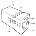
- FIG. 1A to 1C are views showing a cord retaining metal fitting according to the first embodiment of the present invention
- FIG. 1A is a perspective view
- FIG. 1B is a side view
- FIG. 1C is an exploded perspective view
- FIG. 2 is a diagram showing an example of a usage state of the cord retaining metal fitting of the present embodiment.
- the cord retaining metal fitting 1 of the present embodiment is fastened to the terminal portion of the cord 2 in order to retain the terminal of the cord 2 such as a wire rope.
- the cord retaining metal fitting 1 is fastened to the end of the cord 2 through which the hole formed in the strut 3 is inserted.
- the cord retaining metal fitting 1 of the present embodiment includes a first member 12 having a wedge-shaped portion, a second member 13 having a wedge-shaped portion, and a first member 12.
- a second member 13 and a fitting member 11 having a tubular body portion into which the cord 2 can be inserted are provided.
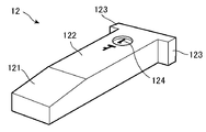
- FIG. 4A and 4B are views showing the first member 12, FIG. 4A is a perspective view, and FIG. 4B is a cross-sectional view.
- the first member 12 is a wedge-shaped member formed by the second inclined portion 122. Further, a first inclined portion 121 having an inclined angle formed larger than that of the second inclined portion 122 is provided on the tip end side thereof.
- the inclination angle of the first inclined portion 121 and the second inclined portion 122 is the relative angle of the first inclined portion 121 and the second inclined portion 122 with respect to the bottom surface of the first member 12, that is, the wedge shape.
- the first member 12 is formed to be wider than the width of the cord fastening portion 111 of the fitting member 11 and the second fitting hole 113, which will be described later.
- a flange portion 123 protruding in the width direction is formed on the rear end side of the first member 12.
- the flange portion 123 functions as an abutting portion for preventing the first member 12 from completely entering the first fitting hole 112 of the fitting member 11.
- an "upper" mark indicating that it is on the upper surface side
- a "1" mark indicating that it is a wedge to be driven into the fitting member 11 first.
- "above” is a kanji meaning above. All of them are for suppressing work mistakes and improving work efficiency.
- the mark is formed by engraving as an example here, any method may be used as long as the mark is marked on the first member 12 (hereinafter, the mark may be formed). The same applies to each mark explained in ().
- FIG. 5A and 5B are views showing the second member 13, FIG. 5A is a perspective view, and FIG. 5B is a cross-sectional view.
- the second member 13 is a member having a wedge shape formed by the inclined portion 132.
- the inclination angle of the inclined portion 132 is a relative angle of the inclined portion 132 with respect to the bottom surface of the second member 13, that is, a wedge-shaped angle.
- the width of the second member 13 is formed to be smaller than the width of the first member 12.
- a screw hole 135 is formed at the rear end of the second member 13. Further, a flange portion 133 protruding in the width direction is formed on the rear end side of the second member 13.
- the flange portion 133 functions as an abutting portion for preventing the second member 13 from completely entering the second fitting hole 113 of the fitting member 11.
- an "upper" mark (engraving) indicating that it is on the upper surface side
- a "2" mark (engraving) indicating that it is a wedge to be driven into the fitting member 11 second. Is marked. All of them are for suppressing work mistakes and improving work efficiency.
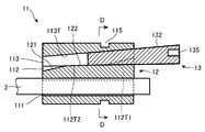
- FIG. 3A to 3D are views showing the fitting member 11, FIG. 3A is a perspective view, FIG. 3B is a side view, FIG. 3C is a cross-sectional view taken along the line AA of FIG. It is sectional drawing in line B.
- the fitting member 11 of the present embodiment is formed as a whole as a tubular body portion that receives the first member 12, the second member 13, and the cord 2. Inside the fitting member 11, three through holes communicating with each other are formed, that is, the cord fastening portion 111, the first fitting hole 112, and the second fitting hole 113.
- the cord fastening portion 111 is provided so as to communicate with the first fitting hole 112, and contact surfaces 111a and b that are in contact with the cord 2 on two surfaces are formed, thereby forming a V-shaped groove. There is.
- the function of restraining the cord 2 by the two surfaces of the V-shaped groove is the same as that described in Patent Document 1, and detailed description thereof will be omitted here.
- the first fitting hole 112 is provided so as to communicate with the cord fastening portion 111 and the second fitting hole 113, has a width larger than the width of the first member 12, and has a width larger than the width of the first member 12 inside. Is formed so that it can be inserted. As shown in FIG.
- the upper surface of the first fitting hole 112 has a second inclined surface 112T2 having an inclination angle of ⁇ 1 (relative angle with the bottom surface of the first fitting hole 112).
- the first inclined surface 112T1 having an inclination angle of ⁇ 2 (relative angle with the bottom surface of the first fitting hole 112) is provided.
- the first inclined surface 112T1 is a surface that engages with the first inclined portion 121 of the first member 12 when the first member 12 is inserted, and ⁇ 2 is abbreviated as the inclination angle of the first inclined portion 121. It is the same.
- the second inclined surface 112T2 is a surface that engages with the second inclined portion 122 of the first member 12 when the first member 12 is fitted, and ⁇ 1 is the inclined portion 122 of the second inclined portion 122. It is almost the same as the angle.
- the second fitting hole 113 is provided so as to communicate with the first fitting hole 112, has a width larger than the width of the second member 13 and smaller than the width of the first member 12, and has a second inner portion.
- the member 13 of the above is formed so as to be insertable.
- the upper surface of the second fitting hole 113 has an inclined surface 113T.
- the inclined surface 113T is a surface that engages with the inclined portion 132 of the second member 13 when the second member 13 is fitted, and the relative angle between the second inclined surface 112T2 and the inclined surface 113T is the inclined portion 132. It is almost the same as the tilt angle of.
- attachment / detachment jig engaging portions (engagement grooves in the present embodiment) 115 for attaching the wedge attachment / detachment jig described later are formed on the upper surface and the bottom surface of the fitting member 11.
- the first member 12 and the second member 12 and the second member 12 are located at positions corresponding to the first fitting hole 112 and the second fitting hole 113, respectively.
- a mark (engraving) representing each member 13 is marked. All of them are for suppressing work mistakes and improving work efficiency.
- FIGS. 6A and 6B are views showing the insertion of the first member 12, and FIG. 6A is a cross-sectional view of the central portion of the cord retaining metal fitting 1 cut along a plane parallel to the longitudinal direction and the vertical direction (hereinafter, “longitudinal section”). FIG. 6B is a cross-sectional view taken along the line CC of FIG. 6A. As shown in FIGS.
- the first member 12 when the first member 12 is inserted, the first inclined surface 112T1 of the fitting member 11 and the first inclined portion 121 of the first member 12 are engaged with each other. , The first member 12 is driven in.
- the tip portion of the first member 12 is formed thin by the first inclined portion 121, the workability of inserting the tip of the first member 12 is excellent. ..
- the first inclined portion 121 is formed to have a large inclination angle, the increase in the thickness of the wedge (that is, the fastening force) becomes large with respect to the driving distance. At the beginning of driving the wedge (first member 12), the fastening force is small, and therefore the reaction force received is also small.
- the work efficiency is improved (the driving distance is shortened) by the first inclined portion 121 having a large inclination angle.
- the dimensions of the first member 12 in the driving direction can be reduced.
- the second inclined surface 112T2 of the fitting member 11 and the second inclined portion 122 of the first member 12 engage with each other. Since the second inclined portion 122 is set to have a smaller inclination angle than the first inclined portion 121, the required striking force can be obtained even when the reaction force increases due to the progress of the driving of the wedge (first member 12). It can be suppressed to an allowable range and has excellent workability.
- the cord retaining metal fitting 1 is generated based on the wedge shape of the first member 12 when the fitting member 11 (cylindrical body portion) and the first member 12 are fitted. It is configured to generate a force for restraining the cord 2 between the first member 12 and the fitting member 11 by the pressure.
- FIG. 7A and 7B are views showing the time when the second member 13 is driven, FIG. 7A is a vertical cross-sectional view of the cord retaining metal fitting 1, and FIG. 7B is a cross-sectional view taken along the line DD of FIG. 7A.
- the second member 13 is driven while its bottom surface is in contact with the first member 12 and its upper surface is in contact with the inclined surface 113T which is the upper surface of the second fitting hole 113. That is, when the fitting member 11 (cylindrical body portion) and the second member 13 are fitted, the pressure generated based on the wedge shape of the second member 13 causes the first member 12 and the second member 13 to be fitted. It is configured to generate a force for restraining the cord 2 between the fitting member 11 and the fitting member 11.
- FIG. 8A and 8B are views showing a state in which the cord retaining metal fitting 1 is fastened to the cord 2, FIG. 8A is a vertical sectional view, and FIG. 8B is a sectional view taken along line EE of FIG. 8A. ..
- FIG. 8B when the second member 13 is driven in, the first member 12 is pushed down, and the second inclined surface 112T2 and the first member of the fitting member 11 are pushed down.
- the second inclined portion 122 of 12 is in a separated state.
- the cord retaining metal fitting 1 has two wedges, a first member 12 and a second member 13, so that the length of the metal fitting can be reduced while reducing the inclination angle of each wedge. ing.
- the amount of increase in the thickness of the wedge that produces the fastening force is a combination of the first member 12 and the second member 13, so that a high fastening force can be obtained. That is, it is compact, yet has a high fastening force, and is excellent in workability.
- the metal fitting can be miniaturized while reducing the striking force required for driving, and a high fastening force can be obtained even though the metal fitting is small. It has a very good effect.
- the case where the number of wedges is two is described as an example, but the present invention is not limited to this, and the number of wedges may be three or more.
- a V-shaped groove (contact surfaces 111a, b) is formed on the fitting member 11 (cylindrical body portion) side as an example, but the present invention is not limited to this, and the present invention is implemented.
- a contact surface may be formed on the side of the first member 12 so as to be in contact with the cord 2 on two surfaces.
- the second fitting hole 113 for driving the second member 13 is formed mainly based on the shape of the through hole of the fitting member 11 (cylindrical body portion), whereby.
- An example is that "a space portion into which a second member formed between the first member and the tubular body portion is inserted while the first member is driven into the tubular body portion" is formed.
- the present invention is not limited to this. For example, as shown in FIG. 15, by using the first member 12 ′′ ′′ having a recess on the upper surface, a space portion for driving the second member 13 may be formed.
- the inclination angles of the second inclined portion 122 of the first member 12 and the inclined portion 132 of the second member 13 are the same, but the present invention is not limited to this.
- the inclination angle of the wedge-shaped portion of the second member may be smaller than the inclination angle of the wedge-shaped portion of the first member. Since the reaction force is larger when the second member to be driven second is driven, the required striking force should be suppressed within the allowable range by reducing the inclination angle of the second member as necessary. Is what you do.
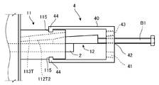
- FIGS. 9A to 9C are diagrams showing a usage state of the wedge attachment / detachment jig (drawing jig) of the present embodiment
- FIG. 9A is an explanatory view showing a state in which the first member 12 is driven
- FIG. 9B is a diagram showing a state in which the first member 12 is driven.
- FIG. 9C is an explanatory view showing a state in which the second member 13 is pulled out.
- the wedge attachment / detachment jig 4 of the present embodiment has a frame (frame portion) 40 having a substantially U-shape in side view.
- a fixed attachment portion 44 that is attached to the attachment / detachment jig engaging portion 115 of the fitting member 11 is formed on the tip side, which is the U-shaped opening side.
- the fixed mounting portion 44 of the present embodiment is formed as a convex portion that engages with the attachment / detachment jig engaging portion 115, which is an engaging groove.
- the U-shape of the frame 40 is configured so that the first member 12 and the second member 13 can be attached to and detached from the fitting member 11 in the internal space of the fitting member 11 in a state of being attached to the fitting member 11. To.
- a bolt insertion hole 41, a first bolt hole 42, and a second bolt hole 43 are formed on the back surface, which is the U-shaped closing side.
- the first bolt hole 42 is a screw hole into which the first bolt member B1 for pushing the first member 12 is screwed. As shown in FIG. 9A, the tip of the first bolt member B1 screwed into the bolt hole 42 abuts on the rear end of the first member 12, and the first bolt member B1 It is configured to be substantially parallel to the driving traveling direction of the first member 12.
- the second bolt hole 43 is a screw hole into which a second bolt member (same as the first bolt member B1 in the present embodiment) for pushing the second member 13 is screwed. As shown in FIG.
- the bolt insertion hole 41 is a bolt insertion hole through which the bolt member B2 that engages with the screw hole 135 at the rear end of the second member 13 is inserted.
- the bolt insertion hole 41 is not a screw hole screwed with the bolt member B2, but a hole through which the bolt member B2 is slidably inserted. As shown in FIG. 9C, the bolt insertion hole 41 is configured such that the bolt member B2 is substantially parallel to the drawing traveling direction of the second member 13.
- the wedge attachment / detachment jig 4 is attached to the cord retaining metal fitting 1 by attaching the fixed attachment portion 44 to the attachment / detachment jig engagement portion 115 of the fitting member 11. Then, the first member 12 is driven by screwing the first bolt member B1 screwed into the first bolt hole 42.
- the second bolt member 13 is screwed into the second bolt hole 43 (in the present embodiment, the same as the first bolt member B1). Is done by screwing in.
- the second bolt member used for driving is not screwed into the screw hole 135 at the rear end of the second member 13, but simply abuts at the rear end of the second member 13. , The second member 13 is pushed in.
- the first member 12 and the second member 13 are driven in, and the cord retaining metal fitting 1 is fastened to the cord 2.
- the wedge attachment / detachment jig 4 When removing the cord retaining metal fitting 1, the wedge attachment / detachment jig 4 is turned upside down and attached to the cord retaining metal fitting 1, so that the bolt insertion hole 41 becomes a screw hole at the rear end of the second member 13. Arrange so as to face 135. As shown in FIG. 9C, the bolt member B2 is inserted into the bolt insertion hole 41, and the small-diameter screw portion at the tip of the bolt member B2 is screwed into the screw hole 135 at the rear end of the second member 13. In this state, when the nut N1 is screwed in, the nut N1 comes into contact with the frame 40, and when the nut N1 is further tightened, the bolt member B2 is relatively pulled out.
- the direction in which the bolt member B2 tries to rotate due to the force received when the nut N1 is tightened is the rotation direction in which the small-diameter screw portion of the bolt member B2 is screwed into the screw hole 135. Therefore, when the nut N1 is tightened, the bolt member B2 and the second member 13 are not disengaged.
- the wedges (first member 12 and second member 13) can be driven and pulled out by tightening bolts and nuts.
- Bolts and nuts can be tightened easily and efficiently by using an impact wrench or the like.
- the second member 13 has been described as being pulled out by using the wedge attaching / detaching jig 4, but the first member 12 may be pulled out by using the wedge attaching / detaching jig.
- the second bolt hole 43 used when driving the second member 13 and the bolt insertion hole 41 used when pulling out are separately formed, and the wedge attachment / detachment jig 4 is turned upside down.
- the one to be used is taken as an example, but both may be shared.
- a bolt member B2 having a size smaller than that of the first bolt member B1 the bolt member B2 can be inserted into the second bolt hole 43 without being screwed.
- the present embodiment has been described as a wedge attachment / detachment jig used for the cord retaining metal fitting 1 of the first embodiment, the present invention is not limited to this, and the concept of the jig described above is an arbitrary drawing.
- the pull-out mechanism corresponding to the frame, bolt member, and nut in this embodiment
- the pull-out object is pulled out by the rotation of the screw mechanism such as tightening the nut, as in the concept described above.
- the pull-out mechanism can employ any structure that allows the distance between the engaging portion and the portion in which the pull-out object is embedded to be widened based on the screw mechanism.
- the extraction mechanism (frame) is attached to the portion (fitting member) in which the extraction target is embedded, but the extraction mechanism is necessarily the portion in which the extraction target is embedded.
- the frame 40 has a structure that abuts on the support column 3, whereby the engaging portion (bolt member) increases the distance from the embedded portion (fitting member). It may have a structure that supports the nut so that the nut can be pulled out, that is, a structure that supports the nut against the pulling force generated when the nut is tightened.
- FIG. 10A to 10C and FIG. 11 show the cord retaining metal fitting of the third embodiment and the wedge attachment / detachment jig corresponding thereto.
- FIG. 10A is a cross-sectional view showing a part of the cord retaining metal fitting 1'of the present embodiment
- FIG. 10B is a top view.
- FIG. 10C is a diagram showing a state in which the wedge attachment / detachment jig 4'of the present embodiment is used for the cord retaining metal fitting 1'
- FIG. 11 is a front view showing the wedge attachment / detachment jig 4'.
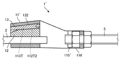
- the cord retaining metal fitting 1' has a retaining portion 116 that is fastened to the retaining screw 5 on the rear side of the fitting member 11', so that the retaining screw 5 and the cord 2 can be fastened to each other. It is a thing.
- the retaining portion 116 is formed in a substantially U shape in a top view (FIG. 10B) by extending both side surfaces of the tubular body portion rearward and connecting the rear ends with the rear end surfaces.
- the rear end surface has a configuration in which the retaining screw 5 is inserted and fixed with a nut.
- An attachment / detachment jig engagement portion (here, an engagement groove) 115'for attaching the wedge attachment / detachment jig 4'is formed on the inner surface of the portion of the retaining portion 116 in which both side surfaces of the tubular body portion are extended rearward. Has been done.
- the wedge attachment / detachment jig 4' is composed of a frame of a plate-shaped member, and has a first bolt hole 42'used when driving the first member 12 and a first bolt hole 42'used when driving the second member 13. No. 2 bolt hole 43'is formed. As described above, the second bolt hole 43'of this embodiment is shared with the bolt insertion hole through which the bolt member used when pulling out the second member 13 is inserted. As shown in FIG. 11, on the lower end side of the wedge attachment / detachment jig 4', a fixed attachment portion 44'that is attached to the attachment / detachment jig engagement portion 115'of the fitting member 11'is formed in a bifurcated shape. Has been done.
- the wedge attachment / detachment jig 4' is fitted by sliding the wedge attachment / detachment jig 4'from above and fitting the fixed attachment portion 44'to the attachment / detachment jig engagement portion 115'of the fitting member 11'. Attach to member 11'.
- the first bolt hole 42'and the second bolt hole 43' are arranged at positions facing the first member 12 and the second member 13, respectively, and the first bolt hole 42'is arranged as described in the second embodiment.
- the member 12 and the second member 13 can be attached and detached.
- FIG. 12A to 12C are views showing the cord retaining metal fittings of the fourth embodiment
- FIG. 12A is a vertical sectional view
- FIG. 12B is a sectional view taken along line FF of FIG. 12A
- FIG. 12C is a completed driving. It is a cross-sectional view in the state of being.
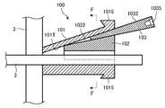
- the cord retaining metal fitting 100 of the present embodiment includes a first member 102 having a wedge-shaped portion, a second member 103 having a wedge-shaped portion, a first member 102, and a first member.
- the member 103 of 2 and the fitting member 101 having a tubular body portion into which the cord 2 can be inserted are provided. Due to the pressure generated when the first member 102 and the second member 103 are driven into the tubular body portion of the fitting member 101 together with the cord 2, the fitting member 101, the first member 102, and the second member 102 are second. A frictional force is generated between each of the member 103 and the cord body 2, whereby the cord retaining metal fitting 100 is fastened to the cord body 2.
- the first member 102 is a member having a wedge shape formed by the inclined portion 1022. On the bottom surface side of the first member 102, a contact surface that is in contact with the cord 2 on two surfaces is formed, thereby forming a V-shaped groove shape.
- the function of restraining the cord 2 by the two surfaces of the V-shaped groove formed in the wedge is the same as that described in Patent Document 1, and detailed description thereof will be omitted here.
- the second member 103 is a member having a wedge shape formed by the inclined portion 1032.
- the wedge shape corresponds to a wedge-shaped space formed between the inclined portion 1022 of the first member 102 and the inclined surface 101T of the tubular body portion of the fitting member 101.
- the inclination angle of the wedge-shaped portion of the second member 103 is smaller than the inclination angle of the inclined surface 101T of the tubular body portion of the fitting member 101.
- a screw hole 1035 is formed at the rear end of the second member 13.
- the fitting member 101 has a tubular body portion into which the first member 102, the second member 103, and the cord 2 can be inserted into the fitting member 101.
- the upper surface of the inner surface of the tubular body portion has an inclined surface 101T.
- the inclined surface 101T has an inclination angle larger than that of the inclined portion 1022 of the first member 102, and therefore the inclined portion 1022 and the tubular body portion of the first member 102 are inclined.
- a wedge-shaped space is formed with the surface 101T.
- the space portion is "a space portion into which a second member 103 formed between the first member 102 and the tubular body portion is inserted while the first member 102 is driven into the tubular body portion". Is. As shown in FIGS.
- a recess 1011 is formed on the inner surface of the tubular body portion at a position facing the V-shaped tip portion of the first member 102. As shown in FIG. 12C, the recess 1011 has a V-shape of the first member 102 when the first member 102 is lowered by driving the first member 102 and the second member 103. It is a relief part that prevents the tip part of the. Further, on the upper surface and the bottom surface of the fitting member 101, attachment / detachment jig engaging portions 1015 for attaching the wedge attachment / detachment jig are formed.
- FIG. 13A and 13B are views showing a state in which the wedge attachment / detachment jig 4 ′′ of the present embodiment is used for the cord retaining metal fitting 100
- FIG. 13A is a view showing a state in which the second member 103 is driven.
- FIG. 13B is a diagram showing a state in which the second member 103 is pulled out.
- the wedge attachment / detachment jig 4 ′′ has a frame 40 ′′ having a substantially U-shaped shape in a side view.
- a fixed attachment portion 44 ′′ that is attached to the attachment / detachment jig engaging portion 1015 of the fitting member 101 is formed on the tip side, which is the U-shaped opening side.
- the U-shape of the frame 40 ′′ is attached to the fitting member 101 so that the first member 102 and the second member 103 can be attached to and detached from the fitting member 101 in the internal space thereof. It is composed.
- a bolt hole 43 ′′ for screwing the bolt member B3 used when driving the second member 103 is formed on the back surface on the U-shaped closing side.
- the bolt hole 43 ′′ can be inserted through the bolt member B4 used when pulling out the second member 103 without screwing. Since the driving and pulling work of the second member 103 has the same concept as that of the second embodiment, detailed description thereof will be omitted here.
- the metal fitting can be miniaturized while reducing the striking force required for driving, and a high fastening force can be obtained even though the metal fitting is small. It has a very good effect of being able to.
- the wedge body (first member) is provided with a V-shaped groove, as described in Patent Document 1
- the wedge body and the cord body are integrally formed when tension is applied to the cord body. The action of penetrating deeper into the tubular body can be obtained, and a high fastening force can be obtained.
- the first member 102 also has a wedge shape as an example, but the first member does not necessarily have to have a wedge shape.
- the first member 102'does not have a wedge shape, it is possible to obtain an action effect substantially equivalent to that of the cord retaining metal fitting 100 described in the present embodiment.
Landscapes
- Engineering & Computer Science (AREA)
- General Engineering & Computer Science (AREA)
- Mechanical Engineering (AREA)
- Clamps And Clips (AREA)
- Suspension Of Electric Lines Or Cables (AREA)
Priority Applications (1)
| Application Number | Priority Date | Filing Date | Title |
|---|---|---|---|
| JP2021554812A JP7472161B2 (ja) | 2019-11-07 | 2020-06-12 | 索体引留金具、くさび着脱治具、及び、引抜治具 |
Applications Claiming Priority (2)
| Application Number | Priority Date | Filing Date | Title |
|---|---|---|---|
| JP2019-202219 | 2019-11-07 | ||
| JP2019202219 | 2019-11-07 |
Publications (1)
| Publication Number | Publication Date |
|---|---|
| WO2021090529A1 true WO2021090529A1 (ja) | 2021-05-14 |
Family
ID=75848318
Family Applications (1)
| Application Number | Title | Priority Date | Filing Date |
|---|---|---|---|
| PCT/JP2020/023207 Ceased WO2021090529A1 (ja) | 2019-11-07 | 2020-06-12 | 索体引留金具、くさび着脱治具、及び、引抜治具 |
Country Status (3)
| Country | Link |
|---|---|
| JP (1) | JP7472161B2 (https=) |
| TW (1) | TWI748711B (https=) |
| WO (1) | WO2021090529A1 (https=) |
Cited By (1)
| Publication number | Priority date | Publication date | Assignee | Title |
|---|---|---|---|---|
| JP2024030837A (ja) * | 2022-08-25 | 2024-03-07 | 三菱電機ビルソリューションズ株式会社 | エレベータ昇降路内配線装置 |
Citations (5)
| Publication number | Priority date | Publication date | Assignee | Title |
|---|---|---|---|---|
| JPS4885080U (https=) * | 1972-01-18 | 1973-10-16 | ||
| JPS5016236Y1 (https=) * | 1970-10-21 | 1975-05-20 | ||
| JP2000505535A (ja) * | 1996-03-23 | 2000-05-09 | グリップル・リミテッド | ワイヤー等を締付けるための装置 |
| JP2004520508A (ja) * | 2001-02-14 | 2004-07-08 | キム,ヨン−グン | 鉄筋継手具 |
| JP2008245373A (ja) * | 2007-03-26 | 2008-10-09 | Tokyo Seiko Co Ltd | 条体の楔式クランプ |
Family Cites Families (2)
| Publication number | Priority date | Publication date | Assignee | Title |
|---|---|---|---|---|
| EP1757819A4 (en) * | 2004-04-07 | 2011-03-30 | Sumitomo Sei Steel Wire Corp | EVEN ARRANGEMENT TOOL FOR A SPREAD ANCHOR |
| JP6342563B1 (ja) * | 2017-10-12 | 2018-06-13 | 東京製綱株式会社 | くさびクランプ及び鋼線 |
-
2020
- 2020-06-12 WO PCT/JP2020/023207 patent/WO2021090529A1/ja not_active Ceased
- 2020-06-12 JP JP2021554812A patent/JP7472161B2/ja active Active
- 2020-10-27 TW TW109137188A patent/TWI748711B/zh not_active IP Right Cessation
Patent Citations (5)
| Publication number | Priority date | Publication date | Assignee | Title |
|---|---|---|---|---|
| JPS5016236Y1 (https=) * | 1970-10-21 | 1975-05-20 | ||
| JPS4885080U (https=) * | 1972-01-18 | 1973-10-16 | ||
| JP2000505535A (ja) * | 1996-03-23 | 2000-05-09 | グリップル・リミテッド | ワイヤー等を締付けるための装置 |
| JP2004520508A (ja) * | 2001-02-14 | 2004-07-08 | キム,ヨン−グン | 鉄筋継手具 |
| JP2008245373A (ja) * | 2007-03-26 | 2008-10-09 | Tokyo Seiko Co Ltd | 条体の楔式クランプ |
Cited By (1)
| Publication number | Priority date | Publication date | Assignee | Title |
|---|---|---|---|---|
| JP2024030837A (ja) * | 2022-08-25 | 2024-03-07 | 三菱電機ビルソリューションズ株式会社 | エレベータ昇降路内配線装置 |
Also Published As
| Publication number | Publication date |
|---|---|
| TW202118952A (zh) | 2021-05-16 |
| TWI748711B (zh) | 2021-12-01 |
| JPWO2021090529A1 (https=) | 2021-05-14 |
| JP7472161B2 (ja) | 2024-04-22 |
Similar Documents
| Publication | Publication Date | Title |
|---|---|---|
| WO2021090529A1 (ja) | 索体引留金具、くさび着脱治具、及び、引抜治具 | |
| JP2009144809A (ja) | 管体継ぎ手用クランプ | |
| JP5411593B2 (ja) | ワイヤー張設具 | |
| JP2010106599A (ja) | 接合金具の取付構造 | |
| JP4630883B2 (ja) | 条体の楔式クランプ | |
| JP6496305B2 (ja) | アンカーボルト | |
| JP2013014932A (ja) | 建築用木材の継合構造 | |
| JP2009167777A (ja) | 型枠パネル及び連結金具と除去金具 | |
| JP4812815B2 (ja) | 木造建築用の軸組接合具 | |
| JP5248817B2 (ja) | 鉄筋とセパレータの接合金具 | |
| JP2016080113A (ja) | 連結部材及びそれを備えた連結構造 | |
| JP6171192B2 (ja) | アンカーボルト位置決め工具 | |
| JP2009115175A (ja) | 物品固定構造 | |
| JP2009092229A (ja) | 螺具の補助材 | |
| JP7669298B2 (ja) | 索体引留金具 | |
| JP4899017B2 (ja) | 部材の結合構造 | |
| KR200435520Y1 (ko) | 트레이 클램프 | |
| JP2025151682A (ja) | 索体引留金具 | |
| JP4894022B2 (ja) | 部材連結装置 | |
| JP2020122350A (ja) | 外壁材受け具 | |
| JP7156707B2 (ja) | 仮設足場などの取付け金物 | |
| JP2011140817A (ja) | 建物用庇の取付部構造 | |
| JP2009167762A (ja) | 接合金具 | |
| JP4584892B2 (ja) | 配線ボックス | |
| JP2005200859A (ja) | 接合ピン及びこの接合ピンを用いた接合構造 |
Legal Events
| Date | Code | Title | Description |
|---|---|---|---|
| 121 | Ep: the epo has been informed by wipo that ep was designated in this application |
Ref document number: 20884982 Country of ref document: EP Kind code of ref document: A1 |
|
| ENP | Entry into the national phase |
Ref document number: 2021554812 Country of ref document: JP Kind code of ref document: A |
|
| NENP | Non-entry into the national phase |
Ref country code: DE |
|
| 122 | Ep: pct application non-entry in european phase |
Ref document number: 20884982 Country of ref document: EP Kind code of ref document: A1 |