WO2021090391A1 - 空気調和装置の室外機、及び、空気調和装置の室外機の組み立て方法 - Google Patents
空気調和装置の室外機、及び、空気調和装置の室外機の組み立て方法 Download PDFInfo
- Publication number
- WO2021090391A1 WO2021090391A1 PCT/JP2019/043429 JP2019043429W WO2021090391A1 WO 2021090391 A1 WO2021090391 A1 WO 2021090391A1 JP 2019043429 W JP2019043429 W JP 2019043429W WO 2021090391 A1 WO2021090391 A1 WO 2021090391A1
- Authority
- WO
- WIPO (PCT)
- Prior art keywords
- oil separator
- outdoor unit
- air conditioner
- partition plate
- bed
- Prior art date
- Legal status (The legal status is an assumption and is not a legal conclusion. Google has not performed a legal analysis and makes no representation as to the accuracy of the status listed.)
- Ceased
Links
Images





Classifications
-
- F—MECHANICAL ENGINEERING; LIGHTING; HEATING; WEAPONS; BLASTING
- F24—HEATING; RANGES; VENTILATING
- F24F—AIR-CONDITIONING; AIR-HUMIDIFICATION; VENTILATION; USE OF AIR CURRENTS FOR SCREENING
- F24F1/00—Room units for air-conditioning, e.g. separate or self-contained units or units receiving primary air from a central station
- F24F1/06—Separate outdoor units, e.g. outdoor unit to be linked to a separate room comprising a compressor and a heat exchanger
- F24F1/46—Component arrangements in separate outdoor units
-
- F—MECHANICAL ENGINEERING; LIGHTING; HEATING; WEAPONS; BLASTING
- F24—HEATING; RANGES; VENTILATING
- F24F—AIR-CONDITIONING; AIR-HUMIDIFICATION; VENTILATION; USE OF AIR CURRENTS FOR SCREENING
- F24F1/00—Room units for air-conditioning, e.g. separate or self-contained units or units receiving primary air from a central station
- F24F1/06—Separate outdoor units, e.g. outdoor unit to be linked to a separate room comprising a compressor and a heat exchanger
- F24F1/56—Casing or covers of separate outdoor units, e.g. fan guards
Definitions
- the present invention relates to an outdoor unit of an air conditioner having a structure for fixing an oil separator to a partition plate using auxiliary parts, and a method of assembling an outdoor unit of an air conditioner.
- the inside of the outdoor unit of the air conditioner is divided into a blower room and a machine room by a partition plate.
- the blower room is equipped with a blower and a heat exchanger, and the machine room contains electronic parts and piping assemblies. It is equipped.
- a component called an accumulator that stores refrigerant is connected to the assembly of piping in the machine room.
- an accumulator is arranged above the compressor in order to reduce the size of the machine room.
- the accumulator is fixed to the partition plate above the compressor.
- Patent Document 1 proposes that a reinforcing plate is attached to a partition plate and an accumulator is directly attached to the reinforcing plate.
- the present invention has been made to solve the above problems, and is an outdoor unit of an air conditioner capable of improving workability when attaching an oil separator to a partition plate, and an air conditioner. This is to obtain a method for assembling the outdoor unit.
- the outdoor unit of the air conditioner according to the present invention includes a blower room, a machine room, and a partition plate that separates the blower room and the machine room, and the compressor and the oil separator are housed in the machine room.
- the oil separator is fixed to the partition plate by an auxiliary part, and the auxiliary part is detachably attached to the leg portion fixed to the partition plate and the leg portion.
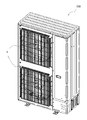
- FIG. 1 is a perspective view of the appearance of the outdoor unit 100 of the air conditioner according to the present embodiment.
- FIG. 2 is a perspective view of the inside of the outdoor unit 100 of the air conditioner according to the present embodiment.
- the outdoor unit 100 of the air conditioner has, for example, two blowers 4 provided side by side in the vertical direction.
- the inside of the outdoor unit 100 of the air conditioner is divided into a blower room 2 and a machine room 3 by a partition plate 1.
- a blower 4 and a heat exchanger 5 are arranged in the blower room 2.
- a compressor 6, an electric component box 7, and an oil separator assembly 8 are arranged.
- the oil separator assembly 8 is configured by connecting a plurality of pipes to the oil separator 8a.
- the oil separator 8a has a cylindrical shape and has a function of separating oil from the gas refrigerant discharged from the compressor 6.
- the oil separator assembly 8 is arranged above the compressor 6 and is connected to the discharge pipe 6a of the compressor 6.
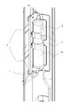
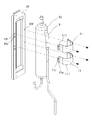
- FIG. 3 is a perspective view showing a state in which the oil separator assembly 8 according to the embodiment is attached to the partition plate 1. As shown in FIG. 3, the oil separator assembly 8 is attached to the partition plate 1 by an auxiliary part composed of a leg portion 9, a bed portion 10, and a band portion 11.
- the bed portion 10 is fixed to the leg portion 9 fixed to the partition plate 1, and the oil separator assembly 8 is supported by the bed portion 10, so that the partition plate 1 is formed. It is attached. Further, the oil separator assembly 8 is fixed to the bed portion 10 by the band portion 11.
- FIG. 4 is a detailed view of the leg portion 9 according to the embodiment.
- FIG. 5 is a detailed view of the leg portion 9 according to the embodiment, and is a view of the leg portion 9 of FIG. 4 as viewed from the opposite side.
- the leg portion 9 includes a flat surface portion 91 located at both ends in the longitudinal direction of the leg portion 9, a central portion 92 located between the two flat surface portions 91, and a flat surface portion 91. It is composed of a connecting portion 93 that connects to the central portion 92.
- the connecting portion 93 extends in a direction intersecting the flat surface portion 91 and the central portion 92, and connects the flat surface portion 91 extending in parallel with each other and the central portion 92 in a stepped shape.
- a total of three alignment holes 9a are formed in the flat surfaces 91 at both ends.
- the alignment hole 9a is provided to align the leg portion 9 with the mounting position of the partition plate 1.
- one alignment hole 9a is formed in one of the flat surface portions 91 at both ends, and two are formed in the other flat surface portion 91.
- the two alignment holes 9a formed in the other flat surface portion 91 are formed, for example, in different dimensions from each other.
- the three alignment holes 9a provided in the flat surfaces 91 at both ends clarify the vertical and horizontal directions of the legs 9 and facilitate keeping the height positions of the flat portions 91 at both ends horizontal.
- the central portion 92 and the connecting portion 93 of the leg portion 9 have a leg flange 9b formed by bending the upper edge and the lower edge.
- the rigidity of the leg portion 9 can be increased by forming the leg flange 9b extending in the direction intersecting the flat plate surfaces of the central portion 92 and the connecting portion 93.
- a screw hole 9c is formed in the central portion 92 of the leg portion 9.
- the screw hole 9c is a hole into which a screw for fixing the bed portion 10 is inserted into the leg portion 9.
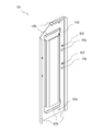
- FIG. 6 is a detailed view of the bed portion 10 according to the embodiment.
- FIG. 7 is a detailed view of the bed portion 10 according to the embodiment, and is a view of the bed portion 10 of FIG. 6 as viewed from the opposite side.
- the bed portion 10 has a recessed portion 10a formed in the center.
- a flat plate surface is provided on the outer periphery of the recessed portion 10a.
- the flat plate-shaped region on the outer circumference of the recessed portion 10a is referred to as the outer peripheral portion 101.
- a screw hole 10e is provided on the outer peripheral portion 101 of the bed portion 10 in the lateral direction.
- the bed portion 10 is detachably attached to the leg portion 9 with the outer peripheral portion 101 of the flat surface in contact with the central portion 92 of the leg portion 9 by a screw inserted into the screw hole 10e of the bed portion 10.
- the bed portion 10 has a bed portion flange 10b extending from the edge of the outer peripheral portion 101 in a direction intersecting with the outer peripheral portion 101.
- the bed flange 10b is formed by bending the edge of the outer peripheral portion 101, for example.
- the bed portion flange 10b is formed of, for example, a member provided so as to protrude from the bed portion 10.
- the bed portion flange 10b of the bed portion 10 is provided to hook the bed portion 10 to the leg portion flange 9b of the leg portion 9 when the bed portion 10 is attached to the leg portion 9. Therefore, the bed flange 10b has a shape that follows the shape of the leg flange 9b of the leg 9.
- the recessed portion 10a of the bed portion 10 has a contour having a shape extending along the longitudinal direction of the bed portion 10, and is recessed in the same direction as the extending direction of the bed portion flange 10b.
- the oil separator 8a of the oil separator assembly 8 is fitted in the recessed portion 10a, whereby the oil separator assembly 8 is supported by the bed portion 10.
- a cushioning material 10d is attached to the inner surface of the recessed portion 10a.
- the cushioning material 10d for example, a sponge or the like can be used.
- a screw hole 10f and a quadrangular square hole 10c are formed in the outer peripheral portion 101 of the bed portion 10 along the longitudinal direction of the bed portion 10.
- the square hole 10c of the bed portion 10 is formed to align the band portion 11 with the mounting position.
- the screw hole 10f of the bed portion 10 is formed to fix the band portion 11 to the bed portion 10.
- FIG. 8 is a detailed view of the band portion 11 according to the embodiment.
- FIG. 9 is a detailed view of the band portion 11 according to the embodiment, and is a view of the band portion 11 of FIG. 8 as viewed from the opposite side.
- the band portion 11 is composed of a curved surface portion 111 at the center and flat surface portions 112 on both sides of the curved surface portion 111.
- the curved surface portion 111 has a curved surface shape along the outer peripheral surface of the oil separator 8a.
- a cushioning material 11b is attached to the inside of the curved surface portion 111. Since the curved surface portion 111 of the band portion 11 serves as a contact surface with the oil separator 8a, the gap between the band portion 11 and the oil separator 8a can be reduced by providing the cushioning material 11b. As a result, the oil separator 8a is strongly pressed against the band portion 11, so that the transmission of vibration is suppressed and abnormal noise is reduced.
- a claw portion 11a projecting downward from the lower end is formed on one of the flat surface portions 112 on both sides of the curved surface portion 111.
- the claw portion 11a is inserted into the square hole 10c of the bed portion 10, and the band portion 11 and the bed portion 10 are aligned with each other.
- Screw holes 11c are formed in each of the flat surface portions 112 on both sides of the curved surface portion 111.
- the screw hole 11c of the band portion 11 is screwed to the screw hole 10e of the bed portion 10, and the band portion 11 is fixed to the bed portion 10.
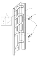
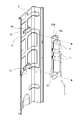
- FIG. 10 is a perspective view showing a step of fixing the leg portion 9 according to the embodiment to the partition plate 1.
- the leg portion 9 in the step of fixing the leg portion 9 to the partition plate 1, the leg portion 9 is arranged so that the longitudinal direction of the leg portion 9 is along the width direction of the partition plate 1.
- the partition plate 1 and the leg portion 9 are aligned so that the alignment hole 9a of the leg portion 9 is fitted into the embossed portion 1a formed on the partition plate 1.
- the flat surface portions 91 are fixed to the partition plate 1 by spot welding in a state where the flat surface portions 91 at both ends of the leg portion 9 are in contact with the partition plate 1.
- the leg portion 9 is fixed to the partition plate 1.
- the embossed portion 1a has a shape in which a part of the partition plate 1 projects from the blower chamber 2 toward the machine chamber 3.
- the embossed portion 1a is formed by, for example, embossing.
- the legs 9 are attached to the partition plate 1 at two locations in the vertical direction.
- the legs 9 may be provided at two or more locations in the vertical direction of the partition plate 1. It is preferable that the number of legs 9 is two or more because the load is dispersed and the load applied to one leg 9 is suppressed. Further, since the leg portion 9 is formed with three alignment holes 9a, the mounting positions of the partition plate 1 in the vertical direction and the horizontal direction become more accurate.
- FIG. 11 is a perspective view showing a step of fixing the oil separator assembly 8, the bed portion 10, and the band portion 11 according to the embodiment.
- the oil separator 8a is placed on the recessed portion 10a of the bed portion 10.
- the oil separator assembly 8 is fixed to the bed portion 10 by the band portion 11. Specifically, the curved surface portion 111 of the band portion 11 is aligned with the outer peripheral surface of the oil separator 8a, and the flat surface portion 112 of the band portion 11 is aligned with the outer peripheral portion 101 of the bed portion 10. Then, the claw portion 11a of the band portion 11 is inserted into the square hole 10c of the bed portion 10 to position the band portion 11, and the band portion 112 is in contact with the outer peripheral portion 101 of the bed portion 10 and the flat portion 112 of the band portion 11. The screw hole 11c of the portion 11 and the screw hole 10e of the bed portion 10 are screwed together.
- the oil separator assembly 8 is fixed to the bed portion 10 by the band portion 11. Similar to the leg portion 9, the band portion 11 is attached at two locations in the vertical direction of the oil separator 8a, but the band portion 11 may be provided at two or more locations in the vertical direction of the oil separator 8a. It is preferable that the number of band portions 11 is two or more because the oil separator 8a is more firmly fixed.
- FIG. 12 is a perspective view showing a process of attaching the oil separator assembly 8 according to the embodiment to the partition plate 1.
- the bed portion flange 10b of the bed portion 10 to which the oil separator assembly 8 is fixed by the band portion 11 is fixed to the partition plate 1.
- Hook on the leg flange 9b of the leg 9 is fixed to the partition plate 1.
- the piping of the oil separator assembly 8 and the discharge piping 6a of the compressor 6 are connected to complete the assembly of the outdoor unit 100 of the air conditioner.
- the oil separator assembly 8 is mounted on the legs 9 fixed to the partition plate 1 and the oil separator assembly 8. It is fixed to the partition plate 1 by an auxiliary part having a bed portion 10. Therefore, even if the weight of the oil separator assembly 8 increases, the partition plate 1 can be reinforced by the auxiliary member to ensure the rigidity of the partition plate 1. Further, since the leg portion 9 of the auxiliary part fixed to the partition plate 1 and the bed portion 10 on which the oil separator assembly 8 is placed can be attached and detached, the work of attaching the oil separator assembly 8 to the partition plate 1 becomes easier.
- the oil separator assembly 8 is fixed to the partition plate 1, it is not necessary for the operator to support the oil separator assembly 8 when connecting the compressor 6 to the oil separator assembly 8, and the connection work is easy. It becomes. Further, since the leg portion 9 and the bed portion 10 which are auxiliary parts are interposed between the oil separator assembly 8 and the partition plate 1, the oil separator assembly 8 is directly fixed to the partition plate 1. It is possible to suppress the vibration transmitted to the partition plate 1 as compared with the above. As a result, the vibration of the pipe during the operation of the outdoor unit 100 is transmitted to the oil separator assembly 8, and the vibration of the pipe connected to the oil separator assembly 8 is suppressed.
- the oil separator assembly 8 is integrated with the bed portion 10 by the band portion 11, the work of attaching the oil separator assembly 8 to the partition plate 1 becomes easy.
- the alignment between the leg portion 9 and the partition plate 1 becomes easy.
- the rigidity of the leg portion 9 and the bed portion 10 can be increased by the leg flange 9b of the leg portion 9 and the bed portion flange 10b of the bed portion 10.
- the leg portion 9 and the bed portion 10 can be easily aligned and fixed.
- leg portion 9 in the state where the oil separator assembly 8 is not attached is easy to handle, it is easy to attach it to the partition plate 1.
- the leg portion 9 and the partition plate 1 are securely fixed.
- the bed portion 10 is fixed to the leg portion 9 with a screw, the work of attaching the oil separator assembly 8 to the partition plate 1 becomes easy.
- the gap between the bed portion 10 and the oil separator assembly 8 can be reduced, so that the bed portion 10 and the oil separator assembly 8 are less likely to be displaced due to vibration or the like. , Noise can also be reduced.
- the cushioning material 11b in the band portion 11 the gap between the band portion 11 and the oil separator assembly 8 can be reduced, so that noise can be reduced.
- the oil separator 8a is fitted into the recessed portion 10a of the bed portion 10, the posture of the oil separator 8a placed on the bed portion 10 is stable.
Landscapes
- Engineering & Computer Science (AREA)
- Chemical & Material Sciences (AREA)
- Combustion & Propulsion (AREA)
- Mechanical Engineering (AREA)
- General Engineering & Computer Science (AREA)
- Applications Or Details Of Rotary Compressors (AREA)
- Other Air-Conditioning Systems (AREA)
Priority Applications (5)
| Application Number | Priority Date | Filing Date | Title |
|---|---|---|---|
| US17/637,215 US12025325B2 (en) | 2019-11-06 | 2019-11-06 | Outdoor unit for air-conditioning apparatus and method for assembling outdoor unit for air-conditioning apparatus |
| JP2021554459A JPWO2021090391A1 (https=) | 2019-11-06 | 2019-11-06 | |
| CN201980101432.2A CN114599920A (zh) | 2019-11-06 | 2019-11-06 | 空调装置的室外机以及空调装置的室外机的组装方法 |
| PCT/JP2019/043429 WO2021090391A1 (ja) | 2019-11-06 | 2019-11-06 | 空気調和装置の室外機、及び、空気調和装置の室外機の組み立て方法 |
| DE112019007872.0T DE112019007872T5 (de) | 2019-11-06 | 2019-11-06 | Außeneinheit für eine Klimaanlage und Verfahren zum Zusammenbauen einer Außeneinheit für eine Klimaanlage |
Applications Claiming Priority (1)
| Application Number | Priority Date | Filing Date | Title |
|---|---|---|---|
| PCT/JP2019/043429 WO2021090391A1 (ja) | 2019-11-06 | 2019-11-06 | 空気調和装置の室外機、及び、空気調和装置の室外機の組み立て方法 |
Publications (1)
| Publication Number | Publication Date |
|---|---|
| WO2021090391A1 true WO2021090391A1 (ja) | 2021-05-14 |
Family
ID=75848829
Family Applications (1)
| Application Number | Title | Priority Date | Filing Date |
|---|---|---|---|
| PCT/JP2019/043429 Ceased WO2021090391A1 (ja) | 2019-11-06 | 2019-11-06 | 空気調和装置の室外機、及び、空気調和装置の室外機の組み立て方法 |
Country Status (5)
| Country | Link |
|---|---|
| US (1) | US12025325B2 (https=) |
| JP (1) | JPWO2021090391A1 (https=) |
| CN (1) | CN114599920A (https=) |
| DE (1) | DE112019007872T5 (https=) |
| WO (1) | WO2021090391A1 (https=) |
Families Citing this family (3)
| Publication number | Priority date | Publication date | Assignee | Title |
|---|---|---|---|---|
| USD1095781S1 (en) | 2023-06-30 | 2025-09-30 | Rheem Manufacturing Company | Outdoor HVAC unit |
| USD1095780S1 (en) | 2023-06-30 | 2025-09-30 | Rheem Manufacturing Company | Outdoor HVAC unit |
| USD1078003S1 (en) * | 2023-06-30 | 2025-06-03 | Rheem Manufacturing Company | Outdoor HVAC unit |
Citations (6)
| Publication number | Priority date | Publication date | Assignee | Title |
|---|---|---|---|---|
| JP2004270919A (ja) * | 2002-09-23 | 2004-09-30 | Tecumseh Products Co | コンプレッサの取付けブラケットと製造方法 |
| JP2008267651A (ja) * | 2007-04-18 | 2008-11-06 | Matsushita Electric Ind Co Ltd | 組立式換気扇 |
| JP2013194960A (ja) * | 2012-03-16 | 2013-09-30 | Daikin Industries Ltd | 冷凍装置の室外機 |
| CN207865564U (zh) * | 2017-12-08 | 2018-09-14 | 大金工业株式会社 | 一种空调室外机 |
| CN208846576U (zh) * | 2018-08-23 | 2019-05-10 | 宁波奥克斯电气股份有限公司 | 减震抱攀及空调机 |
| JP2019163878A (ja) * | 2018-03-19 | 2019-09-26 | 株式会社富士通ゼネラル | 空気調和機の室外機 |
Family Cites Families (12)
| Publication number | Priority date | Publication date | Assignee | Title |
|---|---|---|---|---|
| JPH10185244A (ja) * | 1996-12-20 | 1998-07-14 | Fujitsu General Ltd | 空気調和機の室外機 |
| JP2005076924A (ja) | 2003-08-29 | 2005-03-24 | Daikin Ind Ltd | 液溜容器の支持構造及びそれを備えた空気調和装置の室外ユニット |
| KR100995432B1 (ko) * | 2007-09-25 | 2010-11-18 | 산요덴키가부시키가이샤 | 공기 조화 장치의 실외 유닛 |
| JP4859801B2 (ja) | 2007-09-28 | 2012-01-25 | 三洋電機株式会社 | 空気調和装置の室外ユニット |
| JP2011112324A (ja) | 2009-11-30 | 2011-06-09 | Fujitsu General Ltd | 空気調和機の室外機 |
| CN202547029U (zh) * | 2012-04-16 | 2012-11-21 | 珠海格力电器股份有限公司 | 用于油分离器的固定装置 |
| CN104197430B (zh) * | 2014-09-17 | 2017-03-15 | 珠海格力电器股份有限公司 | 空调室外机 |
| WO2017042950A1 (ja) | 2015-09-11 | 2017-03-16 | 三菱電機株式会社 | 空気調和機の室外機 |
| JP6747105B2 (ja) * | 2016-06-30 | 2020-08-26 | 富士電機株式会社 | 配電盤の薄板パネルフレーム構造 |
| JP6732110B2 (ja) * | 2017-04-18 | 2020-07-29 | 三菱電機株式会社 | 室外機、空気調和機、及び、室外機の製造方法 |
| JP6937840B2 (ja) | 2017-11-15 | 2021-09-22 | 三菱電機株式会社 | 空気調和機の室外機 |
| CN108826514B (zh) * | 2018-08-23 | 2023-08-11 | 宁波奥克斯电气股份有限公司 | 一体式固定支架、油分气分固定组件及空调器 |
-
2019
- 2019-11-06 WO PCT/JP2019/043429 patent/WO2021090391A1/ja not_active Ceased
- 2019-11-06 CN CN201980101432.2A patent/CN114599920A/zh active Pending
- 2019-11-06 US US17/637,215 patent/US12025325B2/en active Active
- 2019-11-06 DE DE112019007872.0T patent/DE112019007872T5/de active Pending
- 2019-11-06 JP JP2021554459A patent/JPWO2021090391A1/ja active Pending
Patent Citations (6)
| Publication number | Priority date | Publication date | Assignee | Title |
|---|---|---|---|---|
| JP2004270919A (ja) * | 2002-09-23 | 2004-09-30 | Tecumseh Products Co | コンプレッサの取付けブラケットと製造方法 |
| JP2008267651A (ja) * | 2007-04-18 | 2008-11-06 | Matsushita Electric Ind Co Ltd | 組立式換気扇 |
| JP2013194960A (ja) * | 2012-03-16 | 2013-09-30 | Daikin Industries Ltd | 冷凍装置の室外機 |
| CN207865564U (zh) * | 2017-12-08 | 2018-09-14 | 大金工业株式会社 | 一种空调室外机 |
| JP2019163878A (ja) * | 2018-03-19 | 2019-09-26 | 株式会社富士通ゼネラル | 空気調和機の室外機 |
| CN208846576U (zh) * | 2018-08-23 | 2019-05-10 | 宁波奥克斯电气股份有限公司 | 减震抱攀及空调机 |
Also Published As
| Publication number | Publication date |
|---|---|
| JPWO2021090391A1 (https=) | 2021-05-14 |
| US12025325B2 (en) | 2024-07-02 |
| CN114599920A (zh) | 2022-06-07 |
| DE112019007872T5 (de) | 2022-09-01 |
| US20220299214A1 (en) | 2022-09-22 |
Similar Documents
| Publication | Publication Date | Title |
|---|---|---|
| WO2021090391A1 (ja) | 空気調和装置の室外機、及び、空気調和装置の室外機の組み立て方法 | |
| JP2007292073A (ja) | 冷却機器 | |
| JP6219763B2 (ja) | 圧縮機のワッシャー固定治具および圧縮機の固定方法 | |
| JP2022147641A (ja) | 電動圧縮機 | |
| JP2019140803A (ja) | 回転電機ユニット | |
| US20150000867A1 (en) | Compression apparatus and cooler unit | |
| JP2021067006A (ja) | 振れ止め装置 | |
| WO2016103447A1 (ja) | 室外機 | |
| JPWO2021090391A5 (https=) | ||
| JP2016090166A (ja) | 冷凍装置 | |
| JP5994323B2 (ja) | 空気調和機の室外機 | |
| JP2015107805A (ja) | 室外機運搬体および運搬用枠体 | |
| CN210531507U (zh) | 一种空调压缩机减振装置 | |
| JP6506030B2 (ja) | 電動圧縮機の取付構造 | |
| CN107461338B (zh) | 压缩机 | |
| JP6272110B2 (ja) | 車両用空気調和装置 | |
| JP2010209898A (ja) | 空気調和機の室外機 | |
| JP6355547B2 (ja) | 防振装置及び防振装置を備えた冷凍サイクル装置 | |
| CN213841452U (zh) | 一种车载冰箱 | |
| WO2020059142A1 (ja) | 輸送用冷凍ユニット及び輸送用冷凍ユニット組立方法 | |
| JP6984039B2 (ja) | 空気調和機の室内機 | |
| CN205674983U (zh) | 汽车蓄电池安装结构和汽车 | |
| JP4712679B2 (ja) | ヒートポンプ装置 | |
| CN221114102U (zh) | 汽车副仪表板安装支架及汽车 | |
| JP2025158761A (ja) | アキュムレータ用支持体、室外機、及び空調装置 |
Legal Events
| Date | Code | Title | Description |
|---|---|---|---|
| 121 | Ep: the epo has been informed by wipo that ep was designated in this application |
Ref document number: 19952093 Country of ref document: EP Kind code of ref document: A1 |
|
| ENP | Entry into the national phase |
Ref document number: 2021554459 Country of ref document: JP Kind code of ref document: A |
|
| 122 | Ep: pct application non-entry in european phase |
Ref document number: 19952093 Country of ref document: EP Kind code of ref document: A1 |